EP2698274B1 - Side-by-side vehicle - Google Patents
Side-by-side vehicle Download PDFInfo
- Publication number
- EP2698274B1 EP2698274B1 EP13184887.1A EP13184887A EP2698274B1 EP 2698274 B1 EP2698274 B1 EP 2698274B1 EP 13184887 A EP13184887 A EP 13184887A EP 2698274 B1 EP2698274 B1 EP 2698274B1
- Authority
- EP
- European Patent Office
- Prior art keywords
- frame
- coupler
- vehicle
- section
- utility vehicle
- Prior art date
- Legal status (The legal status is an assumption and is not a legal conclusion. Google has not performed a legal analysis and makes no representation as to the accuracy of the status listed.)
- Not-in-force
Links
- 230000000295 complement effect Effects 0.000 claims description 11
- 230000008878 coupling Effects 0.000 claims description 2
- 238000010168 coupling process Methods 0.000 claims description 2
- 238000005859 coupling reaction Methods 0.000 claims description 2
- 239000000463 material Substances 0.000 description 4
- 210000002414 leg Anatomy 0.000 description 3
- 239000004677 Nylon Substances 0.000 description 2
- 239000000446 fuel Substances 0.000 description 2
- 229920001778 nylon Polymers 0.000 description 2
- 239000004033 plastic Substances 0.000 description 2
- 230000007704 transition Effects 0.000 description 2
- 230000005540 biological transmission Effects 0.000 description 1
- 238000010276 construction Methods 0.000 description 1
- 230000001419 dependent effect Effects 0.000 description 1
- 230000005484 gravity Effects 0.000 description 1
- 230000002452 interceptive effect Effects 0.000 description 1
- 210000003127 knee Anatomy 0.000 description 1
- 238000000034 method Methods 0.000 description 1
- 230000000750 progressive effect Effects 0.000 description 1
- XLYOFNOQVPJJNP-UHFFFAOYSA-N water Substances O XLYOFNOQVPJJNP-UHFFFAOYSA-N 0.000 description 1
- 238000003466 welding Methods 0.000 description 1
Images














Classifications
-
- B—PERFORMING OPERATIONS; TRANSPORTING
- B62—LAND VEHICLES FOR TRAVELLING OTHERWISE THAN ON RAILS
- B62D—MOTOR VEHICLES; TRAILERS
- B62D21/00—Understructures, i.e. chassis frame on which a vehicle body may be mounted
- B62D21/18—Understructures, i.e. chassis frame on which a vehicle body may be mounted characterised by the vehicle type and not provided for in groups B62D21/02 - B62D21/17
- B62D21/183—Understructures, i.e. chassis frame on which a vehicle body may be mounted characterised by the vehicle type and not provided for in groups B62D21/02 - B62D21/17 specially adapted for sports vehicles, e.g. race, dune buggies, go-karts
-
- B—PERFORMING OPERATIONS; TRANSPORTING
- B60—VEHICLES IN GENERAL
- B60N—SEATS SPECIALLY ADAPTED FOR VEHICLES; VEHICLE PASSENGER ACCOMMODATION NOT OTHERWISE PROVIDED FOR
- B60N2/00—Seats specially adapted for vehicles; Arrangement or mounting of seats in vehicles
- B60N2/005—Arrangement or mounting of seats in vehicles, e.g. dismountable auxiliary seats
- B60N2/015—Attaching seats directly to vehicle chassis
- B60N2/01508—Attaching seats directly to vehicle chassis using quick release attachments
- B60N2/01516—Attaching seats directly to vehicle chassis using quick release attachments with locking mechanisms
-
- B—PERFORMING OPERATIONS; TRANSPORTING
- B62—LAND VEHICLES FOR TRAVELLING OTHERWISE THAN ON RAILS
- B62D—MOTOR VEHICLES; TRAILERS
- B62D23/00—Combined superstructure and frame, i.e. monocoque constructions
- B62D23/005—Combined superstructure and frame, i.e. monocoque constructions with integrated chassis in the whole shell, e.g. meshwork, tubes, or the like
-
- B—PERFORMING OPERATIONS; TRANSPORTING
- B62—LAND VEHICLES FOR TRAVELLING OTHERWISE THAN ON RAILS
- B62D—MOTOR VEHICLES; TRAILERS
- B62D27/00—Connections between superstructure or understructure sub-units
- B62D27/06—Connections between superstructure or understructure sub-units readily releasable
-
- B—PERFORMING OPERATIONS; TRANSPORTING
- B62—LAND VEHICLES FOR TRAVELLING OTHERWISE THAN ON RAILS
- B62D—MOTOR VEHICLES; TRAILERS
- B62D27/00—Connections between superstructure or understructure sub-units
- B62D27/06—Connections between superstructure or understructure sub-units readily releasable
- B62D27/065—Connections between superstructure or understructure sub-units readily releasable using screwthread
Definitions
- the present invention relates to side-by-side all terrain vehicles having netting enclosing the seating area.
- ATVs all terrain vehicles
- UVs utility vehicles
- ATVs all terrain vehicles
- ATVs utility vehicles
- ATVs are used to carry one or two passengers and a small amount of cargo over a variety of terrains.
- specialty ATVs such as those used for trail riding, racing, and cargo hauling have entered the market place.
- Most ATVs include seating for up to two passengers which are either seated side-by-side or with the passenger positioned behind the driver of the ATV.
- Side-by-side ATVs in which the driver and passenger are seated beside each other on laterally spaced apart seats, have become popular because of the ability to allow the passenger to share the driver's viewpoint.
- WO03042026 relates to all-terrain vehicles (ATVs), and in particular ATVs in which two riders (a driver and a passenger) can be accommodated wherein the seats of the driver and passenger on the ATV are positioned such that the driver and passenger have each sufficient space to actively position themselves without significantly interfering with each other.
- ATVs all-terrain vehicles
- two riders a driver and a passenger
- the seats of the driver and passenger on the ATV are positioned such that the driver and passenger have each sufficient space to actively position themselves without significantly interfering with each other.
- EP1602523 relates to an automobile, which allows all of its occupants, including those in the rear seats, total vision of the road and landscape both through the front and the sides of the vehicle.
- WO03055716 relates to motor vehicle seats, of the type including a seating element and a backrest element mounted on the structure of the motor vehicle.
- EP1600326 relates to a vehicle which includes a front portion seat and a rear portion seat disposed rearward of the front portion seat.
- the rear portion seat includes seating portions offset sideways relative to the front portion seat.
- WO2008013564 and US2008023249 relate to side-by-side all-terrain vehicles having at least a pair of laterally spaced apart seating surfaces and in particular to trail compliant side-by-side all-terrain vehicles.
- An utility vehicle is defined in appended claim 1, with further embodiments defined in dependent claims. It includes a frame extending in a generally longitudinal direction, and having at least one elongate frame tube assembly comprised of plural sections and a drive train is supported by the frame.
- a frame tube coupler couples the frame tube sections, where the frame tube coupler comprises coupler sections associated with each coupler end, and the coupler sections having complementary interengagement elements. Fasteners retain the interengaging elements together, where the fasteners are in tension to force the complementary interengaging elements into engagement. In this manner, any shear force is substantially taken up by the complementary interengaging elements.
- vehicle 10 generally comprises a frame 12 ( Fig. 2 ) supported by ground engaging members 14 and 16.
- ground engaging members 14 and 16 are comprised of wheels 18 and tires 20; and wheels 22 and tires 24.
- Vehicle 10 further comprises a drive train 30 ( Fig. 2 ) operatively connected to frame 12 and drivingly connected to one or more of the ground engaging members 14, 16.
- the drive train 30 is comprised of a fuel-burning engine and transmission combination, together with a driveshaft extending between the drive train and the front ground engaging members 14.
- any drive train could be contemplated such as hybrid, fuel cell or electric.
- vehicle 10 further includes a body portion or chassis shown generally at 40 to include a hood 42, front fender 44, dash 46, sideboard 48, front floorboard 50, rear sideboard 52, rear floorboard 54 and rear cargo area 56.
- vehicle 10 is comprised of two seating areas, namely a front seating area 60 and a rear seating area 62 where front seating area 60 is comprised of side-by-side seats, shown as bucket seats 64; and rear seating area 62 is comprised of side-by-side seats, shown as bucket seats 66.
- a front seating area 60 is comprised of side-by-side seats, shown as bucket seats 64
- rear seating area 62 is comprised of side-by-side seats, shown as bucket seats 66.
- front seats include a seat bottom 64a and a seat back 64b, while rear seat 66 includes a seat bottom 66a and a seat back 66b.
- Vehicle 10 also includes a roll cage 70 comprised of a front section 72, a center section 74, and a rear section 76, where the front 72, center 74 and rear 76 sections are comprised of a plurality of frame tubes attached to each other and to frame 12 as more fully described herein.
- Frame 12 is generally comprised of a main frame section 80 and a front frame section 82, where the two sections are interconnected by way of couplers 84 according to the invention.
- the main frame section 80 is generally comprised of two longitudinal frame rails 90 interconnected by a plurality of struts such as 92, 94, 96 attaching frame rails 90 together in a predefined spaced-apart relation.
- Main frame section 80 also comprises a drive train mounting section 102 extending at a rear portion of main frame 80.
- frame 80 also defines front seat support platform 110 and rear seat support platform 112.
- Front seat support platform 110 includes a transversely extending tube 114 having legs 116 attached to outer frame rail 118 and inner legs 120 directly attached to frame tubes 90.
- Frame tube 114 spans the distance across frame rails 118 and the frame tubes 90.
- frame tubes 114 include a latch hook 122 as described further herein.
- Front seat support platform 110 further includes a transverse frame member 124 which as best shown in Fig. 9 is attached to roll cage center section 74 as further described herein.
- Frame tube 124 includes latching pins 126 for inter-engagement with seats 64.
- rear seat support platform 112 is comprised of frame tubes 130 which provide an elevated platform for transverse frame tubes 132 and 134.
- Frame tubes 132 have latch hooks 136 (similar in nature to latch hooks 122) and frame tube 134 has latching pins 138 (similar to latching pins 126).
- main frame member 80 further includes roll cage mounting sections 150 and 152.
- mounting section 150 includes a plate 154 on each side spanning tube 90 and frame rail 118.
- Mounting section 152 is provided by a plate 156 provided on frame tube 158 which spans uprights 160 of frame rail 118.
- Front frame member 82 includes frame tubes 170 which complement frame tubes 90, and are held in a fixed relation by tubes 172, 174.
- Frame rails 178 are fixed in relation to frame tubes 170 by way of a strut 180.
- Front frame 82 further comprises front roll cage mounting sections 182 comprising plates 184 positioned between cross tubes 186, 188, and elevated by way of uprights 192, 194.
- frame 80 is comprised of main frame member 90 and front frame member 82. Splitting the frame into two separate modular subassemblies allows for easier processing of the entire vehicle 10. Due to the load on the frame tubes 90, 170, the connection according to the invention provided by coupler 84 takes place at a longitudinal position from either end of the frame 80, within a distance from the end, of approximately 30% of the length of frame 80. The coupler 84 could also be placed at the rear of frame tubes 90.
- coupler 84 is comprised of individual coupler members 200.
- the coupler members 200 are identical, and each comprises a tube connecting section 202 and an alignment or interengaging section 204.
- the interengaging sections 204 include interengaging elements, shown here as projections 206 and recesses 208. Projections 206 are shown as frusto-conical in shape, and recesses have a complementary frusto-conical recessed configuration.
- the interengaging sections 204 further comprise apertures 216 which self align with apertures 216 in the opposite interengaging section 204 when complementary projections 206 and recesses 208 align.
- tube connecting sections 202 include legs 210 and stand-offs 212.
- a connecting bracket 220 is provided for connecting frame rails 118 and 178.
- the individual coupler members 200 are each inserted into respective ends of the frame tubes 90, 170 until such time as stand-offs 212 abut an end edge of the frame tubes 90, 170. Stand-off 212 leaves a weld gap for welding the individual couplers 200 to the frame tubes 90, 170.
- the individual couplers 200 are shown welded in place to respective frame tubes 90, 170 in Figs. 10 and 11 .
- Coupler 84 allows alignment of frame tubes 90 and 170 as individual couplers 200 are each aligned with respective frame tubes 90, 170 and individual couplers 200 are alignable to each other. Couplers 84 also allow alignment of frame tubes 90, 170 when the main frame 80 and front frame 82 are not themselves perfectly aligned. That is, once individual coupler members are close to alignment, fasteners (not shown) are positioned into and through complementary apertures 216, whereby the fasteners may be drawn tight until the projections and recesses are in engagement with each other. This aligns the tubes 90, 170. At the same time, any shear forces on the coupler 84 is taken up through the projections and recesses, not through the fasteners.
- roll cage 70 is shown comprised of front 72, center 74 and rear 76 roll cage sections.
- Each of athe cage sections comprise plural frame tubes as shown.
- the cage sections are shown connected at connection joints 230 and 232. Such joints are known in the industry.
- Front roll cage section 72 is comprised of uprights 234, transverse sections 236, and longitudinally extending sections 238.
- Mounts 240 are provided at the front and extend from uprights 234. It should be appreciated that mounts 240 cooperate with mounting sections 182 ( Fig. 11 ) by way of fasteners (not shown).
- Center roll cage section 74 is comprised of uprights 246, transverse section 248 and longitudinally extending sections 250.
- Mounts 252 are provided at the lower end of upright 246 and is comprised of stand-offs 254 and mounting brackets 256. It should be appreciated that mounting brackets 256 cooperate with mounting section 150 ( Fig. 10 ) by way of fasteners (not shown).
- Rear roll cage section 76 is comprised of uprights 260, transverse section 262, and longitudinally extending section 264.
- Mounts 268 are provided at the lower end of uprights 260 which cooperate with mounting sections 152 ( Fig. 10 ).
- Roll cage assembly 70 comprises ergonomic features for the driver and passengers.
- supports 276 are provided on uprights 246 extending forwardly. These supports are positioned adjacent to seats 64, as shown in Figs. 1 and 2 , and enclose the driver and front passenger.
- supports 280 are provided between uprights 246 and 260, and include an upper portion 282, lower portion 284 and transition portion 286. As shown in Fig. 1 , support 280 is shown in position where lower portion extends across the entry spaced above floorboard 54. Transition section 286 and upper portion 282 extend across the seat 66 and enclose the rear passengers.
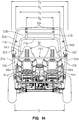
- rear passenger hand bar 290 extends between uprights 246, and as best shown in Fig. 14 , extends behind front seats 64, as described below.
- rear seat bottoms 66a are shown elevated relative to front seat bottoms 64a.
- the rear passenger hand bar 290 which extends behind front seat backs 64b is, positioned at shoulder height relative to the persons in front seats 64.
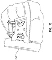
- seat belt retractor 300 is positioned on hand bar 290, and is attached to bracket 302 which is connected between hand bar 290 and upright 246. This places the seat belt retractor 300 in a convenient location for those in front seats 64, yet keeps the retractor away from the rear passengers.
- Vehicle 10 is also ergonomically designed for the rear passenger's riding experience.
- uprights 246 are shown flaring outwardly.
- uprights at the frame are spaced apart by a dimension of D 1 but extend upwardly to a dimension of D 2 which is larger than D 1 . This provides a spacing at 310 between uprights and seat backs 64b providing extra room for the passenger's knees.
- the vehicle design also provides easy ingress and egress. As shown best in Fig. 14 , the driver and front passenger may easily enter vehicle 10 without contacting longitudinally extending sections 238. This is due to the fact that the distance (D 6 ) between sections 238 is less than the extreme position adjacent the top of uprights 234 (D 5 ) and is less than the distance between the extreme position adjacent the top of uprights 246 (D 4 ). This insetting of longitudinally extending sections 238 provides easy ingress. In a like manner relating to the rear passengers, and as best shown in Figs. 4 , 6 and 14 , longitudinally extending section 264 are inset from extreme positions of both uprights 246 and 260, that is D 6 is less than both D 2 and D 7 ( Figs. 4 and 6 ). This provides easy ingress for rear passengers.
- the design also provides an enhanced ride for the rear passenger. Due to the elevated rear seats 66, the rear passengers can view over the top of the front seats 64. As shown best in Fig. 7 , the elevation of the seats is such that the hip pivot axis (H-point) of the rear passenger (H 2 ) is higher than the H-point of the driver (H 1 ). Also, for ride purposes, the H-point of the rear passenger (H 2 ) is positioned either over, or forward of, the centerline of the rear axle. As shown best in Fig. 7 , H 2 and the axle centerline are spaced apart by a distance D 8 .
- a seating position 310 of the rear passenger is positioned lower than a top 320 of the engine 322.
- the seating position is the location on the seat having the highest distribution of load from the passenger while idle. This area is normally substantially adjacent to an intersecting line through the torso of the passenger and the seat bottom 66a. In the illustrated embodiment of Fig. 7 , this distance is shown as D 9 .
- seating position 310 is also forward of, a forward most point 330 of engine 322, and as shown best in Fig. 7 , this distance is depicted as D 10 . It should be appreciated that the seating positions could also be lower than the highest point 320 of engine 322 and behind the forward most point 330, if the seats laterally straddled the engine 322.
- each seat 64, 66 may be removed.
- the seat 64 is shown having a lower base 350 having locking feet 352 receivable under latch hook 122 and a latch 354 which is receivable over latching pin 126.
- Latch release 356 releases latch 354 from the latch-locked condition. This provides access to a battery (not shown) in battery box 360.
- transverse tube 124 is bolted to stand-offs 254 ( Fig. 9 ), removal of tube 124 allows the molded covering 360 to be easily removed.
- one or more of the rear seats 66 may be removed in an identical manner to that described with respect to front seats 64. Removing one or more of the rear seats may be desired if extra storage space is required and the space is not required for a rider.
- accessory mounts could be provided (having a similar construction and footprint to that of seat base 350) and snapped in place in one or both seat positions.
- such accessories could include coolers, tool boxes, trunks, water tanks, fuel containers, camping/fishing gear, a dog crate/kennel, and the like. This enhances the functionality of vehicle 10.
- Vehicle 410 includes a frame 412, with ground engaging members 414 and 416 in the form of tires, which are driven by a drive train 430.
- a body 440 surrounds the frame and forms the outer shell of the vehicle.
- a front seating area 460 and a rear seating area 462 are formed and would include seats similar to that described above as 64 and 66.
- Vehicle 410 also includes a roll cage 470 which defines a canopy around first and second seating areas 460, 462.
- Roll cage 470 includes a front section 472, a center section 474 and a rear section 476.
- Roll cage 470 includes a front frame upright 534, a center frame upright 546 and a rear frame upright 560.
- a driver's ingress/egress 570 is defined between the center upright 546 and a front left fender 572.
- a left rear ingress/egress 574 is defined between center upright 546 and rear upright 570.
- Right side ingress/egress would also be provided in mirror image to the left hand side of the vehicle.
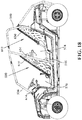
- a front side net assembly 600 is shown in the latched position and substantially encloses the driver's ingress/egress 570.
- a left rear side net assembly 602 is shown which substantially encloses the left rear ingress/egress 574.
- front side net assembly 600 is comprised of a pivotal bar 610 having an end which attaches to a pivot link 612 on the center upright 546 and an opposite end which is attached to a latching tongue 614 attached to front upright 534.
- Side net assembly 600 further comprises netting 620 fixed to the pivotal bar 610 as further described herein.
- rear side net assembly 602 is comprised of a pivotal bar 630 attached to a pivot link 632 attached to the rear upright 560 and to a latching tongue 634 attached to the rear side of center upright 546.
- pivot bar 610 includes a first end 640 and a second and opposite end 642.
- first end 640 includes an aperture 646 for pivotally mounting pivotal bar 16
- second end 642 includes a latch assembly 648 which is substantially similar to a seatbelt buckle having a slot 650 for receipt of tongue 614 ( Fig. 17 ).
- Pivotal bar 610 further includes an end cap 652 comprised of cap parts 654 and 656 which are coupled together to surround latch assembly 648.
- Pivotal bar 610 further includes elongate halves 660 and 662 which define clamp parts which couple together in a clamshell-style to encompass the netting as described herein. As shown best in Fig. 20 , clamp parts 660 and 662 define a slot 664 to receive the netting therethrough.
- Elongate halves 660, 662 of pivotal bar 610 each include ribs 668, having interruptions at 670 as described herein.
- An aperture 672 is located opposite to aperture 646.
- a first clasp 680 is provided at the rearwardmost end of the net 620 ( Fig. 24 ) and as shown best in Fig. 25 , includes an aperture 682 and a slot at 684.
- a second clasp 690 is provided at the forwardmost end of the net 620 ( Fig. 24 ) and as best shown in Fig. 26 includes an aperture 692, slot 694, apertures 696, and slots 698, 700.
- buckle 648 includes a mounting post 710 having an aperture 712. Buckle 648 also includes a release button 714. Fasteners in the form of a bolt 716, and nut 718 are also provided, as described herein. Furthermore, each of the end caps 654, 656 includes standoffs 720 which include apertures therethrough for receipt of other fasteners, as described herein.
- netting 620 includes an upper marginal edge 730 having a plurality of openings 732 therethrough which are reinforced by eyelets 734.
- Netting 620 also includes vertical strap portions 740 and horizontal strap portions 742 which define openings 746 of the netting. It should be appreciated that any material could be used for the netting such as nylon strapping or it could be a one-piece molded pliable plastic material.
- upper marginal edge 730 of the netting is sewn into slots 684 and 694 of the respective clasps 680, 690.
- Post 710 ( Fig. 24 ) is placed in position adjacent to aperture 692 of clasp 690 ( Fig. 26 ) and bolt 716 may be positioned through apertures 672 of halves 660, 662, passing through aperture 712 of buckle post 710 and through aperture 692 ( Fig. 26 ) of clasp 690.
- Nut 718 may then be placed on the opposite side of elongate half 660 and joined with bolt 716. It should be appreciated that interruptions 670 provide recesses for the receipt of eyelets 734 and aperture 682 ( Fig. 25 ) is positioned adjacent to apertures 646 of elongate halves 660, 662.
- Fasteners may then be positioned through apertures 750 (see Fig. 27 ) which pass through apertures 732 of eyelets 734 (see Fig. 24 ) which retain net 620 to the pivotal bar 610.
- Fasteners are now positioned through apertures 752 ( Fig. 27 ) which extend through standoffs 720 ( Fig. 24 ) and which also pass through apertures 696 ( Fig. 26 ) between the two end cap halves 654, 656.
- end cap 648 encompasses fasteners 716, 718, and also positions buckle 648 in its proper upright position.
- side netting 600 can now be attached to central upright 646 by positioning a fastener through aperture 646 ( Fig. 27 ) and through pivot member 612.
- the lower end of the netting would also include eyelets which are fastened to the vehicle floorboard.
- side netting 600 substantially encloses the driver ingress/egress 570 when the buckle 640 is latched to the associated latching tongue 614.
- the release button 714 is actuated, the buckle 648 is released from the latching tongue 614 which allows the pivotal bar 610 to rotate counterclockwise to the position shown in Fig. 18 , where the pivotal bar 610 and the net 620 are in a collapsed position.
- the pivotal bar 610 is bowed outwardly which provides increased interior room for the driver.
- pivotal bar 610 on the front passenger side would also be bowed outwardly, or would be a mirror image of the pivotal bar 610 as described and as displayed in Figs. 19 and 20 .
- pivotal bar 602 could be assembled in an identical manner as just described to cover the ingress/egress 574 for the rear passengers.
- FIG. 28-33 another example of a utility vehicle is shown at 810.
- the vehicle is substantially similar to that as described in Figs. 1-16 or 17-27.
- the vehicle 810 includes a frame 812, and although not specifically shown, would include ground engaging members in the form of tires, which are driven by a drive train.
- a body 840 surrounds the frame and forms the outer shell of the vehicle.
- a front seating area 860 is formed and would include seats similar to that described above as 64 and 66.
- Vehicle 810 could be a 2 passenger or a 4 passenger vehicle, but as shown is a 2 passenger vehicle.
- Vehicle 810 also includes a roll cage 870 which defines a canopy around front seating area 860.
- Roll cage 870 includes a front section 872 and a rear section 876.
- the vehicle would include a driver's ingress/egress and a passenger's ingress/egress. The passenger's ingress/egress is shown at 874 between front section 872 and rear section 876.
- a side net assembly 900 is shown in the latched position and substantially encloses the passenger's ingress/egress 874.
- side net assembly 900 is comprised of a pivotal bar 910 ( Fig. 28A ) having an end which attaches to a pivot link 912 on the floorboard 922 and an opposite end which is positioned within a marginal edge 936 of netting 920.
- a latching tongue 914 attaches to front section 872.
- Latching tongue 914 is tethered to front section 872 by a strap or clamp, and a clip 916 ( Figs. 28 and 29 ) is clipped to the front section 872.
- the clip 916 has arms which surround and rigidify the latching tongue 914, in order to make the latching process a one handed operation.
- pivotal bar 910 includes rod 920 having a first end 940 and a second and opposite end (not shown). As shown best in Figs. 28A and 30 , first end 940 includes an enlarged end 946 for pivotally mounting pivotal bar 910 whereas second end is positioned and fixed within the marginal edge 936 of netting 920.
- Pivot link 912 includes a trapezoidally shaped body 960 having an upper wall 962, lower wall 964, side walls 966 and 968, and rear wall 970.
- Upper wall 962 includes a semi-circular opening 972 (opening rearwardly) and lower wall 964 includes a semi-circular opening 974(opening forwardly).
- Rear wall 970 includes a slot 976 which feeds into semi-circular opening 974.
- Semi-circular opening 974 is larger than a diameter of rod 920 but smaller than a diameter of enlarged end 946.
- Slot 976 is larger than a profile of enlarged end 946.
- netting 920 includes an upper marginal edge 930, lower marginal edge 932, rear marginal edge 934 and front marginal edge 936.
- Netting 920 also includes strap portions 940. It should be appreciated that any material could be used for the netting such as nylon strapping or it could be a one-piece molded pliable plastic material.
- net assembly 900 would include buckle 948 attached to an end of marginal edge 936 of net 900.
- Buckle 948 includes a release button (not shown) substantially the same as that shown in Fig. 24 .
- Side net 920 is also hinged about the rear section 876 at pointes 950, 952, 954 and 956. This allows the side nets 020 to swing open when latch 948 is released.
- side net assembly 900 substantially encloses the driver ingress/egress 874 when the buckle 948 is latched to the associated latching tongue 914.
- the release button is actuated, the buckle 948 is released from the latching tongue 914 which allows the net 900 to rotate to the position shown in Fig. 29 , where the pivotal bar 910 and the net 920 are in a collapsed position. This opens up the driver's ingress/egress 874 allowing the driver to enter or exit from the vehicle.
- pivot bar 910 is positioned with enlarged end 946 towards pivot link 912, such that the enlarged end 946 is positioned through slot 976 ( Fig. 30 ).
- Pivot bar 910 is then rotated as shown in Fig. 32 which positions enlarged end 946 below opening 974, and rod portion 920 in opening 974.
- the buckle 948 is then latched with latch 914 to create the latched condition of Fig. 28 .
Landscapes
- Engineering & Computer Science (AREA)
- Transportation (AREA)
- Mechanical Engineering (AREA)
- Chemical & Material Sciences (AREA)
- Combustion & Propulsion (AREA)
- Aviation & Aerospace Engineering (AREA)
- Body Structure For Vehicles (AREA)
- Automatic Cycles, And Cycles In General (AREA)
- Vehicle Step Arrangements And Article Storage (AREA)
- Superconductors And Manufacturing Methods Therefor (AREA)
- Transition And Organic Metals Composition Catalysts For Addition Polymerization (AREA)
Description
- The present invention relates to side-by-side all terrain vehicles having netting enclosing the seating area.
- Generally, all terrain vehicles ("ATVs") and utility vehicles ("UVs") are used to carry one or two passengers and a small amount of cargo over a variety of terrains. Due to increasing recreational interest in ATVs, specialty ATVs, such as those used for trail riding, racing, and cargo hauling have entered the market place. Most ATVs include seating for up to two passengers which are either seated side-by-side or with the passenger positioned behind the driver of the ATV. Side-by-side ATVs, in which the driver and passenger are seated beside each other on laterally spaced apart seats, have become popular because of the ability to allow the passenger to share the driver's viewpoint.
-
WO03042026 -
EP1602523 relates to an automobile, which allows all of its occupants, including those in the rear seats, total vision of the road and landscape both through the front and the sides of the vehicle. -
WO03055716 -
EP1600326 relates to a vehicle which includes a front portion seat and a rear portion seat disposed rearward of the front portion seat. The rear portion seat includes seating portions offset sideways relative to the front portion seat. -
WO2008013564 andUS2008023249 relate to side-by-side all-terrain vehicles having at least a pair of laterally spaced apart seating surfaces and in particular to trail compliant side-by-side all-terrain vehicles. - An utility vehicle according to the invention is defined in appended claim 1, with further embodiments defined in dependent claims. It includes a frame extending in a generally longitudinal direction, and having at least one elongate frame tube assembly comprised of plural sections and a drive train is supported by the frame. A frame tube coupler couples the frame tube sections, where the frame tube coupler comprises coupler sections associated with each coupler end, and the coupler sections having complementary interengagement elements. Fasteners retain the interengaging elements together, where the fasteners are in tension to force the complementary interengaging elements into engagement. In this manner, any shear force is substantially taken up by the complementary interengaging elements.
- The above mentioned and other features of this invention, and the manner of attaining them, will become more apparent and the invention itself will be better understood by reference to the following description of embodiments of the invention as well as illustrative examples outside the scope of the invention taken in conjunction with the accompanying drawings, where:
-
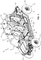
Fig. 1 shows a left front perspective view of a vehicle according to the invention; -
Fig. 2 shows a left rear perspective view of the vehicle ofFig. 1 ; -
Fig. 3 shows a left side view of the vehicle ofFig. 1 ; -
Fig. 4 shows a top view of the vehicle ofFig. 1 ; -
Fig. 5 shows a front view of the vehicle ofFig. 1 ; -
Fig. 6 shows a rear view of the vehicle ofFig. 1 ; -
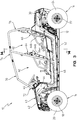
Fig. 7 shows a left side view of the vehicle similar to that ofFig. 3 showing the chassis removed and the tubular frame exposed, in which couplers couple frame tubes together according to the invention; -
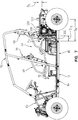
Fig. 8 shows the right side view of the vehicle ofFig. 7 ; -
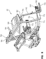
Fig. 9 is a front perspective view of the vehicle frame and roll cage; -
Fig. 10 shows an enlarged view of the vehicle main frame showing the locations of frame couplers according to the invention; -
Fig. 11 shows an enlarged view of the vehicle front frame showing the locations of frame couplers according to the invention; -
Fig. 12 is a partially exploded and fragmented perspective view showing the coupler for coupling the main frame and front frame together according to the invention.
The following figures and description sections associated therewith are illustrative of further aspects of the disclosed vehicle that do not form part of, the invention. -
Fig. 13 shows a top perspective view of the roll cage; -
Fig. 14 shows a cross-sectional view through lines 12-12 ofFig. 3 ; -
Fig. 15 shows an enlarged view of the seat belt retractor; -
Fig. 16 shows a perspective view of the seat poised for receipt in one of the seating areas; and -
Fig. 17 shows a side view of an embodiment of the vehicle described above including collapsible side nets, with the nets in the up and latched position; -
Fig. 18 shows a side view of the embodiment of the vehicle ofFIG. 17 with the nets in the collapsed and unlatched position; -
Fig. 19 shows a top perspective view of the pivotal bar; -
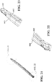
Fig. 20 shows a bottom perspective view of the pivotal bar ofFig. 19 ; -
Fig. 21 shows a bottom perspective view of the pivotal bar ofFig. 19 with the end cap removed; -
Fig. 22 shows an enlarged view of the portion denoted inFig. 21 ; -
Fig. 23 shows an enlarged view of the portion denoted inFig. 21 ; -
Fig 24 shows a plan view of the pivotal bar separated, showing the netting poised for attachment to the bar; -
Fig. 25 shows a plan view of a first clasp; -
Fig. 26 shows a plan view of a second clasp; -
Fig. 27 shows an assemble view of the pivotal bar; -
Fig. 28 is a right hand side view of an alternate side net assembly; -
Fig. 28A is an enlarged view of the portion denoted inFig. 28 ; -
Fig. 29 shows the side net assembly ofFig. 28 with the side net collapsed; -
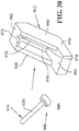
Fig. 30 shows a view of the side net post poised for receipt in the pivotal link; and -
Figs. 31-33 show a diagrammatic progressive view of the side net post and pivotal link. - Corresponding reference characters indicate corresponding parts throughout the several views. The drawings are not necessarily to scale and certain features may be exaggerated in order to better illustrate and explain the present invention as well as illustrative examples.
- The embodiments and illustrative examples disclosed below are not intended to be exhaustive or to limit the invention to the precise forms disclosed in the following detailed description. Rather, the embodiments and illustrative examples are chosen and described so that others skilled in the art may utilize their teachings. For example, while the following description refers primarily to UVs, certain features described herein may be applied to other applications such as ATVs, snowmobiles, motorcycles, mopeds, etc.
- With reference first to
Figs. 1-6 , the vehicle of the present disclosure will be described. The vehicle is shown generally at 10 and is commonly referred to as an all terrain vehicle (ATV), a side-by-side vehicle (SxS) or a utility vehicle. As shown,vehicle 10 generally comprises a frame 12 (Fig. 2 ) supported by groundengaging members members wheels 18 andtires 20; andwheels 22 andtires 24.Vehicle 10 further comprises a drive train 30 (Fig. 2 ) operatively connected toframe 12 and drivingly connected to one or more of theground engaging members drive train 30 is comprised of a fuel-burning engine and transmission combination, together with a driveshaft extending between the drive train and the frontground engaging members 14. However, any drive train could be contemplated such as hybrid, fuel cell or electric. - As shown in
Figs. 1 and2 ,vehicle 10 further includes a body portion or chassis shown generally at 40 to include ahood 42,front fender 44,dash 46,sideboard 48,front floorboard 50,rear sideboard 52,rear floorboard 54 andrear cargo area 56. As also shown,vehicle 10 is comprised of two seating areas, namely afront seating area 60 and arear seating area 62 wherefront seating area 60 is comprised of side-by-side seats, shown asbucket seats 64; andrear seating area 62 is comprised of side-by-side seats, shown asbucket seats 66. As shown best inFig. 3 , front seats include aseat bottom 64a and a seat back 64b, whilerear seat 66 includes aseat bottom 66a and a seat back 66b.Vehicle 10 also includes aroll cage 70 comprised of afront section 72, acenter section 74, and arear section 76, where the front 72,center 74 and rear 76 sections are comprised of a plurality of frame tubes attached to each other and to frame 12 as more fully described herein. - With respect now to
Figs. 7-12 ,frame 12 will be described in greater detail.Frame 12 is generally comprised of amain frame section 80 and afront frame section 82, where the two sections are interconnected by way ofcouplers 84 according to the invention. With reference first toFigs. 9 and10 , themain frame section 80 is generally comprised of two longitudinal frame rails 90 interconnected by a plurality of struts such as 92, 94, 96 attaching frame rails 90 together in a predefined spaced-apart relation.Main frame section 80 also comprises a drivetrain mounting section 102 extending at a rear portion ofmain frame 80. - With respect now to
Fig. 10 ,frame 80 also defines frontseat support platform 110 and rearseat support platform 112. Frontseat support platform 110 includes a transversely extendingtube 114 havinglegs 116 attached toouter frame rail 118 andinner legs 120 directly attached to frametubes 90.Frame tube 114 spans the distance across frame rails 118 and theframe tubes 90. With reference still toFig. 10 ,frame tubes 114 include alatch hook 122 as described further herein. Frontseat support platform 110 further includes atransverse frame member 124 which as best shown inFig. 9 is attached to rollcage center section 74 as further described herein.Frame tube 124 includes latchingpins 126 for inter-engagement withseats 64. - With reference still to
Fig. 10 , rearseat support platform 112 is comprised offrame tubes 130 which provide an elevated platform fortransverse frame tubes Frame tubes 132 have latch hooks 136 (similar in nature to latch hooks 122) andframe tube 134 has latching pins 138 (similar to latching pins 126). - With respect still to
Fig. 10 ,main frame member 80 further includes rollcage mounting sections section 150 includes aplate 154 on eachside spanning tube 90 andframe rail 118. Mountingsection 152 is provided by aplate 156 provided onframe tube 158 which spansuprights 160 offrame rail 118. - With respect now to
Fig. 11 ,front frame member 82 will be described in greater detail.Front frame member 82 includesframe tubes 170 which complementframe tubes 90, and are held in a fixed relation bytubes tubes 170 by way of astrut 180.Front frame 82 further comprises front rollcage mounting sections 182 comprisingplates 184 positioned betweencross tubes uprights - As described,
frame 80 is comprised ofmain frame member 90 andfront frame member 82. Splitting the frame into two separate modular subassemblies allows for easier processing of theentire vehicle 10. Due to the load on theframe tubes coupler 84 takes place at a longitudinal position from either end of theframe 80, within a distance from the end, of approximately 30% of the length offrame 80. Thecoupler 84 could also be placed at the rear offrame tubes 90. - With reference now to
Fig. 12 ,frame tube coupler 84 according to the invention is shown poised for receipt withinframe tubes coupler 84 is comprised ofindividual coupler members 200. Thecoupler members 200 are identical, and each comprises atube connecting section 202 and an alignment orinterengaging section 204. Theinterengaging sections 204 include interengaging elements, shown here asprojections 206 and recesses 208.Projections 206 are shown as frusto-conical in shape, and recesses have a complementary frusto-conical recessed configuration. Theinterengaging sections 204 further compriseapertures 216 which self align withapertures 216 in theopposite interengaging section 204 whencomplementary projections 206 and recesses 208 align. As also shown inFig. 12 ,tube connecting sections 202 includelegs 210 and stand-offs 212. Finally, a connectingbracket 220 is provided for connectingframe rails - To connect
main frame member 80 andfront frame member 82, theindividual coupler members 200 are each inserted into respective ends of theframe tubes offs 212 abut an end edge of theframe tubes individual couplers 200 to theframe tubes individual couplers 200 are shown welded in place torespective frame tubes Figs. 10 and11 . -
Coupler 84 allows alignment offrame tubes individual couplers 200 are each aligned withrespective frame tubes individual couplers 200 are alignable to each other.Couplers 84 also allow alignment offrame tubes main frame 80 andfront frame 82 are not themselves perfectly aligned. That is, once individual coupler members are close to alignment, fasteners (not shown) are positioned into and throughcomplementary apertures 216, whereby the fasteners may be drawn tight until the projections and recesses are in engagement with each other. This aligns thetubes coupler 84 is taken up through the projections and recesses, not through the fasteners. - What follows is a description of further illustrative aspects of the disclosed vehicle that do not form part of the invention.
- With respect now to
Fig. 13 ,roll cage 70 is shown comprised offront 72,center 74 and rear 76 roll cage sections. Each of athe cage sections comprise plural frame tubes as shown. The cage sections are shown connected atconnection joints - Front
roll cage section 72 is comprised ofuprights 234,transverse sections 236, and longitudinally extendingsections 238.Mounts 240 are provided at the front and extend fromuprights 234. It should be appreciated that mounts 240 cooperate with mounting sections 182 (Fig. 11 ) by way of fasteners (not shown). - Center
roll cage section 74 is comprised ofuprights 246,transverse section 248 and longitudinally extendingsections 250.Mounts 252 are provided at the lower end ofupright 246 and is comprised of stand-offs 254 and mountingbrackets 256. It should be appreciated that mountingbrackets 256 cooperate with mounting section 150 (Fig. 10 ) by way of fasteners (not shown). - Rear
roll cage section 76 is comprised ofuprights 260, transverse section 262, and longitudinally extendingsection 264.Mounts 268 are provided at the lower end ofuprights 260 which cooperate with mounting sections 152 (Fig. 10 ). -
Roll cage assembly 70 comprises ergonomic features for the driver and passengers. First, supports 276 are provided onuprights 246 extending forwardly. These supports are positioned adjacent toseats 64, as shown inFigs. 1 and2 , and enclose the driver and front passenger. Second, supports 280 are provided betweenuprights upper portion 282,lower portion 284 andtransition portion 286. As shown inFig. 1 ,support 280 is shown in position where lower portion extends across the entry spaced abovefloorboard 54.Transition section 286 andupper portion 282 extend across theseat 66 and enclose the rear passengers. Finally, rearpassenger hand bar 290 extends betweenuprights 246, and as best shown inFig. 14 , extends behindfront seats 64, as described below. - As shown in
Fig. 14 ,rear seat bottoms 66a are shown elevated relative tofront seat bottoms 64a. Thus the rearpassenger hand bar 290, which extends behind front seat backs 64b is, positioned at shoulder height relative to the persons in front seats 64. As shown best inFig. 15 ,seat belt retractor 300 is positioned onhand bar 290, and is attached tobracket 302 which is connected betweenhand bar 290 andupright 246. This places theseat belt retractor 300 in a convenient location for those infront seats 64, yet keeps the retractor away from the rear passengers. -
Vehicle 10 is also ergonomically designed for the rear passenger's riding experience. For example, and with respect still tofig. 14 ,uprights 246 are shown flaring outwardly. For example, uprights at the frame are spaced apart by a dimension of D1 but extend upwardly to a dimension of D2 which is larger than D1. This provides a spacing at 310 between uprights and seat backs 64b providing extra room for the passenger's knees. - The vehicle design also provides easy ingress and egress. As shown best in
Fig. 14 , the driver and front passenger may easily entervehicle 10 without contacting longitudinally extendingsections 238. This is due to the fact that the distance (D6) betweensections 238 is less than the extreme position adjacent the top of uprights 234 (D5) and is less than the distance between the extreme position adjacent the top of uprights 246 (D4). This insetting of longitudinally extendingsections 238 provides easy ingress. In a like manner relating to the rear passengers, and as best shown inFigs. 4 ,6 and14 , longitudinally extendingsection 264 are inset from extreme positions of bothuprights Figs. 4 and6 ). This provides easy ingress for rear passengers. - The design also provides an enhanced ride for the rear passenger. Due to the elevated
rear seats 66, the rear passengers can view over the top of thefront seats 64. As shown best inFig. 7 , the elevation of the seats is such that the hip pivot axis (H-point) of the rear passenger (H2) is higher than the H-point of the driver (H1). Also, for ride purposes, the H-point of the rear passenger (H2) is positioned either over, or forward of, the centerline of the rear axle. As shown best inFig. 7 , H2 and the axle centerline are spaced apart by a distance D8. Also, in order to enhance the ride of the rear passenger, as well as keep the center of gravity low, aseating position 310 of the rear passenger is positioned lower than a top 320 of theengine 322. The seating position is the location on the seat having the highest distribution of load from the passenger while idle. This area is normally substantially adjacent to an intersecting line through the torso of the passenger and theseat bottom 66a. In the illustrated embodiment ofFig. 7 , this distance is shown as D9. Finally,seating position 310 is also forward of, a forwardmost point 330 ofengine 322, and as shown best inFig. 7 , this distance is depicted as D10. It should be appreciated that the seating positions could also be lower than thehighest point 320 ofengine 322 and behind the forwardmost point 330, if the seats laterally straddled theengine 322. - With respect now to
Fig. 16 , thevehicle 10 provides enhanced serviceability and functionality. As shown, eachseat seat 64 is shown having alower base 350 having lockingfeet 352 receivable underlatch hook 122 and alatch 354 which is receivable over latchingpin 126.Latch release 356 releases latch 354 from the latch-locked condition. This provides access to a battery (not shown) inbattery box 360. Also astransverse tube 124 is bolted to stand-offs 254 (Fig. 9 ), removal oftube 124 allows the molded covering 360 to be easily removed. - It should be appreciated that one or more of the
rear seats 66 may be removed in an identical manner to that described with respect tofront seats 64. Removing one or more of the rear seats may be desired if extra storage space is required and the space is not required for a rider. Also, accessory mounts could be provided (having a similar construction and footprint to that of seat base 350) and snapped in place in one or both seat positions. For example, such accessories could include coolers, tool boxes, trunks, water tanks, fuel containers, camping/fishing gear, a dog crate/kennel, and the like. This enhances the functionality ofvehicle 10. - With respect now to
Fig. 17 , another example of a utility vehicle is shown at 410. The vehicle is substantially similar to that as described inFigs. 1-16 .Vehicle 410 includes aframe 412, withground engaging members drive train 430. Abody 440 surrounds the frame and forms the outer shell of the vehicle. Afront seating area 460 and arear seating area 462 are formed and would include seats similar to that described above as 64 and 66. -
Vehicle 410 also includes aroll cage 470 which defines a canopy around first andsecond seating areas Roll cage 470 includes afront section 472, acenter section 474 and arear section 476.Roll cage 470 includes afront frame upright 534, acenter frame upright 546 and arear frame upright 560. As shown, a driver's ingress/egress 570 is defined between thecenter upright 546 and a frontleft fender 572. Similarly a left rear ingress/egress 574 is defined between center upright 546 andrear upright 570. Right side ingress/egress would also be provided in mirror image to the left hand side of the vehicle. - In this example, and with reference to
Fig. 17 , a front sidenet assembly 600 is shown in the latched position and substantially encloses the driver's ingress/egress 570. In a similar manner, a left rear sidenet assembly 602 is shown which substantially encloses the left rear ingress/egress 574. - As shown, front side
net assembly 600 is comprised of apivotal bar 610 having an end which attaches to apivot link 612 on thecenter upright 546 and an opposite end which is attached to a latchingtongue 614 attached tofront upright 534. Sidenet assembly 600 further comprises netting 620 fixed to thepivotal bar 610 as further described herein. - In a similar manner, rear side
net assembly 602 is comprised of apivotal bar 630 attached to apivot link 632 attached to therear upright 560 and to a latchingtongue 634 attached to the rear side ofcenter upright 546. - With reference now to
Figs. 19-23 ,pivotal bar 610 will be described in greater detail. As shown,pivot bar 610 includes afirst end 640 and a second andopposite end 642. As shown best inFig. 19 ,first end 640 includes anaperture 646 for pivotally mountingpivotal bar 16 whereassecond end 642 includes alatch assembly 648 which is substantially similar to a seatbelt buckle having aslot 650 for receipt of tongue 614 (Fig. 17 ).Pivotal bar 610 further includes anend cap 652 comprised ofcap parts latch assembly 648.Pivotal bar 610 further includeselongate halves Fig. 20 , clampparts slot 664 to receive the netting therethrough. - With reference to
Figs 21-24 ,pivotal bar 610 will be described in greater detail.Elongate halves pivotal bar 610 each includeribs 668, having interruptions at 670 as described herein. Anaperture 672 is located opposite toaperture 646. Afirst clasp 680 is provided at the rearwardmost end of the net 620 (Fig. 24 ) and as shown best inFig. 25 , includes anaperture 682 and a slot at 684. Asecond clasp 690 is provided at the forwardmost end of the net 620 (Fig. 24 ) and as best shown inFig. 26 includes anaperture 692,slot 694,apertures 696, andslots - As also best shown in
Fig. 24 ,buckle 648 includes a mountingpost 710 having anaperture 712.Buckle 648 also includes arelease button 714. Fasteners in the form of abolt 716, andnut 718 are also provided, as described herein. Furthermore, each of the end caps 654, 656 includesstandoffs 720 which include apertures therethrough for receipt of other fasteners, as described herein. - With reference still to
Fig. 24 , netting 620 includes an uppermarginal edge 730 having a plurality ofopenings 732 therethrough which are reinforced byeyelets 734. Netting 620 also includesvertical strap portions 740 andhorizontal strap portions 742 which defineopenings 746 of the netting. It should be appreciated that any material could be used for the netting such as nylon strapping or it could be a one-piece molded pliable plastic material. - To assemble the netting 600, upper
marginal edge 730 of the netting is sewn intoslots respective clasps Fig. 24 ) is placed in position adjacent toaperture 692 of clasp 690 (Fig. 26 ) andbolt 716 may be positioned throughapertures 672 ofhalves aperture 712 ofbuckle post 710 and through aperture 692 (Fig. 26 ) ofclasp 690.Nut 718 may then be placed on the opposite side ofelongate half 660 and joined withbolt 716. It should be appreciated thatinterruptions 670 provide recesses for the receipt ofeyelets 734 and aperture 682 (Fig. 25 ) is positioned adjacent toapertures 646 ofelongate halves - Fasteners may then be positioned through apertures 750 (see
Fig. 27 ) which pass throughapertures 732 of eyelets 734 (seeFig. 24 ) which retain net 620 to thepivotal bar 610. Fasteners are now positioned through apertures 752 (Fig. 27 ) which extend through standoffs 720 (Fig. 24 ) and which also pass through apertures 696 (Fig. 26 ) between the two end cap halves 654, 656. When in position,end cap 648 encompassesfasteners buckle 648 in its proper upright position. As assembled, side netting 600 can now be attached tocentral upright 646 by positioning a fastener through aperture 646 (Fig. 27 ) and throughpivot member 612. The lower end of the netting would also include eyelets which are fastened to the vehicle floorboard. - With reference again to
Fig. 17 , side netting 600 substantially encloses the driver ingress/egress 570 when thebuckle 640 is latched to the associated latchingtongue 614. When therelease button 714 is actuated, thebuckle 648 is released from the latchingtongue 614 which allows thepivotal bar 610 to rotate counterclockwise to the position shown inFig. 18 , where thepivotal bar 610 and the net 620 are in a collapsed position. This opens up the driver's ingress/egress 570 allowing the driver to enter or exit from the vehicle. It should be appreciated that, and as best viewed inFigs. 19 and20 , thepivotal bar 610 is bowed outwardly which provides increased interior room for the driver. It should also be appreciated that apivotal bar 610 on the front passenger side, would also be bowed outwardly, or would be a mirror image of thepivotal bar 610 as described and as displayed inFigs. 19 and20 . Finally, it should also be appreciated thatpivotal bar 602 could be assembled in an identical manner as just described to cover the ingress/egress 574 for the rear passengers. - With respect now to
Figs. 28-33 , another example of a utility vehicle is shown at 810. The vehicle is substantially similar to that as described inFigs. 1-16 or 17-27. Thevehicle 810 includes aframe 812, and although not specifically shown, would include ground engaging members in the form of tires, which are driven by a drive train. Abody 840 surrounds the frame and forms the outer shell of the vehicle. Afront seating area 860 is formed and would include seats similar to that described above as 64 and 66.Vehicle 810 could be a 2 passenger or a 4 passenger vehicle, but as shown is a 2 passenger vehicle. -
Vehicle 810 also includes aroll cage 870 which defines a canopy aroundfront seating area 860.Roll cage 870 includes afront section 872 and arear section 876. Furthermore, the vehicle would include a driver's ingress/egress and a passenger's ingress/egress. The passenger's ingress/egress is shown at 874 betweenfront section 872 andrear section 876. - In this example, and with reference to
Fig. 28 , a side net assembly 900 is shown in the latched position and substantially encloses the passenger's ingress/egress 874. As shown, side net assembly 900 is comprised of a pivotal bar 910 (Fig. 28A ) having an end which attaches to apivot link 912 on thefloorboard 922 and an opposite end which is positioned within amarginal edge 936 of netting 920. A latchingtongue 914 attaches tofront section 872. Latchingtongue 914 is tethered tofront section 872 by a strap or clamp, and a clip 916 (Figs. 28 and29 ) is clipped to thefront section 872. Theclip 916 has arms which surround and rigidify the latchingtongue 914, in order to make the latching process a one handed operation. - With reference now to
Figs. 28A and30 ,pivotal bar 910 will be described in greater detail. As shown,pivotal bar 910 includesrod 920 having afirst end 940 and a second and opposite end (not shown). As shown best inFigs. 28A and30 ,first end 940 includes anenlarged end 946 for pivotally mountingpivotal bar 910 whereas second end is positioned and fixed within themarginal edge 936 of netting 920. - With reference to
Fig. 30 ,pivot link 912 will be described in greater detail.Pivot link 912 includes a trapezoidally shapedbody 960 having anupper wall 962,lower wall 964,side walls rear wall 970.Upper wall 962 includes a semi-circular opening 972 (opening rearwardly) andlower wall 964 includes a semi-circular opening 974(opening forwardly).Rear wall 970 includes aslot 976 which feeds intosemi-circular opening 974.Semi-circular opening 974 is larger than a diameter ofrod 920 but smaller than a diameter ofenlarged end 946.Slot 976 is larger than a profile ofenlarged end 946. - With reference again to
Fig. 28 , netting 920 includes an uppermarginal edge 930, lowermarginal edge 932, rearmarginal edge 934 and frontmarginal edge 936. Netting 920 also includesstrap portions 940. It should be appreciated that any material could be used for the netting such as nylon strapping or it could be a one-piece molded pliable plastic material. - As also best shown in
Figs. 28 and29 , net assembly 900 would includebuckle 948 attached to an end ofmarginal edge 936 of net 900.Buckle 948 includes a release button (not shown) substantially the same as that shown inFig. 24 .Side net 920 is also hinged about therear section 876 at pointes 950, 952, 954 and 956. This allows the side nets 020 to swing open whenlatch 948 is released. - With reference still to
Fig. 28 , side net assembly 900 substantially encloses the driver ingress/egress 874 when thebuckle 948 is latched to the associated latchingtongue 914. When the release button is actuated, thebuckle 948 is released from the latchingtongue 914 which allows the net 900 to rotate to the position shown inFig. 29 , where thepivotal bar 910 and the net 920 are in a collapsed position. This opens up the driver's ingress/egress 874 allowing the driver to enter or exit from the vehicle. - To latch the net assembly 900, and with reference to
Figs. 30 - 33 , thepivot bar 910 is positioned withenlarged end 946 towardspivot link 912, such that theenlarged end 946 is positioned through slot 976 (Fig. 30 ).Pivot bar 910 is then rotated as shown inFig. 32 which positionsenlarged end 946 below opening 974, androd portion 920 inopening 974. Continued rotation ofpivot bar 910 to the position ofFig. 33 causes thepivot bar 910 to also be positioned inopening 972. Thebuckle 948 is then latched withlatch 914 to create the latched condition ofFig. 28 .
Claims (6)
- A utility vehicle (10), comprising a frame (12) extending in a generally longitudinal direction and a drive train (30) supported by the frame, the frame having at least one elongate frame tube assembly (80) comprised of plural tube sections (90, 170) and a frame tube coupler (84) adapted for coupling the frame tube sections (90, 170) of tube assembly (80), the frame tube coupler (84) comprising a first coupler member (200) coupled to a first frame tube section (90) and a second coupler member (200) coupled to a second frame tube section (170), the first and second coupler members (200) having each complementary inter-engaging elements (206, 208) and fasteners for retaining the inter-engaging elements together, where the fasteners are in tension to force the complementary inter-engaging elements (206, 208) into engagement; wherein upon such engagement any shear force on the frame tube coupler (84) is substantially taken up by the complementary inter-engaging elements (206, 208), characterized in that each of the first and second coupler members (200) comprises a tube connecting section (202) and an inter-engaging section (204), each inter-engaging section comprises projection (206) and a recess (208) complementary in shape with the projection (206), wherein a projection of the inter-engaging section of either of the first and second coupler members (200) is profiled and positioned for receipt within the recess of the inter-engaging section of the opposite one of the first and second coupler members (200).
- The utility vehicle of claim 1, characterized in that the tube connecting section (202) of the first and second coupler members (200) is insertable into respective ends of the frame tube sections (90, 170).
- The utility vehicle of any of the preceding claims characterized in that the frame tube coupler (84) in use couples the frame tube sections (90, 170) at a longitudinal position within a distance from the front or rear end of the frame of approximately 30% of the length of the frame (12).
- The utility vehicle of claim 3, characterized in that the longitudinal position is lower than a front seating area (60) of the utility vehicle.
- The utility vehicle of claim 3, characterized in that the longitudinal position is lower than a front seating area (60) of the utility vehicle and a rear seating area (62) of the utility vehicle, both the front seating area (60) and the rear seating area (62) having side-by-side seating.
- The utility vehicle of any of claims 3 - 5 characterized in that the longitudinal position is lower than the drive train (30) of the utility vehicle.
Applications Claiming Priority (3)
| Application Number | Priority Date | Filing Date | Title |
|---|---|---|---|
| US12/484,888 US8640814B2 (en) | 2009-06-15 | 2009-06-15 | Side-by-side vehicle |
| US12/796,495 US8328235B2 (en) | 2010-06-08 | 2010-06-08 | Side-by-side vehicle |
| EP10725581A EP2443002A1 (en) | 2009-06-15 | 2010-06-15 | Side-by-side vehicle |
Related Parent Applications (1)
| Application Number | Title | Priority Date | Filing Date |
|---|---|---|---|
| EP10725581A Division EP2443002A1 (en) | 2009-06-15 | 2010-06-15 | Side-by-side vehicle |
Publications (2)
| Publication Number | Publication Date |
|---|---|
| EP2698274A1 EP2698274A1 (en) | 2014-02-19 |
| EP2698274B1 true EP2698274B1 (en) | 2017-05-03 |
Family
ID=42340747
Family Applications (2)
| Application Number | Title | Priority Date | Filing Date |
|---|---|---|---|
| EP10725581A Withdrawn EP2443002A1 (en) | 2009-06-15 | 2010-06-15 | Side-by-side vehicle |
| EP13184887.1A Not-in-force EP2698274B1 (en) | 2009-06-15 | 2010-06-15 | Side-by-side vehicle |
Family Applications Before (1)
| Application Number | Title | Priority Date | Filing Date |
|---|---|---|---|
| EP10725581A Withdrawn EP2443002A1 (en) | 2009-06-15 | 2010-06-15 | Side-by-side vehicle |
Country Status (9)
| Country | Link |
|---|---|
| EP (2) | EP2443002A1 (en) |
| CN (1) | CN102803010B (en) |
| AU (1) | AU2010260149B2 (en) |
| BR (1) | BRPI1014135A2 (en) |
| CA (4) | CA2764397C (en) |
| ES (1) | ES2626425T3 (en) |
| MX (1) | MX2011012535A (en) |
| WO (1) | WO2010148014A1 (en) |
| ZA (1) | ZA201200133B (en) |
Cited By (2)
| Publication number | Priority date | Publication date | Assignee | Title |
|---|---|---|---|---|
| US11345406B2 (en) | 2019-12-05 | 2022-05-31 | Honda Motor Co., Ltd. | Vehicle assembly with grab bar and methods of making and using the same |
| EP4056943B1 (en) | 2021-03-12 | 2025-05-21 | ACS Armoured Car Systems GmbH | Modular structure for vehicle |
Families Citing this family (24)
| Publication number | Priority date | Publication date | Assignee | Title |
|---|---|---|---|---|
| US9393894B2 (en) | 2009-06-15 | 2016-07-19 | Polaris Industries Inc. | Side-by-side vehicle |
| US9650078B2 (en) | 2011-02-11 | 2017-05-16 | Polaris Industries Inc. | Side-by-side all terrain vehicle |
| CN104044643A (en) * | 2013-03-11 | 2014-09-17 | 李晓波 | All-terrain vehicle protection frame |
| CN111483524B (en) | 2013-03-15 | 2023-05-23 | 北极星工业有限公司 | Multipurpose vehicle |
| CA3297418A1 (en) | 2013-05-31 | 2026-03-02 | Polaris Industries Inc. | Side-by-side utility vehicle |
| CN118849684A (en) | 2015-05-15 | 2024-10-29 | 北极星工业有限公司 | Multi-purpose vehicles |
| DK3663172T3 (en) | 2015-07-31 | 2021-10-18 | Polaris Inc | Commercial vehicle with folding rear cab frame |
| RU167865U1 (en) * | 2016-02-24 | 2017-01-20 | Федеральное государственное бюджетное образовательное учреждение высшего образования "Рыбинский государственный авиационный технический университет имени П.А. Соловьева" | MODULAR ATV |
| US9764768B1 (en) | 2016-02-25 | 2017-09-19 | Honda Motor Co., Ltd. | Lateral retention member |
| RU167613U9 (en) * | 2016-05-30 | 2017-03-09 | Анатолий Андреевич Лейрих | MODULAR VEHICLE |
| CN108791163B (en) * | 2017-04-29 | 2021-03-23 | 益阳天华两栖车艇有限公司 | Anti-rolling protective bar assembly |
| US10336372B1 (en) | 2018-01-22 | 2019-07-02 | Honda Motor Co., Ltd. | Vehicle frame and vehicle having same |
| US10946736B2 (en) | 2018-06-05 | 2021-03-16 | Polaris Industries Inc. | All-terrain vehicle |
| CN109318691A (en) * | 2018-09-29 | 2019-02-12 | 重庆隆鑫机车有限公司 | All-terrain vehicle canopy rod structure and all-terrain vehicle |
| LU100962B1 (en) * | 2018-10-15 | 2020-04-15 | Alpha Ec Ind 2018 S A R L | Bus structure with a vertical handle for passengers |
| CA3299418A1 (en) | 2019-04-30 | 2026-03-02 | Polaris Industries Inc. | Vehicle with removable final drive |
| CN112776890B (en) * | 2019-11-01 | 2025-07-25 | 九号智能(常州)科技有限公司 | All-terrain vehicle and vehicle body thereof |
| US12187127B2 (en) | 2020-05-15 | 2025-01-07 | Polaris Industries Inc. | Off-road vehicle |
| US11691674B2 (en) | 2020-05-15 | 2023-07-04 | Polaris Industries Inc. | Off-road vehicle |
| US11260911B2 (en) | 2020-06-30 | 2022-03-01 | Elvy Inc. | Personal electric vehicle |
| MX2023006716A (en) | 2022-06-13 | 2023-12-14 | Polaris Inc | POWER TRAIN FOR UTILITY VEHICLE. |
| USD1067123S1 (en) | 2023-01-20 | 2025-03-18 | Polaris Industries Inc. | Off-road vehicle |
| USD1120805S1 (en) | 2023-06-29 | 2026-03-31 | Polaris Industries Inc. | Body assembly for an off-road vehicle |
| US20250368287A1 (en) * | 2024-05-28 | 2025-12-04 | Huzhou Daixi Zhenhua Technology Trade Co., Ltd. | Novel four-wheeled motorcycle |
Family Cites Families (16)
| Publication number | Priority date | Publication date | Assignee | Title |
|---|---|---|---|---|
| US4344718A (en) * | 1981-11-02 | 1982-08-17 | Atlantic Richfield Company | Cold weather coupling device |
| CA1173758A (en) * | 1983-03-21 | 1984-09-04 | Pierre M. Ethier | Three-wheeled vehicle for driver and passenger seated in alignment |
| US6056078A (en) * | 1997-06-10 | 2000-05-02 | Pham; Roger N. C. | High performance fully-enclosed center-tracking vehicle |
| DE10028781B4 (en) * | 2000-06-15 | 2010-11-11 | Webasto Ag | Motor vehicle with a convertible passenger compartment |
| EP1490257A1 (en) * | 2001-11-13 | 2004-12-29 | Bombardier Recreational Products Inc. | Atv with improved driver positioning and single or multiple passenger capacity |
| ITTO20020011A1 (en) * | 2002-01-04 | 2003-07-04 | Fiat Ricerche | VEHICLE SEAT, WITH KNEE-REST ELEMENT. |
| US6652020B2 (en) * | 2002-04-09 | 2003-11-25 | Norco Industries, Inc. | Reinforcing bracket for trailer-frame butt joints |
| US20030231926A1 (en) * | 2002-06-13 | 2003-12-18 | Santana Cycles, Inc. | Tubing coupler |
| US6994388B2 (en) * | 2004-02-23 | 2006-02-07 | Kawasaki Jukogyo Kabushiki Kaisha | Pick-up style utility vehicle with adjustable cargo bed |
| ES1057838Y (en) * | 2004-05-21 | 2005-01-16 | Gonzalez Alonso Ignacio Ventur | TOTAL VISION VEHICLE FOR ALL ITS OCCUPANTS AND EXTRA LONG BOX. |
| CN100519266C (en) * | 2004-05-24 | 2009-07-29 | 本田技研工业株式会社 | Vehicle |
| JP4563840B2 (en) * | 2004-05-24 | 2010-10-13 | 本田技研工業株式会社 | vehicle |
| CN2763120Y (en) * | 2005-01-07 | 2006-03-08 | 上海延锋江森座椅有限公司 | Mechanism for turning-over or disassembling seat |
| US7819220B2 (en) * | 2006-07-28 | 2010-10-26 | Polaris Industries Inc. | Side-by-side ATV |
| US8827028B2 (en) * | 2006-07-28 | 2014-09-09 | Polaris Industries Inc. | Side-by-side ATV |
| US7488022B2 (en) * | 2007-01-08 | 2009-02-10 | Ford Global Technologies, Llc | Universal structural joint for automotive frames |
-
2010
- 2010-06-15 BR BRPI1014135A patent/BRPI1014135A2/en not_active IP Right Cessation
- 2010-06-15 CA CA2764397A patent/CA2764397C/en active Active
- 2010-06-15 MX MX2011012535A patent/MX2011012535A/en active IP Right Grant
- 2010-06-15 WO PCT/US2010/038709 patent/WO2010148014A1/en not_active Ceased
- 2010-06-15 CA CA2996361A patent/CA2996361C/en active Active
- 2010-06-15 CN CN201080026656.0A patent/CN102803010B/en active Active
- 2010-06-15 ES ES13184887.1T patent/ES2626425T3/en active Active
- 2010-06-15 EP EP10725581A patent/EP2443002A1/en not_active Withdrawn
- 2010-06-15 EP EP13184887.1A patent/EP2698274B1/en not_active Not-in-force
- 2010-06-15 AU AU2010260149A patent/AU2010260149B2/en not_active Ceased
- 2010-06-15 CA CA3106993A patent/CA3106993A1/en active Pending
- 2010-06-15 CA CA3184359A patent/CA3184359A1/en active Pending
-
2012
- 2012-01-06 ZA ZA2012/00133A patent/ZA201200133B/en unknown
Cited By (2)
| Publication number | Priority date | Publication date | Assignee | Title |
|---|---|---|---|---|
| US11345406B2 (en) | 2019-12-05 | 2022-05-31 | Honda Motor Co., Ltd. | Vehicle assembly with grab bar and methods of making and using the same |
| EP4056943B1 (en) | 2021-03-12 | 2025-05-21 | ACS Armoured Car Systems GmbH | Modular structure for vehicle |
Also Published As
| Publication number | Publication date |
|---|---|
| AU2010260149A1 (en) | 2012-02-02 |
| CA3184359A1 (en) | 2010-12-23 |
| WO2010148014A1 (en) | 2010-12-23 |
| CN102803010B (en) | 2016-06-01 |
| CN102803010A (en) | 2012-11-28 |
| CA3106993A1 (en) | 2010-12-23 |
| EP2443002A1 (en) | 2012-04-25 |
| ZA201200133B (en) | 2012-09-26 |
| AU2010260149B2 (en) | 2015-01-15 |
| CA2996361A1 (en) | 2010-12-23 |
| CA2996361C (en) | 2021-03-09 |
| CA2764397A1 (en) | 2010-12-23 |
| ES2626425T3 (en) | 2017-07-25 |
| CA2764397C (en) | 2018-04-17 |
| BRPI1014135A2 (en) | 2016-04-12 |
| EP2698274A1 (en) | 2014-02-19 |
| MX2011012535A (en) | 2011-12-16 |
Similar Documents
| Publication | Publication Date | Title |
|---|---|---|
| CA2996361C (en) | Side-by-side vehicle | |
| US8328235B2 (en) | Side-by-side vehicle | |
| US12110058B2 (en) | Side-by-side vehicle | |
| CA3019771C (en) | Side by side all terrain vehicle | |
| US11230351B2 (en) | Snowmobile fuel tank | |
| CA3030531C (en) | Seat adjustment assembly and vehicle with adjustable seats | |
| CA2801067A1 (en) | Lateral cover for a wheeled vehicle | |
| CN112776890A (en) | All-terrain vehicle and vehicle body thereof | |
| US20140210195A1 (en) | Wheeled vehicle having a seat with a lateral restraining member | |
| US4685691A (en) | Trailer for a two-wheeled vehicle | |
| HK1177180A (en) | Side-by-side vehicle |
Legal Events
| Date | Code | Title | Description |
|---|---|---|---|
| AC | Divisional application: reference to earlier application |
Ref document number: 2443002 Country of ref document: EP Kind code of ref document: P |
|
| AK | Designated contracting states |
Kind code of ref document: A1 Designated state(s): AL AT BE BG CH CY CZ DE DK EE ES FI FR GB GR HR HU IE IS IT LI LT LU LV MC MK MT NL NO PL PT RO SE SI SK SM TR |
|
| PUAI | Public reference made under article 153(3) epc to a published international application that has entered the european phase |
Free format text: ORIGINAL CODE: 0009012 |
|
| 17P | Request for examination filed |
Effective date: 20140818 |
|
| RBV | Designated contracting states (corrected) |
Designated state(s): AL AT BE BG CH CY CZ DE DK EE ES FI FR GB GR HR HU IE IS IT LI LT LU LV MC MK MT NL NO PL PT RO SE SI SK SM TR |
|
| RIC1 | Information provided on ipc code assigned before grant |
Ipc: B60N 2/01 20060101AFI20150706BHEP Ipc: B62D 31/00 20060101ALI20150706BHEP |
|
| 17Q | First examination report despatched |
Effective date: 20151002 |
|
| GRAP | Despatch of communication of intention to grant a patent |
Free format text: ORIGINAL CODE: EPIDOSNIGR1 |
|
| INTG | Intention to grant announced |
Effective date: 20161207 |
|
| GRAS | Grant fee paid |
Free format text: ORIGINAL CODE: EPIDOSNIGR3 |
|
| GRAA | (expected) grant |
Free format text: ORIGINAL CODE: 0009210 |
|
| AC | Divisional application: reference to earlier application |
Ref document number: 2443002 Country of ref document: EP Kind code of ref document: P |
|
| AK | Designated contracting states |
Kind code of ref document: B1 Designated state(s): AL AT BE BG CH CY CZ DE DK EE ES FI FR GB GR HR HU IE IS IT LI LT LU LV MC MK MT NL NO PL PT RO SE SI SK SM TR |
|
| REG | Reference to a national code |
Ref country code: GB Ref legal event code: FG4D |
|
| REG | Reference to a national code |
Ref country code: AT Ref legal event code: REF Ref document number: 889577 Country of ref document: AT Kind code of ref document: T Effective date: 20170515 Ref country code: CH Ref legal event code: EP |
|
| REG | Reference to a national code |
Ref country code: IE Ref legal event code: FG4D |
|
| REG | Reference to a national code |
Ref country code: SE Ref legal event code: TRGR |
|
| REG | Reference to a national code |
Ref country code: DE Ref legal event code: R096 Ref document number: 602010042151 Country of ref document: DE |
|
| REG | Reference to a national code |
Ref country code: FR Ref legal event code: PLFP Year of fee payment: 8 |
|
| REG | Reference to a national code |
Ref country code: ES Ref legal event code: FG2A Ref document number: 2626425 Country of ref document: ES Kind code of ref document: T3 Effective date: 20170725 |
|
| REG | Reference to a national code |
Ref country code: NL Ref legal event code: MP Effective date: 20170503 |
|
| REG | Reference to a national code |
Ref country code: AT Ref legal event code: MK05 Ref document number: 889577 Country of ref document: AT Kind code of ref document: T Effective date: 20170503 |
|
| REG | Reference to a national code |
Ref country code: LT Ref legal event code: MG4D |
|
| PG25 | Lapsed in a contracting state [announced via postgrant information from national office to epo] |
Ref country code: LT Free format text: LAPSE BECAUSE OF FAILURE TO SUBMIT A TRANSLATION OF THE DESCRIPTION OR TO PAY THE FEE WITHIN THE PRESCRIBED TIME-LIMIT Effective date: 20170503 Ref country code: AT Free format text: LAPSE BECAUSE OF FAILURE TO SUBMIT A TRANSLATION OF THE DESCRIPTION OR TO PAY THE FEE WITHIN THE PRESCRIBED TIME-LIMIT Effective date: 20170503 Ref country code: HR Free format text: LAPSE BECAUSE OF FAILURE TO SUBMIT A TRANSLATION OF THE DESCRIPTION OR TO PAY THE FEE WITHIN THE PRESCRIBED TIME-LIMIT Effective date: 20170503 Ref country code: NO Free format text: LAPSE BECAUSE OF FAILURE TO SUBMIT A TRANSLATION OF THE DESCRIPTION OR TO PAY THE FEE WITHIN THE PRESCRIBED TIME-LIMIT Effective date: 20170803 Ref country code: GR Free format text: LAPSE BECAUSE OF FAILURE TO SUBMIT A TRANSLATION OF THE DESCRIPTION OR TO PAY THE FEE WITHIN THE PRESCRIBED TIME-LIMIT Effective date: 20170804 |
|
| PG25 | Lapsed in a contracting state [announced via postgrant information from national office to epo] |
Ref country code: PL Free format text: LAPSE BECAUSE OF FAILURE TO SUBMIT A TRANSLATION OF THE DESCRIPTION OR TO PAY THE FEE WITHIN THE PRESCRIBED TIME-LIMIT Effective date: 20170503 Ref country code: LV Free format text: LAPSE BECAUSE OF FAILURE TO SUBMIT A TRANSLATION OF THE DESCRIPTION OR TO PAY THE FEE WITHIN THE PRESCRIBED TIME-LIMIT Effective date: 20170503 Ref country code: IS Free format text: LAPSE BECAUSE OF FAILURE TO SUBMIT A TRANSLATION OF THE DESCRIPTION OR TO PAY THE FEE WITHIN THE PRESCRIBED TIME-LIMIT Effective date: 20170903 Ref country code: NL Free format text: LAPSE BECAUSE OF FAILURE TO SUBMIT A TRANSLATION OF THE DESCRIPTION OR TO PAY THE FEE WITHIN THE PRESCRIBED TIME-LIMIT Effective date: 20170503 Ref country code: BG Free format text: LAPSE BECAUSE OF FAILURE TO SUBMIT A TRANSLATION OF THE DESCRIPTION OR TO PAY THE FEE WITHIN THE PRESCRIBED TIME-LIMIT Effective date: 20170803 |
|
| PG25 | Lapsed in a contracting state [announced via postgrant information from national office to epo] |
Ref country code: DK Free format text: LAPSE BECAUSE OF FAILURE TO SUBMIT A TRANSLATION OF THE DESCRIPTION OR TO PAY THE FEE WITHIN THE PRESCRIBED TIME-LIMIT Effective date: 20170503 Ref country code: SK Free format text: LAPSE BECAUSE OF FAILURE TO SUBMIT A TRANSLATION OF THE DESCRIPTION OR TO PAY THE FEE WITHIN THE PRESCRIBED TIME-LIMIT Effective date: 20170503 Ref country code: EE Free format text: LAPSE BECAUSE OF FAILURE TO SUBMIT A TRANSLATION OF THE DESCRIPTION OR TO PAY THE FEE WITHIN THE PRESCRIBED TIME-LIMIT Effective date: 20170503 Ref country code: RO Free format text: LAPSE BECAUSE OF FAILURE TO SUBMIT A TRANSLATION OF THE DESCRIPTION OR TO PAY THE FEE WITHIN THE PRESCRIBED TIME-LIMIT Effective date: 20170503 Ref country code: CZ Free format text: LAPSE BECAUSE OF FAILURE TO SUBMIT A TRANSLATION OF THE DESCRIPTION OR TO PAY THE FEE WITHIN THE PRESCRIBED TIME-LIMIT Effective date: 20170503 |
|
| REG | Reference to a national code |
Ref country code: CH Ref legal event code: PL |
|
| REG | Reference to a national code |
Ref country code: DE Ref legal event code: R097 Ref document number: 602010042151 Country of ref document: DE |
|
| PG25 | Lapsed in a contracting state [announced via postgrant information from national office to epo] |
Ref country code: SM Free format text: LAPSE BECAUSE OF FAILURE TO SUBMIT A TRANSLATION OF THE DESCRIPTION OR TO PAY THE FEE WITHIN THE PRESCRIBED TIME-LIMIT Effective date: 20170503 |
|
| PLBE | No opposition filed within time limit |
Free format text: ORIGINAL CODE: 0009261 |
|
| STAA | Information on the status of an ep patent application or granted ep patent |
Free format text: STATUS: NO OPPOSITION FILED WITHIN TIME LIMIT |
|
| REG | Reference to a national code |
Ref country code: IE Ref legal event code: MM4A |
|
| 26N | No opposition filed |
Effective date: 20180206 |
|
| PG25 | Lapsed in a contracting state [announced via postgrant information from national office to epo] |
Ref country code: LI Free format text: LAPSE BECAUSE OF NON-PAYMENT OF DUE FEES Effective date: 20170630 Ref country code: LU Free format text: LAPSE BECAUSE OF NON-PAYMENT OF DUE FEES Effective date: 20170615 Ref country code: CH Free format text: LAPSE BECAUSE OF NON-PAYMENT OF DUE FEES Effective date: 20170630 Ref country code: IE Free format text: LAPSE BECAUSE OF NON-PAYMENT OF DUE FEES Effective date: 20170615 |
|
| PG25 | Lapsed in a contracting state [announced via postgrant information from national office to epo] |
Ref country code: SI Free format text: LAPSE BECAUSE OF FAILURE TO SUBMIT A TRANSLATION OF THE DESCRIPTION OR TO PAY THE FEE WITHIN THE PRESCRIBED TIME-LIMIT Effective date: 20170503 |
|
| REG | Reference to a national code |
Ref country code: BE Ref legal event code: MM Effective date: 20170630 |
|
| REG | Reference to a national code |
Ref country code: FR Ref legal event code: PLFP Year of fee payment: 9 |
|
| PGFP | Annual fee paid to national office [announced via postgrant information from national office to epo] |
Ref country code: FI Payment date: 20180621 Year of fee payment: 9 Ref country code: DE Payment date: 20180625 Year of fee payment: 9 |
|
| PG25 | Lapsed in a contracting state [announced via postgrant information from national office to epo] |
Ref country code: BE Free format text: LAPSE BECAUSE OF NON-PAYMENT OF DUE FEES Effective date: 20170630 |
|
| PGFP | Annual fee paid to national office [announced via postgrant information from national office to epo] |
Ref country code: FR Payment date: 20180620 Year of fee payment: 9 |
|
| PG25 | Lapsed in a contracting state [announced via postgrant information from national office to epo] |
Ref country code: MT Free format text: LAPSE BECAUSE OF NON-PAYMENT OF DUE FEES Effective date: 20170615 |
|
| PGFP | Annual fee paid to national office [announced via postgrant information from national office to epo] |
Ref country code: SE Payment date: 20180620 Year of fee payment: 9 |
|
| PGFP | Annual fee paid to national office [announced via postgrant information from national office to epo] |
Ref country code: IT Payment date: 20180627 Year of fee payment: 9 Ref country code: ES Payment date: 20180724 Year of fee payment: 9 Ref country code: GB Payment date: 20180620 Year of fee payment: 9 |
|
| PG25 | Lapsed in a contracting state [announced via postgrant information from national office to epo] |
Ref country code: HU Free format text: LAPSE BECAUSE OF FAILURE TO SUBMIT A TRANSLATION OF THE DESCRIPTION OR TO PAY THE FEE WITHIN THE PRESCRIBED TIME-LIMIT; INVALID AB INITIO Effective date: 20100615 Ref country code: MC Free format text: LAPSE BECAUSE OF FAILURE TO SUBMIT A TRANSLATION OF THE DESCRIPTION OR TO PAY THE FEE WITHIN THE PRESCRIBED TIME-LIMIT Effective date: 20170503 |
|
| PG25 | Lapsed in a contracting state [announced via postgrant information from national office to epo] |
Ref country code: CY Free format text: LAPSE BECAUSE OF NON-PAYMENT OF DUE FEES Effective date: 20170503 |
|
| PG25 | Lapsed in a contracting state [announced via postgrant information from national office to epo] |
Ref country code: MK Free format text: LAPSE BECAUSE OF FAILURE TO SUBMIT A TRANSLATION OF THE DESCRIPTION OR TO PAY THE FEE WITHIN THE PRESCRIBED TIME-LIMIT Effective date: 20170503 |
|
| REG | Reference to a national code |
Ref country code: DE Ref legal event code: R119 Ref document number: 602010042151 Country of ref document: DE |
|
| REG | Reference to a national code |
Ref country code: FI Ref legal event code: MAE |
|
| REG | Reference to a national code |
Ref country code: SE Ref legal event code: EUG |
|
| PG25 | Lapsed in a contracting state [announced via postgrant information from national office to epo] |
Ref country code: FI Free format text: LAPSE BECAUSE OF NON-PAYMENT OF DUE FEES Effective date: 20190615 Ref country code: SE Free format text: LAPSE BECAUSE OF NON-PAYMENT OF DUE FEES Effective date: 20190616 |
|
| GBPC | Gb: european patent ceased through non-payment of renewal fee |
Effective date: 20190615 |
|
| PG25 | Lapsed in a contracting state [announced via postgrant information from national office to epo] |
Ref country code: TR Free format text: LAPSE BECAUSE OF FAILURE TO SUBMIT A TRANSLATION OF THE DESCRIPTION OR TO PAY THE FEE WITHIN THE PRESCRIBED TIME-LIMIT Effective date: 20170503 |
|
| PG25 | Lapsed in a contracting state [announced via postgrant information from national office to epo] |
Ref country code: IT Free format text: LAPSE BECAUSE OF NON-PAYMENT OF DUE FEES Effective date: 20190615 Ref country code: DE Free format text: LAPSE BECAUSE OF NON-PAYMENT OF DUE FEES Effective date: 20200101 Ref country code: GB Free format text: LAPSE BECAUSE OF NON-PAYMENT OF DUE FEES Effective date: 20190615 |
|
| PG25 | Lapsed in a contracting state [announced via postgrant information from national office to epo] |
Ref country code: PT Free format text: LAPSE BECAUSE OF FAILURE TO SUBMIT A TRANSLATION OF THE DESCRIPTION OR TO PAY THE FEE WITHIN THE PRESCRIBED TIME-LIMIT Effective date: 20170503 |
|
| PG25 | Lapsed in a contracting state [announced via postgrant information from national office to epo] |
Ref country code: FR Free format text: LAPSE BECAUSE OF NON-PAYMENT OF DUE FEES Effective date: 20190630 |
|
| PG25 | Lapsed in a contracting state [announced via postgrant information from national office to epo] |
Ref country code: AL Free format text: LAPSE BECAUSE OF FAILURE TO SUBMIT A TRANSLATION OF THE DESCRIPTION OR TO PAY THE FEE WITHIN THE PRESCRIBED TIME-LIMIT Effective date: 20170503 |
|
| REG | Reference to a national code |
Ref country code: ES Ref legal event code: FD2A Effective date: 20201028 |
|
| PG25 | Lapsed in a contracting state [announced via postgrant information from national office to epo] |
Ref country code: ES Free format text: LAPSE BECAUSE OF NON-PAYMENT OF DUE FEES Effective date: 20190616 |