EP2698224B1 - Method for the manufacture of a joint between a metal structure and a plastic composite structure - Google Patents
Method for the manufacture of a joint between a metal structure and a plastic composite structure Download PDFInfo
- Publication number
- EP2698224B1 EP2698224B1 EP12180617.8A EP12180617A EP2698224B1 EP 2698224 B1 EP2698224 B1 EP 2698224B1 EP 12180617 A EP12180617 A EP 12180617A EP 2698224 B1 EP2698224 B1 EP 2698224B1
- Authority
- EP
- European Patent Office
- Prior art keywords
- metal
- rivet
- plastic composite
- composite structure
- section
- Prior art date
- Legal status (The legal status is an assumption and is not a legal conclusion. Google has not performed a legal analysis and makes no representation as to the accuracy of the status listed.)
- Not-in-force
Links
- 229910052751 metal Inorganic materials 0.000 title claims description 189
- 239000002184 metal Substances 0.000 title claims description 189
- 239000002131 composite material Substances 0.000 title claims description 82
- 239000004033 plastic Substances 0.000 title claims description 72
- 229920003023 plastic Polymers 0.000 title claims description 71
- 238000000034 method Methods 0.000 title claims description 22
- 238000004519 manufacturing process Methods 0.000 title claims description 5
- 238000003466 welding Methods 0.000 claims description 31
- 239000012212 insulator Substances 0.000 claims description 16
- 239000000463 material Substances 0.000 claims description 12
- 150000002739 metals Chemical class 0.000 claims description 10
- 239000000853 adhesive Substances 0.000 claims description 9
- 230000001070 adhesive effect Effects 0.000 claims description 9
- 239000000956 alloy Substances 0.000 claims description 8
- 229910045601 alloy Inorganic materials 0.000 claims description 8
- 239000011152 fibreglass Substances 0.000 claims description 6
- 239000011777 magnesium Substances 0.000 claims description 6
- 239000010936 titanium Substances 0.000 claims description 6
- MCMNRKCIXSYSNV-UHFFFAOYSA-N Zirconium dioxide Chemical compound O=[Zr]=O MCMNRKCIXSYSNV-UHFFFAOYSA-N 0.000 claims description 4
- 239000004411 aluminium Substances 0.000 claims description 4
- 229910052782 aluminium Inorganic materials 0.000 claims description 4
- XAGFODPZIPBFFR-UHFFFAOYSA-N aluminium Chemical compound [Al] XAGFODPZIPBFFR-UHFFFAOYSA-N 0.000 claims description 4
- 239000004918 carbon fiber reinforced polymer Substances 0.000 claims description 4
- FYYHWMGAXLPEAU-UHFFFAOYSA-N Magnesium Chemical compound [Mg] FYYHWMGAXLPEAU-UHFFFAOYSA-N 0.000 claims description 3
- RTAQQCXQSZGOHL-UHFFFAOYSA-N Titanium Chemical compound [Ti] RTAQQCXQSZGOHL-UHFFFAOYSA-N 0.000 claims description 3
- 229910052749 magnesium Inorganic materials 0.000 claims description 3
- 229910052719 titanium Inorganic materials 0.000 claims description 3
- PNEYBMLMFCGWSK-UHFFFAOYSA-N aluminium oxide Inorganic materials [O-2].[O-2].[O-2].[Al+3].[Al+3] PNEYBMLMFCGWSK-UHFFFAOYSA-N 0.000 claims description 2
- 239000010453 quartz Substances 0.000 claims description 2
- VYPSYNLAJGMNEJ-UHFFFAOYSA-N silicon dioxide Inorganic materials O=[Si]=O VYPSYNLAJGMNEJ-UHFFFAOYSA-N 0.000 claims description 2
- 229910010293 ceramic material Inorganic materials 0.000 claims 1
- 229920002430 Fibre-reinforced plastic Polymers 0.000 description 8
- 239000011151 fibre-reinforced plastic Substances 0.000 description 8
- 238000005304 joining Methods 0.000 description 5
- 230000000712 assembly Effects 0.000 description 3
- 238000000429 assembly Methods 0.000 description 3
- 230000007423 decrease Effects 0.000 description 3
- 230000000977 initiatory effect Effects 0.000 description 3
- 239000011148 porous material Substances 0.000 description 3
- 238000004026 adhesive bonding Methods 0.000 description 2
- 230000015556 catabolic process Effects 0.000 description 2
- 238000006731 degradation reaction Methods 0.000 description 2
- 239000000835 fiber Substances 0.000 description 2
- 230000002427 irreversible effect Effects 0.000 description 2
- 238000007789 sealing Methods 0.000 description 2
- 239000000919 ceramic Substances 0.000 description 1
- 238000010276 construction Methods 0.000 description 1
- 230000007797 corrosion Effects 0.000 description 1
- 238000005260 corrosion Methods 0.000 description 1
- 238000005238 degreasing Methods 0.000 description 1
- 230000032798 delamination Effects 0.000 description 1
- 230000001934 delay Effects 0.000 description 1
- 238000005553 drilling Methods 0.000 description 1
- 230000000694 effects Effects 0.000 description 1
- 238000005516 engineering process Methods 0.000 description 1
- 238000005530 etching Methods 0.000 description 1
- 239000011521 glass Substances 0.000 description 1
- 238000009413 insulation Methods 0.000 description 1
- 238000002844 melting Methods 0.000 description 1
- 230000008018 melting Effects 0.000 description 1
- 229910001092 metal group alloy Inorganic materials 0.000 description 1
- 239000012783 reinforcing fiber Substances 0.000 description 1
- 239000011347 resin Substances 0.000 description 1
- 229920005989 resin Polymers 0.000 description 1
- 239000007787 solid Substances 0.000 description 1
- 239000000126 substance Substances 0.000 description 1
- 229920001169 thermoplastic Polymers 0.000 description 1
- 239000004416 thermosoftening plastic Substances 0.000 description 1
Images


Classifications
-
- B—PERFORMING OPERATIONS; TRANSPORTING
- B23—MACHINE TOOLS; METAL-WORKING NOT OTHERWISE PROVIDED FOR
- B23K—SOLDERING OR UNSOLDERING; WELDING; CLADDING OR PLATING BY SOLDERING OR WELDING; CUTTING BY APPLYING HEAT LOCALLY, e.g. FLAME CUTTING; WORKING BY LASER BEAM
- B23K26/00—Working by laser beam, e.g. welding, cutting or boring
- B23K26/20—Bonding
- B23K26/21—Bonding by welding
- B23K26/24—Seam welding
- B23K26/28—Seam welding of curved planar seams
-
- B—PERFORMING OPERATIONS; TRANSPORTING
- B23—MACHINE TOOLS; METAL-WORKING NOT OTHERWISE PROVIDED FOR
- B23K—SOLDERING OR UNSOLDERING; WELDING; CLADDING OR PLATING BY SOLDERING OR WELDING; CUTTING BY APPLYING HEAT LOCALLY, e.g. FLAME CUTTING; WORKING BY LASER BEAM
- B23K26/00—Working by laser beam, e.g. welding, cutting or boring
- B23K26/20—Bonding
- B23K26/32—Bonding taking account of the properties of the material involved
- B23K26/324—Bonding taking account of the properties of the material involved involving non-metallic parts
-
- B—PERFORMING OPERATIONS; TRANSPORTING
- B29—WORKING OF PLASTICS; WORKING OF SUBSTANCES IN A PLASTIC STATE IN GENERAL
- B29C—SHAPING OR JOINING OF PLASTICS; SHAPING OF MATERIAL IN A PLASTIC STATE, NOT OTHERWISE PROVIDED FOR; AFTER-TREATMENT OF THE SHAPED PRODUCTS, e.g. REPAIRING
- B29C65/00—Joining or sealing of preformed parts, e.g. welding of plastics materials; Apparatus therefor
- B29C65/56—Joining or sealing of preformed parts, e.g. welding of plastics materials; Apparatus therefor using mechanical means or mechanical connections, e.g. form-fits
- B29C65/562—Joining or sealing of preformed parts, e.g. welding of plastics materials; Apparatus therefor using mechanical means or mechanical connections, e.g. form-fits using extra joining elements, i.e. which are not integral with the parts to be joined
-
- B—PERFORMING OPERATIONS; TRANSPORTING
- B29—WORKING OF PLASTICS; WORKING OF SUBSTANCES IN A PLASTIC STATE IN GENERAL
- B29C—SHAPING OR JOINING OF PLASTICS; SHAPING OF MATERIAL IN A PLASTIC STATE, NOT OTHERWISE PROVIDED FOR; AFTER-TREATMENT OF THE SHAPED PRODUCTS, e.g. REPAIRING
- B29C65/00—Joining or sealing of preformed parts, e.g. welding of plastics materials; Apparatus therefor
- B29C65/56—Joining or sealing of preformed parts, e.g. welding of plastics materials; Apparatus therefor using mechanical means or mechanical connections, e.g. form-fits
- B29C65/64—Joining a non-plastics element to a plastics element, e.g. by force
-
- B—PERFORMING OPERATIONS; TRANSPORTING
- B29—WORKING OF PLASTICS; WORKING OF SUBSTANCES IN A PLASTIC STATE IN GENERAL
- B29C—SHAPING OR JOINING OF PLASTICS; SHAPING OF MATERIAL IN A PLASTIC STATE, NOT OTHERWISE PROVIDED FOR; AFTER-TREATMENT OF THE SHAPED PRODUCTS, e.g. REPAIRING
- B29C65/00—Joining or sealing of preformed parts, e.g. welding of plastics materials; Apparatus therefor
- B29C65/82—Testing the joint
- B29C65/8253—Testing the joint by the use of waves or particle radiation, e.g. visual examination, scanning electron microscopy, or X-rays
-
- B—PERFORMING OPERATIONS; TRANSPORTING
- B29—WORKING OF PLASTICS; WORKING OF SUBSTANCES IN A PLASTIC STATE IN GENERAL
- B29C—SHAPING OR JOINING OF PLASTICS; SHAPING OF MATERIAL IN A PLASTIC STATE, NOT OTHERWISE PROVIDED FOR; AFTER-TREATMENT OF THE SHAPED PRODUCTS, e.g. REPAIRING
- B29C66/00—General aspects of processes or apparatus for joining preformed parts
- B29C66/01—General aspects dealing with the joint area or with the area to be joined
- B29C66/05—Particular design of joint configurations
- B29C66/10—Particular design of joint configurations particular design of the joint cross-sections
- B29C66/11—Joint cross-sections comprising a single joint-segment, i.e. one of the parts to be joined comprising a single joint-segment in the joint cross-section
- B29C66/112—Single lapped joints
- B29C66/1122—Single lap to lap joints, i.e. overlap joints
-
- B—PERFORMING OPERATIONS; TRANSPORTING
- B29—WORKING OF PLASTICS; WORKING OF SUBSTANCES IN A PLASTIC STATE IN GENERAL
- B29C—SHAPING OR JOINING OF PLASTICS; SHAPING OF MATERIAL IN A PLASTIC STATE, NOT OTHERWISE PROVIDED FOR; AFTER-TREATMENT OF THE SHAPED PRODUCTS, e.g. REPAIRING
- B29C66/00—General aspects of processes or apparatus for joining preformed parts
- B29C66/01—General aspects dealing with the joint area or with the area to be joined
- B29C66/05—Particular design of joint configurations
- B29C66/20—Particular design of joint configurations particular design of the joint lines, e.g. of the weld lines
- B29C66/21—Particular design of joint configurations particular design of the joint lines, e.g. of the weld lines said joint lines being formed by a single dot or dash or by several dots or dashes, i.e. spot joining or spot welding
-
- B—PERFORMING OPERATIONS; TRANSPORTING
- B29—WORKING OF PLASTICS; WORKING OF SUBSTANCES IN A PLASTIC STATE IN GENERAL
- B29C—SHAPING OR JOINING OF PLASTICS; SHAPING OF MATERIAL IN A PLASTIC STATE, NOT OTHERWISE PROVIDED FOR; AFTER-TREATMENT OF THE SHAPED PRODUCTS, e.g. REPAIRING
- B29C66/00—General aspects of processes or apparatus for joining preformed parts
- B29C66/40—General aspects of joining substantially flat articles, e.g. plates, sheets or web-like materials; Making flat seams in tubular or hollow articles; Joining single elements to substantially flat surfaces
- B29C66/47—Joining single elements to sheets, plates or other substantially flat surfaces
- B29C66/472—Joining single elements to sheets, plates or other substantially flat surfaces said single elements being substantially flat
-
- B—PERFORMING OPERATIONS; TRANSPORTING
- B29—WORKING OF PLASTICS; WORKING OF SUBSTANCES IN A PLASTIC STATE IN GENERAL
- B29C—SHAPING OR JOINING OF PLASTICS; SHAPING OF MATERIAL IN A PLASTIC STATE, NOT OTHERWISE PROVIDED FOR; AFTER-TREATMENT OF THE SHAPED PRODUCTS, e.g. REPAIRING
- B29C66/00—General aspects of processes or apparatus for joining preformed parts
- B29C66/70—General aspects of processes or apparatus for joining preformed parts characterised by the composition, physical properties or the structure of the material of the parts to be joined; Joining with non-plastics material
- B29C66/72—General aspects of processes or apparatus for joining preformed parts characterised by the composition, physical properties or the structure of the material of the parts to be joined; Joining with non-plastics material characterised by the structure of the material of the parts to be joined
- B29C66/721—Fibre-reinforced materials
-
- B—PERFORMING OPERATIONS; TRANSPORTING
- B29—WORKING OF PLASTICS; WORKING OF SUBSTANCES IN A PLASTIC STATE IN GENERAL
- B29C—SHAPING OR JOINING OF PLASTICS; SHAPING OF MATERIAL IN A PLASTIC STATE, NOT OTHERWISE PROVIDED FOR; AFTER-TREATMENT OF THE SHAPED PRODUCTS, e.g. REPAIRING
- B29C66/00—General aspects of processes or apparatus for joining preformed parts
- B29C66/70—General aspects of processes or apparatus for joining preformed parts characterised by the composition, physical properties or the structure of the material of the parts to be joined; Joining with non-plastics material
- B29C66/74—Joining plastics material to non-plastics material
- B29C66/742—Joining plastics material to non-plastics material to metals or their alloys
-
- F—MECHANICAL ENGINEERING; LIGHTING; HEATING; WEAPONS; BLASTING
- F16—ENGINEERING ELEMENTS AND UNITS; GENERAL MEASURES FOR PRODUCING AND MAINTAINING EFFECTIVE FUNCTIONING OF MACHINES OR INSTALLATIONS; THERMAL INSULATION IN GENERAL
- F16B—DEVICES FOR FASTENING OR SECURING CONSTRUCTIONAL ELEMENTS OR MACHINE PARTS TOGETHER, e.g. NAILS, BOLTS, CIRCLIPS, CLAMPS, CLIPS OR WEDGES; JOINTS OR JOINTING
- F16B5/00—Joining sheets or plates, e.g. panels, to one another or to strips or bars parallel to them
- F16B5/04—Joining sheets or plates, e.g. panels, to one another or to strips or bars parallel to them by means of riveting
-
- F—MECHANICAL ENGINEERING; LIGHTING; HEATING; WEAPONS; BLASTING
- F16—ENGINEERING ELEMENTS AND UNITS; GENERAL MEASURES FOR PRODUCING AND MAINTAINING EFFECTIVE FUNCTIONING OF MACHINES OR INSTALLATIONS; THERMAL INSULATION IN GENERAL
- F16B—DEVICES FOR FASTENING OR SECURING CONSTRUCTIONAL ELEMENTS OR MACHINE PARTS TOGETHER, e.g. NAILS, BOLTS, CIRCLIPS, CLAMPS, CLIPS OR WEDGES; JOINTS OR JOINTING
- F16B5/00—Joining sheets or plates, e.g. panels, to one another or to strips or bars parallel to them
- F16B5/08—Joining sheets or plates, e.g. panels, to one another or to strips or bars parallel to them by means of welds or the like
-
- B—PERFORMING OPERATIONS; TRANSPORTING
- B23—MACHINE TOOLS; METAL-WORKING NOT OTHERWISE PROVIDED FOR
- B23K—SOLDERING OR UNSOLDERING; WELDING; CLADDING OR PLATING BY SOLDERING OR WELDING; CUTTING BY APPLYING HEAT LOCALLY, e.g. FLAME CUTTING; WORKING BY LASER BEAM
- B23K2101/00—Articles made by soldering, welding or cutting
- B23K2101/006—Vehicles
-
- B—PERFORMING OPERATIONS; TRANSPORTING
- B23—MACHINE TOOLS; METAL-WORKING NOT OTHERWISE PROVIDED FOR
- B23K—SOLDERING OR UNSOLDERING; WELDING; CLADDING OR PLATING BY SOLDERING OR WELDING; CUTTING BY APPLYING HEAT LOCALLY, e.g. FLAME CUTTING; WORKING BY LASER BEAM
- B23K2103/00—Materials to be soldered, welded or cut
- B23K2103/16—Composite materials, e.g. fibre reinforced
- B23K2103/166—Multilayered materials
- B23K2103/172—Multilayered materials wherein at least one of the layers is non-metallic
-
- B—PERFORMING OPERATIONS; TRANSPORTING
- B29—WORKING OF PLASTICS; WORKING OF SUBSTANCES IN A PLASTIC STATE IN GENERAL
- B29C—SHAPING OR JOINING OF PLASTICS; SHAPING OF MATERIAL IN A PLASTIC STATE, NOT OTHERWISE PROVIDED FOR; AFTER-TREATMENT OF THE SHAPED PRODUCTS, e.g. REPAIRING
- B29C65/00—Joining or sealing of preformed parts, e.g. welding of plastics materials; Apparatus therefor
- B29C65/48—Joining or sealing of preformed parts, e.g. welding of plastics materials; Apparatus therefor using adhesives, i.e. using supplementary joining material; solvent bonding
-
- B—PERFORMING OPERATIONS; TRANSPORTING
- B29—WORKING OF PLASTICS; WORKING OF SUBSTANCES IN A PLASTIC STATE IN GENERAL
- B29C—SHAPING OR JOINING OF PLASTICS; SHAPING OF MATERIAL IN A PLASTIC STATE, NOT OTHERWISE PROVIDED FOR; AFTER-TREATMENT OF THE SHAPED PRODUCTS, e.g. REPAIRING
- B29C66/00—General aspects of processes or apparatus for joining preformed parts
- B29C66/70—General aspects of processes or apparatus for joining preformed parts characterised by the composition, physical properties or the structure of the material of the parts to be joined; Joining with non-plastics material
- B29C66/72—General aspects of processes or apparatus for joining preformed parts characterised by the composition, physical properties or the structure of the material of the parts to be joined; Joining with non-plastics material characterised by the structure of the material of the parts to be joined
- B29C66/721—Fibre-reinforced materials
- B29C66/7212—Fibre-reinforced materials characterised by the composition of the fibres
-
- B—PERFORMING OPERATIONS; TRANSPORTING
- B29—WORKING OF PLASTICS; WORKING OF SUBSTANCES IN A PLASTIC STATE IN GENERAL
- B29L—INDEXING SCHEME ASSOCIATED WITH SUBCLASS B29C, RELATING TO PARTICULAR ARTICLES
- B29L2031/00—Other particular articles
- B29L2031/30—Vehicles, e.g. ships or aircraft, or body parts thereof
- B29L2031/3055—Cars
-
- B—PERFORMING OPERATIONS; TRANSPORTING
- B29—WORKING OF PLASTICS; WORKING OF SUBSTANCES IN A PLASTIC STATE IN GENERAL
- B29L—INDEXING SCHEME ASSOCIATED WITH SUBCLASS B29C, RELATING TO PARTICULAR ARTICLES
- B29L2031/00—Other particular articles
- B29L2031/30—Vehicles, e.g. ships or aircraft, or body parts thereof
- B29L2031/3067—Ships
-
- B—PERFORMING OPERATIONS; TRANSPORTING
- B29—WORKING OF PLASTICS; WORKING OF SUBSTANCES IN A PLASTIC STATE IN GENERAL
- B29L—INDEXING SCHEME ASSOCIATED WITH SUBCLASS B29C, RELATING TO PARTICULAR ARTICLES
- B29L2031/00—Other particular articles
- B29L2031/30—Vehicles, e.g. ships or aircraft, or body parts thereof
- B29L2031/3076—Aircrafts
-
- B—PERFORMING OPERATIONS; TRANSPORTING
- B29—WORKING OF PLASTICS; WORKING OF SUBSTANCES IN A PLASTIC STATE IN GENERAL
- B29L—INDEXING SCHEME ASSOCIATED WITH SUBCLASS B29C, RELATING TO PARTICULAR ARTICLES
- B29L2031/00—Other particular articles
- B29L2031/737—Articles provided with holes, e.g. grids, sieves
-
- F—MECHANICAL ENGINEERING; LIGHTING; HEATING; WEAPONS; BLASTING
- F16—ENGINEERING ELEMENTS AND UNITS; GENERAL MEASURES FOR PRODUCING AND MAINTAINING EFFECTIVE FUNCTIONING OF MACHINES OR INSTALLATIONS; THERMAL INSULATION IN GENERAL
- F16B—DEVICES FOR FASTENING OR SECURING CONSTRUCTIONAL ELEMENTS OR MACHINE PARTS TOGETHER, e.g. NAILS, BOLTS, CIRCLIPS, CLAMPS, CLIPS OR WEDGES; JOINTS OR JOINTING
- F16B19/00—Bolts without screw-thread; Pins, including deformable elements; Rivets
- F16B19/04—Rivets; Spigots or the like fastened by riveting
- F16B19/06—Solid rivets made in one piece
Definitions
- the present invention relates to a method for the manufacture of a joint between a metal structure and a plastic composite structure and to an assembly comprising a metal structure and a plastic composite structure which are joined together by means of laser welding.
- Fiber reinforced plastic (FRP) composites are superior to metals in terms of specific strength and stiffness, corrosion resistance, and formability.
- CFRP Fiber reinforced plastic
- Composite materials therefore, are used for primary structures of small or mid-sized nautical vessels and aerospace structures.
- metals are still important materials especially for large structures. Therefore, large vessels are usually made of hybrid structures composed of composites and metals. Since composite/metal hybrid structures are the key technology in realizing high stiffness, light weight, and high reliability, they are now seen in many structures: automotive drive shafts, headstocks of grinding machines, and robotic structures.
- each adherend has its own suitable adhesive.
- the selection of adhesive is difficult for joints of different materials.
- degreasing and etching are necessary in order to obtain high joining strength during the general bonding process of metal adherends.
- chemical treatment brings high bonding strength, the adhesive surface would be oxidized and polluted after a few hours. The degradation of the adhesive surface highly decreases the bonding strength. For these reasons, obtaining high joint strength with low scatter is difficult for adhesive joints.
- WO 2008/110835 discloses a hybrid joint incorporating small diameter pins which are fitted into a plastic prepeg.
- DE 10 2008 031 121 A1 discloses a weld rivet connection of one or more components comprising a base component, wherein the component or components have a hole through which the shaft of the weld rivet comprising a head extends, wherein one end surface of the shaft is welded to the surface of the base component and is plastically deformed.
- the above mentioned object is achieved by a method for the manufacture of a joint between a plastic composite structure and a metal structure, wherein (i) at least part of the plastic composite structure is overlapped with at least part of the metal structure, (ii) a cylindrical metal rivet, which has a cylindrical shaft section and a head section, the head section having a larger diameter than the cylindrical shaft section section, is protruded through a punch or drilled hole in said plastic composite structure and said metal structure connecting both in such a way that the head section of the metal rivet faces the free surface of said plastic composite structure and that at least part of the shaft section of the metal rivet contacts the metal structure, and thereafter, (iii) the part of said metal rivet contacting said metal structure is welded to said metal structure by means of laser welding on the interface of said metal rivet and said metal structure.
- part of the head portion of the cylindrical metal rivet forms a ring section which provides a bearing surface to secure the plastic composite structure against the metal structure.
- the plastic composite structure may be sandwiched between two metal structures, whereby the metal rivet is welded to both metal structures. In this way, the plastic composite structure is secured against both metal structures.
- the metal structure is of any metal or metal alloy that has good weldability to the metal or alloy that is used for the metal rivet.
- the metal structure is of titanium (Ti), aluminium (Al), magnesium (Mg) or an alloy of the afore-mentioned metals.
- An alloy of the afore-mentioned metals are preferably alloys, wherein any of these metals is present in an amount of not less than 50 wt.%, preferably not less than 75 wt.%.
- the metal structure is in the form of a metal sheet.
- a typical thickness of the metal sheet for applications in the aerospace industry is from 1 mm to 5 mm, preferably from 2 mm to 3 mm.
- the sheet thickness can vary between 1 mm to 1 cm, preferably from 2 mm to 5 mm, and most preferably from 2 mm to 3 mm, such as 2.5 mm.
- the metal sheet may be structured on the surface facing the plastic composite sheet.
- the structures may be of any design which causes friction and/or which anchors the metal structure to the plastic composite structure once hardened.
- the configuration of the structured surface of the metal sheet may be inform of pyramids, hemispheres, or mushroom-like structures such as those described in EP 2 648 436 A1 , which is incorporated herein by reference.
- the plastic composite is a fiber reinforced plastic (FRP) composite, preferably of a carbon fiber reinforced plastic (CFRP) or of a glass fiber reinforced plastic (GFRP).
- FRP fiber reinforced plastic
- CFRP carbon fiber reinforced plastic
- GFRP glass fiber reinforced plastic
- the plastic composite structure is in the form of a plastic composite sheet.
- a typical thickness is from 1 mm to 1 cm, preferably from 2 mm to 5 mm, and most preferably from 2 mm to 3 mm, such as 2.5 mm.
- the non-welded sheet can be of any other material such as plastic, wood, glass, another metal, etc.
- the metal rivet can be of any material which may be welded to the metal structure by means of laser welding.
- the metal rivet is made of the material of the metal sheet or of a similar material.
- the metal rivet is of titanium (Ti), aluminium (Al), magnesium (Mg) or an alloy of the metals.
- An alloy of the afore-mentioned metals are preferably alloys, wherein any of these metals is present in an amount of not less than 50 wt.%, preferably not less than 75 wt.%.
- the head section of the metal rivet has a conical form that tapers from one end of the rivet to a section, where the head section connects to the shaft section of the rivet.
- the head section of the metal rivet has an undercut, i.e. the head section has a cylindrical or hemispherical form which is larger in diameter than the shaft section.
- the metal rivet may be a massive (solid) or a hollow metal rivet.
- the diameter of the metal rivet at its broadest point can vary from few micrometers to a number of centimetres. Most preferably, the metal rivet has a diameter from 2 mm to 10 mm, in particular from 4 mm to 6 mm.
- a thermal insulator layer is disposed between the metal structure and the plastic composite structure.
- the thermal insulator layer delays heat transfer from the metal rivet to the plastic composite in a way that burning, melting or deforming of the plastic composite is avoided when the rivet is welded to the metal sheet.
- Any material that can absorb the energy induced by the laser and which withstands the heat caused by the laser can be used as a thermal insulator.
- Preferred insulators are ceramics which have very good insulation properties. However, these materials have the disadvantage that they are very brittle.
- Other preferred thermal insulators are made of quartz, alumina or zirconia.
- the thermal insulator layer is disposed only a few mm (such as 0.1 to 1.5 mm) around the holes through which the metal rivet is protruded, and not throughout the entire plastic composite, metal interface.
- the sheet thickness of the thermal insulator depends on the joining area structure as well as the amount of heat that is called to absorb. For weight reasons it should be chosen as thin as possible.
- the sheet thickness of the thermal insulator may be between 0.1 mm and 2 mm, preferably between 1 and 1.5 mm.
- the laser welded joint between metal structure and metal rivet covers the entire depth of the metal structure, i.e. metal rivet is welded to the metal structure throughout the entire thickness of the metal structure. In this way weak spots on the interface between metal rivet and metal structure are avoided, which may be the cause for crack initiation.
- the use of the afore-mentioned thermal insulator layer on the interface between plastic composite sheet and metal sheet is recommended.
- a thermal insulator may not be necessary, if a laser is used for producing the laser welded joint, the depth of which can be adjusted in the region of few micrometers.
- the welding parameters will have to be adjusted depending on the laser equipment and the welding depth that is desired to be achieved. These parameters may differ when using different laser equipment. A person skilled in the art would know how to adjust the welding parameters. In a typical process of the invention, a laser power of around 1800 W was applied. Furthermore, in order to lower the amount of heat transferred onto the plastic composite structure during the welding procedure, the structure is preferably cooled on the side of the plastic composite.
- the welding depth is preferably as deep as the thickness of the metal plate or structure.
- the whole interface of the metal rivet and the metal structure is preferably welded, and the welded zone preferably does not have any pores or notches.
- the keyhole width is preferably chosen as narrow as possible, so that the welded zone and the corresponding heat affected zone are as narrow as possible. This way, the damage to the composite plate is as minimal as possible.
- a very high power laser weld can offer a high depth welded area, but care should be taken that pore creation is eliminated. Without the use of a thermal insulator, a high power laser weld can also cause irreversible damage to a composite (a duroplastic composite for example) without the use of a thermal insulator. A thermoplastic composite can endure high temperatures without significant irreversible damage and for these cases a higher laser power weld may be appropriate, even without the use of an insulator.
- the welding path is preferably adjusted, so that the centre of the welding keyhole meets exactly the interface of the metal rivet and the metal structure.
- the interface may not be completely welded and notches may be inserted to the weld. Notches could be points of crack initiation which reduce the fatigue life of a structure.
- notches may also be introduced to the structure.
- a single mode fibre laser having a very good beam quality is used for welding, which can provide a good joint performance together with a very small damage of the plastic composite.
- the afore-mentioned object is also achieved by an assembly of a plastic composite structure and a metal structure, wherein the plastic composite structure and the metal structure are connected by a cylindrical metal rivet, the metal rivet protruding through a hole in said plastic composite structure and said metal structure, and comprising a head section and a cylindrical shaft section, the head section being of a larger diameter than the shaft section, said connection being in such a way that the head section faces the free surface of said plastic composite structure and that at least part of the shaft section contacts the metal structure and wherein the metal rivet is joined to the metal structure by a laser welding joint.
- the assembly is preferably part of an aircraft, a nautical vessel or an automotive.
- the afore-mentioned object is achieved by an assembly of a plastic composite structure which is disposed (sandwiched) between two metal structures, and the plastic composite structure and the metal structures are connected by a cylindrical metal pin, the metal pin protruding through a hole in said plastic composite structure and said metal structures comprising only a cylindrical shaft section of which is uniform in diameter, said connection being in such a way that at least part of the cylindrical shaft section of the metal pin contacts both metal structures, and the metal pin is joined to each of the metal structures a laser weld joint.
- the assembly is preferably part of an aircraft, a nautical vessel or an automotive.
- the fatigue resistance is improved because the metal plate has no weak points suitable for crack initiation; the laser welding creates an integrated structure, where the metal rivet or metal pin that connects the composite part to the metal, is welded completely to the metal structure.
- the failure mechanism of the structure changes with the use of this invention shifting the failure from the metal structure to the metal rivets ort metal pins, which are then, easier and cost effective to replace in comparison to the whole metal structure.
- Fig. 1 depicts an assembly 10 comprising a plastic composite sheet 11 and a metal sheet 12 that overlaps the bottom surface of the plastic composite sheet 11.
- the plastic composite sheet 11 and the metal sheet 12 are joined in their overlapping region by cylindrical metal rivets 14.
- the cylindrical metal rivets 14 have a top section which adheres to the top surface of the plastic composite sheet 11.
- the rivets 14 may be positioned in rows of single or multiple rivets as viewed in the plan view.
- Fig. 2 depicts a similar assembly as shown in Fig.1 in a cross-sectional view.
- the assembly 20 depicted in Fig. 2 also comprises a plastic composite sheet 21 and a metal sheet 22 that overlaps the bottom surface of the plastic composite sheet 21.
- the plastic composite sheet 21 and the metal sheet 22 are joined in their overlapping region by cylindrical metal rivets 24.
- the cylindrical metal rivets 24 have a head portion 25 which is larger in diameter than the shaft portion 26 of the rivet 24.
- the rivet has an undercut in form of a ring portion 27 which separates its head portion 25 from its shaft portion 26, and which secures the plastic composite sheet 21 to the metal sheet 22.
- the cylindrical metal rivet 24 is attached to the metal sheet 22 by means of laser welded joints 28.
- Fig. 3 depicts an alternative embodiment of an assembly according to the invention.
- the assembly 30 depicted in Fig. 3 comprises a plastic composite sheet 31 and a metal sheet 32 that overlaps the top surface of the plastic composite sheet 31.
- the plastic composite sheet 31 and the metal sheet 32 are joined in their overlapping region by cylindrical metal rivets 34.
- the cylindrical metal rivets 34 have a head portion 35 which is larger in diameter than the shaft portion 36 of the rivet 34. In the depicted case, the head portion 35 of the rivet 34 has a conical form.
- the cylindrical metal rivet 34 is attached to the metal sheet 32 by means of laser welding 38.
- Figs. 4 and 5 depict further alternative embodiments of assemblies ( 40 , 50 ) according to the invention.
- the assemblies ( 40 , 50 ) comprise a plastic composite sheet ( 41, 51 ) and a metal sheet ( 42, 52 ) that overlaps the top surface of the plastic composite sheet ( 41, 51 ).
- the plastic composite sheet ( 41, 51 ) and the metal sheet ( 42, 52 ) are joined in their overlapping region by cylindrical metal rivets ( 44, 54 ), the bottom section thereof being visible.
- the cylindrical metal rivets ( 44 , 54 ) are attached to the metal sheet ( 42, 52 ) by means of laser welding ( 48, 58 ).
- Figs. 4 and 5 are distinguished by the arrangement of the metal rivets on the surface of the metal sheet ( 42 , 52 ).
- the rivets ( 44, 54 ) may be positioned in rows of single ( Fig. 4 ) or multiple rivets ( Fig. 5 ) as viewed in the plan view.
- Fig. 6 depicts a further alternative embodiment of an assembly ( 60 ) according to the invention.
- the assemblies ( 60 ) comprises a plastic composite sheet ( 61 ) and a two metal sheets ( 62 ) that overlap the top and bottom surface of the plastic composite sheet ( 61 ), respectively in a manner that the plastic composite sheet is disposed between the two metal sheets.
- the plastic composite sheet ( 61 ) and the metal sheets ( 62 ) are joined in their overlapping region by cylindrical metal rivets ( 64 ).
- the cylindrical metal rivets ( 64 ) are attached to each metal sheet ( 62 ) by means of laser welding, where ( 68 ) depicts the laser weld.
- the above figures do not illustrate the insulator, which will be a further sheet or layer disposed between the plastic composite sheet ( 11, 21, 31, 41, 51, 61 ) and the metal sheet ( 12, 22, 32, 42, 52, 62 ) in the above figures.
- Fig. 7 depicts a cross-sectional photograph of a laser-welded joint where a high laser power was used; there are some pores visible on the keyhole area of the weld.
- the right side of the pin also shows an example of an outwards shifted keyhole centre. It is also obvious that part of the composite that is used here is damaged by the heat.
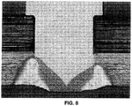
- Fig. 8 depicts another cross-sectional photograph of a laser-welded joint.
- a keyhole centre that is shifted outwards from the centre of the pin.
- On the right side of the pin where the weld is not performed though the whole pin/metal plate interface, a notch is visible.
- On the left side of the pin the keyhole is well centred, but the welding depth also does not cover the whole metal pin/metal plate interface.
Description
- The present invention relates to a method for the manufacture of a joint between a metal structure and a plastic composite structure and to an assembly comprising a metal structure and a plastic composite structure which are joined together by means of laser welding.
- In automotive engineering and other industries, the need for lightweight construction and cost efficiency is leading to the development of hybrid components in which two or more different materials are combined. Fiber reinforced plastic (FRP) composites are superior to metals in terms of specific strength and stiffness, corrosion resistance, and formability. Composite materials, therefore, are used for primary structures of small or mid-sized nautical vessels and aerospace structures. However, metals are still important materials especially for large structures. Therefore, large vessels are usually made of hybrid structures composed of composites and metals. Since composite/metal hybrid structures are the key technology in realizing high stiffness, light weight, and high reliability, they are now seen in many structures: automotive drive shafts, headstocks of grinding machines, and robotic structures.
- There are two major methods for joining different materials: mechanical fastening and adhesive bonding. Mechanical fastening using bolts or rivets is simple, and it is possible to obtain high joining strength with small scatter. This method is therefore widely used in metal structures. The disadvantages of mechanical joints are an increase in weight of the whole structure and low sealing performance. In addition, presence of the bolt holes of mechanical joints decreases the cross-sectional area of structures, and increases stress concentration. Especially in the case of the FRP structures, plastic-metal hybrid structures, the drilling process to fabricate bolt holes breaks reinforcing fibers, and causes peeling of the higher plies at the entry of the hole, fiber wrenching and resin degradation on the wall of the hole, and delamination of the last plies in the laminate. Since these damages can initiate fatigue cracks, mechanical fastening in FRP structures severely decreases fatigue strength. For these reasons, a higher number of bolted joints has to be used to join a FRP structure and a metal sheet in applications requiring durable joints, such as in the aircraft industry. A bolted and co-cured hybrid joint between glass fiber reinforced plastic (GFRP) and aluminium is disclosed in Matsuzaki et al., Composites: Part A 39 (2008), pages 154-163.
- Using adhesive bonding, the weight of a structure is less than if mechanical joints are used. The adhesive joint has a sealing effect, no stress concentration due to bolt holes, and no damage in the FRP from the bonding process. These advantages allow the adhesive joints to have high fatigue strength. In the adhesive joints, however, each adherend has its own suitable adhesive. The selection of adhesive is difficult for joints of different materials. In addition, degreasing and etching are necessary in order to obtain high joining strength during the general bonding process of metal adherends. Although chemical treatment brings high bonding strength, the adhesive surface would be oxidized and polluted after a few hours. The degradation of the adhesive surface highly decreases the bonding strength. For these reasons, obtaining high joint strength with low scatter is difficult for adhesive joints.
- Hence, there is a continued need for improved methods for joining metal and plastic composite structures.
- For example,
WO 2008/110835 discloses a hybrid joint incorporating small diameter pins which are fitted into a plastic prepeg.DE 10 2008 031 121 A1 discloses a weld rivet connection of one or more components comprising a base component, wherein the component or components have a hole through which the shaft of the weld rivet comprising a head extends, wherein one end surface of the shaft is welded to the surface of the base component and is plastically deformed. - It is an object of the present invention to provide a method for the manufacture of a lightweight joint between a metal structure and a plastic composite structure which exhibits improved fatigue properties, and which are easy to repair, when damage occurs to the metal parts. It is a further object of the invention to provide an assembly comprising lightweight joint between a metal structure and a plastic composite structure which exhibits improved fatigue properties.
- The above mentioned object is achieved by a method for the manufacture of a joint between a plastic composite structure and a metal structure, wherein (i) at least part of the plastic composite structure is overlapped with at least part of the metal structure, (ii) a cylindrical metal rivet, which has a cylindrical shaft section and a head section, the head section having a larger diameter than the cylindrical shaft section section, is protruded through a punch or drilled hole in said plastic composite structure and said metal structure connecting both in such a way that the head section of the metal rivet faces the free surface of said plastic composite structure and that at least part of the shaft section of the metal rivet contacts the metal structure, and thereafter, (iii) the part of said metal rivet contacting said metal structure is welded to said metal structure by means of laser welding on the interface of said metal rivet and said metal structure. Preferably, part of the head portion of the cylindrical metal rivet forms a ring section which provides a bearing surface to secure the plastic composite structure against the metal structure. Alternatively, the plastic composite structure may be sandwiched between two metal structures, whereby the metal rivet is welded to both metal structures. In this way, the plastic composite structure is secured against both metal structures.
- Generally, the metal structure is of any metal or metal alloy that has good weldability to the metal or alloy that is used for the metal rivet. According to a preferred aspect of the invention, the metal structure is of titanium (Ti), aluminium (Al), magnesium (Mg) or an alloy of the afore-mentioned metals. An alloy of the afore-mentioned metals are preferably alloys, wherein any of these metals is present in an amount of not less than 50 wt.%, preferably not less than 75 wt.%.
- Preferably the metal structure is in the form of a metal sheet. A typical thickness of the metal sheet for applications in the aerospace industry is from 1 mm to 5 mm, preferably from 2 mm to 3 mm. For other applications in the aerospace, automotive or nautical vessel industries the sheet thickness can vary between 1 mm to 1 cm, preferably from 2 mm to 5 mm, and most preferably from 2 mm to 3 mm, such as 2.5 mm.
- To better adhere to the plastic composite sheet, the metal sheet may be structured on the surface facing the plastic composite sheet. The structures may be of any design which causes friction and/or which anchors the metal structure to the plastic composite structure once hardened. The configuration of the structured surface of the metal sheet may be inform of pyramids, hemispheres, or mushroom-like structures such as those described in
EP 2 648 436 A1 , which is incorporated herein by reference.
According to another preferred aspect of the invention, the plastic composite is a fiber reinforced plastic (FRP) composite, preferably of a carbon fiber reinforced plastic (CFRP) or of a glass fiber reinforced plastic (GFRP). According to a preferred aspect of the invention, the plastic composite structure is in the form of a plastic composite sheet. A typical thickness is from 1 mm to 1 cm, preferably from 2 mm to 5 mm, and most preferably from 2 mm to 3 mm, such as 2.5 mm. However, the non-welded sheet can be of any other material such as plastic, wood, glass, another metal, etc. - The metal rivet can be of any material which may be welded to the metal structure by means of laser welding. According to one aspect of the invention, the metal rivet is made of the material of the metal sheet or of a similar material. Thus, according to a preferred aspect of the invention, the metal rivet is of titanium (Ti), aluminium (Al), magnesium (Mg) or an alloy of the metals. An alloy of the afore-mentioned metals are preferably alloys, wherein any of these metals is present in an amount of not less than 50 wt.%, preferably not less than 75 wt.%.
- According to one aspect of the invention the head section of the metal rivet has a conical form that tapers from one end of the rivet to a section, where the head section connects to the shaft section of the rivet. According to another aspect of the invention the head section of the metal rivet has an undercut, i.e. the head section has a cylindrical or hemispherical form which is larger in diameter than the shaft section.
- The metal rivet may be a massive (solid) or a hollow metal rivet.
- The diameter of the metal rivet at its broadest point can vary from few micrometers to a number of centimetres. Most preferably, the metal rivet has a diameter from 2 mm to 10 mm, in particular from 4 mm to 6 mm.
- According to a further preferred embodiment of the invention, a thermal insulator layer is disposed between the metal structure and the plastic composite structure. The thermal insulator layer delays heat transfer from the metal rivet to the plastic composite in a way that burning, melting or deforming of the plastic composite is avoided when the rivet is welded to the metal sheet. Any material that can absorb the energy induced by the laser and which withstands the heat caused by the laser can be used as a thermal insulator. Preferred insulators are ceramics which have very good insulation properties. However, these materials have the disadvantage that they are very brittle. Other preferred thermal insulators are made of quartz, alumina or zirconia. Preferably, the thermal insulator layer is disposed only a few mm (such as 0.1 to 1.5 mm) around the holes through which the metal rivet is protruded, and not throughout the entire plastic composite, metal interface.
- The sheet thickness of the thermal insulator depends on the joining area structure as well as the amount of heat that is called to absorb. For weight reasons it should be chosen as thin as possible. For example the sheet thickness of the thermal insulator may be between 0.1 mm and 2 mm, preferably between 1 and 1.5 mm.
- It is preferred that the laser welded joint between metal structure and metal rivet covers the entire depth of the metal structure, i.e. metal rivet is welded to the metal structure throughout the entire thickness of the metal structure. In this way weak spots on the interface between metal rivet and metal structure are avoided, which may be the cause for crack initiation. Hence, if the laser cannot be adjusted in a manner sufficiently precise to avoid contact with the plastic composite structure, the use of the afore-mentioned thermal insulator layer on the interface between plastic composite sheet and metal sheet is recommended. On the other hand, a thermal insulator may not be necessary, if a laser is used for producing the laser welded joint, the depth of which can be adjusted in the region of few micrometers.
- The welding parameters will have to be adjusted depending on the laser equipment and the welding depth that is desired to be achieved. These parameters may differ when using different laser equipment. A person skilled in the art would know how to adjust the welding parameters. In a typical process of the invention, a laser power of around 1800 W was applied. Furthermore, in order to lower the amount of heat transferred onto the plastic composite structure during the welding procedure, the structure is preferably cooled on the side of the plastic composite.
- Other welding parameters, which may be controlled, are the welding depth. The welding depth is preferably as deep as the thickness of the metal plate or structure. The whole interface of the metal rivet and the metal structure is preferably welded, and the welded zone preferably does not have any pores or notches. The keyhole width is preferably chosen as narrow as possible, so that the welded zone and the corresponding heat affected zone are as narrow as possible. This way, the damage to the composite plate is as minimal as possible.
- A very high power laser weld can offer a high depth welded area, but care should be taken that pore creation is eliminated. Without the use of a thermal insulator, a high power laser weld can also cause irreversible damage to a composite (a duroplastic composite for example) without the use of a thermal insulator. A thermoplastic composite can endure high temperatures without significant irreversible damage and for these cases a higher laser power weld may be appropriate, even without the use of an insulator.
- Another parameter that may be controlled in the welding process is the welding path. When the metal rivet has a certain, precise diameter, the welding path is preferably adjusted, so that the centre of the welding keyhole meets exactly the interface of the metal rivet and the metal structure. When the welding path is shifted towards the centre of the rivet, the interface may not be completely welded and notches may be inserted to the weld. Notches could be points of crack initiation which reduce the fatigue life of a structure. When the welding path is shifted outwards from the centre of the rivet, notches may also be introduced to the structure.
- Preferably a single mode fibre laser having a very good beam quality is used for welding, which can provide a good joint performance together with a very small damage of the plastic composite.
- The afore-mentioned object is also achieved by an assembly of a plastic composite structure and a metal structure, wherein the plastic composite structure and the metal structure are connected by a cylindrical metal rivet, the metal rivet protruding through a hole in said plastic composite structure and said metal structure, and comprising a head section and a cylindrical shaft section, the head section being of a larger diameter than the shaft section, said connection being in such a way that the head section faces the free surface of said plastic composite structure and that at least part of the shaft section contacts the metal structure and wherein the metal rivet is joined to the metal structure by a laser welding joint. The assembly is preferably part of an aircraft, a nautical vessel or an automotive.
- Alternatively, the afore-mentioned object is achieved by an assembly of a plastic composite structure which is disposed (sandwiched) between two metal structures, and the plastic composite structure and the metal structures are connected by a cylindrical metal pin, the metal pin protruding through a hole in said plastic composite structure and said metal structures comprising only a cylindrical shaft section of which is uniform in diameter, said connection being in such a way that at least part of the cylindrical shaft section of the metal pin contacts both metal structures, and the metal pin is joined to each of the metal structures a laser weld joint. The assembly is preferably part of an aircraft, a nautical vessel or an automotive.
- The fatigue resistance is improved because the metal plate has no weak points suitable for crack initiation; the laser welding creates an integrated structure, where the metal rivet or metal pin that connects the composite part to the metal, is welded completely to the metal structure. The failure mechanism of the structure changes with the use of this invention shifting the failure from the metal structure to the metal rivets ort metal pins, which are then, easier and cost effective to replace in comparison to the whole metal structure.
- The invention is further illustrated by the appended figures, wherein:
-
Fig. 1 is a plan view of an assembly according to one embodiment of the invention; -
Fig. 2 is a cross-sectional view through an assembly according to another embodiment of the invention, -
Fig. 3 is a cross-sectional view through an assembly according to another embodiment of the invention; -
Fig. 4 is a plan view of an assembly according to another embodiment of the invention; and -
Fig. 5 is a plan view of an assembly according to a still another embodiment of the invention. -
Fig. 6 is a cross-sectional view through an assembly according to a still another embodiment of the invention. -
Fig. 7 is a cross-sectional photograph depicting a welding joint. -
Fig. 8 is a cross-sectional photograph depicting another welding joint. -
Fig. 1 depicts anassembly 10 comprising a plasticcomposite sheet 11 and ametal sheet 12 that overlaps the bottom surface of the plasticcomposite sheet 11. The plasticcomposite sheet 11 and themetal sheet 12 are joined in their overlapping region by cylindrical metal rivets 14. The cylindrical metal rivets 14 have a top section which adheres to the top surface of the plasticcomposite sheet 11. Therivets 14 may be positioned in rows of single or multiple rivets as viewed in the plan view. -
Fig. 2 depicts a similar assembly as shown inFig.1 in a cross-sectional view. Theassembly 20 depicted inFig. 2 also comprises a plasticcomposite sheet 21 and a metal sheet 22 that overlaps the bottom surface of the plasticcomposite sheet 21. The plasticcomposite sheet 21 and the metal sheet 22 are joined in their overlapping region by cylindrical metal rivets 24. The cylindrical metal rivets 24 have ahead portion 25 which is larger in diameter than theshaft portion 26 of therivet 24. In the depicted case, the rivet has an undercut in form of aring portion 27 which separates itshead portion 25 from itsshaft portion 26, and which secures the plasticcomposite sheet 21 to the metal sheet 22. Thecylindrical metal rivet 24 is attached to the metal sheet 22 by means of laser welded joints 28. -
Fig. 3 depicts an alternative embodiment of an assembly according to the invention. Theassembly 30 depicted inFig. 3 comprises a plasticcomposite sheet 31 and ametal sheet 32 that overlaps the top surface of the plasticcomposite sheet 31. The plasticcomposite sheet 31 and themetal sheet 32 are joined in their overlapping region by cylindrical metal rivets 34. The cylindrical metal rivets 34 have ahead portion 35 which is larger in diameter than theshaft portion 36 of the rivet 34. In the depicted case, thehead portion 35 of the rivet 34 has a conical form. It tapers from the bottom end of the rivet 34 to a section, where thehead section 35 connects to theshaft section 36 of the rivet 34, thereby also forming aring portion 37 which separates itshead portion 35 from itsshaft portion 36, and which secures the plasticcomposite sheet 31 to themetal sheet 32. The cylindrical metal rivet 34 is attached to themetal sheet 32 by means oflaser welding 38. -
Figs. 4 and 5 depict further alternative embodiments of assemblies (40, 50) according to the invention. The assemblies (40, 50) comprise a plastic composite sheet (41, 51) and a metal sheet (42, 52) that overlaps the top surface of the plastic composite sheet (41, 51). The plastic composite sheet (41, 51) and the metal sheet (42, 52) are joined in their overlapping region by cylindrical metal rivets (44, 54), the bottom section thereof being visible. The cylindrical metal rivets (44, 54) are attached to the metal sheet (42, 52) by means of laser welding (48, 58).Figs. 4 and 5 are distinguished by the arrangement of the metal rivets on the surface of the metal sheet (42, 52). The rivets (44, 54) may be positioned in rows of single (Fig. 4 ) or multiple rivets (Fig. 5 ) as viewed in the plan view. -
Fig. 6 depicts a further alternative embodiment of an assembly (60) according to the invention. The assemblies (60) comprises a plastic composite sheet (61) and a two metal sheets (62) that overlap the top and bottom surface of the plastic composite sheet (61), respectively in a manner that the plastic composite sheet is disposed between the two metal sheets. The plastic composite sheet (61) and the metal sheets (62) are joined in their overlapping region by cylindrical metal rivets (64). The cylindrical metal rivets (64) are attached to each metal sheet (62) by means of laser welding, where (68) depicts the laser weld. - The above figures do not illustrate the insulator, which will be a further sheet or layer disposed between the plastic composite sheet (11, 21, 31, 41, 51, 61) and the metal sheet (12, 22, 32, 42, 52, 62) in the above figures.
-
Fig. 7 depicts a cross-sectional photograph of a laser-welded joint where a high laser power was used; there are some pores visible on the keyhole area of the weld. The right side of the pin also shows an example of an outwards shifted keyhole centre. It is also obvious that part of the composite that is used here is damaged by the heat. -
Fig. 8 depicts another cross-sectional photograph of a laser-welded joint. On this picture, there is an example of a keyhole centre that is shifted outwards from the centre of the pin. On the right side of the pin, where the weld is not performed though the whole pin/metal plate interface, a notch is visible. On the left side of the pin, the keyhole is well centred, but the welding depth also does not cover the whole metal pin/metal plate interface.
Claims (15)
- Method for the manufacture of a joint between a plastic composite structure (11, 21, 31, 41, 51) and a metal structure (12, 22, 32, 42, 52), wherein (i) at least part of the plastic composite structure (11, 21, 31, 41, 51) is overlapped with at least part of the metal structure (12, 22, 32, 42, 52), (ii) a cylindrical metal rivet (14, 24, 34, 44, 54) having a head section (25, 35) and a shaft section (26, 36), the head section (25, 35) being of a larger diameter than the shaft section (26, 36), is protruded through a hole in said plastic composite structure (11, 21, 31, 41, 51) and said metal structure (12, 22, 32, 42, 52) connecting said plastic composite structure and said metal structure in such a way that the head section (25, 35) of the cylindrical metal rivet (14, 24, 34, 44, 54) faces a free surface of said plastic composite structure (11, 21, 31, 41, 51) and that the at least part of the shaft section (26, 36) of the cylindrical metal rivet (14, 24, 34, 44, 54) contacts the metal structure (12, 22, 32, 42, 52), and thereafter, (iii) the part of said metal rivet (14, 24, 34, 44, 54) contacting said metal structure (12, 22, 32, 42, 52) is welded to said metal structure (12, 22, 32, 42, 52) on the interface of said metal rivet and said metal structure, characterized in that the head section (25, 35) is protruded through a hole in said plastic composite structure and said metal structure and in that the welding occurs by means of laser welding.
- Method according to claim 1, wherein the head section (35) of the metal rivet (34) has a conical form that tapers from one end of the rivet to a section, where the head (35) section connects to the shaft section (36) of the rivet (34).
- Method according to claim 1, wherein the head section (25) of the metal rivet (24) has an undercut.
- Method according to any of claims 1 to 3, wherein the metal rivet (14, 24, 34, 44, 54) is hollow.
- Method according to any of the previous claims, wherein the metal structure (12, 22, 32, 42, 52) and the plastic composite structure (11, 21, 31, 41, 51) and the metal rivet (14, 24, 34, 44, 54) are bonded together by an adhesive before the laser welding is performed.
- Method according to any of claims 1 to 5, wherein a thermal insulator is disposed between the metal structure (12, 22, 32, 42, 52) and the plastic composite structure (11, 21, 31, 41, 51).
- Method according to claim 6, wherein the thermal insulator is of a ceramic material, quartz, alumina or zirconia.
- Method according to any of the preceding claims, wherein the material of the metal structure (12, 22, 32, 42, 52) is selected from the group consisting of titanium (Ti), aluminium (Al), magnesium (Mg) or an alloy of the afore-mentioned metals.
- Method according to any of the preceding claims, wherein the material of the plastic composite structure (11, 21, 31, 41, 51) is selected from the group consisting of carbon fiber reinforced plastic (CFRP) or of a glass fiber reinforced plastic (GFRP).
- Assembly of a plastic composite structure (11, 21, 31, 41, 51) and a metal structure (12, 22, 32, 42, 52), wherein the plastic composite structure and the metal structure are connected by a cylindrical metal rivet (14, 24, 34, 44, 54), the metal rivet (14, 24, 34, 44, 54) comprising a head section (25, 35) and a shaft section (26, 36), the head section (25, 35) being of a larger diameter than the shaft section (26, 36), characterized in that the metal rivet (14,24,34,44,54) protrudes through a hole in said plastic composite structure (11,21,31,41,51) and said metal structure (12,22,32,42,52), and in that said connection is such that the at least part of the shaft section (26, 36) of the rivet (14, 24, 34, 44, 54) contacts the metal structure (12, 22, 32, 42, 52) and wherein the metal rivet (14, 24, 34, 44, 54) and the metal structure (12, 22, 32, 42, 52) are joined by a laser welding joint in a way that the leaser welding has created an integrated structure, where the metal rivet is welded to the metal structure (12, 22, 32, 42, 52).
- Assembly according to claim 10, wherein the metal rivet is massive.
- Assembly according to any of claims 10 or 11, wherein the assembly is part of an aircraft, a nautical vessel or an automotive.
- Assembly (60) of a plastic composite structure (61) which is disposed (sandwiched) between two metal structures (62), and characterized in that the plastic composite structure (61) and the metal structures (62) are connected by a cylindrical metal pin (64), the metal pin (64) protruding through a hole in said plastic composite structure (61) and said metal structures (62), and comprising only a cylindrical shaft section of which is uniform in diameter, said connection being in such a way that part of the cylindrical shaft section of the metal pin (64) contacts both metal structures (62), and the metal pin (64) is joined to each of the metal structures (62) a laser weld joint (68) in a way that the leaser welding has created an integrated structure, where the metal pin is welded to the metal structures (62).
- Assembly according to claim 13, wherein the metal rivet is massive.
- Assembly according any of claims 13 or 14, wherein the assembly is part of an aircraft, a nautical vessel or an automotive.
Priority Applications (3)
| Application Number | Priority Date | Filing Date | Title |
|---|---|---|---|
| PT121806178T PT2698224T (en) | 2012-08-16 | 2012-08-16 | Method for the manufacture of a joint between a metal structure and a plastic composite structure |
| EP12180617.8A EP2698224B1 (en) | 2012-08-16 | 2012-08-16 | Method for the manufacture of a joint between a metal structure and a plastic composite structure |
| ES12180617.8T ES2623228T3 (en) | 2012-08-16 | 2012-08-16 | Method for the production of a joint between a metal structure and a composite plastic structure |
Applications Claiming Priority (1)
| Application Number | Priority Date | Filing Date | Title |
|---|---|---|---|
| EP12180617.8A EP2698224B1 (en) | 2012-08-16 | 2012-08-16 | Method for the manufacture of a joint between a metal structure and a plastic composite structure |
Publications (2)
| Publication Number | Publication Date |
|---|---|
| EP2698224A1 EP2698224A1 (en) | 2014-02-19 |
| EP2698224B1 true EP2698224B1 (en) | 2017-03-08 |
Family
ID=46704477
Family Applications (1)
| Application Number | Title | Priority Date | Filing Date |
|---|---|---|---|
| EP12180617.8A Not-in-force EP2698224B1 (en) | 2012-08-16 | 2012-08-16 | Method for the manufacture of a joint between a metal structure and a plastic composite structure |
Country Status (3)
| Country | Link |
|---|---|
| EP (1) | EP2698224B1 (en) |
| ES (1) | ES2623228T3 (en) |
| PT (1) | PT2698224T (en) |
Cited By (1)
| Publication number | Priority date | Publication date | Assignee | Title |
|---|---|---|---|---|
| CN107917125A (en) * | 2016-10-11 | 2018-04-17 | 张跃 | A kind of jointing of non-metal board |
Families Citing this family (9)
| Publication number | Priority date | Publication date | Assignee | Title |
|---|---|---|---|---|
| DE102014204778A1 (en) * | 2014-03-14 | 2015-09-17 | Volkswagen Aktiengesellschaft | Method for joining a steel part with a fiber-reinforced plastic part by means of a connecting element |
| GB2533429A (en) * | 2014-12-19 | 2016-06-22 | Airbus Operations Ltd | A metallic-composite joint |
| JP7012205B2 (en) * | 2016-03-30 | 2022-01-28 | パナソニックIpマネジメント株式会社 | Joined structure |
| JP6906145B2 (en) | 2016-03-30 | 2021-07-21 | パナソニックIpマネジメント株式会社 | Joint structure |
| DE102016208701A1 (en) * | 2016-05-20 | 2017-11-23 | Volkswagen Aktiengesellschaft | Method for the mechanical fastening of a connection means, connection system and motor vehicle |
| DE102016213621A1 (en) * | 2016-07-25 | 2018-01-25 | Bayerische Motoren Werke Aktiengesellschaft | Method for welding at least three components |
| CN106583627B (en) * | 2016-12-22 | 2018-07-31 | 东方电气集团东方汽轮机有限公司 | A kind of sandwich metallic plate material and its riveting molding method |
| CN108838543B (en) * | 2018-07-09 | 2020-09-29 | 大连理工大学 | Welding-riveting composite connection method for metal material and resin-based composite material |
| CN112404712A (en) * | 2019-08-20 | 2021-02-26 | 南京航空航天大学 | Gas cooling device and method for laser connection of thermoplastic composite material and metal |
Family Cites Families (5)
| Publication number | Priority date | Publication date | Assignee | Title |
|---|---|---|---|---|
| DE10111567A1 (en) * | 2001-03-10 | 2002-09-26 | Daimler Chrysler Ag | Weldable multilayer sandwich structured component, for vehicle construction, comprises metal plates on both sides of a smaller plastic core layer leaving free metal edges for welding |
| GB0704753D0 (en) | 2007-03-13 | 2007-04-18 | Airbus Uk Ltd | Preparation of a component for use in a joint |
| DE102008031121A1 (en) * | 2008-05-06 | 2009-11-12 | Daimler Ag | Schweißnietverbindung |
| US8250728B2 (en) * | 2008-07-28 | 2012-08-28 | GM Global Technology Operations LLC | Method of joining with self-piercing rivet and assembly |
| PT2468436E (en) | 2010-12-16 | 2013-07-10 | Helmholtz Zentrum Geesthacht | Method for manufacturing metal casings with structured surfaces |
-
2012
- 2012-08-16 PT PT121806178T patent/PT2698224T/en unknown
- 2012-08-16 EP EP12180617.8A patent/EP2698224B1/en not_active Not-in-force
- 2012-08-16 ES ES12180617.8T patent/ES2623228T3/en active Active
Non-Patent Citations (1)
| Title |
|---|
| None * |
Cited By (1)
| Publication number | Priority date | Publication date | Assignee | Title |
|---|---|---|---|---|
| CN107917125A (en) * | 2016-10-11 | 2018-04-17 | 张跃 | A kind of jointing of non-metal board |
Also Published As
| Publication number | Publication date |
|---|---|
| ES2623228T3 (en) | 2017-07-10 |
| EP2698224A1 (en) | 2014-02-19 |
| PT2698224T (en) | 2017-04-27 |
Similar Documents
| Publication | Publication Date | Title |
|---|---|---|
| EP2698224B1 (en) | Method for the manufacture of a joint between a metal structure and a plastic composite structure | |
| US5862975A (en) | Composite/metal structural joint with welded Z-pins | |
| JP6411993B2 (en) | Dissimilar material joint structure | |
| US7498543B2 (en) | Method for joining or repairing metal surface parts | |
| Kubit et al. | Refill friction stir spot welding of 7075-T6 aluminium alloy single-lap joints with polymer sealant interlayer | |
| JP4591547B2 (en) | CONNECTED BODY AND METHOD FOR PRODUCING THE SAME | |
| US20130149501A1 (en) | Method for connecting a fibre composite component to a structural component of an aircraft and spacecraft and a corresponding arrangement | |
| AU2013336416B2 (en) | Hybrid joint manufacturing | |
| JP2009501634A (en) | Method for joining at least two sheet-like formed bodies, in particular at least two metal sheets for lightweight structures, joints and lightweight structures | |
| EP2492083B1 (en) | Joint structure for fiber reinforced resin and metal, and joining method for fiber reinforced resin and metal | |
| EP3061684B1 (en) | Method of joining panels for an airframe | |
| EP3078480B1 (en) | Method for connecting a surface-structured workpiece and a plastic workpiece | |
| NO319176B1 (en) | Structural assembly and method of manufacturing a structural assembly | |
| US8397976B2 (en) | Method for cohesively bonding metal to a non-metallic substrate using capacitors | |
| EP2754546B1 (en) | Joining of titanium and titanium alloys to carbon fibres and carbon-fibre reinforced polymer components by ultrasonic welding | |
| US8722201B2 (en) | Connections between a monolithic metal component and a continuous-fiber reinforced laminate component, and method for production of the same | |
| Woizeschke et al. | Recent developments for laser beam joining of CFRP-aluminum structures | |
| JP5560121B2 (en) | Joining method of carbon fiber reinforced thermoplastic resin composite | |
| Joesbury | New approaches to composite metal joining | |
| EP2636509A2 (en) | Joint structure for fiber reinforced resin and metal, and joining method for fiber reinforced resin and metal | |
| EP2722531A1 (en) | Hybrid joint manufacturing | |
| Woizeschke et al. | Fracture analysis of competing failure modes of aluminum-CFRP joints using three-layer titanium laminates as transition | |
| EP3659736B1 (en) | Method to join materials with a different melting temperature | |
| US9889633B2 (en) | Attachment method for laminate structures | |
| Woizeschke et al. | Joining of aluminum and CFRP parts using titanium foils as transition elements |
Legal Events
| Date | Code | Title | Description |
|---|---|---|---|
| 17P | Request for examination filed |
Effective date: 20120816 |
|
| AK | Designated contracting states |
Kind code of ref document: A1 Designated state(s): AL AT BE BG CH CY CZ DE DK EE ES FI FR GB GR HR HU IE IS IT LI LT LU LV MC MK MT NL NO PL PT RO RS SE SI SK SM TR |
|
| AX | Request for extension of the european patent |
Extension state: BA ME |
|
| PUAI | Public reference made under article 153(3) epc to a published international application that has entered the european phase |
Free format text: ORIGINAL CODE: 0009012 |
|
| 17Q | First examination report despatched |
Effective date: 20160504 |
|
| GRAP | Despatch of communication of intention to grant a patent |
Free format text: ORIGINAL CODE: EPIDOSNIGR1 |
|
| INTG | Intention to grant announced |
Effective date: 20161214 |
|
| GRAS | Grant fee paid |
Free format text: ORIGINAL CODE: EPIDOSNIGR3 |
|
| GRAA | (expected) grant |
Free format text: ORIGINAL CODE: 0009210 |
|
| RIN1 | Information on inventor provided before grant (corrected) |
Inventor name: KASHAEV, NIKOLAI Inventor name: KOLOSSA, SPYRIDOULA Inventor name: RIEKEHR, STEFAN Inventor name: SCHNUBEL, DIRK Inventor name: VENTZKE, VOLKER Inventor name: DINSE, RENE |
|
| AK | Designated contracting states |
Kind code of ref document: B1 Designated state(s): AL AT BE BG CH CY CZ DE DK EE ES FI FR GB GR HR HU IE IS IT LI LT LU LV MC MK MT NL NO PL PT RO RS SE SI SK SM TR |
|
| REG | Reference to a national code |
Ref country code: GB Ref legal event code: FG4D |
|
| REG | Reference to a national code |
Ref country code: CH Ref legal event code: EP Ref country code: AT Ref legal event code: REF Ref document number: 873098 Country of ref document: AT Kind code of ref document: T Effective date: 20170315 |
|
| REG | Reference to a national code |
Ref country code: SE Ref legal event code: TRGR |
|
| REG | Reference to a national code |
Ref country code: IE Ref legal event code: FG4D |
|
| REG | Reference to a national code |
Ref country code: DE Ref legal event code: R096 Ref document number: 602012029503 Country of ref document: DE |
|
| REG | Reference to a national code |
Ref country code: PT Ref legal event code: SC4A Ref document number: 2698224 Country of ref document: PT Date of ref document: 20170427 Kind code of ref document: T Free format text: AVAILABILITY OF NATIONAL TRANSLATION Effective date: 20170412 |
|
| REG | Reference to a national code |
Ref country code: ES Ref legal event code: FG2A Ref document number: 2623228 Country of ref document: ES Kind code of ref document: T3 Effective date: 20170710 Ref country code: LT Ref legal event code: MG4D |
|
| REG | Reference to a national code |
Ref country code: NL Ref legal event code: MP Effective date: 20170308 |
|
| PG25 | Lapsed in a contracting state [announced via postgrant information from national office to epo] |
Ref country code: HR Free format text: LAPSE BECAUSE OF FAILURE TO SUBMIT A TRANSLATION OF THE DESCRIPTION OR TO PAY THE FEE WITHIN THE PRESCRIBED TIME-LIMIT Effective date: 20170308 Ref country code: FI Free format text: LAPSE BECAUSE OF FAILURE TO SUBMIT A TRANSLATION OF THE DESCRIPTION OR TO PAY THE FEE WITHIN THE PRESCRIBED TIME-LIMIT Effective date: 20170308 Ref country code: LT Free format text: LAPSE BECAUSE OF FAILURE TO SUBMIT A TRANSLATION OF THE DESCRIPTION OR TO PAY THE FEE WITHIN THE PRESCRIBED TIME-LIMIT Effective date: 20170308 Ref country code: GR Free format text: LAPSE BECAUSE OF FAILURE TO SUBMIT A TRANSLATION OF THE DESCRIPTION OR TO PAY THE FEE WITHIN THE PRESCRIBED TIME-LIMIT Effective date: 20170609 Ref country code: NO Free format text: LAPSE BECAUSE OF FAILURE TO SUBMIT A TRANSLATION OF THE DESCRIPTION OR TO PAY THE FEE WITHIN THE PRESCRIBED TIME-LIMIT Effective date: 20170608 |
|
| REG | Reference to a national code |
Ref country code: AT Ref legal event code: MK05 Ref document number: 873098 Country of ref document: AT Kind code of ref document: T Effective date: 20170308 |
|
| REG | Reference to a national code |
Ref country code: FR Ref legal event code: PLFP Year of fee payment: 6 |
|
| PG25 | Lapsed in a contracting state [announced via postgrant information from national office to epo] |
Ref country code: BG Free format text: LAPSE BECAUSE OF FAILURE TO SUBMIT A TRANSLATION OF THE DESCRIPTION OR TO PAY THE FEE WITHIN THE PRESCRIBED TIME-LIMIT Effective date: 20170608 Ref country code: RS Free format text: LAPSE BECAUSE OF FAILURE TO SUBMIT A TRANSLATION OF THE DESCRIPTION OR TO PAY THE FEE WITHIN THE PRESCRIBED TIME-LIMIT Effective date: 20170308 Ref country code: LV Free format text: LAPSE BECAUSE OF FAILURE TO SUBMIT A TRANSLATION OF THE DESCRIPTION OR TO PAY THE FEE WITHIN THE PRESCRIBED TIME-LIMIT Effective date: 20170308 |
|
| PG25 | Lapsed in a contracting state [announced via postgrant information from national office to epo] |
Ref country code: NL Free format text: LAPSE BECAUSE OF FAILURE TO SUBMIT A TRANSLATION OF THE DESCRIPTION OR TO PAY THE FEE WITHIN THE PRESCRIBED TIME-LIMIT Effective date: 20170308 |
|
| PG25 | Lapsed in a contracting state [announced via postgrant information from national office to epo] |
Ref country code: SK Free format text: LAPSE BECAUSE OF FAILURE TO SUBMIT A TRANSLATION OF THE DESCRIPTION OR TO PAY THE FEE WITHIN THE PRESCRIBED TIME-LIMIT Effective date: 20170308 Ref country code: AT Free format text: LAPSE BECAUSE OF FAILURE TO SUBMIT A TRANSLATION OF THE DESCRIPTION OR TO PAY THE FEE WITHIN THE PRESCRIBED TIME-LIMIT Effective date: 20170308 Ref country code: CZ Free format text: LAPSE BECAUSE OF FAILURE TO SUBMIT A TRANSLATION OF THE DESCRIPTION OR TO PAY THE FEE WITHIN THE PRESCRIBED TIME-LIMIT Effective date: 20170308 Ref country code: RO Free format text: LAPSE BECAUSE OF FAILURE TO SUBMIT A TRANSLATION OF THE DESCRIPTION OR TO PAY THE FEE WITHIN THE PRESCRIBED TIME-LIMIT Effective date: 20170308 Ref country code: EE Free format text: LAPSE BECAUSE OF FAILURE TO SUBMIT A TRANSLATION OF THE DESCRIPTION OR TO PAY THE FEE WITHIN THE PRESCRIBED TIME-LIMIT Effective date: 20170308 |
|
| PG25 | Lapsed in a contracting state [announced via postgrant information from national office to epo] |
Ref country code: PL Free format text: LAPSE BECAUSE OF FAILURE TO SUBMIT A TRANSLATION OF THE DESCRIPTION OR TO PAY THE FEE WITHIN THE PRESCRIBED TIME-LIMIT Effective date: 20170308 Ref country code: IS Free format text: LAPSE BECAUSE OF FAILURE TO SUBMIT A TRANSLATION OF THE DESCRIPTION OR TO PAY THE FEE WITHIN THE PRESCRIBED TIME-LIMIT Effective date: 20170708 Ref country code: SM Free format text: LAPSE BECAUSE OF FAILURE TO SUBMIT A TRANSLATION OF THE DESCRIPTION OR TO PAY THE FEE WITHIN THE PRESCRIBED TIME-LIMIT Effective date: 20170308 |
|
| REG | Reference to a national code |
Ref country code: DE Ref legal event code: R097 Ref document number: 602012029503 Country of ref document: DE |
|
| PLBE | No opposition filed within time limit |
Free format text: ORIGINAL CODE: 0009261 |
|
| STAA | Information on the status of an ep patent application or granted ep patent |
Free format text: STATUS: NO OPPOSITION FILED WITHIN TIME LIMIT |
|
| PG25 | Lapsed in a contracting state [announced via postgrant information from national office to epo] |
Ref country code: DK Free format text: LAPSE BECAUSE OF FAILURE TO SUBMIT A TRANSLATION OF THE DESCRIPTION OR TO PAY THE FEE WITHIN THE PRESCRIBED TIME-LIMIT Effective date: 20170308 |
|
| 26N | No opposition filed |
Effective date: 20171211 |
|
| PG25 | Lapsed in a contracting state [announced via postgrant information from national office to epo] |
Ref country code: SI Free format text: LAPSE BECAUSE OF FAILURE TO SUBMIT A TRANSLATION OF THE DESCRIPTION OR TO PAY THE FEE WITHIN THE PRESCRIBED TIME-LIMIT Effective date: 20170308 |
|
| REG | Reference to a national code |
Ref country code: CH Ref legal event code: PL |
|
| PG25 | Lapsed in a contracting state [announced via postgrant information from national office to epo] |
Ref country code: MC Free format text: LAPSE BECAUSE OF FAILURE TO SUBMIT A TRANSLATION OF THE DESCRIPTION OR TO PAY THE FEE WITHIN THE PRESCRIBED TIME-LIMIT Effective date: 20170308 |
|
| PG25 | Lapsed in a contracting state [announced via postgrant information from national office to epo] |
Ref country code: LI Free format text: LAPSE BECAUSE OF NON-PAYMENT OF DUE FEES Effective date: 20170831 Ref country code: CH Free format text: LAPSE BECAUSE OF NON-PAYMENT OF DUE FEES Effective date: 20170831 |
|
| REG | Reference to a national code |
Ref country code: IE Ref legal event code: MM4A |
|
| REG | Reference to a national code |
Ref country code: BE Ref legal event code: MM Effective date: 20170831 |
|
| PG25 | Lapsed in a contracting state [announced via postgrant information from national office to epo] |
Ref country code: LU Free format text: LAPSE BECAUSE OF NON-PAYMENT OF DUE FEES Effective date: 20170816 |
|
| PG25 | Lapsed in a contracting state [announced via postgrant information from national office to epo] |
Ref country code: IE Free format text: LAPSE BECAUSE OF NON-PAYMENT OF DUE FEES Effective date: 20170816 |
|
| REG | Reference to a national code |
Ref country code: FR Ref legal event code: PLFP Year of fee payment: 7 |
|
| PG25 | Lapsed in a contracting state [announced via postgrant information from national office to epo] |
Ref country code: BE Free format text: LAPSE BECAUSE OF NON-PAYMENT OF DUE FEES Effective date: 20170831 |
|
| PG25 | Lapsed in a contracting state [announced via postgrant information from national office to epo] |
Ref country code: MT Free format text: LAPSE BECAUSE OF NON-PAYMENT OF DUE FEES Effective date: 20170816 |
|
| PG25 | Lapsed in a contracting state [announced via postgrant information from national office to epo] |
Ref country code: HU Free format text: LAPSE BECAUSE OF FAILURE TO SUBMIT A TRANSLATION OF THE DESCRIPTION OR TO PAY THE FEE WITHIN THE PRESCRIBED TIME-LIMIT; INVALID AB INITIO Effective date: 20120816 |
|
| PG25 | Lapsed in a contracting state [announced via postgrant information from national office to epo] |
Ref country code: CY Free format text: LAPSE BECAUSE OF NON-PAYMENT OF DUE FEES Effective date: 20170308 |
|
| PG25 | Lapsed in a contracting state [announced via postgrant information from national office to epo] |
Ref country code: MK Free format text: LAPSE BECAUSE OF FAILURE TO SUBMIT A TRANSLATION OF THE DESCRIPTION OR TO PAY THE FEE WITHIN THE PRESCRIBED TIME-LIMIT Effective date: 20170308 |
|
| PG25 | Lapsed in a contracting state [announced via postgrant information from national office to epo] |
Ref country code: TR Free format text: LAPSE BECAUSE OF FAILURE TO SUBMIT A TRANSLATION OF THE DESCRIPTION OR TO PAY THE FEE WITHIN THE PRESCRIBED TIME-LIMIT Effective date: 20170308 |
|
| PG25 | Lapsed in a contracting state [announced via postgrant information from national office to epo] |
Ref country code: AL Free format text: LAPSE BECAUSE OF FAILURE TO SUBMIT A TRANSLATION OF THE DESCRIPTION OR TO PAY THE FEE WITHIN THE PRESCRIBED TIME-LIMIT Effective date: 20170308 |
|
| PGFP | Annual fee paid to national office [announced via postgrant information from national office to epo] |
Ref country code: PT Payment date: 20200807 Year of fee payment: 9 Ref country code: FR Payment date: 20200820 Year of fee payment: 9 Ref country code: ES Payment date: 20200917 Year of fee payment: 9 Ref country code: GB Payment date: 20200825 Year of fee payment: 9 Ref country code: DE Payment date: 20200824 Year of fee payment: 9 |
|
| PGFP | Annual fee paid to national office [announced via postgrant information from national office to epo] |
Ref country code: SE Payment date: 20200825 Year of fee payment: 9 Ref country code: IT Payment date: 20200831 Year of fee payment: 9 |
|
| REG | Reference to a national code |
Ref country code: DE Ref legal event code: R119 Ref document number: 602012029503 Country of ref document: DE |
|
| REG | Reference to a national code |
Ref country code: SE Ref legal event code: EUG |
|
| GBPC | Gb: european patent ceased through non-payment of renewal fee |
Effective date: 20210816 |
|
| PG25 | Lapsed in a contracting state [announced via postgrant information from national office to epo] |
Ref country code: SE Free format text: LAPSE BECAUSE OF NON-PAYMENT OF DUE FEES Effective date: 20210817 Ref country code: PT Free format text: LAPSE BECAUSE OF NON-PAYMENT OF DUE FEES Effective date: 20220216 |
|
| PG25 | Lapsed in a contracting state [announced via postgrant information from national office to epo] |
Ref country code: IT Free format text: LAPSE BECAUSE OF NON-PAYMENT OF DUE FEES Effective date: 20210816 Ref country code: GB Free format text: LAPSE BECAUSE OF NON-PAYMENT OF DUE FEES Effective date: 20210816 Ref country code: FR Free format text: LAPSE BECAUSE OF NON-PAYMENT OF DUE FEES Effective date: 20210831 Ref country code: DE Free format text: LAPSE BECAUSE OF NON-PAYMENT OF DUE FEES Effective date: 20220301 |
|
| REG | Reference to a national code |
Ref country code: ES Ref legal event code: FD2A Effective date: 20221006 |
|
| PG25 | Lapsed in a contracting state [announced via postgrant information from national office to epo] |
Ref country code: ES Free format text: LAPSE BECAUSE OF NON-PAYMENT OF DUE FEES Effective date: 20210817 |