EP2697783B1 - Distribution of premises access information - Google Patents
Distribution of premises access information Download PDFInfo
- Publication number
- EP2697783B1 EP2697783B1 EP12710930.4A EP12710930A EP2697783B1 EP 2697783 B1 EP2697783 B1 EP 2697783B1 EP 12710930 A EP12710930 A EP 12710930A EP 2697783 B1 EP2697783 B1 EP 2697783B1
- Authority
- EP
- European Patent Office
- Prior art keywords
- premises
- server
- access
- ticket
- visitor
- Prior art date
- Legal status (The legal status is an assumption and is not a legal conclusion. Google has not performed a legal analysis and makes no representation as to the accuracy of the status listed.)
- Active
Links
- 238000000034 method Methods 0.000 claims description 52
- 230000003287 optical effect Effects 0.000 claims description 42
- 238000013475 authorization Methods 0.000 claims description 15
- 230000000153 supplemental effect Effects 0.000 claims description 11
- 238000010586 diagram Methods 0.000 description 20
- 238000005516 engineering process Methods 0.000 description 18
- 238000012790 confirmation Methods 0.000 description 5
- 238000013500 data storage Methods 0.000 description 4
- 238000013459 approach Methods 0.000 description 2
- 230000008520 organization Effects 0.000 description 2
- 238000003384 imaging method Methods 0.000 description 1
- 238000009434 installation Methods 0.000 description 1
- 238000000053 physical method Methods 0.000 description 1
- 229920001690 polydopamine Polymers 0.000 description 1
Images


Classifications
-
- G—PHYSICS
- G07—CHECKING-DEVICES
- G07C—TIME OR ATTENDANCE REGISTERS; REGISTERING OR INDICATING THE WORKING OF MACHINES; GENERATING RANDOM NUMBERS; VOTING OR LOTTERY APPARATUS; ARRANGEMENTS, SYSTEMS OR APPARATUS FOR CHECKING NOT PROVIDED FOR ELSEWHERE
- G07C9/00—Individual registration on entry or exit
- G07C9/20—Individual registration on entry or exit involving the use of a pass
- G07C9/22—Individual registration on entry or exit involving the use of a pass in combination with an identity check of the pass holder
Definitions
- This disclosure relates to the distribution of premises access information.
- Access information can be used to determine who or what can enter a premises and, for example, under what circumstances.
- the premises can comprise, for example, one or more buildings, a portion of a building, an open or semi-open area, a subterranean structure and/or an elevator installation.
- WO 2010/112586 describes a method for access control. An identification code is sent to an access code using a mobile telephone. If the identification code is recognized as valid, an access code is sent from an access node to the mobile telephone and presented on a display of the mobile telephone. The access code is detected using a camera, and if the access code is recognized as valid, the access is granted.
- premises access information can be distributed electronically (compared to, for example, distributing the access information exclusively by personal contact or by physical methods such as a delivery service). Accordingly, it can be useful to have additional technologies for electronic distribution of premises access information.
- Premises access information can be distributed using a ticket server coupled to a remotely located premises server.
- the ticket server receives a ticket request from a host device. After interacting with the premises server, the ticket server sends access-related information to a visitor device. The visitor device can later use the access-related information to gain access at a premises.
- a premises access control method comprises: receiving, from a host device and using a ticket server, an optical code access ticket request for use at a premises by a visitor device; sending, using the ticket server, an authorization request to a premises server, the ticket server being remotely located from the premises server and remotely located from the host device; and sending, using the ticket server an access link message to the visitor device, the access link message providing access to an optical code for accessing the premises.
- the access ticket request can comprise a time parameter, an entrance location parameter and a supplemental code parameter.
- the premises server can be located at the premises.
- the method can further comprise authenticating the host device, possibly for the premises,
- the promises server is configured to provide access to the premises based on the optical code and based on a supplemental code from the promises server.
- the method can further comprise sending, using the premises server, the supplemental code to the visitor device.
- the premises can comprise a plurality of entrances, the method further comprising determining that the optical code for accessing the promises has been presented at an incorrect one of the plurality of entrances.
- the premises server can record visit information associated with the optical code
- the method comprises providing visitor guidance information to the visitor device based at least in part on the optical code, the guidance information possibly including an elevator call assignment.
- the method can further comprise sending, using the ticket server, the optical code to the visitor device. Access rights associated with the optical code can be modified.
- the ticket server and the premises server can be controlled by different parties.
- a premises access control method comprises: receiving, from a first host device and using a ticket server, a request for a first optical code access ticket for use at a first premises by a first visitor device; sending, using the ticket server, a first authorization request to a first premises server located at the first premises, the ticket server being remotely located from the first premises server and remotely located from the first host device; sending, using the ticket server, a first access link message to the first visitor device, the first access link message providing access to a first optical code for accessing the first premises; receiving, from a second host device and using the ticket server, a request for a second optical code access ticket for use at a second premises by a second visitor device; sending, using the ticket server, a second authorization request to a second premises server located at the second premises, the ticket server being remotely located from the second premises server end remotely located from the second host device; and sending, using the ticket server, a second access link message to the second visitor device, the second access link message providing access to a second optical code for accessing
- the method acts disclosed herein can be performed by a processor executing instructions stored on one or more computer-readable storage media.
- the computer-readable storage media comprise, for example, one or more optical disks, volatile memory components (such as DRAM or SRAM), and/or nonvolatile memory components (such as hard drives, Flash RAM or ROM).
- volatile memory components such as DRAM or SRAM
- nonvolatile memory components such as hard drives, Flash RAM or ROM.
- the computer-readable storage media do not comprise transitory signals.
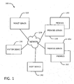
- FIG. 1 shows a block diagram of an exemplary embodiment of a system 100 for distribution of premises access information.
- premises access information generally refers to information that can be used to gain entrance to one or more portions of a premises.
- the system 100 comprises a ticket server 110, which can exchange information with one or more other system components through a network 120.
- the network 120 comprises a wired and/or wireless network (e.g., an Ethernet network, a wireless LAN network and/or the internet).
- the ticket server is remotely located from the other system components.
- communications over the network 120 are performed using various security measures. For example, data can be encrypted and/or a VPN (virtual private network) can be used.
- VPN virtual private network
- Further components can include, for example, a visitor device 130 and a host device 140.
- Each of the visitor device 130 and the host device 140 can comprise a portable electronic device configurable to execute one or more software programs, including software programs which cause the devices 130, 140 to perform one or more method acts described herein.
- Examples of the devices 130, 140 include handheld computers, smartphones, mobile telephones, tablet computers, laptop computers and PDAs.
- the host device 140 can also comprise electronic devices which are not necessarily considered to be "portable," such as desktop personal computers.
- the devices 130, 140 can be the same model of device, or they can be different models.
- the system 100 further comprises a premises server 150.
- the premises server 150 handles permission information for one or more premises 160.
- the server 150 is located at the premises 160; in other cases, the server 150 is located outside of the premises 160.
- the system 100 can further comprise one or more additional premises servers 152, which can store permission information for one or more other premises 162.
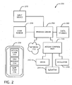
- FIG. 2 shows a block diagram of an exemplary embodiment of system 200 for controlling access to a premises.
- the system 200 comprises a premises server 250, which can be similar to the servers 150, 152 described above.
- the server 250 can communicate with other components (e.g., one or more other components described above in the system 100).
- the server 250 can read and/or write permissions data (e.g., whether a visitor should be granted access to a premises at a particular time and place) and other data.
- the server 250 is coupled to one or more code readers 220, which are designed to read single- or multi-dimensional optical codes from hardcopy documents (e.g., paper printouts) and/or from portable electronic devices.
- the reader 220 can read a two-dimensional optical code 232 that is displayed on the screen of a portable electronic device 230.
- the optical code 232 comprises a bar code, a QR code, a DataMatrix code, and/or another type of code.
- the code reader 220 generally comprises a bar code scanner, a camera and/or other imaging device.
- a link message 234 and/or a supplemental code message 236 can also be displayed and/or stored by the device 230.
- the optical code 232 stores information that allows a visitor to be associated with permissions data.
- the server 250 can be coupled to an access control unit 240.
- the access control unit 240 provides operating signals to one or more components at the premises.
- Such components can include one or more doors 242, one or more elevators 244 and/or one or more escalators 246.
- the premises comprises multiple entrances, each of the entrances comprising a door, elevator and/or escalator.
- the server 250 is also coupled to an input device 270.
- the input device 270 can comprise, for example, a keyboard or keypad, and can be used for entering additional information. Examples of such information are described below.
- the system 200 can generally be used as follows.
- a visitor having the portable electronic device 230 approaches the code reader 220 at a premises to which the visitor wishes to gain access.
- the code reader 220 reads the code 232 from the screen of the device 230 and sends the code to the premises server 250.
- the server 250 examines permission data stored in the data storage component 260 and determines whether the visitor should be granted access to the premises based on the visitor's possession of the code 232. If access is to be granted, the server 250 indicates this to the access control unit 240.
- the access control unit 240 then accordingly operates one or more components (e.g., door 242, elevator 244, escalator 246) to give the visitor the appropriate access to the premises.
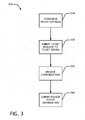
- FIG. 3 shows a block diagram of an exemplary embodiment of a method 300 for distributing premises access information.
- a host indicates one or more ticket settings or parameters using a host device (e.g., similar to the host device 140, described above).
- the ticket settings can comprise, for example: an identifier for a visitor device (e.g., telephone number, IMEI (International Mobile Equipment Identity) number, MAC (media access control) address, serial number); a date and time for access (including a specific time or one or more time ranges); a premises identifier; an entrance identifier; how often a given optical code for the visitor device can be used (e.g., once or more than once); and/or an indication of whether additional information should be required for obtaining access at the premises.
- the additional information also called "supplemental" information
- PIN personal identification number
- the ticket request is submitted to a ticket server.
- the host device receives a confirmation of the approval in a method act 330.
- information for a requested ticket can be revised in a method act 340.
- the ticket can be canceled, or one or more of the ticket settings can be changed.
- FIG. 4 shows a block diagram of an exemplary embodiment of a method 400 for distributing premises access information.
- a ticket server e.g., like the server 110 described above receives a ticket request from a host device.
- the ticket server performs an authentication of the host device. The authentication can be based on, for example, X.509 protocol and/or another protocol.
- the ticket server Based at least in part on the ticket request, the ticket server sends an authorization request to a premises server (e.g., like the premises server 150 described above) in a method act 420.
- the authentication request includes, for example, identifying information for a visitor device and details of the location and time of the requested visit. In some cases the request also indicates whether supplemental information should be required for obtaining access at the premises. In additional cases the request includes identifying information for the visitor device (e.g., a telephone number and/or e-mail address). In some embodiments, if the request is approved by the premises server, the ticket server receives a confirmation from the premises server.
- the ticket server sends the host device a confirmation that the ticket request has been approved.
- the ticket server sends a link message to the visitor device.
- the link message provides information that allows the visitor device to request an optical code that can be used in obtaining access to the premises. One or more access rights are thus associated with the optical code.
- the link message comprises a network address, such as a URL. At least a portion of the link message can be sent as an e-mail message, a text message, or a multimedia message.
- the optical code is sent to the visitor device without first sending a link message to the visitor device.
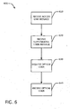
- FIG. 5 shows a block diagram of an exemplary embodiment of a method 500 for distributing premises access information.
- a premises server like the premises servers 150, 152, 250, described above receives from a ticket server a request to authorize a ticket for a visitor device.
- the authorization request can be similar to the request described above for FIG. 4 .
- the premises server compares the authorization request to permissions information (possibly stored in a device like the data storage component 260, described above). If the authorization request is allowable according to the permissions information, the premises server grants the request in a method act 520. Otherwise, the permissions server may deny the request.
- the premises server records information about the request, such as the visit time and location, and whether additional information is required from the visitor.
- the premises server if the premises server will require additional information (e.g., a supplemental code) from the visitor at the premises, the premises server sends this information to the visitor device in an access code message in a method act 540. At least a portion of the information can be sent as an e-mail message, a text message, or a multimedia message.
- additional information e.g., a supplemental code
- the premises server grants access to the visitor in a method act 550, assuming that the conditions associated with the optical code are satisfied.
- the option to require additional information from the visitor, and the option to have that information provided to the visitor by the premises server, can provide for more robust security than in a system where the additional information is not required or where both the access link message and the additional information are provided to the visitor device by the authorization server.
- the authorization server and the premises server could be controlled by two different entities (e.g., a service provider and a building owner or manager, respectively). Accordingly, requiring a visitor to present both an optical code and, for example, a PIN to obtain access can help prevent the service provider from granting access to the premises without the permission or knowledge of the building owner or manager.
- FIG. 6 shows a block diagram of an exemplary embodiment of a method 600 for receiving premises access information.
- a visitor device like the visitor device 130, described above receives an access message link.
- the link message generally provides information that allows the visitor device to request an optical code that can be used in obtaining access to the premises.
- the visitor device receives a message containing a supplemental code.
- method act 620 can occur before act 610.
- the visitor device In a method act 630, the visitor device, based at least in part on the access link message, requests an optical code from a ticket server. In a method act 640, the visitor device receives the optical code. The optical code can then be used to gain access to the premises. In at least some cases, the code is valid for a limited time after it is requested (e.g., one, five or ten minutes, or another amount of time). This can help prevent unauthorized use of the code if, for example, the visitor device is lost or stolen after the optical code is requested, but before it is presented at the premises.
- a limited time after it is requested e.g., one, five or ten minutes, or another amount of time. This can help prevent unauthorized use of the code if, for example, the visitor device is lost or stolen after the optical code is requested, but before it is presented at the premises.
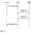
- FIG. 7 shows a signal diagram for an exemplary exchange of signals produced according to one or more embodiments of the disclosed technologies.
- the participants in this exchange include, for example, a host device (like the host device 140, described above), a ticket server (like the ticket server 110, described above), and a premises server (like the premises server 152, described above).
- the host device sends a ticket request 710 to the ticket server.
- the ticket server sends an authorization request 720 to the premises server.
- the premises server sends an authorization reply 730 to the ticket server.
- the ticket server sends a confirmation 740 of the authorization of the ticket request to the host device.
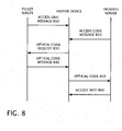
- FIG. 8 shows a signal diagram for an exemplary exchange of signals produced according to one or more embodiments of the disclosed technologies.
- the participants in this exchange include, for example, a ticket server (like the ticket server 110, described above), a visitor device (like the visitor device 130, described above), and a premises server (like the premises server 152, described above).
- the ticket server sends an access link message 810 to the visitor device.
- the premises server sends an access code message 820 to the visitor device.
- the visitor device sends to the ticket server an optical code request 830.
- the ticket server in reply sends an optical code message 840 to the visitor device.
- the visitor device then provides a message 850 with the optical code to the premises server through, for example, a code reader.
- the visitor also provides to the premises server additional information, such as a PIN code.
- the additional information can be transmitted from the visitor device to the premises server.
- the additional information is provided by the visitor through an input device, such as a keypad or keyboard.
- the premises server then sends a message 860 to the visitor device with access information.
- the access information can comprise, for example, a confirmation that access has been granted, a direction in which the visitor should travel, a distance which the visitor should travel, a door that the visitor should enter, an escalator that the visitor should take, and/or a call assignment for an elevator.
- FIGS. 7 and 8 can be read such that signals appearing toward the bottom of the figure are sent after those appearing toward the top of the figure.
- the access code message 820 can be sent to the visitor device before the access link message 810.
- FIG. 9 shows a block diagram of an exemplary embodiment of a server 900 (e.g., a ticket server, a premises server) that can be used with one or more technologies disclosed herein.
- the server comprises one or more processors 910.
- the processor 910 is coupled to a memory 920, which comprises one or more computer-readable storage media storing software instructions 930. When executed by the processor 910, the software instructions 930 cause the processor 910 to perform one or more method acts disclosed herein. Further embodiments of the server 900 can comprise one or more additional components.
- FIG. 10 shows a block diagram of an exemplary embodiment of an electronic device 1000 that can be used with one or more technologies disclosed herein, for example as a visitor device and/or a host device.
- the device 1000 comprises components such as a processor 1010.
- the processor 1010 is coupled to a memory 1020, which comprises one or more computer-readable storage media storing at least software instructions 1030.
- the software instructions 1030 When executed by the processor 1010, the software instructions 1030 cause the processor 1010 to perform one or more method acts disclosed herein.
- the software instructions 1030 can be loaded onto the device 1000 through a connection with another electronic device (e.g., a personal computer), through a connection to one or more computerreadable storage media (e.g., through a data storage card) and/or through a network connection (e.g., over the internet or a private network).
- another electronic device e.g., a personal computer
- one or more computerreadable storage media e.g., through a data storage card
- a network connection e.g., over the internet or a private network.
- the device 1000 further comprises one or more input and/or output devices, such as a display 1050 (possibly a touch-sensitive display) and an audio speaker 1060.
- a transceiver 1040 allows the device 1000 to send and receive information with one or more networks (e.g., wireless networks, wired networks).
- the one or more networks can use various technologies, for example, wireless LAN, Bluetooth, UMTS, GSM, and/or others.
- Various embodiments of the mobile device 1000 can omit one or more of the components shown in FIG. 10 and/or include additional components, including one or more further instances of any of the above components.
- a worker at an office building uses a web-based interface and his desktop computer to place a ticket order with a ticket server.
- the worker informs the ticket server that he would like a guest to be able to access the office building through the main door next Tuesday between 10:00 and 10:15 AM, and that a PIN should be required to gain access.
- the worker also provides the guest's telephone number.
- the ticket server receives this request and (after authenticating the worker's computer) sends an authorization request to the appropriate premises server.
- the premises server which is located at the office building, approves the request and records the visit information in a database.
- the ticket server sends a message to the worker's computer indicating that the request has been approved.
- the guest receives a link message on her mobile telephone indicating the time and place of her scheduled visit, along with a URL link to a QR code for accessing the office building.
- the guest also receives an SMS message from the premises server containing a PIN for accessing the building.
- the ticket server sends an image of the QR code to be used for accessing the building.
- the guest mistakenly approaches a side door of the building and uses a code reader at that door to scan the QR code, which is displayed on the screen of her telephone.
- a display at the side door informs her that she is attempting to enter at the incorrect door, since her visit is scheduled to occur through the main door.
- the display at the side door provides the guest with directions to the correct door.
- the guest scans the QR code again, this time with a code reader at that door.
- the premises server recognizes the QR code and prompts the guest to input the corresponding PIN using a nearby keypad.
- the main door opens for the guest.
- a display also indicates to the guest that the elevator destination call control system has assigned elevator B to bring her to her destination. The guest enters elevator B.
- the worker receives an SMS or e-mail message indicating that his guest has arrived.
- the message also indicates that the guest is being brought to the worker's floor using elevator B. This allows the worker to go to the proper elevator to greet the guest.
- At least some of the disclosed technologies allow for easy electronic distribution of premises access information and guidance of a visitor. The worker also knew promptly of his guest's arrival.
Description
- This disclosure relates to the distribution of premises access information.
- Access information can be used to determine who or what can enter a premises and, for example, under what circumstances. The premises can comprise, for example, one or more buildings, a portion of a building, an open or semi-open area, a subterranean structure and/or an elevator installation.
-
WO 2010/112586 describes a method for access control. An identification code is sent to an access code using a mobile telephone. If the identification code is recognized as valid, an access code is sent from an access node to the mobile telephone and presented on a display of the mobile telephone. The access code is detected using a camera, and if the access code is recognized as valid, the access is granted. - It is sometimes more convenient if premises access information can be distributed electronically (compared to, for example, distributing the access information exclusively by personal contact or by physical methods such as a delivery service). Accordingly, it can be useful to have additional technologies for electronic distribution of premises access information.
- The above issues are, in at least some cases, addressed through the technologies described in the claims.
- Premises access information can be distributed using a ticket server coupled to a remotely located premises server. The ticket server receives a ticket request from a host device. After interacting with the premises server, the ticket server sends access-related information to a visitor device. The visitor device can later use the access-related information to gain access at a premises.
- In some embodiments, a premises access control method comprises: receiving, from a host device and using a ticket server, an optical code access ticket request for use at a premises by a visitor device; sending, using the ticket server, an authorization request to a premises server, the ticket server being remotely located from the premises server and remotely located from the host device; and sending, using the ticket server an access link message to the visitor device, the access link message providing access to an optical code for accessing the premises. The access ticket request can comprise a time parameter, an entrance location parameter and a supplemental code parameter. The premises server can be located at the premises. The method can further comprise authenticating the host device, possibly for the premises, In further embodiments, the promises server is configured to provide access to the premises based on the optical code and based on a supplemental code from the promises server. The method can further comprise sending, using the premises server, the supplemental code to the visitor device. The premises can comprise a plurality of entrances, the method further comprising determining that the optical code for accessing the promises has been presented at an incorrect one of the plurality of entrances. The premises server can record visit information associated with the optical code,
- In still further embodiments, the method comprises providing visitor guidance information to the visitor device based at least in part on the optical code, the guidance information possibly including an elevator call assignment. The method can further comprise sending, using the ticket server, the optical code to the visitor device. Access rights associated with the optical code can be modified. The ticket server and the premises server can be controlled by different parties.
- In additional embodiments, a premises access control method comprises: receiving, from a first host device and using a ticket server, a request for a first optical code access ticket for use at a first premises by a first visitor device; sending, using the ticket server, a first authorization request to a first premises server located at the first premises, the ticket server being remotely located from the first premises server and remotely located from the first host device; sending, using the ticket server, a first access link message to the first visitor device, the first access link message providing access to a first optical code for accessing the first premises; receiving, from a second host device and using the ticket server, a request for a second optical code access ticket for use at a second premises by a second visitor device; sending, using the ticket server, a second authorization request to a second premises server located at the second premises, the ticket server being remotely located from the second premises server end remotely located from the second host device; and sending, using the ticket server, a second access link message to the second visitor device, the second access link message providing access to a second optical code for accessing the second promises.
- Unless stated otherwise, the method acts disclosed herein can be performed by a processor executing instructions stored on one or more computer-readable storage media. The computer-readable storage media comprise, for example, one or more optical disks, volatile memory components (such as DRAM or SRAM), and/or nonvolatile memory components (such as hard drives, Flash RAM or ROM). The computer-readable storage media do not comprise transitory signals.
- Exemplary embodiments of the disclosed technologies are described below with reference to the following figures:
-
FIG. 1 shows a block diagram of an exemplary embodiment of a system for distribution of premises access information. -
FIG. 2 shows a block diagram of an exemplary embodiment of system for controlling access to a premises. -
FIG. 3 shows a block diagram of an exemplary embodiment of a method for distributing premises access information. -
FIG. 4 shows a block diagram of an exemplary embodiment of a method for distributing premises access information. -
FIG. 5 shows a block diagram of an exemplary embodiment of a method for distributing premises access information. -
FIG. 6 shows a block diagram of an exemplary embodiment of a method for receiving premises access information. -
FIG. 7 shows a signal diagram for an exemplary exchange of signals produced according to one or more embodiments of the disclosed technologies. -
FIG. 8 shows a signal diagram for an exemplary exchange of signals produced according to one or more embodiments of the disclosed technologies. -
FIG. 9 shows a block diagram of an exemplary embodiment of a server that can be used with one or more technologies disclosed herein. -
FIG. 10 shows a block diagram of an exemplary embodiment of an electronic device that can be used with one or more technologies disclosed herein. - The term "host," as used herein, generally refers to a party that intends to have access to a premises granted to a person and/or to a machine. In various cases, the host is one or more persons, an organization or a machine (e.g., a computer or robot). The term "visitor," as used herein, generally refers to a party that receives or is intended to receive access to a premises. In various cases, the visitor is one or more persons, an organization or a machine (e.g., a computer or robot). The host and/or the visitor may or may not be an occupant of the premises. No particular level of familiarity with the premises is required of the visitor or the host.
-
FIG. 1 shows a block diagram of an exemplary embodiment of asystem 100 for distribution of premises access information. As used herein, "premises access information" generally refers to information that can be used to gain entrance to one or more portions of a premises. Thesystem 100 comprises aticket server 110, which can exchange information with one or more other system components through anetwork 120. Thenetwork 120 comprises a wired and/or wireless network (e.g., an Ethernet network, a wireless LAN network and/or the internet). In at least some cases, the ticket server is remotely located from the other system components. In at least some cases, communications over thenetwork 120 are performed using various security measures. For example, data can be encrypted and/or a VPN (virtual private network) can be used. - Further components can include, for example, a
visitor device 130 and ahost device 140. Each of thevisitor device 130 and thehost device 140 can comprise a portable electronic device configurable to execute one or more software programs, including software programs which cause thedevices devices host device 140 can also comprise electronic devices which are not necessarily considered to be "portable," such as desktop personal computers. Thedevices - The
system 100 further comprises apremises server 150. Thepremises server 150 handles permission information for one ormore premises 160. In some cases, theserver 150 is located at thepremises 160; in other cases, theserver 150 is located outside of thepremises 160. Thesystem 100 can further comprise one or moreadditional premises servers 152, which can store permission information for one or moreother premises 162. -
FIG. 2 shows a block diagram of an exemplary embodiment ofsystem 200 for controlling access to a premises. Thesystem 200 comprises apremises server 250, which can be similar to theservers network 210, theserver 250 can communicate with other components (e.g., one or more other components described above in the system 100). Using adata storage component 260, theserver 250 can read and/or write permissions data (e.g., whether a visitor should be granted access to a premises at a particular time and place) and other data. Theserver 250 is coupled to one ormore code readers 220, which are designed to read single- or multi-dimensional optical codes from hardcopy documents (e.g., paper printouts) and/or from portable electronic devices. For example, thereader 220 can read a two-dimensionaloptical code 232 that is displayed on the screen of a portableelectronic device 230. In various embodiments, theoptical code 232 comprises a bar code, a QR code, a DataMatrix code, and/or another type of code. Thecode reader 220 generally comprises a bar code scanner, a camera and/or other imaging device. As explained below, alink message 234 and/or asupplemental code message 236 can also be displayed and/or stored by thedevice 230. Theoptical code 232 stores information that allows a visitor to be associated with permissions data. - The
server 250 can be coupled to anaccess control unit 240. Theaccess control unit 240. provides operating signals to one or more components at the premises. Such components can include one ormore doors 242, one ormore elevators 244 and/or one ormore escalators 246. In particular embodiments, the premises comprises multiple entrances, each of the entrances comprising a door, elevator and/or escalator. In some embodiments, theserver 250 is also coupled to aninput device 270. Theinput device 270 can comprise, for example, a keyboard or keypad, and can be used for entering additional information. Examples of such information are described below. - In at least some cases, the
system 200 can generally be used as follows. A visitor having the portableelectronic device 230 approaches thecode reader 220 at a premises to which the visitor wishes to gain access. Thecode reader 220 reads thecode 232 from the screen of thedevice 230 and sends the code to thepremises server 250. Theserver 250 examines permission data stored in thedata storage component 260 and determines whether the visitor should be granted access to the premises based on the visitor's possession of thecode 232. If access is to be granted, theserver 250 indicates this to theaccess control unit 240. Theaccess control unit 240 then accordingly operates one or more components (e.g.,door 242,elevator 244, escalator 246) to give the visitor the appropriate access to the premises. -
FIG. 3 shows a block diagram of an exemplary embodiment of amethod 300 for distributing premises access information. In amethod act 310, a host indicates one or more ticket settings or parameters using a host device (e.g., similar to thehost device 140, described above). The ticket settings can comprise, for example: an identifier for a visitor device (e.g., telephone number, IMEI (International Mobile Equipment Identity) number, MAC (media access control) address, serial number); a date and time for access (including a specific time or one or more time ranges); a premises identifier; an entrance identifier; how often a given optical code for the visitor device can be used (e.g., once or more than once); and/or an indication of whether additional information should be required for obtaining access at the premises. The additional information (also called "supplemental" information) can comprise, for example, a personal identification number (PIN) or other piece of information that can be presented in conjunction with an optical code. - In a
method act 320, the ticket request is submitted to a ticket server. In some embodiments, if the request is approved, the host device receives a confirmation of the approval in amethod act 330. - In further embodiments, information for a requested ticket can be revised in a
method act 340. For example, the ticket can be canceled, or one or more of the ticket settings can be changed. -
FIG. 4 shows a block diagram of an exemplary embodiment of amethod 400 for distributing premises access information. In amethod act 410, a ticket server (e.g., like theserver 110 described above) receives a ticket request from a host device. In further embodiments, the ticket server performs an authentication of the host device. The authentication can be based on, for example, X.509 protocol and/or another protocol. - Based at least in part on the ticket request, the ticket server sends an authorization request to a premises server (e.g., like the
premises server 150 described above) in amethod act 420. The authentication request includes, for example, identifying information for a visitor device and details of the location and time of the requested visit. In some cases the request also indicates whether supplemental information should be required for obtaining access at the premises. In additional cases the request includes identifying information for the visitor device (e.g., a telephone number and/or e-mail address). In some embodiments, if the request is approved by the premises server, the ticket server receives a confirmation from the premises server. - In further embodiments, in a
method act 430, the ticket server sends the host device a confirmation that the ticket request has been approved. In still further embodiments, in amethod act 440, the ticket server sends a link message to the visitor device. Generally, the link message provides information that allows the visitor device to request an optical code that can be used in obtaining access to the premises. One or more access rights are thus associated with the optical code. In some embodiments, the link message comprises a network address, such as a URL. At least a portion of the link message can be sent as an e-mail message, a text message, or a multimedia message. In some cases, the optical code is sent to the visitor device without first sending a link message to the visitor device. -
FIG. 5 shows a block diagram of an exemplary embodiment of amethod 500 for distributing premises access information. In amethod act 510, a premises server (like thepremises servers FIG. 4 . The premises server compares the authorization request to permissions information (possibly stored in a device like thedata storage component 260, described above). If the authorization request is allowable according to the permissions information, the premises server grants the request in amethod act 520. Otherwise, the permissions server may deny the request. - For further embodiments, in a
method act 530, the premises server records information about the request, such as the visit time and location, and whether additional information is required from the visitor. - In still further embodiments, if the premises server will require additional information (e.g., a supplemental code) from the visitor at the premises, the premises server sends this information to the visitor device in an access code message in a
method act 540. At least a portion of the information can be sent as an e-mail message, a text message, or a multimedia message. - When the optical code (and, in some cases, the additional information) is presented to a code reader at the premises, the premises server grants access to the visitor in a
method act 550, assuming that the conditions associated with the optical code are satisfied. - The option to require additional information from the visitor, and the option to have that information provided to the visitor by the premises server, can provide for more robust security than in a system where the additional information is not required or where both the access link message and the additional information are provided to the visitor device by the authorization server. For example, in some cases the authorization server and the premises server could be controlled by two different entities (e.g., a service provider and a building owner or manager, respectively). Accordingly, requiring a visitor to present both an optical code and, for example, a PIN to obtain access can help prevent the service provider from granting access to the premises without the permission or knowledge of the building owner or manager.
-
FIG. 6 shows a block diagram of an exemplary embodiment of amethod 600 for receiving premises access information. In amethod act 610, a visitor device (like thevisitor device 130, described above) receives an access message link. As was similarly explained above, the link message generally provides information that allows the visitor device to request an optical code that can be used in obtaining access to the premises. In some embodiments, in amethod act 620 the visitor device receives a message containing a supplemental code. In particular embodiments,method act 620 can occur beforeact 610. - In a
method act 630, the visitor device, based at least in part on the access link message, requests an optical code from a ticket server. In amethod act 640, the visitor device receives the optical code. The optical code can then be used to gain access to the premises. In at least some cases, the code is valid for a limited time after it is requested (e.g., one, five or ten minutes, or another amount of time). This can help prevent unauthorized use of the code if, for example, the visitor device is lost or stolen after the optical code is requested, but before it is presented at the premises. -
FIG. 7 shows a signal diagram for an exemplary exchange of signals produced according to one or more embodiments of the disclosed technologies. The participants in this exchange include, for example, a host device (like thehost device 140, described above), a ticket server (like theticket server 110, described above), and a premises server (like thepremises server 152, described above). The host device sends aticket request 710 to the ticket server. The ticket server sends an authorization request 720 to the premises server. The premises server sends anauthorization reply 730 to the ticket server. In some cases, the ticket server sends aconfirmation 740 of the authorization of the ticket request to the host device. -
FIG. 8 shows a signal diagram for an exemplary exchange of signals produced according to one or more embodiments of the disclosed technologies. The participants in this exchange include, for example, a ticket server (like theticket server 110, described above), a visitor device (like thevisitor device 130, described above), and a premises server (like thepremises server 152, described above). The ticket server sends anaccess link message 810 to the visitor device. The premises server sends anaccess code message 820 to the visitor device. The visitor device sends to the ticket server anoptical code request 830. The ticket server in reply sends anoptical code message 840 to the visitor device. - The visitor device then provides a
message 850 with the optical code to the premises server through, for example, a code reader. Although not depicted inFIG. 8 , in some embodiments the visitor also provides to the premises server additional information, such as a PIN code. In some cases the additional information can be transmitted from the visitor device to the premises server. In other cases, the additional information is provided by the visitor through an input device, such as a keypad or keyboard. In some embodiments, the premises server then sends amessage 860 to the visitor device with access information. The access information can comprise, for example, a confirmation that access has been granted, a direction in which the visitor should travel, a distance which the visitor should travel, a door that the visitor should enter, an escalator that the visitor should take, and/or a call assignment for an elevator. - Generally,
FIGS. 7 and8 can be read such that signals appearing toward the bottom of the figure are sent after those appearing toward the top of the figure. However, in some embodiments of the disclosed technologies, other orders for sending signals are possible. For example, inFIG. 8 , theaccess code message 820 can be sent to the visitor device before theaccess link message 810. -
FIG. 9 shows a block diagram of an exemplary embodiment of a server 900 (e.g., a ticket server, a premises server) that can be used with one or more technologies disclosed herein. The server comprises one ormore processors 910. Theprocessor 910 is coupled to amemory 920, which comprises one or more computer-readable storage mediastoring software instructions 930. When executed by theprocessor 910, thesoftware instructions 930 cause theprocessor 910 to perform one or more method acts disclosed herein. Further embodiments of theserver 900 can comprise one or more additional components. -
FIG. 10 shows a block diagram of an exemplary embodiment of anelectronic device 1000 that can be used with one or more technologies disclosed herein, for example as a visitor device and/or a host device. Thedevice 1000 comprises components such as aprocessor 1010. Theprocessor 1010 is coupled to amemory 1020, which comprises one or more computer-readable storage media storing atleast software instructions 1030. When executed by theprocessor 1010, thesoftware instructions 1030 cause theprocessor 1010 to perform one or more method acts disclosed herein. Thesoftware instructions 1030 can be loaded onto thedevice 1000 through a connection with another electronic device (e.g., a personal computer), through a connection to one or more computerreadable storage media (e.g., through a data storage card) and/or through a network connection (e.g., over the internet or a private network). - The
device 1000 further comprises one or more input and/or output devices, such as a display 1050 (possibly a touch-sensitive display) and anaudio speaker 1060. Atransceiver 1040 allows thedevice 1000 to send and receive information with one or more networks (e.g., wireless networks, wired networks). The one or more networks can use various technologies, for example, wireless LAN, Bluetooth, UMTS, GSM, and/or others. - Various embodiments of the
mobile device 1000 can omit one or more of the components shown inFIG. 10 and/or include additional components, including one or more further instances of any of the above components. - In one non-limiting example scenario showing use of embodiments of one or more of the above technologies, a worker at an office building uses a web-based interface and his desktop computer to place a ticket order with a ticket server. The worker informs the ticket server that he would like a guest to be able to access the office building through the main door next Tuesday between 10:00 and 10:15 AM, and that a PIN should be required to gain access. The worker also provides the guest's telephone number. The ticket server receives this request and (after authenticating the worker's computer) sends an authorization request to the appropriate premises server. The premises server, which is located at the office building, approves the request and records the visit information in a database. The ticket server sends a message to the worker's computer indicating that the request has been approved.
- The guest receives a link message on her mobile telephone indicating the time and place of her scheduled visit, along with a URL link to a QR code for accessing the office building. The guest also receives an SMS message from the premises server containing a PIN for accessing the building.
- When the guest arrives at the building for her appointment, she uses her mobile telephone to open the link in the link message. As a result, the ticket server sends an image of the QR code to be used for accessing the building. The guest mistakenly approaches a side door of the building and uses a code reader at that door to scan the QR code, which is displayed on the screen of her telephone. A display at the side door informs her that she is attempting to enter at the incorrect door, since her visit is scheduled to occur through the main door. The display at the side door provides the guest with directions to the correct door.
- At the main door, the guest scans the QR code again, this time with a code reader at that door. The premises server recognizes the QR code and prompts the guest to input the corresponding PIN using a nearby keypad. Upon entering the required information, the main door opens for the guest. A display also indicates to the guest that the elevator destination call control system has assigned elevator B to bring her to her destination. The guest enters elevator B.
- At this time, the worker receives an SMS or e-mail message indicating that his guest has arrived. The message also indicates that the guest is being brought to the worker's floor using elevator B. This allows the worker to go to the proper elevator to greet the guest.
- As seen in this example, at least some of the disclosed technologies allow for easy electronic distribution of premises access information and guidance of a visitor. The worker also knew promptly of his guest's arrival.
- Having illustrated and described the principles of the disclosed technologies, it will be apparent to those skilled in the art that the disclosed embodiments can be modified in arrangement and detail without departing from such principles. It should be understood that features described for one or more embodiments are also intended to be used with one or more other embodiments described herein, unless explicitly stated otherwise. In view of the many possible embodiments to which the principles of the disclosed technologies can be applied, it should be recognized that the illustrated embodiments are only examples of the technologies and should not be taken as limiting the scope of the invention. Rather, the scope of the invention is defined by the following claims. We therefore claim as our invention all that comes within the claims.
Claims (13)
- A premises access control method, comprising:receiving, from a first host device (140) and using a ticket server (110), a request for a first optical code access ticket for use at a first premises (160, 162) by a first visitor device (130):sending using the ticket server (110), a first authorization request to a first premises server (150, 152, 250) located at the first premises (160, 162), the ticket server (110) being remotely located from the first promises server (150, 152, 150) and remotely located from the first host device (140), wherein the ticket server (110) and the first premises server (150, 152, 250) are controlled by different parties;sending, using the ticket server (110), a first access link message (234) to the first visitor device (130), the first access link message (234) providing access to a first optical code (232) for accessing the first premises;receiving, from a second host device (140) and using the ticket server (110), a request for a second optical code access ticket for use at a second premises (160, 162) by a second visitor device (130);sending, using the ticket server (110), a second authorization request to a second promises server (150, 152, 250) located at the second promises (160, 162), the ticket server (110) being remotely located from the second premises server (150, 152, 250) and remotely located from the second host device (140); andsending, using the ticket server (110), a second access link message (234) to the second visitor device (130), the second access link message (234) providing access to a second optical code (232) for accessing the second premises.
- The premises access control method of claim 1, wherein the first access ticket request comprises a time parameter, an entrance location parameter and a supplemental code parameter.
- The promises access control method of any of the foregoing claims, further comprising authenticating the first host device (140).
- The premises access control method of claim 3, wherein the first host device (140) is authenticated for the first premises (160, 162).
- The promises access control method of any of the foregoing claims, wherein the first premises server (150, 152, 250) is configured to provide access to the first pmmises (160, 162) based on the first optical code (232) and based on a supplemental code (236) from the first premises server (150, 152, 250).
- The premises access control method of claim 5, further comprising sending, using the first premises server (150, 152, 250), the supplemental code to the first visitor device (130),
- The premises access control method of any of the foregoing claims, wherein the first promises (160,162) comprises a plurality of entrances (242, 244, 246), the method further comprising determining that the first optical code (232) for accessing the first premises has been presented at an incorrect one of the plurality of entrances (242, 244, 246).
- The promises access control method of any of the foregoing claims, further comprising recording, using the first premises server (150, 152, 250), visit information associated with the first optical code (232).
- The premises access control method of any of the foregoing claims, further comprising providing visitor guidance information to the first visitor device (130) based at least in part on the first optical code (232).
- The premises access control method of any of the foregoing claims, further comprising sending, using the ticket server (110), the first optical code (232) to the first visitor device (130).
- The premises access control method of any of the foregoing claims, the first and second premises servers (150, 132, 250) being remote from each other.
- One or more computer-readable storage media (920) having encoded thereon instructions which, when executed by a computer (900), cause the computer (900) to perform the premises access control method of any of claims 1-5, 10 and 11.
- A system for carrying out the premises access control method of any of claims I-II, the system comprising:a ticket server (110);a first premises server (150, 152, 230); anda second premises server(150, 152, 250), the first promises server (150, 152, 250) and the second promises server (150, 152, 250) being communicatively connected to the ticket server (110) by a network.
Priority Applications (2)
| Application Number | Priority Date | Filing Date | Title |
|---|---|---|---|
| PL12710930T PL2697783T3 (en) | 2011-03-29 | 2012-03-22 | Distribution of premises access information |
| EP12710930.4A EP2697783B1 (en) | 2011-03-29 | 2012-03-22 | Distribution of premises access information |
Applications Claiming Priority (3)
| Application Number | Priority Date | Filing Date | Title |
|---|---|---|---|
| EP11160153 | 2011-03-29 | ||
| EP12710930.4A EP2697783B1 (en) | 2011-03-29 | 2012-03-22 | Distribution of premises access information |
| PCT/EP2012/055115 WO2012130727A1 (en) | 2011-03-29 | 2012-03-22 | Distribution of premises access information |
Publications (2)
| Publication Number | Publication Date |
|---|---|
| EP2697783A1 EP2697783A1 (en) | 2014-02-19 |
| EP2697783B1 true EP2697783B1 (en) | 2014-06-11 |
Family
ID=44263046
Family Applications (1)
| Application Number | Title | Priority Date | Filing Date |
|---|---|---|---|
| EP12710930.4A Active EP2697783B1 (en) | 2011-03-29 | 2012-03-22 | Distribution of premises access information |
Country Status (11)
| Country | Link |
|---|---|
| US (2) | US9202322B2 (en) |
| EP (1) | EP2697783B1 (en) |
| CN (1) | CN103460259B (en) |
| AU (1) | AU2012234407B2 (en) |
| BR (1) | BR112013024494B1 (en) |
| CA (1) | CA2830132C (en) |
| ES (1) | ES2501516T3 (en) |
| MX (1) | MX2013011116A (en) |
| PL (1) | PL2697783T3 (en) |
| SG (1) | SG193350A1 (en) |
| WO (1) | WO2012130727A1 (en) |
Families Citing this family (27)
| Publication number | Priority date | Publication date | Assignee | Title |
|---|---|---|---|---|
| JP5679051B2 (en) * | 2011-05-18 | 2015-03-04 | 三菱電機株式会社 | Elevator control device |
| GB201216284D0 (en) * | 2012-09-12 | 2012-10-24 | Illinois Tool Works | A secure door entry system and method |
| WO2014155345A1 (en) | 2013-03-28 | 2014-10-02 | Fabtale Productions Pty Ltd | Methods and systems for connecting physical objects to digital communications |
| EP2992663B1 (en) * | 2013-04-30 | 2020-01-01 | Assa Abloy AB | Method for mobile provisioning of nfc credentials |
| US9990786B1 (en) * | 2014-01-17 | 2018-06-05 | Microstrategy Incorporated | Visitor credentials |
| CN104637133A (en) * | 2014-12-23 | 2015-05-20 | 韶关市英诺维科技设备有限公司 | Application of two-dimensional code locks in communities |
| CN104537736A (en) * | 2014-12-23 | 2015-04-22 | 韶关市英诺维科技设备有限公司 | Application of two-dimension code lock in business management |
| US9972144B2 (en) | 2015-03-24 | 2018-05-15 | At&T Intellectual Property I, L.P. | Automatic physical access |
| US10296851B2 (en) | 2015-04-11 | 2019-05-21 | At&T Intellectual Property I, L.P. | Automatic allocation of physical facilities for maximum collaboration |
| US9582841B2 (en) | 2015-03-24 | 2017-02-28 | At&T Intellectual Property I, L.P. | Location based emergency management plans |
| US9824515B2 (en) | 2015-03-24 | 2017-11-21 | At&T Intellectual Property I, L.P. | Automatic calendric physical access |
| CN105493475A (en) * | 2015-10-30 | 2016-04-13 | 深圳市奥星澳科技有限公司 | Door control method, terminal, server and access control system |
| US10492066B2 (en) * | 2015-11-13 | 2019-11-26 | Sensormatic Electronics, LLC | Access and automation control systems with mobile computing device |
| US20170169635A1 (en) * | 2015-12-10 | 2017-06-15 | Rohit Karlupia | Method and system for visitor access control management |
| WO2017203339A1 (en) * | 2016-05-27 | 2017-11-30 | ISN-Partners Ltd. | Computer implemented method for assistance |
| CN110178160B (en) * | 2017-01-23 | 2023-01-24 | 开利公司 | Access control system with trusted third party |
| MX2019008606A (en) | 2017-01-23 | 2019-09-27 | Carrier Corp | Access control system with secure pass-through. |
| US10157512B2 (en) | 2017-03-31 | 2018-12-18 | Otis Elevator Company | Group access management for visitor control |
| CN107274516A (en) * | 2017-04-19 | 2017-10-20 | 捷开通讯(深圳)有限公司 | The method and server of access registrar, intelligent terminal and storage device |
| US11436567B2 (en) | 2019-01-18 | 2022-09-06 | Johnson Controls Tyco IP Holdings LLP | Conference room management system |
| KR102281798B1 (en) * | 2019-10-07 | 2021-07-26 | 이기철 | Multiple Locks with Random Passwords |
| JP2023506552A (en) * | 2019-12-20 | 2023-02-16 | インベンテイオ・アクテイエンゲゼルシヤフト | Building system for private user communication |
| US11305964B2 (en) | 2020-07-15 | 2022-04-19 | Leandre Adifon | Systems and methods for operation of elevators and other devices |
| US20220073316A1 (en) | 2020-07-15 | 2022-03-10 | Leandre Adifon | Systems and methods for operation of elevators and other devices |
| US11319186B2 (en) | 2020-07-15 | 2022-05-03 | Leandre Adifon | Systems and methods for operation of elevators and other devices |
| KR102500602B1 (en) * | 2020-09-18 | 2023-02-17 | 파킹클라우드 주식회사 | Building entrance control system and operating method thereof |
| US20230410579A1 (en) * | 2020-11-09 | 2023-12-21 | Maximum Controls, LLC | Remote access management apparatus, system and method |
Family Cites Families (47)
| Publication number | Priority date | Publication date | Assignee | Title |
|---|---|---|---|---|
| US3501622A (en) * | 1966-04-05 | 1970-03-17 | Fmc Corp | Ticket credit accounting system |
| US3988570A (en) * | 1975-01-10 | 1976-10-26 | Endyn Industries Ltd. | Controlled access and automatic revenue reporting system |
| GB2278220A (en) * | 1993-05-19 | 1994-11-23 | Central Research Lab Ltd | Access control system |
| US6141758A (en) * | 1997-07-14 | 2000-10-31 | International Business Machines Corporation | Method and system for maintaining client server security associations in a distributed computing system |
| US6725376B1 (en) * | 1997-11-13 | 2004-04-20 | Ncr Corporation | Method of using an electronic ticket and distributed server computer architecture for the same |
| JPH11227370A (en) * | 1998-02-13 | 1999-08-24 | Neuron:Kk | Genuine/false judging system for printed matter, and lock system using the same |
| US5984051A (en) * | 1998-11-09 | 1999-11-16 | Otis Elevator Company | Remote elevator call requests with descriptor tags |
| US7363267B1 (en) * | 1999-06-03 | 2008-04-22 | The Ticket Reserve, Inc. | Contingency-based options and futures for contingent travel accommodations |
| US7257542B2 (en) * | 2000-02-16 | 2007-08-14 | Stamps.Com | Secure on-line ticketing |
| JP2001344545A (en) * | 2000-03-29 | 2001-12-14 | Ibm Japan Ltd | Processing system, server, processing terminal, communication terminal, processing method, data managing method, processing performing method and program |
| US6760841B1 (en) * | 2000-05-01 | 2004-07-06 | Xtec, Incorporated | Methods and apparatus for securely conducting and authenticating transactions over unsecured communication channels |
| US7185360B1 (en) * | 2000-08-01 | 2007-02-27 | Hereuare Communications, Inc. | System for distributed network authentication and access control |
| US20020138770A1 (en) * | 2001-03-26 | 2002-09-26 | International Business Machines Corporation | System and method for processing ticked items with customer security features |
| US6845394B2 (en) * | 2001-04-16 | 2005-01-18 | Sun Microsystems, Inc. | Software delivery method with enhanced batch redistribution for use in a distributed computer network |
| US20020157090A1 (en) * | 2001-04-20 | 2002-10-24 | Anton, Jr. Francis M. | Automated updating of access points in a distributed network |
| US6901536B2 (en) * | 2001-05-24 | 2005-05-31 | Microsoft Corporation | Service quality monitoring system and method |
| US7395245B2 (en) * | 2001-06-07 | 2008-07-01 | Matsushita Electric Industrial Co., Ltd. | Content usage management system and server used in the system |
| US20020194319A1 (en) * | 2001-06-13 | 2002-12-19 | Ritche Scott D. | Automated operations and service monitoring system for distributed computer networks |
| JP3729106B2 (en) * | 2001-08-31 | 2005-12-21 | 日本電気株式会社 | Content distribution system and content distribution method used therefor |
| US7044362B2 (en) * | 2001-10-10 | 2006-05-16 | Hewlett-Packard Development Company, L.P. | Electronic ticketing system and method |
| JP2003196529A (en) * | 2001-12-27 | 2003-07-11 | Pia Corp | Right information providing system, its method, and computer program for realizing it |
| JP4355124B2 (en) * | 2002-01-31 | 2009-10-28 | インターナショナル・ビジネス・マシーンズ・コーポレーション | Entrance / exit management system, entrance / exit management method, program for executing entrance / exit management, and recording medium recording the program |
| US7231663B2 (en) * | 2002-02-04 | 2007-06-12 | General Instrument Corporation | System and method for providing key management protocol with client verification of authorization |
| US20030183694A1 (en) * | 2002-04-01 | 2003-10-02 | Sayers Craig Peter | Ticketing method and system having a ticket object and an associated marker object |
| US7841932B2 (en) * | 2002-05-03 | 2010-11-30 | Amir Sadri | Method of playing a game of chance and point of sale system for facilitating the play thereof |
| US7565537B2 (en) * | 2002-06-10 | 2009-07-21 | Microsoft Corporation | Secure key exchange with mutual authentication |
| US7162744B2 (en) * | 2002-08-27 | 2007-01-09 | Micron Technology, Inc. | Connected support entitlement system and method of operation |
| JP2004164299A (en) * | 2002-11-13 | 2004-06-10 | Nec Corp | Content using system and method, and server |
| JP2005136662A (en) * | 2003-10-30 | 2005-05-26 | Matsushita Electric Ind Co Ltd | Radio communication system, portable terminal equipment, server device, memory card, and program |
| CN1934582A (en) * | 2004-03-22 | 2007-03-21 | 松下电器产业株式会社 | Content use system, information terminal, and settlement system |
| CN100527157C (en) * | 2004-04-01 | 2009-08-12 | 株式会社日立制作所 | Identification information managing method and system |
| US7676590B2 (en) * | 2004-05-03 | 2010-03-09 | Microsoft Corporation | Background transcoding |
| JP2005341027A (en) * | 2004-05-25 | 2005-12-08 | Nec Saitama Ltd | Mobile communication terminal and forming method thereof |
| JP2006268689A (en) * | 2005-03-25 | 2006-10-05 | Nec Corp | Mobile communication network system, authentication device, web server, and driving method and driving program therefor |
| US20060230438A1 (en) * | 2005-04-06 | 2006-10-12 | Ericom Software Ltd. | Single sign-on to remote server sessions using the credentials of the local client |
| US20070220598A1 (en) * | 2006-03-06 | 2007-09-20 | Cisco Systems, Inc. | Proactive credential distribution |
| JP4492570B2 (en) * | 2006-03-23 | 2010-06-30 | ヤマハ株式会社 | Service providing system for electronic music equipment |
| CN101467173A (en) * | 2006-05-09 | 2009-06-24 | 票务专家公司 | Apparatus for access control and processing |
| US7841525B1 (en) * | 2006-05-22 | 2010-11-30 | Sprint Spectrum L.P. | Digital ticketing system and method |
| NZ560430A (en) * | 2006-08-09 | 2008-12-24 | Mining & Construction Card Com | Method of administering an incentive award system for commerical transactions |
| US8249592B1 (en) * | 2007-11-21 | 2012-08-21 | Rockstar Bidco, LP | Authenticating a mobile station that communicates through a local premises wireless gateway |
| US8004426B2 (en) * | 2008-10-14 | 2011-08-23 | Verizon Patent And Licensing Inc. | Systems and methods for recording parking space information |
| US8296308B2 (en) * | 2009-02-11 | 2012-10-23 | Certusview Technologies, Llc | Methods and apparatus for associating a virtual white line (VWL) image with corresponding ticket information for an excavation project |
| EP2237234A1 (en) | 2009-04-03 | 2010-10-06 | Inventio AG | Method and device for access control |
| US20120185394A1 (en) * | 2009-07-21 | 2012-07-19 | Fair Ticket Solutions Inc. | Systems and methods for reducing the unauthorized resale of event tickets |
| US8707457B2 (en) * | 2010-05-09 | 2014-04-22 | Citrix Systems, Inc. | Methods and systems for forcing an application to store data in a secure storage location |
| US20120234906A1 (en) * | 2011-03-14 | 2012-09-20 | Hariraam Varun Ganapathi | Parking system and method |
-
2012
- 2012-03-22 WO PCT/EP2012/055115 patent/WO2012130727A1/en active Application Filing
- 2012-03-22 SG SG2013067335A patent/SG193350A1/en unknown
- 2012-03-22 ES ES12710930.4T patent/ES2501516T3/en active Active
- 2012-03-22 CA CA2830132A patent/CA2830132C/en active Active
- 2012-03-22 MX MX2013011116A patent/MX2013011116A/en active IP Right Grant
- 2012-03-22 CN CN201280015812.2A patent/CN103460259B/en active Active
- 2012-03-22 BR BR112013024494-1A patent/BR112013024494B1/en active IP Right Grant
- 2012-03-22 AU AU2012234407A patent/AU2012234407B2/en active Active
- 2012-03-22 EP EP12710930.4A patent/EP2697783B1/en active Active
- 2012-03-22 PL PL12710930T patent/PL2697783T3/en unknown
- 2012-03-28 US US13/433,161 patent/US9202322B2/en active Active
-
2015
- 2015-10-27 US US14/923,665 patent/US9589398B2/en active Active
Also Published As
| Publication number | Publication date |
|---|---|
| BR112013024494A2 (en) | 2016-12-27 |
| WO2012130727A1 (en) | 2012-10-04 |
| BR112013024494B1 (en) | 2021-01-26 |
| CA2830132C (en) | 2018-10-02 |
| PL2697783T3 (en) | 2014-11-28 |
| ES2501516T3 (en) | 2014-10-02 |
| EP2697783A1 (en) | 2014-02-19 |
| US9589398B2 (en) | 2017-03-07 |
| MX2013011116A (en) | 2013-10-17 |
| AU2012234407B2 (en) | 2016-04-14 |
| US9202322B2 (en) | 2015-12-01 |
| CN103460259A (en) | 2013-12-18 |
| SG193350A1 (en) | 2013-10-30 |
| CA2830132A1 (en) | 2012-10-04 |
| CN103460259B (en) | 2016-01-27 |
| US20120268243A1 (en) | 2012-10-25 |
| US20160049029A1 (en) | 2016-02-18 |
| AU2012234407A1 (en) | 2013-09-19 |
Similar Documents
| Publication | Publication Date | Title |
|---|---|---|
| US9589398B2 (en) | Distribution of premises access information | |
| US9508207B2 (en) | Method and apparatus for network controlled access to physical spaces | |
| US11625965B2 (en) | Smart building integration and device hub | |
| US9437063B2 (en) | Methods and systems for multi-unit real estate management | |
| US10389729B2 (en) | Access control using portable electronic devices | |
| EP2515497B1 (en) | Method for performing authentication in a distributed authentication system and authentication system | |
| KR101233527B1 (en) | Entrance/exit management system and entrance/exit management method | |
| US10846958B2 (en) | Virtual intercom system | |
| CN109074693B (en) | Virtual panel for access control system | |
| EP3584769A1 (en) | Improved access control system and a method thereof controlling access of persons into restricted areas | |
| JP2009150192A (en) | Admission restricting device and admission restriction system | |
| KR101855494B1 (en) | Door system and method using mobile device | |
| KR101637516B1 (en) | Method and apparatus for controlling entrance and exit | |
| JP6151036B2 (en) | Key distribution system | |
| WO2021019508A1 (en) | Property management systems | |
| US11599872B2 (en) | System and network for access control to real property using mobile identification credential | |
| US11900744B2 (en) | Virtual intercom system | |
| WO2018095182A1 (en) | Method and system for data exchange |
Legal Events
| Date | Code | Title | Description |
|---|---|---|---|
| PUAI | Public reference made under article 153(3) epc to a published international application that has entered the european phase |
Free format text: ORIGINAL CODE: 0009012 |
|
| GRAP | Despatch of communication of intention to grant a patent |
Free format text: ORIGINAL CODE: EPIDOSNIGR1 |
|
| 17P | Request for examination filed |
Effective date: 20130911 |
|
| AK | Designated contracting states |
Kind code of ref document: A1 Designated state(s): AL AT BE BG CH CY CZ DE DK EE ES FI FR GB GR HR HU IE IS IT LI LT LU LV MC MK MT NL NO PL PT RO RS SE SI SK SM TR |
|
| DAX | Request for extension of the european patent (deleted) | ||
| INTG | Intention to grant announced |
Effective date: 20140218 |
|
| GRAS | Grant fee paid |
Free format text: ORIGINAL CODE: EPIDOSNIGR3 |
|
| GRAA | (expected) grant |
Free format text: ORIGINAL CODE: 0009210 |
|
| AK | Designated contracting states |
Kind code of ref document: B1 Designated state(s): AL AT BE BG CH CY CZ DE DK EE ES FI FR GB GR HR HU IE IS IT LI LT LU LV MC MK MT NL NO PL PT RO RS SE SI SK SM TR |
|
| REG | Reference to a national code |
Ref country code: GB Ref legal event code: FG4D |
|
| REG | Reference to a national code |
Ref country code: CH Ref legal event code: EP |
|
| REG | Reference to a national code |
Ref country code: IE Ref legal event code: FG4D |
|
| REG | Reference to a national code |
Ref country code: AT Ref legal event code: REF Ref document number: 672564 Country of ref document: AT Kind code of ref document: T Effective date: 20140715 |
|
| REG | Reference to a national code |
Ref country code: DE Ref legal event code: R096 Ref document number: 602012002062 Country of ref document: DE Effective date: 20140724 |
|
| REG | Reference to a national code |
Ref country code: NL Ref legal event code: T3 |
|
| REG | Reference to a national code |
Ref country code: SE Ref legal event code: TRGR |
|
| REG | Reference to a national code |
Ref country code: ES Ref legal event code: FG2A Ref document number: 2501516 Country of ref document: ES Kind code of ref document: T3 Effective date: 20141002 |
|
| PG25 | Lapsed in a contracting state [announced via postgrant information from national office to epo] |
Ref country code: LT Free format text: LAPSE BECAUSE OF FAILURE TO SUBMIT A TRANSLATION OF THE DESCRIPTION OR TO PAY THE FEE WITHIN THE PRESCRIBED TIME-LIMIT Effective date: 20140611 Ref country code: GR Free format text: LAPSE BECAUSE OF FAILURE TO SUBMIT A TRANSLATION OF THE DESCRIPTION OR TO PAY THE FEE WITHIN THE PRESCRIBED TIME-LIMIT Effective date: 20140912 |
|
| REG | Reference to a national code |
Ref country code: NO Ref legal event code: T2 Effective date: 20140611 |
|
| REG | Reference to a national code |
Ref country code: LT Ref legal event code: MG4D |
|
| PG25 | Lapsed in a contracting state [announced via postgrant information from national office to epo] |
Ref country code: HR Free format text: LAPSE BECAUSE OF FAILURE TO SUBMIT A TRANSLATION OF THE DESCRIPTION OR TO PAY THE FEE WITHIN THE PRESCRIBED TIME-LIMIT Effective date: 20140611 Ref country code: RS Free format text: LAPSE BECAUSE OF FAILURE TO SUBMIT A TRANSLATION OF THE DESCRIPTION OR TO PAY THE FEE WITHIN THE PRESCRIBED TIME-LIMIT Effective date: 20140611 Ref country code: LV Free format text: LAPSE BECAUSE OF FAILURE TO SUBMIT A TRANSLATION OF THE DESCRIPTION OR TO PAY THE FEE WITHIN THE PRESCRIBED TIME-LIMIT Effective date: 20140611 |
|
| REG | Reference to a national code |
Ref country code: PL Ref legal event code: T3 |
|
| PG25 | Lapsed in a contracting state [announced via postgrant information from national office to epo] |
Ref country code: PT Free format text: LAPSE BECAUSE OF FAILURE TO SUBMIT A TRANSLATION OF THE DESCRIPTION OR TO PAY THE FEE WITHIN THE PRESCRIBED TIME-LIMIT Effective date: 20141013 Ref country code: SK Free format text: LAPSE BECAUSE OF FAILURE TO SUBMIT A TRANSLATION OF THE DESCRIPTION OR TO PAY THE FEE WITHIN THE PRESCRIBED TIME-LIMIT Effective date: 20140611 Ref country code: EE Free format text: LAPSE BECAUSE OF FAILURE TO SUBMIT A TRANSLATION OF THE DESCRIPTION OR TO PAY THE FEE WITHIN THE PRESCRIBED TIME-LIMIT Effective date: 20140611 Ref country code: CZ Free format text: LAPSE BECAUSE OF FAILURE TO SUBMIT A TRANSLATION OF THE DESCRIPTION OR TO PAY THE FEE WITHIN THE PRESCRIBED TIME-LIMIT Effective date: 20140611 Ref country code: RO Free format text: LAPSE BECAUSE OF FAILURE TO SUBMIT A TRANSLATION OF THE DESCRIPTION OR TO PAY THE FEE WITHIN THE PRESCRIBED TIME-LIMIT Effective date: 20140611 |
|
| PG25 | Lapsed in a contracting state [announced via postgrant information from national office to epo] |
Ref country code: IS Free format text: LAPSE BECAUSE OF FAILURE TO SUBMIT A TRANSLATION OF THE DESCRIPTION OR TO PAY THE FEE WITHIN THE PRESCRIBED TIME-LIMIT Effective date: 20141011 |
|
| REG | Reference to a national code |
Ref country code: DE Ref legal event code: R097 Ref document number: 602012002062 Country of ref document: DE |
|
| PLBE | No opposition filed within time limit |
Free format text: ORIGINAL CODE: 0009261 |
|
| STAA | Information on the status of an ep patent application or granted ep patent |
Free format text: STATUS: NO OPPOSITION FILED WITHIN TIME LIMIT |
|
| PG25 | Lapsed in a contracting state [announced via postgrant information from national office to epo] |
Ref country code: DK Free format text: LAPSE BECAUSE OF FAILURE TO SUBMIT A TRANSLATION OF THE DESCRIPTION OR TO PAY THE FEE WITHIN THE PRESCRIBED TIME-LIMIT Effective date: 20140611 |
|
| 26N | No opposition filed |
Effective date: 20150312 |
|
| REG | Reference to a national code |
Ref country code: DE Ref legal event code: R097 Ref document number: 602012002062 Country of ref document: DE Effective date: 20150312 |
|
| PG25 | Lapsed in a contracting state [announced via postgrant information from national office to epo] |
Ref country code: SI Free format text: LAPSE BECAUSE OF FAILURE TO SUBMIT A TRANSLATION OF THE DESCRIPTION OR TO PAY THE FEE WITHIN THE PRESCRIBED TIME-LIMIT Effective date: 20140611 |
|
| PG25 | Lapsed in a contracting state [announced via postgrant information from national office to epo] |
Ref country code: MC Free format text: LAPSE BECAUSE OF FAILURE TO SUBMIT A TRANSLATION OF THE DESCRIPTION OR TO PAY THE FEE WITHIN THE PRESCRIBED TIME-LIMIT Effective date: 20140611 |
|
| REG | Reference to a national code |
Ref country code: IE Ref legal event code: MM4A |
|
| PG25 | Lapsed in a contracting state [announced via postgrant information from national office to epo] |
Ref country code: IE Free format text: LAPSE BECAUSE OF NON-PAYMENT OF DUE FEES Effective date: 20150322 |
|
| REG | Reference to a national code |
Ref country code: FR Ref legal event code: PLFP Year of fee payment: 5 |
|
| PG25 | Lapsed in a contracting state [announced via postgrant information from national office to epo] |
Ref country code: MT Free format text: LAPSE BECAUSE OF FAILURE TO SUBMIT A TRANSLATION OF THE DESCRIPTION OR TO PAY THE FEE WITHIN THE PRESCRIBED TIME-LIMIT Effective date: 20140611 |
|
| REG | Reference to a national code |
Ref country code: FR Ref legal event code: PLFP Year of fee payment: 6 |
|
| PG25 | Lapsed in a contracting state [announced via postgrant information from national office to epo] |
Ref country code: SM Free format text: LAPSE BECAUSE OF FAILURE TO SUBMIT A TRANSLATION OF THE DESCRIPTION OR TO PAY THE FEE WITHIN THE PRESCRIBED TIME-LIMIT Effective date: 20140611 Ref country code: BG Free format text: LAPSE BECAUSE OF FAILURE TO SUBMIT A TRANSLATION OF THE DESCRIPTION OR TO PAY THE FEE WITHIN THE PRESCRIBED TIME-LIMIT Effective date: 20140611 Ref country code: HU Free format text: LAPSE BECAUSE OF FAILURE TO SUBMIT A TRANSLATION OF THE DESCRIPTION OR TO PAY THE FEE WITHIN THE PRESCRIBED TIME-LIMIT; INVALID AB INITIO Effective date: 20120322 |
|
| PG25 | Lapsed in a contracting state [announced via postgrant information from national office to epo] |
Ref country code: CY Free format text: LAPSE BECAUSE OF FAILURE TO SUBMIT A TRANSLATION OF THE DESCRIPTION OR TO PAY THE FEE WITHIN THE PRESCRIBED TIME-LIMIT Effective date: 20140611 |
|
| PG25 | Lapsed in a contracting state [announced via postgrant information from national office to epo] |
Ref country code: TR Free format text: LAPSE BECAUSE OF FAILURE TO SUBMIT A TRANSLATION OF THE DESCRIPTION OR TO PAY THE FEE WITHIN THE PRESCRIBED TIME-LIMIT Effective date: 20140611 |
|
| REG | Reference to a national code |
Ref country code: FR Ref legal event code: PLFP Year of fee payment: 7 |
|
| PG25 | Lapsed in a contracting state [announced via postgrant information from national office to epo] |
Ref country code: MK Free format text: LAPSE BECAUSE OF FAILURE TO SUBMIT A TRANSLATION OF THE DESCRIPTION OR TO PAY THE FEE WITHIN THE PRESCRIBED TIME-LIMIT Effective date: 20140611 |
|
| PG25 | Lapsed in a contracting state [announced via postgrant information from national office to epo] |
Ref country code: AL Free format text: LAPSE BECAUSE OF FAILURE TO SUBMIT A TRANSLATION OF THE DESCRIPTION OR TO PAY THE FEE WITHIN THE PRESCRIBED TIME-LIMIT Effective date: 20140611 |
|
| PGFP | Annual fee paid to national office [announced via postgrant information from national office to epo] |
Ref country code: FI Payment date: 20210323 Year of fee payment: 10 Ref country code: NL Payment date: 20210325 Year of fee payment: 10 Ref country code: LU Payment date: 20210326 Year of fee payment: 10 Ref country code: NO Payment date: 20210318 Year of fee payment: 10 |
|
| PGFP | Annual fee paid to national office [announced via postgrant information from national office to epo] |
Ref country code: AT Payment date: 20210319 Year of fee payment: 10 |
|
| PGFP | Annual fee paid to national office [announced via postgrant information from national office to epo] |
Ref country code: PL Payment date: 20210311 Year of fee payment: 10 |
|
| REG | Reference to a national code |
Ref country code: FI Ref legal event code: MAE |
|
| REG | Reference to a national code |
Ref country code: NO Ref legal event code: MMEP |
|
| PG25 | Lapsed in a contracting state [announced via postgrant information from national office to epo] |
Ref country code: FI Free format text: LAPSE BECAUSE OF NON-PAYMENT OF DUE FEES Effective date: 20220322 |
|
| REG | Reference to a national code |
Ref country code: NL Ref legal event code: MM Effective date: 20220401 |
|
| REG | Reference to a national code |
Ref country code: AT Ref legal event code: MM01 Ref document number: 672564 Country of ref document: AT Kind code of ref document: T Effective date: 20220322 |
|
| PG25 | Lapsed in a contracting state [announced via postgrant information from national office to epo] |
Ref country code: NO Free format text: LAPSE BECAUSE OF NON-PAYMENT OF DUE FEES Effective date: 20220331 Ref country code: NL Free format text: LAPSE BECAUSE OF NON-PAYMENT OF DUE FEES Effective date: 20220401 Ref country code: LU Free format text: LAPSE BECAUSE OF NON-PAYMENT OF DUE FEES Effective date: 20220322 Ref country code: AT Free format text: LAPSE BECAUSE OF NON-PAYMENT OF DUE FEES Effective date: 20220322 |
|
| PGFP | Annual fee paid to national office [announced via postgrant information from national office to epo] |
Ref country code: FR Payment date: 20230323 Year of fee payment: 12 |
|
| PGFP | Annual fee paid to national office [announced via postgrant information from national office to epo] |
Ref country code: SE Payment date: 20230317 Year of fee payment: 12 Ref country code: IT Payment date: 20230321 Year of fee payment: 12 Ref country code: GB Payment date: 20230321 Year of fee payment: 12 Ref country code: DE Payment date: 20230328 Year of fee payment: 12 Ref country code: BE Payment date: 20230323 Year of fee payment: 12 |
|
| PGFP | Annual fee paid to national office [announced via postgrant information from national office to epo] |
Ref country code: ES Payment date: 20230424 Year of fee payment: 12 Ref country code: CH Payment date: 20230402 Year of fee payment: 12 |
|
| PG25 | Lapsed in a contracting state [announced via postgrant information from national office to epo] |
Ref country code: PL Free format text: LAPSE BECAUSE OF NON-PAYMENT OF DUE FEES Effective date: 20220322 |