EP2697070B1 - Phase-change ink jetting - Google Patents
Phase-change ink jetting Download PDFInfo
- Publication number
- EP2697070B1 EP2697070B1 EP12771042.4A EP12771042A EP2697070B1 EP 2697070 B1 EP2697070 B1 EP 2697070B1 EP 12771042 A EP12771042 A EP 12771042A EP 2697070 B1 EP2697070 B1 EP 2697070B1
- Authority
- EP
- European Patent Office
- Prior art keywords
- ink
- jetting
- wax
- printing system
- inkjet printing
- Prior art date
- Legal status (The legal status is an assumption and is not a legal conclusion. Google has not performed a legal analysis and makes no representation as to the accuracy of the status listed.)
- Active
Links
- 238000007641 inkjet printing Methods 0.000 title claims description 50
- 239000000976 ink Substances 0.000 claims description 226
- 239000000049 pigment Substances 0.000 claims description 107
- 239000000758 substrate Substances 0.000 claims description 73
- 239000000919 ceramic Substances 0.000 claims description 60
- 239000012071 phase Substances 0.000 claims description 55
- 230000008859 change Effects 0.000 claims description 54
- 239000002245 particle Substances 0.000 claims description 50
- 239000007788 liquid Substances 0.000 claims description 40
- 239000007787 solid Substances 0.000 claims description 30
- 238000001816 cooling Methods 0.000 claims description 29
- 230000037361 pathway Effects 0.000 claims description 24
- 238000000034 method Methods 0.000 claims description 22
- 238000002844 melting Methods 0.000 claims description 21
- 230000008018 melting Effects 0.000 claims description 21
- 239000007790 solid phase Substances 0.000 claims description 20
- 239000007791 liquid phase Substances 0.000 claims description 18
- PNEYBMLMFCGWSK-UHFFFAOYSA-N aluminium oxide Inorganic materials [O-2].[O-2].[O-2].[Al+3].[Al+3] PNEYBMLMFCGWSK-UHFFFAOYSA-N 0.000 claims description 11
- 238000010438 heat treatment Methods 0.000 claims description 11
- 229910052596 spinel Inorganic materials 0.000 claims description 10
- 239000011029 spinel Substances 0.000 claims description 10
- 239000011521 glass Substances 0.000 claims description 8
- GXTNDOSGOPRCEO-UHFFFAOYSA-N [Cr].[Fe].[Zn] Chemical compound [Cr].[Fe].[Zn] GXTNDOSGOPRCEO-UHFFFAOYSA-N 0.000 claims description 4
- USEGQPUGEPSVQL-UHFFFAOYSA-N [Pr].[Zr] Chemical compound [Pr].[Zr] USEGQPUGEPSVQL-UHFFFAOYSA-N 0.000 claims description 4
- PCHJSUWPFVWCPO-UHFFFAOYSA-N gold Chemical class [Au] PCHJSUWPFVWCPO-UHFFFAOYSA-N 0.000 claims description 4
- 229910052737 gold Inorganic materials 0.000 claims description 4
- 239000010931 gold Substances 0.000 claims description 4
- VYPSYNLAJGMNEJ-UHFFFAOYSA-N silicon dioxide Inorganic materials O=[Si]=O VYPSYNLAJGMNEJ-UHFFFAOYSA-N 0.000 claims description 4
- 239000000377 silicon dioxide Substances 0.000 claims description 4
- WBWJXRJARNTNBL-UHFFFAOYSA-N [Fe].[Cr].[Co] Chemical compound [Fe].[Cr].[Co] WBWJXRJARNTNBL-UHFFFAOYSA-N 0.000 claims description 3
- HPXKRIGAFYUDQH-UHFFFAOYSA-N chromium(3+) oxygen(2-) tin(4+) Chemical compound [Sn+4].[O-2].[Cr+3] HPXKRIGAFYUDQH-UHFFFAOYSA-N 0.000 claims description 3
- 150000003839 salts Chemical class 0.000 claims description 3
- 239000012080 ambient air Substances 0.000 claims description 2
- 229910052799 carbon Inorganic materials 0.000 claims description 2
- 239000012809 cooling fluid Substances 0.000 claims description 2
- 239000003507 refrigerant Substances 0.000 claims 1
- 239000001993 wax Substances 0.000 description 83
- 239000000463 material Substances 0.000 description 22
- 239000000203 mixture Substances 0.000 description 20
- 238000007639 printing Methods 0.000 description 18
- 238000000926 separation method Methods 0.000 description 15
- 230000008014 freezing Effects 0.000 description 14
- 238000007710 freezing Methods 0.000 description 14
- 238000012545 processing Methods 0.000 description 11
- 238000009472 formulation Methods 0.000 description 10
- GWEVSGVZZGPLCZ-UHFFFAOYSA-N Titan oxide Chemical compound O=[Ti]=O GWEVSGVZZGPLCZ-UHFFFAOYSA-N 0.000 description 9
- 238000010304 firing Methods 0.000 description 9
- 238000013019 agitation Methods 0.000 description 5
- 239000003086 colorant Substances 0.000 description 5
- 239000002270 dispersing agent Substances 0.000 description 5
- 239000000975 dye Substances 0.000 description 5
- 230000008569 process Effects 0.000 description 5
- 238000005034 decoration Methods 0.000 description 4
- 238000013461 design Methods 0.000 description 4
- 239000012943 hotmelt Substances 0.000 description 4
- 239000004408 titanium dioxide Substances 0.000 description 4
- 239000003570 air Substances 0.000 description 3
- 230000008901 benefit Effects 0.000 description 3
- 239000006229 carbon black Substances 0.000 description 3
- 238000000576 coating method Methods 0.000 description 3
- 239000011159 matrix material Substances 0.000 description 3
- 239000002243 precursor Substances 0.000 description 3
- XLYOFNOQVPJJNP-UHFFFAOYSA-N water Substances O XLYOFNOQVPJJNP-UHFFFAOYSA-N 0.000 description 3
- 230000003064 anti-oxidating effect Effects 0.000 description 2
- 239000003795 chemical substances by application Substances 0.000 description 2
- 230000001419 dependent effect Effects 0.000 description 2
- 238000009826 distribution Methods 0.000 description 2
- 238000004519 manufacturing process Methods 0.000 description 2
- 239000007800 oxidant agent Substances 0.000 description 2
- 239000000843 powder Substances 0.000 description 2
- 239000011347 resin Substances 0.000 description 2
- 229920005989 resin Polymers 0.000 description 2
- 239000000126 substance Substances 0.000 description 2
- 239000002699 waste material Substances 0.000 description 2
- AFCARXCZXQIEQB-UHFFFAOYSA-N N-[3-oxo-3-(2,4,6,7-tetrahydrotriazolo[4,5-c]pyridin-5-yl)propyl]-2-[[3-(trifluoromethoxy)phenyl]methylamino]pyrimidine-5-carboxamide Chemical compound O=C(CCNC(=O)C=1C=NC(=NC=1)NCC1=CC(=CC=C1)OC(F)(F)F)N1CC2=C(CC1)NN=N2 AFCARXCZXQIEQB-UHFFFAOYSA-N 0.000 description 1
- 230000005856 abnormality Effects 0.000 description 1
- 230000032683 aging Effects 0.000 description 1
- 239000003963 antioxidant agent Substances 0.000 description 1
- 235000006708 antioxidants Nutrition 0.000 description 1
- 238000013459 approach Methods 0.000 description 1
- 230000000712 assembly Effects 0.000 description 1
- 238000000429 assembly Methods 0.000 description 1
- 230000009286 beneficial effect Effects 0.000 description 1
- 230000015572 biosynthetic process Effects 0.000 description 1
- 238000007664 blowing Methods 0.000 description 1
- 239000004927 clay Substances 0.000 description 1
- 239000002131 composite material Substances 0.000 description 1
- 239000000470 constituent Substances 0.000 description 1
- 230000000593 degrading effect Effects 0.000 description 1
- 238000010586 diagram Methods 0.000 description 1
- 238000009792 diffusion process Methods 0.000 description 1
- 239000006185 dispersion Substances 0.000 description 1
- 238000010494 dissociation reaction Methods 0.000 description 1
- 230000005593 dissociations Effects 0.000 description 1
- 239000001041 dye based ink Substances 0.000 description 1
- 238000012423 maintenance Methods 0.000 description 1
- 235000012459 muffins Nutrition 0.000 description 1
- 238000010422 painting Methods 0.000 description 1
- 238000005498 polishing Methods 0.000 description 1
- 229920000052 poly(p-xylylene) Polymers 0.000 description 1
- 229920000642 polymer Polymers 0.000 description 1
- 229920001296 polysiloxane Polymers 0.000 description 1
- 238000005086 pumping Methods 0.000 description 1
- 238000010926 purge Methods 0.000 description 1
- 230000003134 recirculating effect Effects 0.000 description 1
- 230000002441 reversible effect Effects 0.000 description 1
- 238000000518 rheometry Methods 0.000 description 1
- 239000011435 rock Substances 0.000 description 1
- 238000004062 sedimentation Methods 0.000 description 1
- 238000004513 sizing Methods 0.000 description 1
- 238000007711 solidification Methods 0.000 description 1
- 230000008023 solidification Effects 0.000 description 1
- 238000001228 spectrum Methods 0.000 description 1
- 239000004094 surface-active agent Substances 0.000 description 1
- 230000007704 transition Effects 0.000 description 1
- 239000012463 white pigment Substances 0.000 description 1
Images


Classifications
-
- B—PERFORMING OPERATIONS; TRANSPORTING
- B41—PRINTING; LINING MACHINES; TYPEWRITERS; STAMPS
- B41J—TYPEWRITERS; SELECTIVE PRINTING MECHANISMS, i.e. MECHANISMS PRINTING OTHERWISE THAN FROM A FORME; CORRECTION OF TYPOGRAPHICAL ERRORS
- B41J29/00—Details of, or accessories for, typewriters or selective printing mechanisms not otherwise provided for
- B41J29/38—Drives, motors, controls or automatic cut-off devices for the entire printing mechanism
-
- B—PERFORMING OPERATIONS; TRANSPORTING
- B41—PRINTING; LINING MACHINES; TYPEWRITERS; STAMPS
- B41J—TYPEWRITERS; SELECTIVE PRINTING MECHANISMS, i.e. MECHANISMS PRINTING OTHERWISE THAN FROM A FORME; CORRECTION OF TYPOGRAPHICAL ERRORS
- B41J2/00—Typewriters or selective printing mechanisms characterised by the printing or marking process for which they are designed
- B41J2/005—Typewriters or selective printing mechanisms characterised by the printing or marking process for which they are designed characterised by bringing liquid or particles selectively into contact with a printing material
- B41J2/01—Ink jet
- B41J2/17—Ink jet characterised by ink handling
- B41J2/175—Ink supply systems ; Circuit parts therefor
- B41J2/17593—Supplying ink in a solid state
-
- B—PERFORMING OPERATIONS; TRANSPORTING
- B41—PRINTING; LINING MACHINES; TYPEWRITERS; STAMPS
- B41J—TYPEWRITERS; SELECTIVE PRINTING MECHANISMS, i.e. MECHANISMS PRINTING OTHERWISE THAN FROM A FORME; CORRECTION OF TYPOGRAPHICAL ERRORS
- B41J2/00—Typewriters or selective printing mechanisms characterised by the printing or marking process for which they are designed
- B41J2/005—Typewriters or selective printing mechanisms characterised by the printing or marking process for which they are designed characterised by bringing liquid or particles selectively into contact with a printing material
- B41J2/01—Ink jet
- B41J2/17—Ink jet characterised by ink handling
- B41J2/175—Ink supply systems ; Circuit parts therefor
-
- B—PERFORMING OPERATIONS; TRANSPORTING
- B41—PRINTING; LINING MACHINES; TYPEWRITERS; STAMPS
- B41M—PRINTING, DUPLICATING, MARKING, OR COPYING PROCESSES; COLOUR PRINTING
- B41M5/00—Duplicating or marking methods; Sheet materials for use therein
- B41M5/0041—Digital printing on surfaces other than ordinary paper
- B41M5/0047—Digital printing on surfaces other than ordinary paper by ink-jet printing
-
- B—PERFORMING OPERATIONS; TRANSPORTING
- B41—PRINTING; LINING MACHINES; TYPEWRITERS; STAMPS
- B41M—PRINTING, DUPLICATING, MARKING, OR COPYING PROCESSES; COLOUR PRINTING
- B41M5/00—Duplicating or marking methods; Sheet materials for use therein
- B41M5/0041—Digital printing on surfaces other than ordinary paper
- B41M5/007—Digital printing on surfaces other than ordinary paper on glass, ceramic, tiles, concrete, stones, etc.
-
- B—PERFORMING OPERATIONS; TRANSPORTING
- B41—PRINTING; LINING MACHINES; TYPEWRITERS; STAMPS
- B41M—PRINTING, DUPLICATING, MARKING, OR COPYING PROCESSES; COLOUR PRINTING
- B41M7/00—After-treatment of prints, e.g. heating, irradiating, setting of the ink, protection of the printed stock
- B41M7/009—After-treatment of prints, e.g. heating, irradiating, setting of the ink, protection of the printed stock using thermal means, e.g. infrared radiation, heat
-
- C—CHEMISTRY; METALLURGY
- C09—DYES; PAINTS; POLISHES; NATURAL RESINS; ADHESIVES; COMPOSITIONS NOT OTHERWISE PROVIDED FOR; APPLICATIONS OF MATERIALS NOT OTHERWISE PROVIDED FOR
- C09D—COATING COMPOSITIONS, e.g. PAINTS, VARNISHES OR LACQUERS; FILLING PASTES; CHEMICAL PAINT OR INK REMOVERS; INKS; CORRECTING FLUIDS; WOODSTAINS; PASTES OR SOLIDS FOR COLOURING OR PRINTING; USE OF MATERIALS THEREFOR
- C09D11/00—Inks
- C09D11/30—Inkjet printing inks
- C09D11/32—Inkjet printing inks characterised by colouring agents
- C09D11/322—Pigment inks
-
- C—CHEMISTRY; METALLURGY
- C09—DYES; PAINTS; POLISHES; NATURAL RESINS; ADHESIVES; COMPOSITIONS NOT OTHERWISE PROVIDED FOR; APPLICATIONS OF MATERIALS NOT OTHERWISE PROVIDED FOR
- C09D—COATING COMPOSITIONS, e.g. PAINTS, VARNISHES OR LACQUERS; FILLING PASTES; CHEMICAL PAINT OR INK REMOVERS; INKS; CORRECTING FLUIDS; WOODSTAINS; PASTES OR SOLIDS FOR COLOURING OR PRINTING; USE OF MATERIALS THEREFOR
- C09D11/00—Inks
- C09D11/30—Inkjet printing inks
- C09D11/34—Hot-melt inks
Definitions
- This description relates to phase-change ink jetting.
- the ink (sometimes called a hot melt ink) includes a dye or pigment held in a medium such as wax that is in a solid phase at room temperature.
- the ink is heated to change the wax to a liquid state that can be jetted through a jetting orifice onto a substrate from an inkjet pressure chamber.
- Such inks can be shipped from the vendor to the place where the jetting is done in the form of a solid, easy to handle puck.
- the puck is loaded into a chamber where it is heated to melt the wax, and the liquid ink can then be delivered along an ink pathway to the orifice and onto the substrate.
- Heaters can be provided at places along the ink pathway to keep the ink melted while jetting is going on. If the jetting system is turned off, and returns to room temperature, the ink solidifies. Later, the heaters can be used to melt the ink to permit jetting again.
- Some known hot melt inks were jetted at 125°C and at a viscosity of 20 mPa*s (20 centipoise (cps)) and contained pigments. Such hot melt inks were solid at room temperature and were heated or cooled rapidly to transition back and forth between solid and liquid phases to prevent separation of the pigments from the medium. Many of the pigments were typically made from dyes reacted with polymers and then ground up into particles so that their density was low compared to titanium dioxide, for example. Carbon black, which is not a dye, has also been used as such a pigment.
- US 2002/144627 A1 describes ink suitable for application to a heat resistant substrate and firing to fuse the ink to the substrate, the ink being in a form for ink jet printing.
- US 5 992 991 A describes an ink jet recording device capable of controlling temperature of melted ink.
- ink is jetted onto a substrate, the ink includes (a) a pigment and (b) a wax, and the jetted ink on the substrate is heated to fire the pigment on the substrate.
- the pigment includes dense particles.
- the pigment includes an earth pigment.
- the substrate includes a material that can be fired in a kiln.
- the substrate includes a ceramic or a glass.
- the wax is in a solid phase at room temperature.
- the ink is jetted in a pattern including at least one of an image, text, or graphic.
- the jetted ink is heated to a temperature of at least 120°C.
- the wax is liquid during the jetting. After the jetting and before the pigment has substantially separated from the wax within the ink, the wax is caused to change from a liquid state to a solid state. Before the jetting, the wax is caused to change from a solid state to a liquid state.
- an inkjet printing system includes an inkjet head including an ink pathway from a source of ink to orifices from which ink is to be jetted onto a substrate.
- a thermal structure is thermally coupled to the ink pathway in at least some places along the pathway to add or remove thermal energy to or from the ink pathway to cause phase changes of the ink between a liquid phase and a solid phase.
- a supply of ink includes dense pigment and a medium that have a solid phase at room temperature and a liquid phase at a higher-than-room temperature.
- Implementations may include one or more of the following features.
- the supply of ink is held in a reservoir coupled to the head.
- a controller causes the thermal structure to change the phase of the ink from a liquid phase to a solid phase after the jetting of ink onto the substrate.
- the thermal structure is capable of cooling elements along the ink pathway to cause the ink to change phase from a liquid phase to a solid phase.
- an ink jet printing system includes an ink pathway between a source of ink and orifices from which ink is to be jetted onto a substrate.
- a cooling structure is thermally coupled to the ink pathway in at least some places along the pathway to cool ink within the pathway to cause the ink to change from a liquid phase to a solid phase after jetting.
- Implementations may include one or more of the following features.
- a controller triggers the cooling structure to cause the phase change to occur no later than 300 seconds after the jetting.
- a controller triggers the cooling structure to cause the phase change to occur quickly enough to prevent substantial settling of pigment within the ink.
- each of the phase changing jetting inks includes (a) (i) particles that have a density of at least 4.5 g/cm 3 and that form a fired non-white color when heated to around 1200 °C on a substrate on which the ink is to be jetted, the fired colors of the respective jetting inks being different or (ii) particles that have a density of at least 6 g/cm 3 and that form a fired white color when heated on a substrate on which the ink is to be jetted, and (b) a medium that changes phase from liquid to solid at a temperature between 40°C - 120°C.
- phase changing jetting inks that form a fired white color (other than from titanium dioxide) when heated to around 1200 °C on a substrate include particles that have a density of at least 7 g/cm 3 .
- the particles include earth pigments.
- the particles include at least one of spinel iron-chromium-zinc, soluble or insoluble gold complexes/salts, tin-chromium oxide, zirconium praseodymium yellow, yellow titanates, spinel iron-chrome-zinc-alumina, cobalt-alumina or cobalt-silica and cobalt-chromium-alumina, spinel iron-chromium-cobalt.
- the medium includes wax.
- each of the inks in a pattern of one or more inks that is jetted onto a surface of a ceramic or glass substrate, each of the inks includes (a) (i) particles that have a density of at least 4.5 g/cm 3 and that will form a corresponding non-white color when fired or (ii) particles that have a density of at least 6 g/cm 3 and that will form a corresponding white color when fired, and (b) a wax medium that changes phase from liquid to solid at a temperature in the range of 40°C - 120°C.
- the substrate is heated to fire the pattern on the surface of the substrate.
- the jetting includes jetting a multi-color pattern of inks.
- the particles include earth pigments.
- the particles include at least one of: spinel iron-chromium-zinc, soluble or insoluble gold complexes/salts, tin-chromium oxide, zirconium praseodymium yellow, yellow titanates spinel iron-chrome-zinc-alumina, cobalt-alumina or cobalt-silica and cobalt-chromium-alumina, spinel iron-chromium-cobalt and/or other such ceramic pigments.
- a variety of ceramic pigments may be required (we use the phrase ceramic pigments to refer to pigments that are used on ceramic substrates).
- An inkjet head is a unit that includes an array of inkjets and associated pressure chambers. Each color of the multi-color pattern of inks can be associated with a corresponding inkjet head.
- the ceramic pigments typically include particles that will form a brown color on the substrate and in some cases one or more of: red, pink, yellow, beige, blue, greenish blue and black. White can also be used if the base color of the tile is not white.
- Heating the substrate to fire the pattern includes heating the substrate in a kiln. Before the jetting, the wax medium is heated to change it from a solid phase to a liquid phase. After the jetting, the wax medium is cooled to change it from a liquid phase to a solid phase.
- the same pattern is jetted onto a series of substrates, then the medium is forced to change from a liquid state to a solid state within an inkjet system that is doing the jetting. Later, the medium is caused to change from a solid state to a liquid state. Then, a different pattern is jetted onto a series of substrates.
- an ink that is in a liquid phase and that is jetted from an inkjet onto a substrate includes particles that can be fired on the substrate and have a density of at least 4.5 g/cm 3 .
- ink in the inkjet is caused to change to a solid phase to reduce settling of the particles in the liquid phase.
- the ink in the inkjet is caused to change to the liquid phase again, and ink is jetted from the inkjet onto another substrate.
- a wax-based ink in an inkjet printing system is forced to change from a liquid state to a solid state within no more than a predetermined period after the inkjet printing system has jetted ink onto a substrate.
- Implementations may include one or more of the following features.
- the predetermined period is less than 300 seconds.
- ink that is to be jetted onto a substrate includes a pigment and a medium (such as wax) that is caused to change phases between solid and liquid between times when the ink is not being jetted and times when it is being jetted, respectively.
- the pigment includes dense particles.
- the pigment includes particles that can be fired, for example, in a kiln.
- the substrate could be, for example, a glass or ceramic tile, either in the unfired green state or in a fired state.
- the substrate with the pattern is fired.
- the high heat required for firing drives off the medium and fires the pattern permanently on the surface of the substrate. Because the patterns that are to be laid down on the substrate can be changed frequently, for example, as frequently as for each individual unit of the substrate (that is, in a "lot of one" mode), such a printing and firing sequence can save money and time.
- jetting broadly to include, for example, any forcing of ink from an orifice and onto a substrate, including drop on demand systems.
- jetting systems and the inkjet heads that are part of them including those that now exist and may be developed in the future.
- substrate also broadly to include, for example, any workpiece onto which ink is jetted.
- the work piece is a glass or ceramic item on which a pattern or image or text is to be laid down and fired.
- the work piece could be any kind of material in any form, phase, shape, size, weight, density, or configuration, for example, that can accept the laying down of an ink jetted pattern.
- a pigment we intend to include, broadly, any kind of material in an ink that provides a color or colors or other characteristic or quality on a substrate on which ink is jetted.
- the pigment will be comprised of what might be called particles, but any kind of pigment that is subject to separation, or sedimentation, or settling within a matrix of the ink of which the pigment is part, would be included in the term, among other things.
- a pigment is referred to as an earth pigment, by which we mean to include pigment derived from naturally occurring substances, such as rock and other hard materials.
- a pigment can provide color to an ink, but a pigment in our way of using the term could also include particles that provide other characteristics, such as a glaze or frit (in a continuous layer, a large-scale pattern or a small-scale pattern or texture) when applied to a substrate and fired, for example.
- a glaze or frit in a continuous layer, a large-scale pattern or a small-scale pattern or texture
- ink in a broad sense to include any material that includes a medium and a pigment and that in some phase or state can be jetted from an inkjet.
- color we mean any color in the spectrum, and black, white, and gray-scale.
- medium in a very broad sense to include any material in which the particles or other elements that make up a pigment are entrained or mixed or held. Often, when we refer to medium we mean a material that is, at least at some times and in some circumstances, in a form in which the elements that make up the pigment may separate and not be evenly distributed or dispersed within the medium. At other times or in other circumstances, the elements that make up the pigment are evenly distributed or dispersed within the medium.
- wax we include broadly any kind of traditional or non-traditional wax and any artificial or natural wax and also any other material (whether or not called a wax) that undergoes a reversible phase change from solid to liquid at a temperature that is in the range of, for example, 40°C - 120°C. Typical waxes melt between 40 °C - 80 °C. Materials that undergo phase changes at other temperatures and in other temperature ranges are also included in our use of the word wax.
- the wax can carry particles of a pigment and be jetted with the pigment onto a substrate.
- the wax restrains the settling of particles that are entrained in the wax.
- wax we include materials that comprise a single wax or any mixture of waxes in any proportions.
- a separation of materials for example a separation of dense particles from a medium in which they are entrained
- dense particles of a pigment may separate within a liquid medium, but not within a solid medium.
- fire broadly to include, for example, applying high heat to cause particles to melt and form a mass that, when cooled, forms a hard material such as permanently on a substrate.
- firing includes the high heating that occurs in a kiln.
- High heat can include heating to a temperature that is in the range of 550 -1350 °C .
- kilns for overglaze or china painting can operate at temperatures between 550 °C and 800 °C, or between 586 C to 763 °C
- kilns for glass firing can operate at temperatures between 750 °C to 950 °C , for example between 757 °C to 915 °C
- kilns for low fire ceramics can operate at temperature between 950 °C to 1200 °C, for example between 981 °C to 1154 °C
- kilns for mid fire ceramics can operate between 1100 °C to 1300 °C , for example between 1112 °C to 1257 °C
- high fire ceramics can operate at temperature between 1200 °C to 1350 °C , for example between 1211 °C to 1305 °C.
- the mass is formed from something that might not be called particles and the something from which the mass is formed may not require heating as hot as the temperature range just mentioned.
- ink pathway we broadly include, for example, any pathway along which liquid ink flows from a source or reservoir or supply of ink to a place where the ink is jetted or dispensed or used, among other things.
- the pathway might also include a portion along which excess ink is returned to a source or reservoir.
- freeze includes, for example, cooling a material so that it undergoes a phase change from liquid to solid.
- the cooling could occur naturally as heat is dissipated into a cooler ambient, or could be caused deliberately by cooling equipment.
- the ink or the medium Before the ink or the medium is fully frozen, there exists an intermediate state of quiescence in a temperature range between the melting point of the medium and the jetting temperature of the ink in which the medium exists in a mixture state between the solid phase and the liquid phase. In this quiescent state, ink pigments can separate from the medium, but such separation does not occur rapidly.
- orifice we broadly include, for example, any opening at the end of an ink pathway through which ink is jetted towards a substrate.
- thermally coupled we mean to include broadly any arrangement to, for example, permit heat to flow readily.
- particles broadly to include, any kind of, for example, elements of a material that have a size in the range of hundreds of nanometers (nm).
- a typical graphics pigment has particles that are about 100 nm but in an ink the graphics pigments can have sizes that range from well under 100nm to over 1 ⁇ m (1 micron).
- Ceramic pigments on average, are larger. Examples of such ceramic pigments include finely ground ceramic pigments having small or sub-micrometer (sub-micron) particles. The ground up pigments often have a distribution of particle sizes, so even though many pigment particles are sub-micrometer (sub-micron), in some cases an absolute filter is used to ensure that particles larger than, for example, 5 ⁇ m (5 micron) would not pass through the filter to enter a printhead.
- a given volume of ceramic ink contains approximately twice the amount of pigments compared to graphics pigment (we use the phrase ceramic ink to refer to ink that contains ceramic pigments that are used on ceramic substrates).
- the ceramic ink weigh twice as much as graphic pigments.
- the density of ceramic ink is approximately four times the density of graphic ink.
- a dense pigment we mean broadly any pigment, for example, the particles of which have a density of at least 4.5 g/cm 3 and form a fired non-white color when heated on a substrate, or the particles of which have a density of at least 6 g/ cm3 and form a fired white color when heated on a substrate.
- room temperature we mean a temperature in the range of 18.3 °C to 23.9°C (65° to 75°F) or ambient temperature.
- phase change delay When a material undergoes a phase change, for example, from liquid to solid or solid to liquid, a delay occurs until the change has been completed. We sometimes refer to this delay as a phase change delay. How short the phase change delay ought to be will depend, of course, on the constituents of the ink, and, in particular, on how fast the separation of the pigment from the medium happens, and on how much separation can occur without degrading printing quality unacceptably.
- An intermediate state of quiescence exists in a temperature range between the melting point of the medium and the jetting temperature of the ink in which the medium exists in a mixture state between the solid phase and the liquid phase. In this quiescent state, the medium is not frozen and ink pigment can separate from the medium, but such separation does not occur rapidly.
- the ink in the inkjet head is held in such a quiescent mode to allow the medium to be heated up quickly when the ink is to be jetted
- formed units of a powder mixture 8 that include clay, water, and earth materials are shown as discrete precursor workpieces 10.
- the workpieces which will eventually become part of finished ceramic tiles, enter a processing line 12 (for example, they may be carried along on a conveyor).
- These precursor units of powder mixture 8 are processed using a press 11 that exerts a pressure of, for example, about 2.8*10 6 Pascal 400 pounds per square inches on each of the precursor workpieces 10, to yield wet green tiles 13, which have a 5-10% water content, for example.
- the wet green tiles 13 may be squares having sides of 700 mm.
- a first kiln 17 operating at 200 °C receives the wet green tiles 13 and dries them into ceramic tiles 19.
- the ceramic tiles 19 may be sent to an inventory 23 or sent further along the processing line 12 for decoration.
- Ceramic tile decoration in this example, includes one or more steps of glazing, printing, and using brushes to create grooves or texture in the tiles 19. Further along the processing line 12, at a frit glaze station 25, frit, which are small glass particles, are flood coated (deposited) on ceramic tiles 19. The frit particles are fired into a frit glaze in a second kiln 20. The frit glaze seals the ceramic tiles 19 and creates a glossy finish on the tiles to form substrate units 22 which can accept printing of a pattern.
- One or more of analog and digital printing or a combination of them may be used on the substrate units 22. In analog printing, a silicone drum deposits ceramic pigments on the substrate units 22. A rotary screen can also be used in analog printing.
- Digital printing can use an ink jet printing system 14 that lays down a two-dimensional pattern 15 on an exposed upper surface 16 of each of the substrate units 22.
- the pattern 15 is laid down by jetting ink from orifices of one or more inkjets of one or more inkjet heads 18 that are part of the ink jet printing system, in accordance with a desired pattern.
- the pattern that is laid down can include one or more colors and represent decorations, text, images, or graphics, among other things.
- substrate units 22 may go through a second glazing station 27 where additional frit may be flood coated or deposited on the substrate units 22, in some cases selectively. Such a glaze adds depth to the color printed on the substrate units 22 earlier in the processing line.
- various types of brushes can be optionally used to create textures and designs on the substrate units 22.
- the ink that is jetted to form the pattern is formulated as a combination of a wax and a dense pigment that can be fired.
- a wide variety of other components can be included in the formulation of the ink for a variety of purposes.
- a ceramic ink may contain ceramic pigments in the range of 3-15% by volume of the finished ink (dependent, for example, on the type of ceramic, and the inkjet system capability) and a dispersing agent that binds onto the pigments (to keep the pigments separated when the wax is molten).
- a resin may be used as the dispersing agent.
- the dispersing agent will have no value in fixing the wax on certain tiles prior to firing in the kiln. Additional components may be used in formulating the ink.
- Anti-oxidants which are used in some graphics wax formulations, may not be needed in a ceramic ink formulation because the wax used for ceramic pigments will be burned off during the firing process.
- Suitable inks may be available as formulated by commercial ink vendors including Tektronix/ Xerox in Beaverton/Wilsonville Oregon, Sunjet/ Sun Chemical in Bath, U.K., and Markem Imaje in Keene NH.
- Ceramic ink formulation may not include some of the components used in graphics wax formulations.
- Graphic wax formulations include a colorant; either dyes or pigments; a wax; or a mixture of waxes depending on the application; a dispersing agent that binds onto the pigment and keeps the pigment from clumping, separating from the wax, or settling; an anti-oxidizing agent that keep the wax from aging (for example, from turning yellow); and an adhering resin that allows the wax to stick to the intended substrate.
- a ceramic wax may have other properties/requirements and may not include adhering agents and anti-oxidizing agents.
- the graphics pigments (generally cyan, yellow, magenta and black) make up 2-5% of the formulation by volume.
- the ceramic pigments may be in the range of 4 % to over 10% by volume except ceramic white which could an even higher volume percentage in the ceramic wax formulation.
- the dispersing agent may be mixed with the ground up pigment before the mixture is combined with the carrier (we sometimes use the word carrier interchangeably with medium). Sometimes a surfactant is added so that the ink better wets the substrate.
- the pigments are typically dense (heavy). Most ceramic pigments are 2 to 4 times denser than what are known as graphics pigments and are very much denser than the dyes in dye-based inks, which have almost the same density as water.
- White, titanium dioxide is the densest graphics pigment at about 4.5 g/cm 3 .
- Black (generally carbon black) is less dense, at about 2 g/cm 3 .
- Most other graphics pigments, primarily cyan, yellow and magenta have a density of 2 g/cm 3 or less.
- White ceramic pigment is 3-4 times denser than graphics pigments and at least 40% denser than titanium dioxide (a graphics white pigment that is not used as a ceramic pigment).
- Ceramic pigments typically have densities in the range of 4.5 to 6 g/cm 3 although in some cases the densities could be lower or higher than that range.
- Examples of earth pigments used as ceramic pigments are the following: yellow: zirconium praseodymium yellow; beige: beige spinel iron-chromium-zinc-alumina; brown (most commonly used): spinel iron-chromium-zinc brown; blue can be cobalt-alumina or cobalt-silica; red: soluble or insoluble gold.
- graphics pigments primarily cyan, yellow, magenta and carbon black
- graphics white in the form of titanium dioxide (TiO 2 ) has a density of about 4.5 g/cm 3 .
- the workpieces can be moved past the inkjet printing system in a row, as suggested in figure 1 , or in any of a variety of other ways.
- a set of workpieces that are arranged side-by-side can all be delivered past the inkjet printing system at one time followed by another set and so on.
- a wide variety of other arrangements are possible.
- the workpieces proceed along the processing line into a third kiln 21, where the workpieces are heated to a high temperature, that is, they are fired.
- the firing of the workpieces in the kiln causes the wax to evaporate or burn off and then the pigment to be fired into a permanent pattern that lies on, is attached to, or becomes an integral part of the top surface of the workpiece.
- the third kiln 21 operates at temperatures above 1000 °C, typically above 1200 °C.
- the third kiln 21 may have a length that is at least 50 m, or it may also be over 100 m. Additional processing steps can be included after the kiln 21 for various purposes, such as an optional polishing, and, following those steps, the fired workpieces can be removed from the line and put into commerce.
- the processing line 12 may also include an electronic or programmed controller used to control the progress of the workpieces along the processing line, the operation of the printing system, the operation of the kiln, and potentially a wide variety of other aspects of the operation of the processing line.
- the inkjet printing system 14 may include an ink phase changing system 24 that includes elements that are designed to promote phase changes between solid and liquid in the ink that is used in the inkjet printing system.
- the ink phase changing system 24 is designed only to promote phase changes in one direction, for example, from liquid to solid, by cooling one or more elements along the ink pathway within the inkjet printing system.
- These elements can include, for example, a main reservoir of ink, conduits that carry ink from the main reservoir to an array of inkjet heads, a local reservoir associated with the inkjet heads, or with individual inkjet heads, with conduits that carry ink from the local reservoir to the inkjet head, and with conduits and other elements of a recirculation system that carry unused or waste ink in a return path from the inkjet head to the local reservoir or from the local reservoir to the main reservoir.
- the cooling elements may be associated with the inkjet pressure chamber, the orifice, and any of the other elements that comprise the inkjet head.
- An inkjet head typically contains 3-20 cm 3 of wax and the main reservoir contains more wax than the inkjet head.
- the volume of wax influences the time needed to achieve freezing or melting.
- the ink freezing temperature varies depending upon the melting point of the ink. If the melting point of the ink is between 70-80 °C, the ink can begin freezing (solidifying) when the heater is turned off, as soon as the ink gets below its melting point. As the viscosity increases, due to the solidification, the pigments become more stable until it is fully frozen in place. If no additional freezing aid is applied; the ink in the inkjet head will generally freeze within four to ten minutes depending upon the volume of ink in the inkjet head.
- Freezing of the wax in the inkjet head needs to controlled to reduce damage to the inkjet head that can occur if freezing of the wax occurs too quickly.
- the ink may crystallize when frozen too quickly, and the ink also shrinks as it crystallizes, giving rise to cracks and voids in the block of crystallized ink.
- the crystallized ink block also may pull off and damage conformal coatings on the inkjet head, such as parylene coatings.
- the cooling done by the ink phase changing system may be done using a cooling fluid passed through conduit, by air cooling, or by any other approach that will produce a sufficiently short ink phase change delay, or by any combination of them.
- a muffin fan to blow ambient air onto the inkjet head can decrease the freezing time of the wax from ten minutes to three minutes.
- a freezing agent such as FreonTM
- the wax can be frozen in approximately one minute which may not cause damage to the head.
- the ink phase change system, or parts of it will need to be thermally coupled to corresponding elements of the inkjet printing system, for example, by being incorporated into them or attached to them.
- the controller 22 can be configured to control the ink phase change system in coordination with control of the inkjet printing system. For example, suppose that the inkjet printing system is printing a pattern on a succession of substrate units and the run is nearing completion. Suppose that the production line 12 will be stopped then for awhile to permit changes in the workpieces, the pattern, or combinations of them. When the final workpiece of the current run has passed through the inkjet printing system, and the system is not required to use the inkjet printing system to decorate more workpieces, the controller could trigger operation of the ink phase change system to promptly cool the ink in the inkjet printing system to force a phase change from liquid to solid when the system is no longer in use and is to be shut down.
- phase change By sizing the cooling capacity of the phase change system appropriately, triggering the operation of the ink phase change system will cause the phase change to occur with a phase change delay that is short enough to prevent separation of the pigment from the medium to an extent that would degrade the printing unacceptably.
- the phase change can be effected at different times and with different speeds in different parts of the inkjet printing system, to achieve the desired result.
- a particular profile of cooling could be obtained over a short period of time and in different parts of the inkjet printing system, again to achieve a desired result.
- the speed and staging of the phase change from liquid to solid can be designed empirically based on the design of the inkjet printing system and the formulation of the ink being used.
- the forced cooling might be achieved by a freeze jet, for example, by blowing cold air or Freon on the inkjet head. As the wax cools and before it freezes, the wax gets more viscous, and the higher viscosity of the wax slows the rate of pigment separation.
- An off-head system if used to deliver ink from a reservoir to the head, in some examples may not need a quick freeze, because it typically will have an agitation system (used only when the wax is hot).
- Reservoirs (not heads) typically have an agitation (mixer) in the reservoirs, which are often a meter away from the heads and fed by umbilicals.
- These OHS reservoirs hold a larger amount of wax-based ink (for example, between 30 cm 3 to many hundreds of cm 3 and may even hold kilograms of wax-we sometimes use the word wax to refer to the ink that uses a wax medium) than the inkjet head.
- the reservoir may need to be force cooled also. Ink in a heated umbilical freezes very quickly once heat (for example a heated umbilical threaded into the ink tubing) is turned off. This happens in under a minute from over 40-80°C to full freeze without any aid.
- the ink in the OHS reservoir does not need to be kept at the jetting temperature, but only at the ink's melting point which is sufficient for pumping to the head. Therefore, freezing of the ink in the OHS reservoir can be more rapid and aggressive.
- the OHS reservoir typically does not contain conformal coatings, and can thus withstand more rapid and aggressive cooling (and the formation of splits and gaps) compared to the inkjet head.
- the ink phase change system could be one that changes the phase from solid to liquid, or one that is capable of doing both jobs in any sequence and with any desired speed in any selected parts or all of the inkjet printing system.
- a purge may be part of the startup routine for the inkjet head to force ink out of the orifices and collect it as waste ink at a maintenance station (not shown).
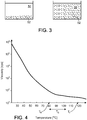
- Figure 4 shows a schematic viscosity-temperature graph, adapted from http://www.argueso.com/uploads/Tech_Pub_Rheology.pdf.
- a viscosity-temperature graph contains information that influences the selection of the operating temperature of the inkjet printing system. For example, the timing of freezing and melting is determined based on the information of such a graph.
- the melting temperature T M of the wax is 78 °C, and indicated in the figure as T M .
- ink is jetted at a higher temperature T J , for example, at 110 °C up to 150 °C but typically about 125 °C.
- the jetting temperature is selected based on the viscosity required by the inkjet head and the melting point of the wax. The viscosity is plotted on a logarithmic scale, indicating that large changes in viscosity occur over a comparatively small range of temperature.
- the melting point T M for inks having low melting point waxes is in the range of 40-50 °C while waxes with high melting point have T M over 80-90 °C.
- Various waxes can be mixed to achieve a composite wax having a selected melting point.
- a typical melting point of the wax can be 40 °C -80 °C depending on the type of wax used so the typical freezing starts just below the melting point.
- Viscosity of the ink to be jetted is typically 10- 20 mPa*s (10-20 cps) but can be higher or lower, for example, between 5-30 mPa*s (5-30 cps). It is important to prepare the ink to be jetted to a viscosity suitable for the printhead.
- the high (or low) viscosity of the ink can cause jetting abnormalities that create tails (satellites), and affect the velocity and direction of travel of the drop.
- a state of quiescence within the temperature range T Q in which the wax exists in a mixture state between the solid and liquid phase occurs between T M and T J .
- ink pigment can separate from the wax, but such separation does not occur rapidly.
- the ink in the inkjet head is held in such a quiescent mode to allow the wax to be heated up quickly when the ink is to be jetted.
- the frozen ink must be liquefied. This could be done by turning off the cooling provided by the ink phase change system, which may allow the ink to rise to the ambient temperature and melt, or could be done more aggressively by deliberate heating. Once the ink is melted, it is important to begin the inkjet printing promptly in order to reduce the extent to which the pigment separates from the medium in the liquid ink. Once inkjet printing is underway, the flow of the ink along the inkjet path and the process of jetting the ink from the pressure chamber provide agitation of the ink that reduces the extent of separation.
- the controller 22 can be used to control the timing and profile of the phase change of the ink from solid to liquid as desired.
- the delay that occurs between the time when the phase change from solid to liquid yields a viscosity appropriate for jetting and the moment when the actual jetting begins can be called the "phase change to jetting delay".
- the phase change jetting delay may vary, but typically should be in the range of 2-10 minutes depending upon the type of heating used, preferably between 2-3 minutes.
- the system may be operated in a quiescent mode in which the wax is cooled to just below its melting point, when the system is not being used for a short period of time say a few hours or less.
- the system can be more quickly re-started and the system can heat the wax to a good (e.g., optimum) jetting temperature much more quickly than if the wax were cooled to a temperature much lower than its melting point.
- Ink is jetted at the jetting temperature and is not jetted in the quiescent state.
- the advantage of holding the system in the quiescent mode includes the use of less power compared to the power required to cool the wax to a temperature much lower than its melting point.
- another advantage is the increased ability to keep the ceramic pigments in dispersion compared to when the ceramic wax is held above its melting point
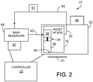
- the inkjet printing system and inkjet devices that make up the printing system together define an ink pathway 31, shown schematically.
- One part 30 of the ink path proceeds through elements of an inkjet head assembly 32 that includes one or more inkjet heads 18.
- Each of the inkjet heads can include a number (e.g., a very large number) of inkjets 34.
- Each inkjet can include a pressurized inkjet chamber 36 that receives a supply of ink from the reservoir 38 and, when pressurized, jets a small volume of the ink through an orifice 40 towards the substrate 41.
- Ink for jetting can be supplied to the reservoir 38 through a supply line 42 from a larger source or reservoir 44 of ink 46.
- the reservoir 44 in turn, can be kept loaded by the operator of the ink jet system in a variety of ways.
- the ink pathway may also include one or more lines 45 that return excess, surplus, or wasted ink from the reservoir 38, from areas around the orifice, and the from pressurized chambers, for example, to the ink reservoir 44 for reuse.
- the ink pathway can be thought of as running from the reservoir 44 through the pressurized chambers and back to the reservoir 38.
- the ink phase change system of figure 1 can comprise a number of components 47, 49, 51 shown schematically figure 2 as thermally coupled to respective elements along the inkjet pathway 31.
- reservoirs 38 and inkjet head assemblies may be used, of course.
- the dense pigment will tend very quickly to settle within each part of the inkjet path, as suggested in the left side of figure 3 . Later, if jetting were to be started again, there would be no assurance that the dense particles could be caused to be dispersed evenly within the liquid ink. Unless the pigments are evenly dispersed within the liquid ink, the quality of the pattern that is then laid down during subsequent jetting will suffer. Agitating the ink and recirculating the ink during the periods when jetting is not going on may help to keep the pigment dispersed within the medium. Other techniques could also be used.
- the medium of the ink is a phase-changing material, such as wax
- the medium of the ink is a phase-changing material, such as wax
- the particles 52 separate (e.g., by settling) within the liquid.
- the process of using a pigmented phase change ink for printing can begin when the inkjet printing system is in a quiescent state 60 in which the ink is in a solid phase, the pigment is satisfactorily distributed and entrained within the solid phase, and the conditions are not changing in a way that would cause the phase to change back to liquid.
- a solid-to-liquid-phase-change period 64 is caused to occur.
- the ink has just reached the condition in which it can be effectively jetted.
- phase-change-to-jetting delay 66 there is a phase-change-to-jetting delay 66.
- delay 66 should be short enough to reduce the tendency of the pigment to become separated in the liquid ink, and can be as short as possible in some examples.
- a phase-change-delay 70 begins.
- the length of delay 70 should be short enough to reduce the amount of separation to an acceptable level.
- the quiescent state 60 is reached again.
- the length of delay 70 may be shorter than 300 seconds.
- wax-based glazing materials could contain particles to be used for providing glazes on ceramic substrates, for example.
- the particles could be large glass particles, frit particles, or other glaze particulates.
- Such glazing materials could be jetted onto the ceramic substrate before inkjet printing a pattern and often after printing the pattern.
- Such wax-based glazing materials could be cooled and/or heated at appropriate times during the processing of the ceramic substrates, in much the same way as we have described for the inks.
- the wax-based glazing materials can be jetted to form a continuous layer of glaze or could be jetted selectively in a pattern, which can be a large-scale pattern, or a small-scale pattern that achieves a textured appearance on the substrate.
Description
- This description relates to phase-change ink jetting.
- In some kinds of ink jetting systems, the ink (sometimes called a hot melt ink) includes a dye or pigment held in a medium such as wax that is in a solid phase at room temperature. For jetting, the ink is heated to change the wax to a liquid state that can be jetted through a jetting orifice onto a substrate from an inkjet pressure chamber. Such inks can be shipped from the vendor to the place where the jetting is done in the form of a solid, easy to handle puck. For use, the puck is loaded into a chamber where it is heated to melt the wax, and the liquid ink can then be delivered along an ink pathway to the orifice and onto the substrate. Heaters (and related thermocouples for control purposes) can be provided at places along the ink pathway to keep the ink melted while jetting is going on. If the jetting system is turned off, and returns to room temperature, the ink solidifies. Later, the heaters can be used to melt the ink to permit jetting again.
- Some known hot melt inks were jetted at 125°C and at a viscosity of 20 mPa*s (20 centipoise (cps)) and contained pigments. Such hot melt inks were solid at room temperature and were heated or cooled rapidly to transition back and forth between solid and liquid phases to prevent separation of the pigments from the medium. Many of the pigments were typically made from dyes reacted with polymers and then ground up into particles so that their density was low compared to titanium dioxide, for example. Carbon black, which is not a dye, has also been used as such a pigment.
-
US 2002/144627 A1 describes ink suitable for application to a heat resistant substrate and firing to fuse the ink to the substrate, the ink being in a form for ink jet printing. -
US 5 992 991 A describes an ink jet recording device capable of controlling temperature of melted ink. - It is known to force cool transparencies after printing with hot melt ink to keep the ink from crystallizing, which would impair its transparent qualities.
- The present invention is defined by
independent claims 1 and 14. The dependent claims depict other embodiments of the invention. - The examples that we describe later exhibit one or more of the following aspects and features.
- In general, in an aspect, ink is jetted onto a substrate, the ink includes (a) a pigment and (b) a wax, and the jetted ink on the substrate is heated to fire the pigment on the substrate.
- Implementations may include one or more of the following features. The pigment includes dense particles. The pigment includes an earth pigment. The substrate includes a material that can be fired in a kiln. The substrate includes a ceramic or a glass. The wax is in a solid phase at room temperature. The ink is jetted in a pattern including at least one of an image, text, or graphic. The jetted ink is heated to a temperature of at least 120°C. The wax is liquid during the jetting. After the jetting and before the pigment has substantially separated from the wax within the ink, the wax is caused to change from a liquid state to a solid state. Before the jetting, the wax is caused to change from a solid state to a liquid state.
- In general, in an aspect, an inkjet printing system includes an inkjet head including an ink pathway from a source of ink to orifices from which ink is to be jetted onto a substrate. A thermal structure is thermally coupled to the ink pathway in at least some places along the pathway to add or remove thermal energy to or from the ink pathway to cause phase changes of the ink between a liquid phase and a solid phase. A supply of ink includes dense pigment and a medium that have a solid phase at room temperature and a liquid phase at a higher-than-room temperature.
- Implementations may include one or more of the following features. The supply of ink is held in a reservoir coupled to the head. A controller causes the thermal structure to change the phase of the ink from a liquid phase to a solid phase after the jetting of ink onto the substrate. The thermal structure is capable of cooling elements along the ink pathway to cause the ink to change phase from a liquid phase to a solid phase.
- In general, in an aspect, an ink jet printing system includes an ink pathway between a source of ink and orifices from which ink is to be jetted onto a substrate. A cooling structure is thermally coupled to the ink pathway in at least some places along the pathway to cool ink within the pathway to cause the ink to change from a liquid phase to a solid phase after jetting.
- Implementations may include one or more of the following features. A controller triggers the cooling structure to cause the phase change to occur no later than 300 seconds after the jetting. A controller triggers the cooling structure to cause the phase change to occur quickly enough to prevent substantial settling of pigment within the ink.
- In general, in an aspect, in a set of phase changing jetting inks, each of the phase changing jetting inks includes (a) (i) particles that have a density of at least 4.5 g/cm3 and that form a fired non-white color when heated to around 1200 °C on a substrate on which the ink is to be jetted, the fired colors of the respective jetting inks being different or (ii) particles that have a density of at least 6 g/cm3 and that form a fired white color when heated on a substrate on which the ink is to be jetted, and (b) a medium that changes phase from liquid to solid at a temperature between 40°C - 120°C. The inks are jettable to form a multicolor fired design on the substrate when fired. Phase changing jetting inks that form a fired white color (other than from titanium dioxide) when heated to around 1200 °C on a substrate include particles that have a density of at least 7 g/cm3.
- Implementations may include one or more of the following features. The particles include earth pigments. The particles include at least one of spinel iron-chromium-zinc, soluble or insoluble gold complexes/salts, tin-chromium oxide, zirconium praseodymium yellow, yellow titanates, spinel iron-chrome-zinc-alumina, cobalt-alumina or cobalt-silica and cobalt-chromium-alumina, spinel iron-chromium-cobalt. The medium includes wax.
- In general, in an aspect, in a pattern of one or more inks that is jetted onto a surface of a ceramic or glass substrate, each of the inks includes (a) (i) particles that have a density of at least 4.5 g/cm3 and that will form a corresponding non-white color when fired or (ii) particles that have a density of at least 6 g/cm3 and that will form a corresponding white color when fired, and (b) a wax medium that changes phase from liquid to solid at a temperature in the range of 40°C - 120°C. The substrate is heated to fire the pattern on the surface of the substrate.
- Implementations may include one or more of the following features. The jetting includes jetting a multi-color pattern of inks. The particles include earth pigments. The particles include at least one of: spinel iron-chromium-zinc, soluble or insoluble gold complexes/salts, tin-chromium oxide, zirconium praseodymium yellow, yellow titanates spinel iron-chrome-zinc-alumina, cobalt-alumina or cobalt-silica and cobalt-chromium-alumina, spinel iron-chromium-cobalt and/or other such ceramic pigments. Depending upon the design of the tile; a variety of ceramic pigments may be required (we use the phrase ceramic pigments to refer to pigments that are used on ceramic substrates). An inkjet head is a unit that includes an array of inkjets and associated pressure chambers. Each color of the multi-color pattern of inks can be associated with a corresponding inkjet head. The ceramic pigments typically include particles that will form a brown color on the substrate and in some cases one or more of: red, pink, yellow, beige, blue, greenish blue and black. White can also be used if the base color of the tile is not white. Heating the substrate to fire the pattern includes heating the substrate in a kiln. Before the jetting, the wax medium is heated to change it from a solid phase to a liquid phase. After the jetting, the wax medium is cooled to change it from a liquid phase to a solid phase. The same pattern is jetted onto a series of substrates, then the medium is forced to change from a liquid state to a solid state within an inkjet system that is doing the jetting. Later, the medium is caused to change from a solid state to a liquid state. Then, a different pattern is jetted onto a series of substrates.
- In general, in an aspect, an ink that is in a liquid phase and that is jetted from an inkjet onto a substrate includes particles that can be fired on the substrate and have a density of at least 4.5 g/cm3. After the ink has been jetted, ink in the inkjet is caused to change to a solid phase to reduce settling of the particles in the liquid phase. Later, the ink in the inkjet is caused to change to the liquid phase again, and ink is jetted from the inkjet onto another substrate.
- In general, in an aspect, a wax-based ink in an inkjet printing system is forced to change from a liquid state to a solid state within no more than a predetermined period after the inkjet printing system has jetted ink onto a substrate.
- Implementations may include one or more of the following features. The predetermined period is less than 300 seconds.
- These and other aspects, features, and implementations, and combinations of them, can be expressed as methods, compositions of matter, apparatus, systems, program products, means and steps for performing functions, methods of doing business, and in other ways.
- Other aspects and features will become apparent from the following description and from the claims.
-
-
Figure 1 is a schematic view of a printing line. -
Figure 2 is a schematic view of ink flow. -
Figure 3 is a schematic view of ink in two phases. -
Figure 4 is a temperature viscosity graph. -
Figure 5 is a flow diagram. - In at least some of the examples that we describe below, ink that is to be jetted onto a substrate includes a pigment and a medium (such as wax) that is caused to change phases between solid and liquid between times when the ink is not being jetted and times when it is being jetted, respectively. In some implementations, the pigment includes dense particles. By freezing the medium (changing it to the solid phase) at times or during periods when jetting is not going on, the dense particles can be entrained in the medium which helps to slow or stop the tendency of those particles to sink and separate from the medium, and reduces the opportunity for these particles to separate within the medium, which would make the jetting of the ink (including the pigment) difficult during the next jetting session and could cause clogging in the printhead.
- In some cases that we describe below, the pigment includes particles that can be fired, for example, in a kiln. We take advantage of that feature, in some examples, by using such inks to lay down decorative patterns on a substrate that can tolerate firing in a kiln. The substrate could be, for example, a glass or ceramic tile, either in the unfired green state or in a fired state. After the pattern is laid down, the substrate with the pattern is fired. The high heat required for firing drives off the medium and fires the pattern permanently on the surface of the substrate. Because the patterns that are to be laid down on the substrate can be changed frequently, for example, as frequently as for each individual unit of the substrate (that is, in a "lot of one" mode), such a printing and firing sequence can save money and time.
- In our discussion, we use the term jetting broadly to include, for example, any forcing of ink from an orifice and onto a substrate, including drop on demand systems. We mean to include, but not be limited to, a wide variety of ink jetting systems and the inkjet heads that are part of them, including those that now exist and may be developed in the future.
- We use the term substrate also broadly to include, for example, any workpiece onto which ink is jetted. Sometimes the work piece is a glass or ceramic item on which a pattern or image or text is to be laid down and fired. But the work piece could be any kind of material in any form, phase, shape, size, weight, density, or configuration, for example, that can accept the laying down of an ink jetted pattern.
- When we refer to a pigment, we intend to include, broadly, any kind of material in an ink that provides a color or colors or other characteristic or quality on a substrate on which ink is jetted. Often, the pigment will be comprised of what might be called particles, but any kind of pigment that is subject to separation, or sedimentation, or settling within a matrix of the ink of which the pigment is part, would be included in the term, among other things. In some cases, a pigment is referred to as an earth pigment, by which we mean to include pigment derived from naturally occurring substances, such as rock and other hard materials. As we discussed below, a pigment can provide color to an ink, but a pigment in our way of using the term could also include particles that provide other characteristics, such as a glaze or frit (in a continuous layer, a large-scale pattern or a small-scale pattern or texture) when applied to a substrate and fired, for example.
- We use the term ink in a broad sense to include any material that includes a medium and a pigment and that in some phase or state can be jetted from an inkjet.
- By the term color, we mean any color in the spectrum, and black, white, and gray-scale.
- We use the term medium in a very broad sense to include any material in which the particles or other elements that make up a pigment are entrained or mixed or held. Often, when we refer to medium we mean a material that is, at least at some times and in some circumstances, in a form in which the elements that make up the pigment may separate and not be evenly distributed or dispersed within the medium. At other times or in other circumstances, the elements that make up the pigment are evenly distributed or dispersed within the medium.
- When we use the term wax, we include broadly any kind of traditional or non-traditional wax and any artificial or natural wax and also any other material (whether or not called a wax) that undergoes a reversible phase change from solid to liquid at a temperature that is in the range of, for example, 40°C - 120°C. Typical waxes melt between 40 °C - 80 °C. Materials that undergo phase changes at other temperatures and in other temperature ranges are also included in our use of the word wax. In the liquid phase, the wax can carry particles of a pigment and be jetted with the pigment onto a substrate. In the solid phase, the wax restrains the settling of particles that are entrained in the wax. When we use the term wax we include materials that comprise a single wax or any mixture of waxes in any proportions.
- When we refer to a separation of materials (for example a separation of dense particles from a medium in which they are entrained), we mean to include, for example, any settling, separation, dissociation, diffusion, or other process by which the uniformity of distribution of one material in another is reduced. For example, dense particles of a pigment may separate within a liquid medium, but not within a solid medium.
- We use the term fire broadly to include, for example, applying high heat to cause particles to melt and form a mass that, when cooled, forms a hard material such as permanently on a substrate. In some examples, firing includes the high heating that occurs in a kiln. High heat can include heating to a temperature that is in the range of 550 -1350 °C . For example, kilns for overglaze or china painting can operate at temperatures between 550 °C and 800 °C, or between 586 C to 763 °C, kilns for glass firing can operate at temperatures between 750 °C to 950 °C , for example between 757 °C to 915 °C, kilns for low fire ceramics can operate at temperature between 950 °C to 1200 °C, for example between 981 °C to 1154 °C, kilns for mid fire ceramics can operate between 1100 °C to 1300 °C , for example between 1112 °C to 1257 °C, and high fire ceramics can operate at temperature between 1200 °C to 1350 °C , for example between 1211 °C to 1305 °C.. In some examples, the mass is formed from something that might not be called particles and the something from which the mass is formed may not require heating as hot as the temperature range just mentioned.
- In the term ink pathway, we broadly include, for example, any pathway along which liquid ink flows from a source or reservoir or supply of ink to a place where the ink is jetted or dispensed or used, among other things. The pathway might also include a portion along which excess ink is returned to a source or reservoir. We tend to use the words source, reservoir and supply interchangeably with respect to ink.
- We use the term freeze to include, for example, cooling a material so that it undergoes a phase change from liquid to solid. The cooling could occur naturally as heat is dissipated into a cooler ambient, or could be caused deliberately by cooling equipment. Before the ink or the medium is fully frozen, there exists an intermediate state of quiescence in a temperature range between the melting point of the medium and the jetting temperature of the ink in which the medium exists in a mixture state between the solid phase and the liquid phase. In this quiescent state, ink pigments can separate from the medium, but such separation does not occur rapidly.
- In using the term orifice, we broadly include, for example, any opening at the end of an ink pathway through which ink is jetted towards a substrate.
- When we use the term thermally coupled, we mean to include broadly any arrangement to, for example, permit heat to flow readily.
- We use the term particles broadly to include, any kind of, for example, elements of a material that have a size in the range of hundreds of nanometers (nm). A typical graphics pigment has particles that are about 100 nm but in an ink the graphics pigments can have sizes that range from well under 100nm to over 1 µm (1 micron). Ceramic pigments, on average, are larger. Examples of such ceramic pigments include finely ground ceramic pigments having small or sub-micrometer (sub-micron) particles. The ground up pigments often have a distribution of particle sizes, so even though many pigment particles are sub-micrometer (sub-micron), in some cases an absolute filter is used to ensure that particles larger than, for example, 5 µm (5 micron) would not pass through the filter to enter a printhead. A system capable of jetting larger ceramic pigments, and keeping these pigments dispersed would be very desirable for ceramic tile decoration. Nonetheless, in addition to the weight of ceramic pigments being approximately twice that of graphics pigments, a given volume of ceramic ink contains approximately twice the amount of pigments compared to graphics pigment (we use the phrase ceramic ink to refer to ink that contains ceramic pigments that are used on ceramic substrates). Thus, for a given volume of ceramic ink, there is twice the amount of ceramic pigments compared to the amount of graphics pigment in graphics ink, and the ceramic pigments weigh twice as much as graphic pigments. As a result, the density of ceramic ink is approximately four times the density of graphic ink.
- By a dense pigment, we mean broadly any pigment, for example, the particles of which have a density of at least 4.5 g/cm3 and form a fired non-white color when heated on a substrate, or the particles of which have a density of at least 6 g/ cm3 and form a fired white color when heated on a substrate.
- By room temperature, we mean a temperature in the range of 18.3 °C to 23.9°C (65° to 75°F) or ambient temperature.
- When a material undergoes a phase change, for example, from liquid to solid or solid to liquid, a delay occurs until the change has been completed. We sometimes refer to this delay as a phase change delay. How short the phase change delay ought to be will depend, of course, on the constituents of the ink, and, in particular, on how fast the separation of the pigment from the medium happens, and on how much separation can occur without degrading printing quality unacceptably. An intermediate state of quiescence exists in a temperature range between the melting point of the medium and the jetting temperature of the ink in which the medium exists in a mixture state between the solid phase and the liquid phase. In this quiescent state, the medium is not frozen and ink pigment can separate from the medium, but such separation does not occur rapidly. The ink in the inkjet head is held in such a quiescent mode to allow the medium to be heated up quickly when the ink is to be jetted
- As shown in
figure 1 , in some examples of the concepts that we are describing here, formed units of apowder mixture 8 that include clay, water, and earth materials are shown asdiscrete precursor workpieces 10. The workpieces, which will eventually become part of finished ceramic tiles, enter a processing line 12 (for example, they may be carried along on a conveyor). These precursor units ofpowder mixture 8 are processed using apress 11 that exerts a pressure of, for example, about 2.8*106 Pascal 400 pounds per square inches on each of theprecursor workpieces 10, to yield wetgreen tiles 13, which have a 5-10% water content, for example. The wetgreen tiles 13 may be squares having sides of 700 mm. Along theprocessing line 12, afirst kiln 17 operating at 200 °C receives the wetgreen tiles 13 and dries them intoceramic tiles 19. Theceramic tiles 19 may be sent to an inventory 23 or sent further along theprocessing line 12 for decoration. - Ceramic tile decoration, in this example, includes one or more steps of glazing, printing, and using brushes to create grooves or texture in the
tiles 19. Further along theprocessing line 12, at a frit glaze station 25, frit, which are small glass particles, are flood coated (deposited) onceramic tiles 19. The frit particles are fired into a frit glaze in asecond kiln 20. The frit glaze seals theceramic tiles 19 and creates a glossy finish on the tiles to formsubstrate units 22 which can accept printing of a pattern. One or more of analog and digital printing or a combination of them may be used on thesubstrate units 22. In analog printing, a silicone drum deposits ceramic pigments on thesubstrate units 22. A rotary screen can also be used in analog printing. - Digital printing can use an ink
jet printing system 14 that lays down a two-dimensional pattern 15 on an exposedupper surface 16 of each of thesubstrate units 22. Thepattern 15 is laid down by jetting ink from orifices of one or more inkjets of one or more inkjet heads 18 that are part of the ink jet printing system, in accordance with a desired pattern. Among a wide variety of other possibilities, the pattern that is laid down can include one or more colors and represent decorations, text, images, or graphics, among other things. - After printing,
substrate units 22 may go through a second glazing station 27 where additional frit may be flood coated or deposited on thesubstrate units 22, in some cases selectively. Such a glaze adds depth to the color printed on thesubstrate units 22 earlier in the processing line. In addition, various types of brushes can be optionally used to create textures and designs on thesubstrate units 22. - In some examples, the ink that is jetted to form the pattern is formulated as a combination of a wax and a dense pigment that can be fired. Of course, a wide variety of other components can be included in the formulation of the ink for a variety of purposes. In the case of ceramic pigments, the wax (or a mixture of waxes) comprises the major component of the ceramic ink.
- For example, a ceramic ink may contain ceramic pigments in the range of 3-15% by volume of the finished ink (dependent, for example, on the type of ceramic, and the inkjet system capability) and a dispersing agent that binds onto the pigments (to keep the pigments separated when the wax is molten). In some cases, a resin may be used as the dispersing agent. There are, however, cases in which the dispersing agent will have no value in fixing the wax on certain tiles prior to firing in the kiln. Additional components may be used in formulating the ink. Anti-oxidants, which are used in some graphics wax formulations, may not be needed in a ceramic ink formulation because the wax used for ceramic pigments will be burned off during the firing process. Suitable inks may be available as formulated by commercial ink vendors including Tektronix/ Xerox in Beaverton/Wilsonville Oregon, Sunjet/ Sun Chemical in Bath, U.K., and Markem Imaje in Keene NH.
- Ceramic ink formulation may not include some of the components used in graphics wax formulations. Graphic wax formulations include a colorant; either dyes or pigments; a wax; or a mixture of waxes depending on the application; a dispersing agent that binds onto the pigment and keeps the pigment from clumping, separating from the wax, or settling; an anti-oxidizing agent that keep the wax from aging (for example, from turning yellow); and an adhering resin that allows the wax to stick to the intended substrate.
- A ceramic wax may have other properties/requirements and may not include adhering agents and anti-oxidizing agents. In a graphics wax formulation; the graphics pigments (generally cyan, yellow, magenta and black) make up 2-5% of the formulation by volume. In a ceramics ink; the ceramic pigments may be in the range of 4 % to over 10% by volume except ceramic white which could an even higher volume percentage in the ceramic wax formulation. The dispersing agent may be mixed with the ground up pigment before the mixture is combined with the carrier (we sometimes use the word carrier interchangeably with medium). Sometimes a surfactant is added so that the ink better wets the substrate.
- In examples in which the substrate is ceramic, the pigments are typically dense (heavy). Most ceramic pigments are 2 to 4 times denser than what are known as graphics pigments and are very much denser than the dyes in dye-based inks, which have almost the same density as water. White, titanium dioxide, is the densest graphics pigment at about 4.5 g/cm3. Black (generally carbon black) is less dense, at about 2 g/cm3. Most other graphics pigments, primarily cyan, yellow and magenta, have a density of 2 g/cm3 or less. White ceramic pigment is 3-4 times denser than graphics pigments and at least 40% denser than titanium dioxide (a graphics white pigment that is not used as a ceramic pigment). Ceramic pigments typically have densities in the range of 4.5 to 6 g/cm3 although in some cases the densities could be lower or higher than that range. Examples of earth pigments used as ceramic pigments are the following: yellow: zirconium praseodymium yellow; beige: beige spinel iron-chromium-zinc-alumina; brown (most commonly used): spinel iron-chromium-zinc brown; blue can be cobalt-alumina or cobalt-silica; red: soluble or insoluble gold.
- By contrast, certain graphics pigments (primarily cyan, yellow, magenta and carbon black) have densities of approximately 2 to 2.5 g/cm3 or less, and graphics white in the form of titanium dioxide (TiO2) has a density of about 4.5 g/cm3.
- In some production lines, the workpieces can be moved past the inkjet printing system in a row, as suggested in
figure 1 , or in any of a variety of other ways. Among others, a set of workpieces that are arranged side-by-side can all be delivered past the inkjet printing system at one time followed by another set and so on. A wide variety of other arrangements are possible. - At some point after the patterns are laid down, the workpieces proceed along the processing line into a
third kiln 21, where the workpieces are heated to a high temperature, that is, they are fired. - The firing of the workpieces in the kiln causes the wax to evaporate or burn off and then the pigment to be fired into a permanent pattern that lies on, is attached to, or becomes an integral part of the top surface of the workpiece. The
third kiln 21 operates at temperatures above 1000 °C, typically above 1200 °C. Thethird kiln 21 may have a length that is at least 50 m, or it may also be over 100 m. Additional processing steps can be included after thekiln 21 for various purposes, such as an optional polishing, and, following those steps, the fired workpieces can be removed from the line and put into commerce. - The
processing line 12 may also include an electronic or programmed controller used to control the progress of the workpieces along the processing line, the operation of the printing system, the operation of the kiln, and potentially a wide variety of other aspects of the operation of the processing line. - The
inkjet printing system 14 may include an inkphase changing system 24 that includes elements that are designed to promote phase changes between solid and liquid in the ink that is used in the inkjet printing system. In some cases, the inkphase changing system 24 is designed only to promote phase changes in one direction, for example, from liquid to solid, by cooling one or more elements along the ink pathway within the inkjet printing system. These elements can include, for example, a main reservoir of ink, conduits that carry ink from the main reservoir to an array of inkjet heads, a local reservoir associated with the inkjet heads, or with individual inkjet heads, with conduits that carry ink from the local reservoir to the inkjet head, and with conduits and other elements of a recirculation system that carry unused or waste ink in a return path from the inkjet head to the local reservoir or from the local reservoir to the main reservoir. Within a given inkjet head, the cooling elements may be associated with the inkjet pressure chamber, the orifice, and any of the other elements that comprise the inkjet head. - An inkjet head typically contains 3-20 cm3 of wax and the main reservoir contains more wax than the inkjet head. The volume of wax influences the time needed to achieve freezing or melting. The ink freezing temperature varies depending upon the melting point of the ink. If the melting point of the ink is between 70-80 °C, the ink can begin freezing (solidifying) when the heater is turned off, as soon as the ink gets below its melting point. As the viscosity increases, due to the solidification, the pigments become more stable until it is fully frozen in place. If no additional freezing aid is applied; the ink in the inkjet head will generally freeze within four to ten minutes depending upon the volume of ink in the inkjet head.
- Freezing of the wax in the inkjet head needs to controlled to reduce damage to the inkjet head that can occur if freezing of the wax occurs too quickly. For example, the ink may crystallize when frozen too quickly, and the ink also shrinks as it crystallizes, giving rise to cracks and voids in the block of crystallized ink. The crystallized ink block also may pull off and damage conformal coatings on the inkjet head, such as parylene coatings.
- The cooling done by the ink phase changing system may be done using a cooling fluid passed through conduit, by air cooling, or by any other approach that will produce a sufficiently short ink phase change delay, or by any combination of them. Using a muffin fan to blow ambient air onto the inkjet head can decrease the freezing time of the wax from ten minutes to three minutes. By using a freezing agent, such as Freon™, the wax can be frozen in approximately one minute which may not cause damage to the head. Often, the ink phase change system, or parts of it, will need to be thermally coupled to corresponding elements of the inkjet printing system, for example, by being incorporated into them or attached to them.
- The
controller 22 can be configured to control the ink phase change system in coordination with control of the inkjet printing system. For example, suppose that the inkjet printing system is printing a pattern on a succession of substrate units and the run is nearing completion. Suppose that theproduction line 12 will be stopped then for awhile to permit changes in the workpieces, the pattern, or combinations of them. When the final workpiece of the current run has passed through the inkjet printing system, and the system is not required to use the inkjet printing system to decorate more workpieces, the controller could trigger operation of the ink phase change system to promptly cool the ink in the inkjet printing system to force a phase change from liquid to solid when the system is no longer in use and is to be shut down. By sizing the cooling capacity of the phase change system appropriately, triggering the operation of the ink phase change system will cause the phase change to occur with a phase change delay that is short enough to prevent separation of the pigment from the medium to an extent that would degrade the printing unacceptably. In some cases, the phase change can be effected at different times and with different speeds in different parts of the inkjet printing system, to achieve the desired result. In some cases, a particular profile of cooling could be obtained over a short period of time and in different parts of the inkjet printing system, again to achieve a desired result. - The speed and staging of the phase change from liquid to solid can be designed empirically based on the design of the inkjet printing system and the formulation of the ink being used.
- In some cases, the forced cooling might be achieved by a freeze jet, for example, by blowing cold air or Freon on the inkjet head. As the wax cools and before it freezes, the wax gets more viscous, and the higher viscosity of the wax slows the rate of pigment separation.
- Besides the freezing of the wax based inks, the higher viscosity, 20 mPa*s (20 cps), during jetting would slow the settling of the pigments. The higher the viscosity, the longer the time taken for particles to settle. It is beneficial to have ink viscosity of 20 mPa*s (20 cps) than for example 1-2 mPa*s (1 -2 cps), when jetting. As the ink is cooled before it freezes, the viscosity continues to rise, further slowing the settling of particles, (see
figure 4 for change in viscosity as a function of temperature). - An off-head system (OHS), if used to deliver ink from a reservoir to the head, in some examples may not need a quick freeze, because it typically will have an agitation system (used only when the wax is hot). Reservoirs (not heads) typically have an agitation (mixer) in the reservoirs, which are often a meter away from the heads and fed by umbilicals. These OHS reservoirs hold a larger amount of wax-based ink (for example, between 30 cm3 to many hundreds of cm3 and may even hold kilograms of wax-we sometimes use the word wax to refer to the ink that uses a wax medium) than the inkjet head. In some examples, when agitation is not done or for other reasons, the reservoir may need to be force cooled also. Ink in a heated umbilical freezes very quickly once heat (for example a heated umbilical threaded into the ink tubing) is turned off. This happens in under a minute from over 40-80°C to full freeze without any aid.
- One can be more aggressive freezing this ink by using cold plates or air conditioners to aid in capturing the heavy ceramic pigments in place more rapidly. In addition, the ink in the OHS reservoir does not need to be kept at the jetting temperature, but only at the ink's melting point which is sufficient for pumping to the head. Therefore, freezing of the ink in the OHS reservoir can be more rapid and aggressive. Moreover, the OHS reservoir typically does not contain conformal coatings, and can thus withstand more rapid and aggressive cooling (and the formation of splits and gaps) compared to the inkjet head.
- Although we have discussed an ink
phase change system 24 that changes the phase of the ink from liquid to solid, of course, the ink phase change system could be one that changes the phase from solid to liquid, or one that is capable of doing both jobs in any sequence and with any desired speed in any selected parts or all of the inkjet printing system. A purge may be part of the startup routine for the inkjet head to force ink out of the orifices and collect it as waste ink at a maintenance station (not shown). -
Figure 4 shows a schematic viscosity-temperature graph, adapted from http://www.argueso.com/uploads/Tech_Pub_Rheology.pdf. Such a viscosity-temperature graph contains information that influences the selection of the operating temperature of the inkjet printing system. For example, the timing of freezing and melting is determined based on the information of such a graph. - In the example illustrated in
figure 4 , the melting temperature TM of the wax is 78 °C, and indicated in the figure as TM. In some examples, ink is jetted at a higher temperature TJ, for example, at 110 °C up to 150 °C but typically about 125 °C. The jetting temperature is selected based on the viscosity required by the inkjet head and the melting point of the wax. The viscosity is plotted on a logarithmic scale, indicating that large changes in viscosity occur over a comparatively small range of temperature. - The melting point TM for inks having low melting point waxes is in the range of 40-50 °C while waxes with high melting point have TM over 80-90 °C. Various waxes can be mixed to achieve a composite wax having a selected melting point. A typical melting point of the wax can be 40 °C -80 °C depending on the type of wax used so the typical freezing starts just below the melting point.
- Viscosity of the ink to be jetted is typically 10- 20 mPa*s (10-20 cps) but can be higher or lower, for example, between 5-30 mPa*s (5-30 cps). It is important to prepare the ink to be jetted to a viscosity suitable for the printhead. If the viscosity of the jetted ink is much higher than 30 mPa*s (30 cps) (e.g., 20 mPa*s (50 cps)) or much lower than 5 mPa*s (5 cps) (e.g., 2 mPa*s (2 cps)), the high (or low) viscosity of the ink can cause jetting abnormalities that create tails (satellites), and affect the velocity and direction of travel of the drop.
- In some examples, a state of quiescence within the temperature range TQ in which the wax exists in a mixture state between the solid and liquid phase occurs between TM and TJ. In this quiescent state, ink pigment can separate from the wax, but such separation does not occur rapidly. The ink in the inkjet head is held in such a quiescent mode to allow the wax to be heated up quickly when the ink is to be jetted.
- Continuing our example above, while the ink is in the frozen (solid) state in the inkjet printing system, and before the next run of inkjet printing occurs, the frozen ink must be liquefied. This could be done by turning off the cooling provided by the ink phase change system, which may allow the ink to rise to the ambient temperature and melt, or could be done more aggressively by deliberate heating. Once the ink is melted, it is important to begin the inkjet printing promptly in order to reduce the extent to which the pigment separates from the medium in the liquid ink. Once inkjet printing is underway, the flow of the ink along the inkjet path and the process of jetting the ink from the pressure chamber provide agitation of the ink that reduces the extent of separation. Agitation devices and techniques can also be used in reservoirs to reduce the separation. In any case, the
controller 22 can be used to control the timing and profile of the phase change of the ink from solid to liquid as desired. The delay that occurs between the time when the phase change from solid to liquid yields a viscosity appropriate for jetting and the moment when the actual jetting begins can be called the "phase change to jetting delay". The phase change jetting delay may vary, but typically should be in the range of 2-10 minutes depending upon the type of heating used, preferably between 2-3 minutes. - The system may be operated in a quiescent mode in which the wax is cooled to just below its melting point, when the system is not being used for a short period of time say a few hours or less. In this way, the system can be more quickly re-started and the system can heat the wax to a good (e.g., optimum) jetting temperature much more quickly than if the wax were cooled to a temperature much lower than its melting point. Ink is jetted at the jetting temperature and is not jetted in the quiescent state. The advantage of holding the system in the quiescent mode includes the use of less power compared to the power required to cool the wax to a temperature much lower than its melting point. In addition, another advantage is the increased ability to keep the ceramic pigments in dispersion compared to when the ceramic wax is held above its melting point
- As shown in
figure 2 , in some implementations, the inkjet printing system and inkjet devices that make up the printing system together define anink pathway 31, shown schematically. Onepart 30 of the ink path proceeds through elements of aninkjet head assembly 32 that includes one or more inkjet heads 18. Each of the inkjet heads can include a number (e.g., a very large number) ofinkjets 34. Each inkjet can include apressurized inkjet chamber 36 that receives a supply of ink from thereservoir 38 and, when pressurized, jets a small volume of the ink through anorifice 40 towards thesubstrate 41. Ink for jetting can be supplied to thereservoir 38 through asupply line 42 from a larger source orreservoir 44 of ink 46. Thereservoir 44, in turn, can be kept loaded by the operator of the ink jet system in a variety of ways. - The ink pathway may also include one or
more lines 45 that return excess, surplus, or wasted ink from thereservoir 38, from areas around the orifice, and the from pressurized chambers, for example, to theink reservoir 44 for reuse. The ink pathway can be thought of as running from thereservoir 44 through the pressurized chambers and back to thereservoir 38. - The ink phase change system of
figure 1 can comprise a number ofcomponents figure 2 as thermally coupled to respective elements along theinkjet pathway 31. - When two or more colors or pigments or inks are being used for jetting to lay down a pattern,
multiple reservoirs 38 and inkjet head assemblies may be used, of course. - Referring to
figure 3 , in some examples, when an ink that does not use a phase-changing medium such as wax is not being jetted or actively recirculated along the inkjet path, the dense pigment will tend very quickly to settle within each part of the inkjet path, as suggested in the left side offigure 3 . Later, if jetting were to be started again, there would be no assurance that the dense particles could be caused to be dispersed evenly within the liquid ink. Unless the pigments are evenly dispersed within the liquid ink, the quality of the pattern that is then laid down during subsequent jetting will suffer. Agitating the ink and recirculating the ink during the periods when jetting is not going on may help to keep the pigment dispersed within the medium. Other techniques could also be used. - As shown in
figure 3 , on the right side, if the medium of the ink is a phase-changing material, such as wax, it is possible, by quickly forcing a change of phase from liquid to solid of the wax medium, promptly after jetting has stopped, to entrain the uniformly distributedparticles 50 within a matrix ofwax 52. Later, before jetting is to begin again, by heating the ink, the matrix becomes liquid and the ink can be successfully jetted again. If the jetting begins promptly after the phase change, the quality of the patterns being laid down can be maintained. On the left side offigure 3 , by contrast, as time passes while the ink is liquid, theparticles 52 separate (e.g., by settling) within the liquid. - As shown in
figure 5 , the process of using a pigmented phase change ink for printing can begin when the inkjet printing system is in aquiescent state 60 in which the ink is in a solid phase, the pigment is satisfactorily distributed and entrained within the solid phase, and the conditions are not changing in a way that would cause the phase to change back to liquid. When inkjet printing is to begin, a solid-to-liquid-phase-change period 64 is caused to occur. At the end ofperiod 64, the ink has just reached the condition in which it can be effectively jetted. Subsequently, there is a phase-change-to-jettingdelay 66. Generally, delay 66 should be short enough to reduce the tendency of the pigment to become separated in the liquid ink, and can be as short as possible in some examples. - When the jetting 68 for a given jetting process run comes to an end, a phase-change-
delay 70 begins. As mentioned before, the length ofdelay 70 should be short enough to reduce the amount of separation to an acceptable level. Once thedelay 70 has ended, thequiescent state 60 is reached again. For example, the length ofdelay 70 may be shorter than 300 seconds. - Other implementations are within the scope of the following claims.
- For example, although some of the examples discussed above relate to inks containing earth pigments for use for printing patterns on ceramic substrates. In addition, wax-based glazing materials could contain particles to be used for providing glazes on ceramic substrates, for example. In such examples, the particles could be large glass particles, frit particles, or other glaze particulates. Such glazing materials could be jetted onto the ceramic substrate before inkjet printing a pattern and often after printing the pattern.
- Such wax-based glazing materials could be cooled and/or heated at appropriate times during the processing of the ceramic substrates, in much the same way as we have described for the inks. The wax-based glazing materials can be jetted to form a continuous layer of glaze or could be jetted selectively in a pattern, which can be a large-scale pattern, or a small-scale pattern that achieves a textured appearance on the substrate.
Claims (15)
- A method comprising
jetting onto a substrate (22) ink that includes (a) a pigment and (b) a wax using an inkjet printing system, and
heating the jetted ink on the substrate (22) to fire the pigment on the substrate (22), and characterized by cooling the ink in the inkjet printing system (14) by cooling equipment to effect a phase change of the wax from liquid to solid when the inkjet system (14) is not jetting. - The method of claim 1 in which the substrate (22) comprises a ceramic or a glass.
- The method of claim 1 in which the jetted ink is heated to a temperature of at least 120 °C, and in which the wax is liquid during the jetting.
- The method of claim 1, wherein cooling the ink in the inkjet system (14) occurs after the jetting and before the pigment has substantially separated from the wax within the ink.
- The method of anyone of the preceding claims, wherein cooling the ink in the inkjet printing system (14) comprises passing a cooling fluid through a conduit in the inkjet printing system (14), or
wherein cooling the ink in the inkjet printing system (14) comprises using a fan to blow ambient air onto an inkjet head of the inkjet printing system (14). - The method of anyone of the preceding claims, wherein cooling the ink in the inkjet printing system (14) comprises using a refrigerant.
- The method of anyone of the preceding claims, wherein cooling the ink in the inkjet printing system (14) comprises effecting the phase change of the wax at different times and with different speeds in different parts of the inkjet printing system (14).
- The method of anyone of the preceding claims, wherein cooling the ink in the inkjet printing system (14) comprises cooling the wax to just below its melting point.
- The method of claim 1 comprising
jetting onto a surface a pattern (15) of one or more inks using an inkjet printing system (14), each of the inks comprising (a) particles that have a density of at least 4.5 g/cm3 and that will form a corresponding non-white color when fired or particles that have a density of at least 6 g/cm3 and that will form a corresponding white color when fired, and (b) a wax medium that changes phase from liquid to solid at a temperature in the range of 40 ° C to 120 ° C, and
heating the substrate (22) to fire the pattern (15) on the surface of the substrate (22), and cooling the one or more inks in the inkjet printing system (14) by said cooling equipment to effect a phase change of the wax medium from liquid to solid when the inkjet printing system (14) is not jetting. - The method of claim 9 in which the jetting comprises jetting a multi-color pattern (15) of inks.
- The method of claim 9 in which the particles comprise at least one of: spinel iron-chromium-zinc, soluble or insoluble gold complexes/salts, tin- chromium oxide, zirconium praseodymium yellow, yellow titanates spinel-iron-chrome-zinc-alumina, cobalt-alumina or cobalt-silica and cobalt- chromium-alumina, spinel iron-chromium-cobalt.
- The method of claim 9 comprising jetting the same pattern (15) onto a series of substrates (22), then forcing the medium to change from a liquid state to a solid state within an inkjet system (14) that is doing the jetting, later causing the medium to change from a solid state to a liquid state, and then jetting a different pattern (15) onto a series of substrates (22).
- The method of claim 9 comprising, before the jetting, heating the wax medium to change it from an intermediate state between a solid phase and a liquid phase of the wax to the liquid phase.
- An ink jet printing system comprising
an ink pathway (31) between a source of ink and orifices (40) from which ink is to be jetted onto a substrate (41), characterized by a cooling structure that is thermally coupled to the ink pathway (31) in at least some places along the pathway (31) to cool ink within the pathway (31) to cause the ink to change from a liquid phase to a solid phase after jetting. - The inkjet printing system of claim 14 comprising a controller to trigger the cooling structure to cause the phase change to occur no later than 300 seconds after the jetting.
Applications Claiming Priority (2)
| Application Number | Priority Date | Filing Date | Title |
|---|---|---|---|
| US13/086,077 US8974045B2 (en) | 2011-04-13 | 2011-04-13 | Phase-change ink jetting |
| PCT/US2012/033243 WO2012142236A2 (en) | 2011-04-13 | 2012-04-12 | Phase-change ink jetting |
Publications (3)
| Publication Number | Publication Date |
|---|---|
| EP2697070A2 EP2697070A2 (en) | 2014-02-19 |
| EP2697070A4 EP2697070A4 (en) | 2016-10-12 |
| EP2697070B1 true EP2697070B1 (en) | 2018-08-01 |
Family
ID=47006111
Family Applications (1)
| Application Number | Title | Priority Date | Filing Date |
|---|---|---|---|
| EP12771042.4A Active EP2697070B1 (en) | 2011-04-13 | 2012-04-12 | Phase-change ink jetting |
Country Status (6)
| Country | Link |
|---|---|
| US (1) | US8974045B2 (en) |
| EP (1) | EP2697070B1 (en) |
| JP (1) | JP6005727B2 (en) |
| KR (1) | KR20140037083A (en) |
| CN (1) | CN103596766B (en) |
| WO (1) | WO2012142236A2 (en) |
Families Citing this family (8)
| Publication number | Priority date | Publication date | Assignee | Title |
|---|---|---|---|---|
| US9512328B2 (en) * | 2013-08-22 | 2016-12-06 | Xerox Corporation | Method and system for magnetic particle assisted add-on module on inkjet printer to prevent ink from settling |
| EP3050931A4 (en) * | 2013-09-27 | 2017-04-26 | Seiren Co., Ltd. | Inkjet ink set, method for producing inkjet printed material using same, and inkjet printed material |
| US9527295B1 (en) * | 2015-08-20 | 2016-12-27 | Xerox Corporation | Multipurpose bottle apparatus and bottle loading mechanism and method |
| US9975345B2 (en) | 2015-08-20 | 2018-05-22 | Xerox Corporation | Multipurpose bottle apparatus and bottle loading mechanism and method |
| US20180311892A1 (en) * | 2016-02-26 | 2018-11-01 | Hewlett-Packard Development Company, L.P. | Color printing and three-dimensional (3d) printing |
| CN108587323A (en) * | 2018-04-02 | 2018-09-28 | 刘志哲 | A kind of ceramic ink jet machine oil ink manufacture craft |
| CN108544647A (en) * | 2018-05-29 | 2018-09-18 | 广州精陶机电设备有限公司 | A kind of printing glazing integrated printer |
| CN112721444B (en) * | 2020-12-15 | 2022-06-03 | 佛山市乐彩包装材料有限公司 | High-stability color adjustable printing machine |
Family Cites Families (41)
| Publication number | Priority date | Publication date | Assignee | Title |
|---|---|---|---|---|
| US3444732A (en) | 1967-06-06 | 1969-05-20 | Albert L Robbins | Method and apparatus for determining optimum bonding parameters for thermoplastic material |
| JPS5516388B2 (en) | 1972-09-11 | 1980-05-01 | ||
| JPS55107493A (en) | 1979-02-13 | 1980-08-18 | Nissha Printing Co Ltd | Dyeing method of multicoloured patern on heat resisting base material |
| JPS56113462A (en) * | 1980-02-15 | 1981-09-07 | Nec Corp | Jetting method for ink droplet |
| DE3577980D1 (en) * | 1985-08-06 | 1990-07-05 | Dataproducts Corp | INK-JET DEVICE WITH CHANGE IN DYE CONDITION. |
| US4814786A (en) | 1987-04-28 | 1989-03-21 | Spectra, Inc. | Hot melt ink supply system |
| US4877676A (en) | 1987-05-14 | 1989-10-31 | Spectra, Inc. | Hot melt ink transparency |
| US4801473A (en) | 1987-05-14 | 1989-01-31 | Spectra, Inc. | Method for preparing a hot melt ink transparency |
| US4775232A (en) | 1987-07-10 | 1988-10-04 | Spectra, Inc. | Catadioptric projection lantern |
| US4873134A (en) | 1988-08-10 | 1989-10-10 | Spectra, Inc. | Hot melt ink projection transparency |
| US4864330A (en) | 1987-09-09 | 1989-09-05 | Spectra, Inc. | Method of forming a hot melt ink unit |
| US5023111A (en) | 1988-08-10 | 1991-06-11 | Spectra, Inc. | Treatment of hot melt ink images |
| US5003322A (en) | 1987-09-09 | 1991-03-26 | Spectra, Inc. | Holt melt ink supply unit |
| US5337079A (en) | 1987-09-09 | 1994-08-09 | Spectra, Inc. | Post-processing of colored hot melt ink images |
| US5172135A (en) | 1987-09-09 | 1992-12-15 | Spectra, Inc. | Hot melt ink supply unit |
| US4751528A (en) | 1987-09-09 | 1988-06-14 | Spectra, Inc. | Platen arrangement for hot melt ink jet apparatus |
| JP2891374B2 (en) | 1988-06-03 | 1999-05-17 | スペクトラ インコーポレーテッド | Control of ink droplet diffusion in hot-melt ink jet printing |
| US4971408A (en) | 1988-11-15 | 1990-11-20 | Spectra, Inc. | Remelting of printed hot melt ink images |
| US5105204A (en) | 1988-06-03 | 1992-04-14 | Spectra, Inc. | Subtractive color hot melt ink reflection images on opaque substrates |
| US5114747A (en) | 1988-08-10 | 1992-05-19 | Spectra, Inc. | Treatment of hot melt ink images |
| US5182571A (en) | 1990-02-26 | 1993-01-26 | Spectra, Inc. | Hot melt ink jet transparency |
| US5489925A (en) * | 1993-05-04 | 1996-02-06 | Markem Corporation | Ink jet printing system |
| US5378313A (en) | 1993-12-22 | 1995-01-03 | Pace; Benedict G. | Hybrid circuits and a method of manufacture |
| EP0780233B1 (en) * | 1995-11-24 | 2000-09-20 | Brother Kogyo Kabushiki Kaisha | Ink jet recording device with AC and DC heaters selectively used for hot melt ink |
| US6149747A (en) | 1996-07-23 | 2000-11-21 | Nec Corporation | Ceramic marking system with decals and thermal transfer ribbon |
| TW353762B (en) | 1996-10-21 | 1999-03-01 | Dainippon Printing Co Ltd | Transfer sheet, and pattern-forming method |
| JPH11354371A (en) | 1998-06-04 | 1999-12-24 | Murata Mfg Co Ltd | Manufacture of ceramic electronic parts |
| JP3132493B2 (en) | 1998-12-11 | 2001-02-05 | 松下電器産業株式会社 | Wiring board manufacturing method and conductor paste used therefor |
| JP2001322881A (en) * | 2000-05-15 | 2001-11-20 | Fuji Photo Film Co Ltd | Method for manufacturing painted ceramic body |
| US6990904B2 (en) | 2000-10-31 | 2006-01-31 | International Imaging Materials, Inc | Thermal transfer assembly for ceramic imaging |
| EP1208986A1 (en) * | 2000-11-27 | 2002-05-29 | Océ-Technologies B.V. | Ink jet printing system, ink container and method of preparing the same |
| US6696100B2 (en) * | 2000-12-04 | 2004-02-24 | Ferro Corporation | Method of decorating a ceramic article |
| EP1223201A3 (en) * | 2001-01-16 | 2004-01-21 | Carey Brothers Limited | A phase change ink composition |
| US20060284929A1 (en) | 2003-02-04 | 2006-12-21 | Takahiro Matsuzawa | Inkjet recording method and inkjet printer |
| WO2005019360A1 (en) * | 2003-08-25 | 2005-03-03 | Dip Tech. Ltd. | Ink for ceramic surfaces |
| US7407539B2 (en) * | 2005-11-30 | 2008-08-05 | Xerox Corporation | Phase change inks |
| US20080098927A1 (en) | 2006-10-26 | 2008-05-01 | Xerox Corporation | Pigmented phase change inks |
| JP2008200899A (en) | 2007-02-16 | 2008-09-04 | Fuji Xerox Co Ltd | Ink acceptive particle, recording material, recording device and ink acceptive particle storage cartridge |
| US8348409B2 (en) * | 2008-11-17 | 2013-01-08 | Xerox Corporation | Ink jet inks containing nanodiamond black colorants |
| JP2010241662A (en) * | 2009-04-09 | 2010-10-28 | Setsuda Yane Kogyo:Kk | Overglazed roof tile, and method for manufacturing the same |
| US20130129994A1 (en) | 2011-11-18 | 2013-05-23 | Fujifilm Dimatix, Inc. | Forming A Pigment Pattern On A Substrate |
-
2011
- 2011-04-13 US US13/086,077 patent/US8974045B2/en active Active
-
2012
- 2012-04-12 CN CN201280028500.5A patent/CN103596766B/en active Active
- 2012-04-12 WO PCT/US2012/033243 patent/WO2012142236A2/en active Application Filing
- 2012-04-12 EP EP12771042.4A patent/EP2697070B1/en active Active
- 2012-04-12 KR KR1020137030117A patent/KR20140037083A/en not_active Application Discontinuation
- 2012-04-12 JP JP2014505273A patent/JP6005727B2/en active Active
Non-Patent Citations (1)
| Title |
|---|
| None * |
Also Published As
| Publication number | Publication date |
|---|---|
| EP2697070A2 (en) | 2014-02-19 |
| US8974045B2 (en) | 2015-03-10 |
| US20120262520A1 (en) | 2012-10-18 |
| KR20140037083A (en) | 2014-03-26 |
| CN103596766A (en) | 2014-02-19 |
| EP2697070A4 (en) | 2016-10-12 |
| JP2014516311A (en) | 2014-07-10 |
| WO2012142236A3 (en) | 2013-01-10 |
| CN103596766B (en) | 2016-02-10 |
| WO2012142236A2 (en) | 2012-10-18 |
| JP6005727B2 (en) | 2016-10-12 |
Similar Documents
| Publication | Publication Date | Title |
|---|---|---|
| EP2697070B1 (en) | Phase-change ink jetting | |
| CN101652338B (en) | Method, printing device, and formulations for decorating glass or ceramic items | |
| JP5664027B2 (en) | Inkjet recording method, inkjet recording apparatus, and recorded matter | |
| JP5625607B2 (en) | Ink composition and printed matter | |
| EP2091707B1 (en) | Printing on flowable substrates | |
| CN101891984B (en) | Printing ink combination, printing ink and method for forming image on ceramic surface | |
| US20020196320A1 (en) | Permanent heat activated ink jet printing process | |
| US20080194733A1 (en) | Pigmented Inks Suitable For Use With Ceramics and Method of Producing Same | |
| WO2014197165A1 (en) | Inkjet compositions for forming functional glaze coatings | |
| US11179904B2 (en) | Three-dimensional (3D) part finishing system | |
| WO2013074251A1 (en) | Foaming a pigment pattern on a substrate | |
| KR20010020830A (en) | Method of decorating hard materials | |
| JP6236823B2 (en) | Inkjet recording method | |
| US20020109764A1 (en) | Printed media produced by permanent heat activated printing process | |
| CN102371758A (en) | Ink-jet printing method, ink set and printed matter | |
| CN102443318A (en) | White ink composition | |
| CN108136673A (en) | It is three-dimensional(3D)Printing | |
| JP2014516311A5 (en) | ||
| JP4234279B2 (en) | Color ink for inkjet printer and drawing body using this ink | |
| JP6294315B2 (en) | Thermally stable particulate ink for inkjet applications | |
| CN110536871A (en) | Ink | |
| JP2006335609A (en) | Decorating method for ceramic product and ceramic product | |
| JP2004182764A (en) | Recording liquid for inkjet and method for recording image using the same | |
| JP2003012972A (en) | Method for forming image | |
| Annovi | Case Study at TecnoFerrari: Design of a Single‐Pass Inkjet Printer for Ceramic Tile Decoration–From Machine Concept to a Complete Solution |
Legal Events
| Date | Code | Title | Description |
|---|---|---|---|
| PUAI | Public reference made under article 153(3) epc to a published international application that has entered the european phase |
Free format text: ORIGINAL CODE: 0009012 |
|
| 17P | Request for examination filed |
Effective date: 20131112 |
|
| AK | Designated contracting states |
Kind code of ref document: A2 Designated state(s): AL AT BE BG CH CY CZ DE DK EE ES FI FR GB GR HR HU IE IS IT LI LT LU LV MC MK MT NL NO PL PT RO RS SE SI SK SM TR |
|
| DAX | Request for extension of the european patent (deleted) | ||
| A4 | Supplementary search report drawn up and despatched |
Effective date: 20160909 |
|
| RIC1 | Information provided on ipc code assigned before grant |
Ipc: B41J 29/38 20060101ALI20160905BHEP Ipc: B41J 2/175 20060101AFI20160905BHEP |
|
| STAA | Information on the status of an ep patent application or granted ep patent |
Free format text: STATUS: EXAMINATION IS IN PROGRESS |
|
| 17Q | First examination report despatched |
Effective date: 20170607 |
|
| REG | Reference to a national code |
Ref country code: DE Ref legal event code: R079 Ref document number: 602012049174 Country of ref document: DE Free format text: PREVIOUS MAIN CLASS: B41J0002175000 Ipc: B41M0005000000 |
|
| GRAP | Despatch of communication of intention to grant a patent |
Free format text: ORIGINAL CODE: EPIDOSNIGR1 |
|
| STAA | Information on the status of an ep patent application or granted ep patent |
Free format text: STATUS: GRANT OF PATENT IS INTENDED |
|
| RIC1 | Information provided on ipc code assigned before grant |
Ipc: B41M 7/00 20060101ALI20180213BHEP Ipc: B41M 5/00 20060101AFI20180213BHEP Ipc: C09D 11/322 20140101ALI20180213BHEP Ipc: C09D 11/34 20140101ALI20180213BHEP Ipc: B41J 2/175 20060101ALI20180213BHEP |
|
| INTG | Intention to grant announced |
Effective date: 20180226 |
|
| GRAS | Grant fee paid |
Free format text: ORIGINAL CODE: EPIDOSNIGR3 |
|
| GRAA | (expected) grant |
Free format text: ORIGINAL CODE: 0009210 |
|
| STAA | Information on the status of an ep patent application or granted ep patent |
Free format text: STATUS: THE PATENT HAS BEEN GRANTED |
|
| AK | Designated contracting states |
Kind code of ref document: B1 Designated state(s): AL AT BE BG CH CY CZ DE DK EE ES FI FR GB GR HR HU IE IS IT LI LT LU LV MC MK MT NL NO PL PT RO RS SE SI SK SM TR |
|
| REG | Reference to a national code |
Ref country code: GB Ref legal event code: FG4D |
|
| REG | Reference to a national code |
Ref country code: CH Ref legal event code: EP Ref country code: AT Ref legal event code: REF Ref document number: 1023846 Country of ref document: AT Kind code of ref document: T Effective date: 20180815 |
|
| REG | Reference to a national code |
Ref country code: IE Ref legal event code: FG4D |
|
| REG | Reference to a national code |
Ref country code: DE Ref legal event code: R096 Ref document number: 602012049174 Country of ref document: DE |
|
| REG | Reference to a national code |
Ref country code: NL Ref legal event code: MP Effective date: 20180801 |
|
| REG | Reference to a national code |
Ref country code: LT Ref legal event code: MG4D |
|
| REG | Reference to a national code |
Ref country code: AT Ref legal event code: MK05 Ref document number: 1023846 Country of ref document: AT Kind code of ref document: T Effective date: 20180801 |
|
| PG25 | Lapsed in a contracting state [announced via postgrant information from national office to epo] |
Ref country code: LT Free format text: LAPSE BECAUSE OF FAILURE TO SUBMIT A TRANSLATION OF THE DESCRIPTION OR TO PAY THE FEE WITHIN THE PRESCRIBED TIME-LIMIT Effective date: 20180801 Ref country code: PL Free format text: LAPSE BECAUSE OF FAILURE TO SUBMIT A TRANSLATION OF THE DESCRIPTION OR TO PAY THE FEE WITHIN THE PRESCRIBED TIME-LIMIT Effective date: 20180801 Ref country code: NL Free format text: LAPSE BECAUSE OF FAILURE TO SUBMIT A TRANSLATION OF THE DESCRIPTION OR TO PAY THE FEE WITHIN THE PRESCRIBED TIME-LIMIT Effective date: 20180801 Ref country code: AT Free format text: LAPSE BECAUSE OF FAILURE TO SUBMIT A TRANSLATION OF THE DESCRIPTION OR TO PAY THE FEE WITHIN THE PRESCRIBED TIME-LIMIT Effective date: 20180801 Ref country code: RS Free format text: LAPSE BECAUSE OF FAILURE TO SUBMIT A TRANSLATION OF THE DESCRIPTION OR TO PAY THE FEE WITHIN THE PRESCRIBED TIME-LIMIT Effective date: 20180801 Ref country code: BG Free format text: LAPSE BECAUSE OF FAILURE TO SUBMIT A TRANSLATION OF THE DESCRIPTION OR TO PAY THE FEE WITHIN THE PRESCRIBED TIME-LIMIT Effective date: 20181101 Ref country code: SE Free format text: LAPSE BECAUSE OF FAILURE TO SUBMIT A TRANSLATION OF THE DESCRIPTION OR TO PAY THE FEE WITHIN THE PRESCRIBED TIME-LIMIT Effective date: 20180801 Ref country code: FI Free format text: LAPSE BECAUSE OF FAILURE TO SUBMIT A TRANSLATION OF THE DESCRIPTION OR TO PAY THE FEE WITHIN THE PRESCRIBED TIME-LIMIT Effective date: 20180801 Ref country code: NO Free format text: LAPSE BECAUSE OF FAILURE TO SUBMIT A TRANSLATION OF THE DESCRIPTION OR TO PAY THE FEE WITHIN THE PRESCRIBED TIME-LIMIT Effective date: 20181101 Ref country code: GR Free format text: LAPSE BECAUSE OF FAILURE TO SUBMIT A TRANSLATION OF THE DESCRIPTION OR TO PAY THE FEE WITHIN THE PRESCRIBED TIME-LIMIT Effective date: 20181102 Ref country code: IS Free format text: LAPSE BECAUSE OF FAILURE TO SUBMIT A TRANSLATION OF THE DESCRIPTION OR TO PAY THE FEE WITHIN THE PRESCRIBED TIME-LIMIT Effective date: 20181201 |
|
| PG25 | Lapsed in a contracting state [announced via postgrant information from national office to epo] |
Ref country code: LV Free format text: LAPSE BECAUSE OF FAILURE TO SUBMIT A TRANSLATION OF THE DESCRIPTION OR TO PAY THE FEE WITHIN THE PRESCRIBED TIME-LIMIT Effective date: 20180801 Ref country code: HR Free format text: LAPSE BECAUSE OF FAILURE TO SUBMIT A TRANSLATION OF THE DESCRIPTION OR TO PAY THE FEE WITHIN THE PRESCRIBED TIME-LIMIT Effective date: 20180801 Ref country code: AL Free format text: LAPSE BECAUSE OF FAILURE TO SUBMIT A TRANSLATION OF THE DESCRIPTION OR TO PAY THE FEE WITHIN THE PRESCRIBED TIME-LIMIT Effective date: 20180801 |
|
| PG25 | Lapsed in a contracting state [announced via postgrant information from national office to epo] |
Ref country code: ES Free format text: LAPSE BECAUSE OF FAILURE TO SUBMIT A TRANSLATION OF THE DESCRIPTION OR TO PAY THE FEE WITHIN THE PRESCRIBED TIME-LIMIT Effective date: 20180801 Ref country code: EE Free format text: LAPSE BECAUSE OF FAILURE TO SUBMIT A TRANSLATION OF THE DESCRIPTION OR TO PAY THE FEE WITHIN THE PRESCRIBED TIME-LIMIT Effective date: 20180801 Ref country code: IT Free format text: LAPSE BECAUSE OF FAILURE TO SUBMIT A TRANSLATION OF THE DESCRIPTION OR TO PAY THE FEE WITHIN THE PRESCRIBED TIME-LIMIT Effective date: 20180801 Ref country code: RO Free format text: LAPSE BECAUSE OF FAILURE TO SUBMIT A TRANSLATION OF THE DESCRIPTION OR TO PAY THE FEE WITHIN THE PRESCRIBED TIME-LIMIT Effective date: 20180801 Ref country code: CZ Free format text: LAPSE BECAUSE OF FAILURE TO SUBMIT A TRANSLATION OF THE DESCRIPTION OR TO PAY THE FEE WITHIN THE PRESCRIBED TIME-LIMIT Effective date: 20180801 |
|
| REG | Reference to a national code |
Ref country code: DE Ref legal event code: R097 Ref document number: 602012049174 Country of ref document: DE |
|
| PG25 | Lapsed in a contracting state [announced via postgrant information from national office to epo] |
Ref country code: SK Free format text: LAPSE BECAUSE OF FAILURE TO SUBMIT A TRANSLATION OF THE DESCRIPTION OR TO PAY THE FEE WITHIN THE PRESCRIBED TIME-LIMIT Effective date: 20180801 Ref country code: DK Free format text: LAPSE BECAUSE OF FAILURE TO SUBMIT A TRANSLATION OF THE DESCRIPTION OR TO PAY THE FEE WITHIN THE PRESCRIBED TIME-LIMIT Effective date: 20180801 Ref country code: SM Free format text: LAPSE BECAUSE OF FAILURE TO SUBMIT A TRANSLATION OF THE DESCRIPTION OR TO PAY THE FEE WITHIN THE PRESCRIBED TIME-LIMIT Effective date: 20180801 |
|
| PLBE | No opposition filed within time limit |
Free format text: ORIGINAL CODE: 0009261 |
|
| STAA | Information on the status of an ep patent application or granted ep patent |
Free format text: STATUS: NO OPPOSITION FILED WITHIN TIME LIMIT |
|
| 26N | No opposition filed |
Effective date: 20190503 |
|
| PG25 | Lapsed in a contracting state [announced via postgrant information from national office to epo] |
Ref country code: SI Free format text: LAPSE BECAUSE OF FAILURE TO SUBMIT A TRANSLATION OF THE DESCRIPTION OR TO PAY THE FEE WITHIN THE PRESCRIBED TIME-LIMIT Effective date: 20180801 |
|
| REG | Reference to a national code |
Ref country code: CH Ref legal event code: PL |
|
| REG | Reference to a national code |
Ref country code: BE Ref legal event code: MM Effective date: 20190430 |
|
| PG25 | Lapsed in a contracting state [announced via postgrant information from national office to epo] |
Ref country code: LU Free format text: LAPSE BECAUSE OF NON-PAYMENT OF DUE FEES Effective date: 20190412 Ref country code: MC Free format text: LAPSE BECAUSE OF FAILURE TO SUBMIT A TRANSLATION OF THE DESCRIPTION OR TO PAY THE FEE WITHIN THE PRESCRIBED TIME-LIMIT Effective date: 20180801 |
|
| PG25 | Lapsed in a contracting state [announced via postgrant information from national office to epo] |
Ref country code: LI Free format text: LAPSE BECAUSE OF NON-PAYMENT OF DUE FEES Effective date: 20190430 Ref country code: CH Free format text: LAPSE BECAUSE OF NON-PAYMENT OF DUE FEES Effective date: 20190430 |
|
| PG25 | Lapsed in a contracting state [announced via postgrant information from national office to epo] |
Ref country code: BE Free format text: LAPSE BECAUSE OF NON-PAYMENT OF DUE FEES Effective date: 20190430 |
|
| PG25 | Lapsed in a contracting state [announced via postgrant information from national office to epo] |
Ref country code: TR Free format text: LAPSE BECAUSE OF FAILURE TO SUBMIT A TRANSLATION OF THE DESCRIPTION OR TO PAY THE FEE WITHIN THE PRESCRIBED TIME-LIMIT Effective date: 20180801 |
|
| PG25 | Lapsed in a contracting state [announced via postgrant information from national office to epo] |
Ref country code: IE Free format text: LAPSE BECAUSE OF NON-PAYMENT OF DUE FEES Effective date: 20190412 |
|
| PG25 | Lapsed in a contracting state [announced via postgrant information from national office to epo] |
Ref country code: PT Free format text: LAPSE BECAUSE OF FAILURE TO SUBMIT A TRANSLATION OF THE DESCRIPTION OR TO PAY THE FEE WITHIN THE PRESCRIBED TIME-LIMIT Effective date: 20181201 |
|
| PG25 | Lapsed in a contracting state [announced via postgrant information from national office to epo] |
Ref country code: CY Free format text: LAPSE BECAUSE OF FAILURE TO SUBMIT A TRANSLATION OF THE DESCRIPTION OR TO PAY THE FEE WITHIN THE PRESCRIBED TIME-LIMIT Effective date: 20180801 |
|
| PG25 | Lapsed in a contracting state [announced via postgrant information from national office to epo] |
Ref country code: HU Free format text: LAPSE BECAUSE OF FAILURE TO SUBMIT A TRANSLATION OF THE DESCRIPTION OR TO PAY THE FEE WITHIN THE PRESCRIBED TIME-LIMIT; INVALID AB INITIO Effective date: 20120412 Ref country code: MT Free format text: LAPSE BECAUSE OF FAILURE TO SUBMIT A TRANSLATION OF THE DESCRIPTION OR TO PAY THE FEE WITHIN THE PRESCRIBED TIME-LIMIT Effective date: 20180801 |
|
| PG25 | Lapsed in a contracting state [announced via postgrant information from national office to epo] |
Ref country code: MK Free format text: LAPSE BECAUSE OF FAILURE TO SUBMIT A TRANSLATION OF THE DESCRIPTION OR TO PAY THE FEE WITHIN THE PRESCRIBED TIME-LIMIT Effective date: 20180801 |
|
| PGFP | Annual fee paid to national office [announced via postgrant information from national office to epo] |
Ref country code: FR Payment date: 20230309 Year of fee payment: 12 |
|
| PGFP | Annual fee paid to national office [announced via postgrant information from national office to epo] |
Ref country code: DE Payment date: 20230228 Year of fee payment: 12 |
|
| PGFP | Annual fee paid to national office [announced via postgrant information from national office to epo] |
Ref country code: GB Payment date: 20240229 Year of fee payment: 13 |