EP2696917B1 - Intraosseous device for inserting a cannula into a bone - Google Patents
Intraosseous device for inserting a cannula into a bone Download PDFInfo
- Publication number
- EP2696917B1 EP2696917B1 EP12770984.8A EP12770984A EP2696917B1 EP 2696917 B1 EP2696917 B1 EP 2696917B1 EP 12770984 A EP12770984 A EP 12770984A EP 2696917 B1 EP2696917 B1 EP 2696917B1
- Authority
- EP
- European Patent Office
- Prior art keywords
- assembly
- cannula
- activation
- patient
- bone
- Prior art date
- Legal status (The legal status is an assumption and is not a legal conclusion. Google has not performed a legal analysis and makes no representation as to the accuracy of the status listed.)
- Active
Links
Images








Classifications
-
- A—HUMAN NECESSITIES
- A61—MEDICAL OR VETERINARY SCIENCE; HYGIENE
- A61B—DIAGNOSIS; SURGERY; IDENTIFICATION
- A61B17/00—Surgical instruments, devices or methods
- A61B17/34—Trocars; Puncturing needles
- A61B17/3415—Trocars; Puncturing needles for introducing tubes or catheters, e.g. gastrostomy tubes, drain catheters
-
- A—HUMAN NECESSITIES
- A61—MEDICAL OR VETERINARY SCIENCE; HYGIENE
- A61B—DIAGNOSIS; SURGERY; IDENTIFICATION
- A61B17/00—Surgical instruments, devices or methods
- A61B17/34—Trocars; Puncturing needles
- A61B17/3472—Trocars; Puncturing needles for bones, e.g. intraosseus injections
-
- A—HUMAN NECESSITIES
- A61—MEDICAL OR VETERINARY SCIENCE; HYGIENE
- A61B—DIAGNOSIS; SURGERY; IDENTIFICATION
- A61B10/00—Instruments for taking body samples for diagnostic purposes; Other methods or instruments for diagnosis, e.g. for vaccination diagnosis, sex determination or ovulation-period determination; Throat striking implements
- A61B10/02—Instruments for taking cell samples or for biopsy
- A61B10/0233—Pointed or sharp biopsy instruments
- A61B10/025—Pointed or sharp biopsy instruments for taking bone, bone marrow or cartilage samples
-
- A—HUMAN NECESSITIES
- A61—MEDICAL OR VETERINARY SCIENCE; HYGIENE
- A61B—DIAGNOSIS; SURGERY; IDENTIFICATION
- A61B17/00—Surgical instruments, devices or methods
- A61B17/34—Trocars; Puncturing needles
-
- A—HUMAN NECESSITIES
- A61—MEDICAL OR VETERINARY SCIENCE; HYGIENE
- A61B—DIAGNOSIS; SURGERY; IDENTIFICATION
- A61B17/00—Surgical instruments, devices or methods
- A61B17/34—Trocars; Puncturing needles
- A61B17/3494—Trocars; Puncturing needles with safety means for protection against accidental cutting or pricking, e.g. limiting insertion depth, pressure sensors
-
- A—HUMAN NECESSITIES
- A61—MEDICAL OR VETERINARY SCIENCE; HYGIENE
- A61B—DIAGNOSIS; SURGERY; IDENTIFICATION
- A61B10/00—Instruments for taking body samples for diagnostic purposes; Other methods or instruments for diagnosis, e.g. for vaccination diagnosis, sex determination or ovulation-period determination; Throat striking implements
- A61B10/02—Instruments for taking cell samples or for biopsy
- A61B10/0233—Pointed or sharp biopsy instruments
- A61B10/025—Pointed or sharp biopsy instruments for taking bone, bone marrow or cartilage samples
- A61B2010/0258—Marrow samples
-
- A—HUMAN NECESSITIES
- A61—MEDICAL OR VETERINARY SCIENCE; HYGIENE
- A61B—DIAGNOSIS; SURGERY; IDENTIFICATION
- A61B17/00—Surgical instruments, devices or methods
- A61B2017/00526—Methods of manufacturing
-
- A—HUMAN NECESSITIES
- A61—MEDICAL OR VETERINARY SCIENCE; HYGIENE
- A61B—DIAGNOSIS; SURGERY; IDENTIFICATION
- A61B17/00—Surgical instruments, devices or methods
- A61B17/34—Trocars; Puncturing needles
- A61B2017/348—Means for supporting the trocar against the body or retaining the trocar inside the body
-
- A—HUMAN NECESSITIES
- A61—MEDICAL OR VETERINARY SCIENCE; HYGIENE
- A61B—DIAGNOSIS; SURGERY; IDENTIFICATION
- A61B17/00—Surgical instruments, devices or methods
- A61B17/34—Trocars; Puncturing needles
- A61B2017/348—Means for supporting the trocar against the body or retaining the trocar inside the body
- A61B2017/3492—Means for supporting the trocar against the body or retaining the trocar inside the body against the outside of the body
-
- A—HUMAN NECESSITIES
- A61—MEDICAL OR VETERINARY SCIENCE; HYGIENE
- A61M—DEVICES FOR INTRODUCING MEDIA INTO, OR ONTO, THE BODY; DEVICES FOR TRANSDUCING BODY MEDIA OR FOR TAKING MEDIA FROM THE BODY; DEVICES FOR PRODUCING OR ENDING SLEEP OR STUPOR
- A61M5/00—Devices for bringing media into the body in a subcutaneous, intra-vascular or intramuscular way; Accessories therefor, e.g. filling or cleaning devices, arm-rests
- A61M5/178—Syringes
- A61M5/20—Automatic syringes, e.g. with automatically actuated piston rod, with automatic needle injection, filling automatically
- A61M2005/2073—Automatic syringes, e.g. with automatically actuated piston rod, with automatic needle injection, filling automatically preventing premature release, e.g. by making use of a safety lock
- A61M2005/208—Release is possible only when device is pushed against the skin, e.g. using a trigger which is blocked or inactive when the device is not pushed against the skin
Definitions
- the present disclosure relates to instruments for the insertion of a cannula-stylet into the marrow of a bone, for the purpose of administration of drugs fluids and blood or for aspirating samples of bone marrow through said cannula. More specifically, the invention relates to such a device that comprises more safety means than prior art devices, and which provides a better support for the cannula over the patient's body after the activation of the device.
- Intraosseous injection devices for causing a cannula and at least a portion of stylet (hereinafter the pair of cannula and stylet are also referred to as "trocar needle") to penetrate into a bone are well known in the art.
- Such devices are typically used in life saving cases where the injection of drugs to the blood circuitry is required, while it is difficult for the medical staff to locate the patient's vein within a reasonable time.
- This device is also used for the extraction of a sample from a patient's bone marrow.
- US 2005/165403 A1 discloses an intraosseous device which forms the basis of the preamble of claim 1.
- prior art devices do not provide a very stable support to the cannula, after causing its penetration into the patient's bone.
- It is still another object of the present invention to provide a device provides support to the cannula over the patient's body, after activation and disconnection of the device from the cannula.
- the invention relates to a device for the insertion of a cannula into a bone of a patient, which comprises: (a). an activator assembly for activating the device; (b). needle assembly which comprises a stylet and cannula; (c). barrel assembly for containing said stylet and cannula in a loaded state prior to the device activation; and (d). a setting assembly for adjusting the penetration depth of said cannula into the patient's bone; wherein: (e). said activator assembly comprises a first safety mechanism in a form of a safety catch that prevents activation of the device unless said safety catch is released; (f).
- said activator assembly comprises a trigger that triggers activation of the device only if pulled toward a proximal direction, while pulling to the distal direction is prevented, thereby eliminating reverse direction activation;
- the device comprises a second safety mechanism that prevents activation of the device by locking it unless said setting assembly is pushed against the patient's body, thereby causing closure of a gap in the device between a jacket which is located in said barrel assembly and said activator assembly, hence the device becomes ready for activation only when placed properly against the patient's body.
- said gap between said barrel assembly and said activator assembly is formed by means of a secondary spring which is located between said two assemblies.
- the gap is recreated, and the device becomes locked again.
- said needle assembly is maintained in a loaded state within the device by means of a loaded main spring.
- said setting assembly automatically separate from the main body of the device together with said needle assembly after activation of the device, and said setting assembly remains on the patient's body to support, stabilize, fix and maintain the cannula in place.
- the stylet is removed from the cannula after activation of the device, leaving the cannula penetrated within the bone, thereby producing a channel from the exterior of the patient's body to within the medullary cavity of the bone.
- said first safety mechanism is released by means of rotating relative to the rest of the device.
- said stylet is maintained within said cannula, before activation of the device.
- said setting assembly comprises a turning element with a thread, which defines the depth of penetration by means of rotation.
- said needle assembly is pushed toward the bone upon activation of the device by means of a hammer.
- said needle assembly further comprises a first holder, said first holder releases the stylet and cannula after the triggering of the device.
- said first holder automatically releases the setting assembly after the triggering of the device and insertion of said stylet and cannula into the bone.
- said needle assembly comprises a needle holder that holds the needle aligned in place during the loaded state of the device.
- said second safety mechanism allows activation of the device only when positioned essentially perpendicular to the bone surface.
- the setting assembly is pre-adjusted to a fixed penetration depth (i.e., a pre-adjustment by the manufacturer to a specific depth that does not enable the user making any further adjustment).
- the present invention relates to an intraosseous injection device (IID).
- IID of the invention enables introduction of fluid into the bone marrow.
- the device of the present invention provides a cannula into the bone marrow. Thereafter, the fluid can be provided through said cannula to within the bone marrow.
- the IID of the invention is typically used in emergency cases, where injection into the bone marrow provides the fastest effect.
- the device can be used in cases when there is a need to obtain a sample from the bone marrow, for diagnosis purposes.
- the IID is essentially a spring loaded device, that upon activation "shoots" a portion of the needle assembly by the force generated by the spring's expansion, causing a stylet and cannula of the needle assembly to penetrate into the bone.
- the device comprises two safety measures for preventing erroneous or accidental operation.
- the first safety measure of the IID requires the user to make a 90° turn of a safety catch, and the second safety measure requires the user to apply a linear force directed against the patient's body. Only after the release of said two safety measures, the device is operable. In such a manner, erroneous or accidental operations, which happened from time to time, are prevented.
- the safety measures enable the stylet and cannula of the needle assembly to be applied only toward the bone, and not in the opposite direction, as happened in prior art devices.
- IID 1 shows the IID 1 of the present invention
- Fig. 2 shows the various assemblies of the IID 1.
- IID 1 comprises four assemblies, as follows: Activator assembly 100, needle assembly 200, barrel assembly 300, and setting assembly 400.
- the activator assembly 100 which is shown in Figs. 3 , 4 , 5 , and 6 is used for activating the device. It comprises: (a) first safety catch 111, for releasing the device from a locked state into an operable state; (b) trigger 112 for triggering the device; (c) first tube 113; (d) main spring 114, (e) hammer 115; and (f) two balls 116a and 116b.
- the needle assembly 200 which is shown in Figs. 12, 13 , 17f , and 21 , comprises: (a) stylet 221 (best seen in Fig. 21 ); (b) cannula 222; and (c) first holder 223.
- the first holder 223 comprises snaps 224a and 224b for holding the cannula 222.
- the stylet 221 is typically located within cannula 222, and upon activation of the device, these two elements together penetrate the patient's body towards the bone.
- the first holder 223 remains within the device even after its activation. Moreover, said first holder also holds the needle aligned in place during the loaded state of the device.
- the barrel assembly 300 which is shown in Figs. 7 , 8, and 9 is used for directing the trocar needle toward the body, for releasing the second safety catch, and releasing, upon activation of the device, of the setting assembly 400, stylet 221 and cannula 222 toward the body.
- the barrel assembly 300 comprises: (a) second tube 331; (b) secondary spring 332; (c) barrel jacket 333; and (d) two elastic latches 334a and 334b.
- the setting assembly 400 which is shown in Figs. 10 and 11 is used for tuning the depth of the penetration. Moreover, after the activation of the device, the setting assembly 400 is released from the main body of the device 1, together with the cannula 222 and stylet 221, and it maintains the cannula and stylet in a stable state on the patient's body.
- the setting assembly 400 comprises: (a) tuning element 441; and (b) second holder 442.
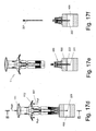
- Figs. 17a-17f The various operation stages of the device are illustrated in Figs. 17a-17f .
- the body of the patient is indicated by numeral 500.
- the initial stage of the device is shown in Figs. 17a , 14 , 15, and 16 .
- the device 1 is cocked and locked. More specifically, the cocked configuration is provided when the needle assembly 200 is fully positioned within the device 1, and the main spring 114 of the activator assembly 100 is loaded.
- the safety catch 111 is in its "locked” position (see also Fig. 6a ).
- a gap 160 exists between trigger 112 and barrel jacket 333.
- the gap provides a second safety means, as the device cannot be activated as long as this gap exists, even when safety catch 111 is turned into its "unlock” state (best shown in Fig. 6b ).
- the penetration depth Before the use of the device, the penetration depth may be tuned.
- the tuning selects between several penetration depths, and is performed by turning the turning element 441 to a selected angular position.
- Fig. 17b shows the device in its unlocked state as provided by turning the safety catch 111 (first safety means) into its unlocked position (i.e., turning it 90° from its initial locked position).
- the device 1 is in contact with the patient's body 500, however, it is still inoperable, as the gap 160 still exists.
- Fig. 17c shows the state of the device 1 just before its activation. More specifically, the second safety means is neutralized (in a manner which will be elaborated hereinafter) by the user applying a linear force 161 on the safety catch 111 directed to the patient's body 500, thereby eliminating gap 160.
- Figs. 17d , 18 , 19, and 20 show the device 1 just after its activation.
- the activation is provided by pulling trigger 112 in a proximal direction 167, i.e., away from patient's body 500.
- the activation of the device shots the stylet 221 (only its tip can be seen) and the cannula 222 together to the patient's body, more specifically to within the patient's bone 600. More specifically, the cannula 222 which encases the stylet 221 is pushed by the stylet into the patient's body, specifically to within the bone 600.
- Fig. 17e shows the device, after separating the main body of device 1 from the setting assembly 400.
- the setting assembly 400 supports the stylet 221 and cannula 222 in a stable configuration, attached to the patient's body 500.
- Fig. 17f shows the removal of the stylet 221 from within cannula 222.
- the sharp stylet 221 is used for providing a penetration power that pushes the cannula 222 to within bone 600.
- the stylet 221 is no longer necessary, as the channel to within the bone is already provided via cannula 222. Therefore stylet 221 is removed from within the cannula 222.
- fluid can be provided to within bone 600, via cannula 222, or a sample from the bone 600 can be obtained through cannula 222.
- the device of the invention provides a channel for fluids to within the bone 600.
- the device is very safe, as it comprises two safety measures that eliminate unintentional, accidental, or erroneous activation, or wrong operation.
- the device of the invention can be activated only when it is unlocked, is in contact with the patient's body and a force is applied on the device against the patient's body.
- the shot is possible only towards the patient's body, and a shot in and opposite direction (i.e., away from the patient's body or towards the operator of the device) is impossible. All these features are very important to ensure a reliable and safe operation.
- First tube 113 has holes 117a and 117b, having a diameter slightly larger than of balls 116a and 116b.
- Tube 113 also has two opposite stairs 120a and 120b.
- Each stair 120 has a front wall 121 for locking tube 113 within trigger 112, and two side walls 123 for guiding tube 113 within corresponding channels 140a and 140b within trigger 112 (best seen in Figs. 22 and 23 ), thereby enabling it to perform only a guided linear movement within trigger 112.
- First tube 113 also comprises two opposite first openings 132a and 132b (not shown) for joining between the first tube 113 of the activator assembly 100 and the second tube 331 of the barrel assembly 300.
- First tube 113 further comprises an external groove 133 that typically spans 90° of the periphery of first tube 113.
- Said external groove 133 comprises two recesses (not shown) that are located 90° respectively at the two ends of groove 133. Said two recesses are used for positioning the safety catch 111 in the "locked” and "unlocked” states of the device 1, respectively.
- Trigger 112 has two wings 138a and 138b, for enabling pulling the trigger only in one direction (away from the patient's body). Trigger 112 further comprises the two channels 140a and 140b, for enabling first tube 113 a limited guided linear movement within trigger 112. Two first snaps 139a and 139b (best seen in Figs. 22 and 24 ) are provided at the two channels 140a and 140b respectively. Each of said first snaps comprises a hook 141a, 141b which engages respectively the front wall 121a, 121b of the first tube 113, preventing trigger 112 from moving to a proximal direction relative to tube 113.
- the proximal direction is defined as the direction towards the operator of the device (i.e., to the direction of the safety catch 111, and away from the patient's body), while the distal direction is defined as the direction towards the patient's body (i.e., away from the operator and in a direction toward the tuning element 441).
- the two hooks 141 are slightly slanted 144a, 144b towards the distal direction as best shown in Fig. 22 .
- Trigger 112 further comprises two opposite round longitudinal grooves 147a and 147b. It should be noted, however, that the longitudinal grooves 147 do not span the whole length of trigger 112, but they end somewhat before the proximal end 153 of trigger 112 (best seen in Fig. 23 ).
- Trigger 112 further comprises two opposite second openings 155a and 155b (seen in Fig. 6a , 23, and 24 ).
- the two second openings 155 enable pulling the trigger 112 to the proximal direction relative to first tube 113, during the unlock state of the safety catch 111. On the other hand, such movement is prevented during the locked state of the safety catch 111.
- the safety catch 111 comprises two opposite indexing snaps 156a and 156b (shown in Fig. 3 , 6a and 6b ), at least one of them comprises an indexing protrusion 157. Said indexing protrusion 157 slides along external groove 133 of the first tube 113 upon turning of the safety catch 111, and is designed to rest within one of its recesses at the "locked” and “unlocked” states respectively.
- hammer 115 has a proximal portion 170 which enters the main spring 114, and a distal pin 171 for hitting the stylet 221 upon activation of the device.
- the hammer further comprises a peripheral round groove 172, for accepting balls 116a and 116b during the loaded state of the device. However, upon activation of the device, the balls 116 are released from within said groove 172.
- Figs. 4 and 5 show the activator assembly in its loaded state.
- the main spring 114 is compressed, balls 116a and 116b are pressed by the smooth portion 175 of trigger 112 and through holes 117a and 117b toward groove 172 of the hammer, thereby locking the hammer 115, and preventing it from moving to the distal direction.
- snaps 139a and 139b of trigger 112 lock the first tube 113 within the trigger 112, preventing trigger 112 from moving to the proximal direction (as shown in Figs 3 and 15 ).
- the safety catch is positioned in its locked state.
- Second tube 331 has second snaps 335a and 335b, for joining the barrel assembly 300 to activator assembly 100. Furthermore, the second tube further comprises two opposite stoppers 336a and 336b, used for preventing the release of the needle assembly 200 from the device 1 during its cocked state. The second tube further comprises two opposite rectangular windows 337a and 337b, whose length is larger than the length of corresponding windows in barrel jacket 333. Finally, the second tube 331 comprises a step 341 for pressing against the secondary spring 332.
- the secondary spring 332 and second tube 331 are inserted to within barrel jacket 333.
- the barrel jacket 333 has two opposite windows 340a and 340b, through which two opposite beveled cams 344a and 344b of elastic latches 334a and 334b respectively are entered.
- the cams maintain the barrel jacket 333 and the second tube 331 together, while letting the second tube 331 to make some limited longitudinal movement within barrel jacket 333, in view of the difference of length between windows 337 and 340.
- the spring 332 therefore causes a gap 160 (see Fig. 17b ), which is eliminated when the device is pressed against the patient's body 500.
- the size of the gap is essentially the difference between the lengths of windows 337 and 340.
- Barrel jacket 333 has still additional two opposite windows 345a and 345b, through which two respective hooks 346a and 346b enter. These hooks hold the setting assembly 400 within the device 1, specifically the second holder 442 during the cocked state. Barrel jacket 333 also comprises at its proximal end two opposite beveled fingers 349a and 349b, for opening snaps 139a and 139b of the trigger upon pressing the device against the patient's body, and elimination of the gap 160. Only the elimination of the gap and opening of the snaps 139 enable pulling the trigger 112 to activate the device (or in other words, release of the second safety measure mentioned before).
- the device is preferably designed to allow closure of the gap and activation of the device only when essentially all the distal surface of the setting assembly comes in contact with the patient's body, and in such a manner this ensure activation of the device only when positioned essentially perpendicular to the bone surface.
- the tuning element 441 has an external helical channel 443, enabling the definition of the trocar needle penetration depth, according to the angular position of the tuning element. More specifically, the helical portion is entered to within second holder 442, in such a manner that the snaps 444a and 444b engage the helical channel 443. More specifically, one or more fingers 445 of snaps 444 engage the channel 443. Optionally, two or more recesses within the channel are provided to enable seating of the one or more fingers within the channel in predefined positions respectively, each of such positions defines one specific penetration depth.
- the second holder 442 also has two opposite recesses 446a and 446b, to engage with the barrel assembly 300, by means of hooks 346a and 346b of elastic latches 334a and 334b. It should be noted, however, that the adjustment of he penetration depth by the setting assembly is optional.
- the setting assembly may be provided in a fixed pre-adjusted penetration depth, while further adjustment is not allowed.
- Figs. 17a-17f The body of the patient is indicated by numeral 500.
- the initial stage of the device is shown in Figs. 17a , 14 , 15, and 16 .
- the device 1 is cocked and locked. More specifically, the cocked configuration is provided when the needle assembly 200 is fully positioned within the device 1, and the main spring 114 of the activator assembly 100 is loaded.
- the safety catch 111 is in its "locked” position (see also Fig. 6a ).
- a gap 160 exists between trigger 112 and barrel jacket 333. The gap provides a second safety means, as the device cannot be activated as long as this gap exists, even when safety catch 111 is turned into its "unlock” state (best shown in Fig. 6b ).
- the penetration depth may be tuned by means of tuning element 441.
- the tuning selects between several penetration depths, and is performed by turning the turning element 441 to a selected angular position.
- Fig. 17b shows the device in its unlocked state as provided by turning the safety catch 111 (first safety means) into its unlocked position (i.e., turning it 90° from its initial locked position).
- the device 1 is in contact with the patient's body 500, however, it is still inoperable, as the gap 160 still exists.
- Fig. 17c shows the state of the device 1 just before its activation. More specifically, the second safety means is neutralized by the user applying a linear distal direction force 161 on the safety catch 111 directed to the patient's body 500, thereby eliminating gap 160. The elimination of the gap opens the snaps 139a and 139b, thereby uncoupling them from first tube 113. This enables activation of the device by pulling trigger 112 to the proximal direction.
- Fig. 17d shows the device 1 just after its activation.
- the activation is provided by pulling trigger 112 in a proximal direction 167 away from patient's body 500.
- the activation of the device cause the balls 116a and 116b to release hammer 115, which is in turn pushed by the previously loaded main spring 114 in the distal direction.
- Hammer 115 hits the stylet 221, which in turn also pushes the cannula 222 in the distal direction.
- the stylet 221 and cannula 222 leave the first holder 223, and settle in second holder 442.
- the hammer 115 simultaneously hits the first holder 223, pushing it also in the distal direction.
- the first holder 223 in turn hits the beveled cams 344 causing uncoupling of the setting assembly 400 from barrel assembly 300.
- the stylet 221 and cannula 222 together penetrate the patient's body, more specifically to within the patient's bone 600.
- Fig. 17e shows the device, after separating the main body of the device 1 from the setting assembly 400.
- the setting assembly 400 supports the stylet 221 and cannula 222 in a stable configuration, attached to the patient's body 500.
- Fig. 17f shows the removal of the stylet 221 from within cannula 222.
- the sharp stylet 221 is used for providing a penetration power that pushes the cannula 222 to within bone 600.
- the stylet 221 is no longer necessary, as the channel to within the bone is already provided via cannula 222. Therefore stylet 221 is removed from within the cannula 222.
- fluid can be provided to within bone 600, via cannula 222, or a sample from the bone 600 can be obtained through cannula 222.
Landscapes
- Health & Medical Sciences (AREA)
- Life Sciences & Earth Sciences (AREA)
- Surgery (AREA)
- Molecular Biology (AREA)
- General Health & Medical Sciences (AREA)
- Pathology (AREA)
- Engineering & Computer Science (AREA)
- Biomedical Technology (AREA)
- Heart & Thoracic Surgery (AREA)
- Medical Informatics (AREA)
- Veterinary Medicine (AREA)
- Animal Behavior & Ethology (AREA)
- Public Health (AREA)
- Nuclear Medicine, Radiotherapy & Molecular Imaging (AREA)
- Orthopedic Medicine & Surgery (AREA)
- Gastroenterology & Hepatology (AREA)
- Hematology (AREA)
- Immunology (AREA)
- Rheumatology (AREA)
- Infusion, Injection, And Reservoir Apparatuses (AREA)
Description
- The present disclosure relates to instruments for the insertion of a cannula-stylet into the marrow of a bone, for the purpose of administration of drugs fluids and blood or for aspirating samples of bone marrow through said cannula. More specifically, the invention relates to such a device that comprises more safety means than prior art devices, and which provides a better support for the cannula over the patient's body after the activation of the device.
- Intraosseous injection devices (IID) for causing a cannula and at least a portion of stylet (hereinafter the pair of cannula and stylet are also referred to as "trocar needle") to penetrate into a bone are well known in the art. Such devices are typically used in life saving cases where the injection of drugs to the blood circuitry is required, while it is difficult for the medical staff to locate the patient's vein within a reasonable time. This device is also used for the extraction of a sample from a patient's bone marrow.
-
US 2010/0160868 ,US 2003/0225344 ,US 2010/0298831 ,US 2008/0208136 ,US 2006/0015066 ,US 2010/0160867 ,US 2010/0152616 ,US 2010/0137740 ,US 2006/0052790 ,US 2005/0171504 ,US 2003/0225411 , andUS 2010/0312246 , all describe some sorts of intraosseous devices.US 2005/165403 A1 discloses an intraosseous device which forms the basis of the preamble ofclaim 1. - It has been found, however, that such devices suffer from safety problems and from improper of operation problems. For example, there are known cases in which the doctor has activated the device in the opposite direction, causing a portion of the trocar needle to penetrate the doctor's body instead of the patient's body. In other cases, devices have been early activated, before positioning the device at the exact point over the patient's body.
- Furthermore, prior art devices do not provide a very stable support to the cannula, after causing its penetration into the patient's bone.
- All the above drawbacks endanger both the patient's life and the device operator, as they involve injury to the operator, loss of the whole device or components thereof (most of such devices are designed for one-time use, and the operator may not have a spare device), or a loss of precious time. Moreover, even if the trocar needle has successfully inserted into the bone, the administration of the drugs into the bone may not succeed due to instability of the cannula, after the penetration operation.
- It is therefore an object of the present invention to provide an intraosseous device which is safer both to the operator and to the patient. More specifically it is an object of the invention to provide a device whose various known types of erroneous operation are eliminated, or at least minimized.
- It is another object of the present invention to provide a device which is more reliable in operation.
- It is still another object of the present invention to provide a device provides support to the cannula over the patient's body, after activation and disconnection of the device from the cannula.
- Other objects and advantages of the invention will become apparent as the description proceeds.
-
Claim 1 defines the invention and the dependent claims disclose the preferred embodiments. The invention relates to a device for the insertion of a cannula into a bone of a patient, which comprises: (a). an activator assembly for activating the device; (b). needle assembly which comprises a stylet and cannula; (c). barrel assembly for containing said stylet and cannula in a loaded state prior to the device activation; and (d). a setting assembly for adjusting the penetration depth of said cannula into the patient's bone; wherein: (e). said activator assembly comprises a first safety mechanism in a form of a safety catch that prevents activation of the device unless said safety catch is released; (f). said activator assembly comprises a trigger that triggers activation of the device only if pulled toward a proximal direction, while pulling to the distal direction is prevented, thereby eliminating reverse direction activation; (g). the device comprises a second safety mechanism that prevents activation of the device by locking it unless said setting assembly is pushed against the patient's body, thereby causing closure of a gap in the device between a jacket which is located in said barrel assembly and said activator assembly, hence the device becomes ready for activation only when placed properly against the patient's body. - Preferably, said gap between said barrel assembly and said activator assembly is formed by means of a secondary spring which is located between said two assemblies.
- 3Preferably, when the device is pushed against the patient's body, but released without triggering, the gap is recreated, and the device becomes locked again.
- Preferably, said needle assembly is maintained in a loaded state within the device by means of a loaded main spring.
- Preferably, said setting assembly automatically separate from the main body of the device together with said needle assembly after activation of the device, and said setting assembly remains on the patient's body to support, stabilize, fix and maintain the cannula in place.
- Preferably, the stylet is removed from the cannula after activation of the device, leaving the cannula penetrated within the bone, thereby producing a channel from the exterior of the patient's body to within the medullary cavity of the bone.
- Preferably, said first safety mechanism is released by means of rotating relative to the rest of the device.
- Preferably, said stylet is maintained within said cannula, before activation of the device.
- Preferably, said setting assembly comprises a turning element with a thread, which defines the depth of penetration by means of rotation.
- Preferably, said needle assembly is pushed toward the bone upon activation of the device by means of a hammer.
- Preferably, said needle assembly further comprises a first holder, said first holder releases the stylet and cannula after the triggering of the device.
- Preferably, said first holder automatically releases the setting assembly after the triggering of the device and insertion of said stylet and cannula into the bone.
- Preferably, said needle assembly comprises a needle holder that holds the needle aligned in place during the loaded state of the device.
- Preferably, said second safety mechanism allows activation of the device only when positioned essentially perpendicular to the bone surface.
- Optionally, the setting assembly is pre-adjusted to a fixed penetration depth (i.e., a pre-adjustment by the manufacturer to a specific depth that does not enable the user making any further adjustment).
- In the drawings:
-
Fig. 1 shows the general structure of the IID device of the present invention; -
Fig. 2 illustrates the four main assemblies of the IID device of the present invention; -
Fig. 3 is an exploded isometric view of the activator assembly; -
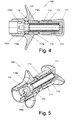
Fig. 4 is a cross-sectional view of the activator assembly; -
Fig. 5 is a three quarter cross-sectional view of the activator assembly in its cocked configuration; -
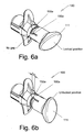
Fig. 6a shows the safety catch of the device in its locked position; -
Fig. 6b shows the safety catch of the device in its unlocked position; -
Fig. 7 shows an exploded view of the barrel assembly; -
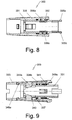
Fig. 8 is a cross sectional front view of the barrel assembly; -
Fig. 9 is a cross sectional top view of the barrel assembly; -
Fig. 10 shows an exploded view of the setting assembly; -
Fig. 11 is a cross sectional view of the setting assembly; -
Fig. 12 shows an exploded view of the needle assembly; -
Fig. 13 is a cross sectional view of the needle assembly; -
Fig. 14 is a cross sectional front view of the device of the invention in its cocked state; -
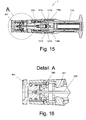
Fig. 15 is a cross sectional top view of the device of the invention in its cocked state; -
Fig. 16 is a detail view of A ofFig. 15 ; -
Fig. 17a shows the device of the invention in its initial stage; -
Fig. 17b shows the device of the invention in its unlocked state as provided by turning the safety catch into its unlocked position; -
Fig. 17c shows the device of the invention just before its activation; -
Fig. 17d shows the device just after its activation; -
Fig. 17e shows the device of the invention after separation of the main body from the setting assembly; -
Fig. 17f shows the removal of the stylet from within the cannula, after the completion of the penetration; -
Fig. 18 is a front cross sectional viewFig. 17d , showing the device just after its activation; -
Fig. 19 is a cross sectional view made along cutting plane B-B ofFig. 17d ; -
Fig. 20 is a detailed view of section C ofFig. 19 ; -
Fig. 21 shows the stylet and cannula of the device; -
Fig. 22 shows a front view of the trigger of the device; -
Fig. 23 is a three quarter cross section of the trigger of the device; and -
Fig. 24 is a rear view of the trigger of the device. - The present invention relates to an intraosseous injection device (IID). The IID of the invention enables introduction of fluid into the bone marrow. As will be elaborated hereinafter, the device of the present invention provides a cannula into the bone marrow. Thereafter, the fluid can be provided through said cannula to within the bone marrow. The IID of the invention is typically used in emergency cases, where injection into the bone marrow provides the fastest effect. Moreover, the device can be used in cases when there is a need to obtain a sample from the bone marrow, for diagnosis purposes.
- The IID is essentially a spring loaded device, that upon activation "shoots" a portion of the needle assembly by the force generated by the spring's expansion, causing a stylet and cannula of the needle assembly to penetrate into the bone. As will be shown in detail, the device comprises two safety measures for preventing erroneous or accidental operation. The first safety measure of the IID requires the user to make a 90° turn of a safety catch, and the second safety measure requires the user to apply a linear force directed against the patient's body. Only after the release of said two safety measures, the device is operable. In such a manner, erroneous or accidental operations, which happened from time to time, are prevented. More specifically, the safety measures enable the stylet and cannula of the needle assembly to be applied only toward the bone, and not in the opposite direction, as happened in prior art devices.
-
Fig. 1 shows theIID 1 of the present invention, whileFig. 2 shows the various assemblies of theIID 1. In general,IID 1 comprises four assemblies, as follows:Activator assembly 100,needle assembly 200,barrel assembly 300, and settingassembly 400. - The
activator assembly 100, which is shown inFigs. 3 ,4 ,5 , and6 is used for activating the device. It comprises: (a)first safety catch 111, for releasing the device from a locked state into an operable state; (b)trigger 112 for triggering the device; (c)first tube 113; (d)main spring 114, (e)hammer 115; and (f) twoballs - The
needle assembly 200, which is shown inFigs. 12, 13 ,17f , and21 , comprises: (a) stylet 221 (best seen inFig. 21 ); (b)cannula 222; and (c)first holder 223. Thefirst holder 223 comprises snaps 224a and 224b for holding thecannula 222. Thestylet 221 is typically located withincannula 222, and upon activation of the device, these two elements together penetrate the patient's body towards the bone. Thefirst holder 223 remains within the device even after its activation. Moreover, said first holder also holds the needle aligned in place during the loaded state of the device. - The
barrel assembly 300, which is shown inFigs. 7 ,8, and 9 is used for directing the trocar needle toward the body, for releasing the second safety catch, and releasing, upon activation of the device, of the settingassembly 400,stylet 221 andcannula 222 toward the body. Thebarrel assembly 300 comprises: (a)second tube 331; (b)secondary spring 332; (c)barrel jacket 333; and (d) twoelastic latches - The setting
assembly 400 which is shown inFigs. 10 and 11 is used for tuning the depth of the penetration. Moreover, after the activation of the device, the settingassembly 400 is released from the main body of thedevice 1, together with thecannula 222 andstylet 221, and it maintains the cannula and stylet in a stable state on the patient's body. The settingassembly 400 comprises: (a)tuning element 441; and (b)second holder 442. - The various operation stages of the device are illustrated in
Figs. 17a-17f . The body of the patient is indicated bynumeral 500. The initial stage of the device is shown inFigs. 17a ,14 ,15, and 16 . In the initial stage, thedevice 1 is cocked and locked. More specifically, the cocked configuration is provided when theneedle assembly 200 is fully positioned within thedevice 1, and themain spring 114 of theactivator assembly 100 is loaded. During the locked configuration, thesafety catch 111 is in its "locked" position (see alsoFig. 6a ). Moreover, agap 160 exists betweentrigger 112 andbarrel jacket 333. As will be elaborated, the gap provides a second safety means, as the device cannot be activated as long as this gap exists, even whensafety catch 111 is turned into its "unlock" state (best shown inFig. 6b ). - Before the use of the device, the penetration depth may be tuned. The tuning selects between several penetration depths, and is performed by turning the
turning element 441 to a selected angular position. -
Fig. 17b shows the device in its unlocked state as provided by turning the safety catch 111 (first safety means) into its unlocked position (i.e., turning it 90° from its initial locked position). Thedevice 1 is in contact with the patient'sbody 500, however, it is still inoperable, as thegap 160 still exists. -
Fig. 17c shows the state of thedevice 1 just before its activation. More specifically, the second safety means is neutralized (in a manner which will be elaborated hereinafter) by the user applying alinear force 161 on thesafety catch 111 directed to the patient'sbody 500, thereby eliminatinggap 160. -
Figs. 17d ,18 ,19, and 20 show thedevice 1 just after its activation. The activation is provided by pullingtrigger 112 in aproximal direction 167, i.e., away from patient'sbody 500. The activation of the device shots the stylet 221 (only its tip can be seen) and thecannula 222 together to the patient's body, more specifically to within the patient'sbone 600. More specifically, thecannula 222 which encases thestylet 221 is pushed by the stylet into the patient's body, specifically to within thebone 600. -
Fig. 17e shows the device, after separating the main body ofdevice 1 from the settingassembly 400. By this separation, the settingassembly 400 supports thestylet 221 andcannula 222 in a stable configuration, attached to the patient'sbody 500. -
Fig. 17f shows the removal of thestylet 221 from withincannula 222. As previously noted, thesharp stylet 221 is used for providing a penetration power that pushes thecannula 222 to withinbone 600. After completion of the penetration, thestylet 221 is no longer necessary, as the channel to within the bone is already provided viacannula 222. Thereforestylet 221 is removed from within thecannula 222. Next, by means of a syringe, or another medical device, fluid can be provided to withinbone 600, viacannula 222, or a sample from thebone 600 can be obtained throughcannula 222. - As shown, the device of the invention provides a channel for fluids to within the
bone 600. The device is very safe, as it comprises two safety measures that eliminate unintentional, accidental, or erroneous activation, or wrong operation. The device of the invention can be activated only when it is unlocked, is in contact with the patient's body and a force is applied on the device against the patient's body. Furthermore, the shot is possible only towards the patient's body, and a shot in and opposite direction (i.e., away from the patient's body or towards the operator of the device) is impossible. All these features are very important to ensure a reliable and safe operation. - The
activator assembly 100 will now be described in more detail, with reference toFigs. 3 ,4, and 5 .First tube 113 hasholes balls Tube 113 also has twoopposite stairs tube 113 withintrigger 112, and two side walls 123 for guidingtube 113 withincorresponding channels Figs. 22 and23 ), thereby enabling it to perform only a guided linear movement withintrigger 112.First tube 113 also comprises two oppositefirst openings 132a and 132b (not shown) for joining between thefirst tube 113 of theactivator assembly 100 and thesecond tube 331 of thebarrel assembly 300. In other words, the openings enable joining of theactivator assembly 100 and thebarrel assembly 300 in a manner that will be elaborated hereinafter.First tube 113 further comprises anexternal groove 133 that typically spans 90° of the periphery offirst tube 113. Saidexternal groove 133 comprises two recesses (not shown) that are located 90° respectively at the two ends ofgroove 133. Said two recesses are used for positioning thesafety catch 111 in the "locked" and "unlocked" states of thedevice 1, respectively. -
Trigger 112 has twowings Trigger 112 further comprises the twochannels trigger 112. Twofirst snaps Figs. 22 and24 ) are provided at the twochannels hook front wall first tube 113, preventingtrigger 112 from moving to a proximal direction relative totube 113. Hereinafter, the proximal direction is defined as the direction towards the operator of the device (i.e., to the direction of thesafety catch 111, and away from the patient's body), while the distal direction is defined as the direction towards the patient's body (i.e., away from the operator and in a direction toward the tuning element 441). The two hooks 141 are slightly slanted 144a, 144b towards the distal direction as best shown inFig. 22 .Trigger 112 further comprises two opposite roundlongitudinal grooves trigger 112, but they end somewhat before theproximal end 153 of trigger 112 (best seen inFig. 23 ). The potion oftrigger 112 where there is no groove will be referred herein as thesmooth surface 175.Trigger 112 further comprises two oppositesecond openings Fig. 6a ,23, and 24 ). The two second openings 155 enable pulling thetrigger 112 to the proximal direction relative tofirst tube 113, during the unlock state of thesafety catch 111. On the other hand, such movement is prevented during the locked state of thesafety catch 111. - The
safety catch 111 comprises twoopposite indexing snaps Fig. 3 ,6a and 6b ), at least one of them comprises an indexing protrusion 157. Said indexing protrusion 157 slides alongexternal groove 133 of thefirst tube 113 upon turning of thesafety catch 111, and is designed to rest within one of its recesses at the "locked" and "unlocked" states respectively. - With reference to
Fig. 3 ,hammer 115 has aproximal portion 170 which enters themain spring 114, and adistal pin 171 for hitting thestylet 221 upon activation of the device. The hammer further comprises a peripheralround groove 172, for acceptingballs groove 172. -
Figs. 4 and 5 show the activator assembly in its loaded state. Themain spring 114 is compressed,balls smooth portion 175 oftrigger 112 and throughholes groove 172 of the hammer, thereby locking thehammer 115, and preventing it from moving to the distal direction. Furthermore, snaps 139a and 139b oftrigger 112 lock thefirst tube 113 within thetrigger 112, preventingtrigger 112 from moving to the proximal direction (as shown inFigs 3 and15 ). Finally, in this state the safety catch is positioned in its locked state. - The
barrel assembly 300 is shown inFigs. 7 ,8, and 9 .Second tube 331 hassecond snaps barrel assembly 300 toactivator assembly 100. Furthermore, the second tube further comprises twoopposite stoppers needle assembly 200 from thedevice 1 during its cocked state. The second tube further comprises two oppositerectangular windows 337a and 337b, whose length is larger than the length of corresponding windows inbarrel jacket 333. Finally, thesecond tube 331 comprises astep 341 for pressing against thesecondary spring 332. - The
secondary spring 332 andsecond tube 331 are inserted to withinbarrel jacket 333. Thebarrel jacket 333 has twoopposite windows 340a and 340b, through which two oppositebeveled cams elastic latches barrel jacket 333 and thesecond tube 331 together, while letting thesecond tube 331 to make some limited longitudinal movement withinbarrel jacket 333, in view of the difference of length betweenwindows spring 332 therefore causes a gap 160 (seeFig. 17b ), which is eliminated when the device is pressed against the patient'sbody 500. The size of the gap is essentially the difference between the lengths ofwindows Barrel jacket 333 has still additional twoopposite windows 345a and 345b, through which tworespective hooks assembly 400 within thedevice 1, specifically thesecond holder 442 during the cocked state.Barrel jacket 333 also comprises at its proximal end two oppositebeveled fingers snaps gap 160. Only the elimination of the gap and opening of the snaps 139 enable pulling thetrigger 112 to activate the device (or in other words, release of the second safety measure mentioned before). Moreover, the device is preferably designed to allow closure of the gap and activation of the device only when essentially all the distal surface of the setting assembly comes in contact with the patient's body, and in such a manner this ensure activation of the device only when positioned essentially perpendicular to the bone surface. - The setting
assembly 400 will now be described, with reference toFigs. 10 and 11 . Thetuning element 441 has an externalhelical channel 443, enabling the definition of the trocar needle penetration depth, according to the angular position of the tuning element. More specifically, the helical portion is entered to withinsecond holder 442, in such a manner that the snaps 444a and 444b engage thehelical channel 443. More specifically, one ormore fingers 445 ofsnaps 444 engage thechannel 443. Optionally, two or more recesses within the channel are provided to enable seating of the one or more fingers within the channel in predefined positions respectively, each of such positions defines one specific penetration depth. Thesecond holder 442 also has two opposite recesses 446a and 446b, to engage with thebarrel assembly 300, by means ofhooks elastic latches - The activation of the device will now be described. The various operation stages of the device are illustrated in
Figs. 17a-17f . The body of the patient is indicated bynumeral 500. The initial stage of the device is shown inFigs. 17a ,14 ,15, and 16 . In the initial stage, thedevice 1 is cocked and locked. More specifically, the cocked configuration is provided when theneedle assembly 200 is fully positioned within thedevice 1, and themain spring 114 of theactivator assembly 100 is loaded. During the locked configuration, thesafety catch 111 is in its "locked" position (see alsoFig. 6a ). Moreover, agap 160 exists betweentrigger 112 andbarrel jacket 333. The gap provides a second safety means, as the device cannot be activated as long as this gap exists, even whensafety catch 111 is turned into its "unlock" state (best shown inFig. 6b ). - Before the use of the device, the penetration depth may be tuned by means of tuning
element 441. The tuning selects between several penetration depths, and is performed by turning theturning element 441 to a selected angular position. -
Fig. 17b shows the device in its unlocked state as provided by turning the safety catch 111 (first safety means) into its unlocked position (i.e., turning it 90° from its initial locked position). Thedevice 1 is in contact with the patient'sbody 500, however, it is still inoperable, as thegap 160 still exists. -
Fig. 17c shows the state of thedevice 1 just before its activation. More specifically, the second safety means is neutralized by the user applying a lineardistal direction force 161 on thesafety catch 111 directed to the patient'sbody 500, thereby eliminatinggap 160. The elimination of the gap opens thesnaps first tube 113. This enables activation of the device by pullingtrigger 112 to the proximal direction. -
Fig. 17d shows thedevice 1 just after its activation. As mentioned, the activation is provided by pullingtrigger 112 in aproximal direction 167 away from patient'sbody 500. The activation of the device cause theballs hammer 115, which is in turn pushed by the previously loadedmain spring 114 in the distal direction.Hammer 115 hits thestylet 221, which in turn also pushes thecannula 222 in the distal direction. Thestylet 221 andcannula 222 leave thefirst holder 223, and settle insecond holder 442. Thehammer 115 simultaneously hits thefirst holder 223, pushing it also in the distal direction. Thefirst holder 223 in turn hits thebeveled cams 344 causing uncoupling of the settingassembly 400 frombarrel assembly 300. Following the process above, thestylet 221 andcannula 222 together penetrate the patient's body, more specifically to within the patient'sbone 600. -
Fig. 17e shows the device, after separating the main body of thedevice 1 from the settingassembly 400. By this separation, the settingassembly 400 supports thestylet 221 andcannula 222 in a stable configuration, attached to the patient'sbody 500. -
Fig. 17f shows the removal of thestylet 221 from withincannula 222. As previously noted, thesharp stylet 221 is used for providing a penetration power that pushes thecannula 222 to withinbone 600. After completion of the penetration, thestylet 221 is no longer necessary, as the channel to within the bone is already provided viacannula 222. Thereforestylet 221 is removed from within thecannula 222. Next, by means of a syringe, or another medical device, fluid can be provided to withinbone 600, viacannula 222, or a sample from thebone 600 can be obtained throughcannula 222. - While some embodiments of the invention have been described by way of illustration, it will be apparent that the invention can be carried out with many modifications, variations and adaptations, and with the use of numerous equivalents or alternative solutions that are within the scope of persons skilled in the art, without departing from the scope of the invention as defined by the claims.
Claims (15)
- Device (1) for the insertion of a cannula (222) into a bone of a patient, which comprises:a. an activator assembly (100) for activating the device;b. a needle assembly (200) which comprises a stylet (221) and cannula (222);c. a barrel assembly (300) for containing said stylet and cannula in a loaded state prior to the device activation; andd. a setting assembly (400) for adjusting the penetration depth of said cannula into the patient's bone;e. said activator assembly comprises a first safety mechanism in a form of a safety catch (111) that prevents activation of the device unless said safety catch is released;f. said activator assembly comprises a trigger (112) that triggers activation of the device only upon application of of a pulling force (167) in a proximal direction; the device is characterised in that: pulling to the distal direction is prevented, thereby eliminating any possibility of reverse direction activation by applying a force in a distal direction;g. the device comprises a second safety mechanism that prevents activation of the device by locking it unless a pushing force in a distal direction (161) is applied on the safety catch (111) causing said setting assembly to press against the patient's body (500), thereby causing closure of a gap (160) in the device between a jacket (333) which is located in said barrel assembly and said activator assembly, hence the device becomes ready for activation only when placed properly against the patient's body; andh. wherein said pushing and pulling forces in the distal and proximal directions, respectively, are applied at least partially simultaneously.
- A device according to claim 1, wherein said gap (160) between said barrel assembly and said activator assembly is a visually seen gap which is formed by means of a secondary spring (332) which is located between said two assemblies.
- A device according to claim 1, wherein when the device is pushed in the distal direction against the patient's body, but then released without triggering, the gap is reopened, and the device becomes locked again.
- A device according to claim 1, wherein said needle assembly is maintained in a loaded state within the device by means of a loaded main spring (114).
- A device according to claim 1, wherein said setting assembly (400) automatically separates from the main body of the device together with said needle assembly after activation of the device, and said setting assembly remains on the patient's body (500) to support, stabilize, fix and maintain the cannula in place.
- A device according to claim 1, wherein the stylet (221) is removed from the cannula after activation of the device, leaving the cannula penetrated within the bone (600), thereby producing a channel from the exterior of the patient's body to within the medullary cavity of the bone.
- A device according to claim 1, wherein said first safety mechanism is released by means of rotating relative to the rest of the device.
- A device according to claim 1, wherein said stylet is maintained within said cannula, before activation of the device.
- A device according to claim 1, wherein said setting assembly comprises a turning element (441) with a thread (443) which defines the depth of penetration by means of rotation.
- A device according to claim 1, wherein said needle assembly is pushed toward the bone activation of the device by means of a hammer (115).
- A device according to claim 1, wherein said needle assembly further comprises a first holder (223), said first holder releases the stylet and cannula after the triggering of the device.
- A device according to claim 11, wherein said first holder automatically releases the setting assembly after the triggering of the device and insertion of said stylet and cannula into the bone.
- A device according to claim 1, wherein said needle assembly comprises a needle holder (223) that holds the needle aligned in place during the loaded state of the device.
- A device according to claim 1, wherein said second safety mechanism allows activation of the device only when positioned essentially perpendicular to the bone surface.
- A device according to claim 1, wherein the setting assembly is pre-adjusted to a fixed penetration depth.
Priority Applications (1)
| Application Number | Priority Date | Filing Date | Title |
|---|---|---|---|
| PL12770984T PL2696917T3 (en) | 2011-04-11 | 2012-04-02 | Intraosseous device for inserting a cannula into a bone |
Applications Claiming Priority (2)
| Application Number | Priority Date | Filing Date | Title |
|---|---|---|---|
| IL212263A IL212263A (en) | 2011-04-11 | 2011-04-11 | Intraosseous device for inserting a cannula into a bone |
| PCT/IL2012/000141 WO2012140645A1 (en) | 2011-04-11 | 2012-04-02 | Intraosseous device for inserting a cannula into a bone |
Publications (3)
| Publication Number | Publication Date |
|---|---|
| EP2696917A1 EP2696917A1 (en) | 2014-02-19 |
| EP2696917A4 EP2696917A4 (en) | 2014-11-19 |
| EP2696917B1 true EP2696917B1 (en) | 2020-06-17 |
Family
ID=44262634
Family Applications (1)
| Application Number | Title | Priority Date | Filing Date |
|---|---|---|---|
| EP12770984.8A Active EP2696917B1 (en) | 2011-04-11 | 2012-04-02 | Intraosseous device for inserting a cannula into a bone |
Country Status (8)
| Country | Link |
|---|---|
| US (1) | US9173679B2 (en) |
| EP (1) | EP2696917B1 (en) |
| JP (1) | JP6282583B2 (en) |
| CN (1) | CN103648551B (en) |
| ES (1) | ES2802679T3 (en) |
| IL (1) | IL212263A (en) |
| PL (1) | PL2696917T3 (en) |
| WO (1) | WO2012140645A1 (en) |
Families Citing this family (26)
| Publication number | Priority date | Publication date | Assignee | Title |
|---|---|---|---|---|
| AR070764A1 (en) * | 2007-12-07 | 2010-05-05 | Pyng Medical Corp | APPLIANCES AND METHODS TO ENTER OSEOS PORTALS |
| EP2797645B1 (en) | 2011-12-28 | 2017-10-18 | Xerem Medical Ltd. | System and method for blood filtering and/or treatment |
| CN106659487B (en) * | 2014-05-19 | 2019-05-28 | 生物技术部秘书 | Disposable intraosseous puncture device and method thereof |
| CN105268089B (en) * | 2014-06-13 | 2018-07-13 | 上海市浦东医院 | A kind of intrabone infusion device |
| JP2017500981A (en) * | 2014-11-14 | 2017-01-12 | ライト メディカル テクノロジー インコーポレイテッドWright Medical Technology, Inc. | Guide punch for talar augment |
| US9814516B2 (en) * | 2014-11-17 | 2017-11-14 | Covidien Lp | Deployment mechanisms for multi-function surgical instruments |
| CN105107063B (en) * | 2015-09-23 | 2019-03-01 | 上海必趣医疗科技有限公司 | The adjustable syringe of disposable medical cosmetology depth |
| WO2017211493A1 (en) * | 2016-06-10 | 2017-12-14 | Fresenius Kabi Deutschland Gmbh | Cannulation device |
| AU2017350937B2 (en) | 2016-10-27 | 2021-12-23 | C. R. Bard, Inc. | Intraosseous access device |
| RU193231U1 (en) * | 2019-06-04 | 2019-10-18 | Российская Федерация, от имени которой выступает Министерство обороны Российской Федерации | DEVICE FOR INTRACOSTIC INFUSION |
| CN120531451A (en) | 2019-09-27 | 2025-08-26 | 巴德阿克塞斯系统股份有限公司 | Self-advancement feature of intraosseous devices |
| EP4031017B1 (en) | 2019-09-27 | 2024-10-30 | Bard Access Systems, Inc. | Step needle for intraosseous access device |
| US11633214B2 (en) | 2019-09-27 | 2023-04-25 | Bard Access Systems, Inc. | Various operating mechanisms for intraosseous access medical devices and methods thereof |
| EP4034008B1 (en) | 2019-09-27 | 2025-06-04 | Bard Access Systems, Inc. | Constant-torque intraosseous access devices |
| CN110755140B (en) * | 2019-11-28 | 2024-09-24 | 中国人民解放军陆军特色医学中心 | Sternum transfusion needle |
| CN113317840A (en) | 2020-02-28 | 2021-08-31 | 巴德阿克塞斯系统股份有限公司 | Flexible intra-osseous obturator |
| CN113520512B (en) | 2020-04-21 | 2026-01-02 | 巴德阿克塞斯系统股份有限公司 | Reusable push-activated intraosseous access device |
| US11998237B2 (en) | 2020-06-03 | 2024-06-04 | Bard Access Systems, Inc. | Intraosseous device including a sensing obturator |
| WO2022016095A1 (en) | 2020-07-17 | 2022-01-20 | Bard Access Systems, Inc. | Safety mechanism |
| CN114098918B (en) | 2020-08-25 | 2025-12-12 | 巴德阿克塞斯系统股份有限公司 | Angled intraosseous access system |
| EP4203821B1 (en) | 2020-09-01 | 2025-10-29 | Bard Access Systems, Inc. | Retractable intraosseous access system |
| CN215839325U (en) | 2020-09-09 | 2022-02-18 | 巴德阿克塞斯系统股份有限公司 | Suction device for an intraosseous access system |
| CN114903553A (en) | 2021-02-08 | 2022-08-16 | 巴德阿克塞斯系统股份有限公司 | Intraosseous access system and method for drilling through bone |
| CN113317849B (en) * | 2021-04-22 | 2022-09-27 | 卫飞 | Bone puncture needle emitter |
| IL284380A (en) | 2021-06-24 | 2023-01-01 | Waismed Ltd | Manual intraosseous device and method for inserting an opening in bone to a specified depth |
| CN114533145B (en) * | 2022-03-02 | 2023-07-14 | 浙江伽奈维医疗科技有限公司 | a biopsy gun |
Citations (1)
| Publication number | Priority date | Publication date | Assignee | Title |
|---|---|---|---|---|
| US20050165403A1 (en) * | 2004-01-26 | 2005-07-28 | Miller Larry J. | Impact-driven intraosseous needle |
Family Cites Families (16)
| Publication number | Priority date | Publication date | Assignee | Title |
|---|---|---|---|---|
| US7347840B2 (en) * | 2000-03-02 | 2008-03-25 | Pyng Medical Corp. | Patch for locating a target zone for penetration |
| IL147983A (en) * | 2002-02-04 | 2007-12-03 | Michael Flint | Repeated use trocar-needle insertion instrument and loading tool |
| US7811260B2 (en) | 2002-05-31 | 2010-10-12 | Vidacare Corporation | Apparatus and method to inject fluids into bone marrow and other target sites |
| JP4938979B2 (en) | 2002-05-31 | 2012-05-23 | ヴァイダケア、コーパレイシャン | Apparatus and method for accessing bone marrow |
| US20060015066A1 (en) * | 2004-05-17 | 2006-01-19 | Turieo Melanie J | Intraosseous infusion device |
| US20060276772A1 (en) * | 2005-06-06 | 2006-12-07 | Sherwood Services Ag | Bayonet release of safety shield for needle tip |
| EP1772099B8 (en) * | 2005-10-08 | 2011-10-05 | Roche Diagnostics GmbH | Piercing system |
| WO2008065646A1 (en) * | 2006-11-28 | 2008-06-05 | Medingo Ltd. | An insertion device and method for inserting a subcutaneously insertable element into a body |
| WO2008155377A1 (en) * | 2007-06-20 | 2008-12-24 | Unomedical A/S | Cannula insertion device with automatic needle retraction comprising only one spring |
| US8409145B2 (en) | 2007-09-17 | 2013-04-02 | Tecpharma Licensing Ag | Insertion devices for infusion devices |
| US20100152616A1 (en) * | 2007-11-20 | 2010-06-17 | Niyazi Beyhan | Devices and methods for safely accessing bone marrow and other tissues |
| AR070764A1 (en) | 2007-12-07 | 2010-05-05 | Pyng Medical Corp | APPLIANCES AND METHODS TO ENTER OSEOS PORTALS |
| CN101945680B (en) * | 2008-01-15 | 2013-08-21 | 贝克顿·迪金森公司 | Pen needle assembly with needle insertion mechanism |
| US20100015265A1 (en) * | 2008-07-21 | 2010-01-21 | United Technologies Corporation | Pressure bladder and method for fabrication |
| CN201353183Y (en) * | 2009-02-19 | 2009-12-02 | 赵文海 | Intelligent puncture appliance |
| CN101703822B (en) * | 2009-12-14 | 2012-07-25 | 杨力 | Marrow liquid-injecting gun |
-
2011
- 2011-04-11 IL IL212263A patent/IL212263A/en active IP Right Grant
-
2012
- 2012-04-02 PL PL12770984T patent/PL2696917T3/en unknown
- 2012-04-02 US US14/009,937 patent/US9173679B2/en active Active
- 2012-04-02 JP JP2014504447A patent/JP6282583B2/en active Active
- 2012-04-02 WO PCT/IL2012/000141 patent/WO2012140645A1/en not_active Ceased
- 2012-04-02 ES ES12770984T patent/ES2802679T3/en active Active
- 2012-04-02 CN CN201280017799.4A patent/CN103648551B/en active Active
- 2012-04-02 EP EP12770984.8A patent/EP2696917B1/en active Active
Patent Citations (1)
| Publication number | Priority date | Publication date | Assignee | Title |
|---|---|---|---|---|
| US20050165403A1 (en) * | 2004-01-26 | 2005-07-28 | Miller Larry J. | Impact-driven intraosseous needle |
Also Published As
| Publication number | Publication date |
|---|---|
| WO2012140645A8 (en) | 2013-01-31 |
| CN103648551A (en) | 2014-03-19 |
| ES2802679T3 (en) | 2021-01-20 |
| PL2696917T3 (en) | 2020-11-16 |
| US9173679B2 (en) | 2015-11-03 |
| WO2012140645A1 (en) | 2012-10-18 |
| US20140046327A1 (en) | 2014-02-13 |
| EP2696917A1 (en) | 2014-02-19 |
| EP2696917A4 (en) | 2014-11-19 |
| IL212263A (en) | 2014-01-30 |
| IL212263A0 (en) | 2011-06-30 |
| JP2014514084A (en) | 2014-06-19 |
| CN103648551B (en) | 2016-08-17 |
| JP6282583B2 (en) | 2018-02-21 |
Similar Documents
| Publication | Publication Date | Title |
|---|---|---|
| EP2696917A1 (en) | Intraosseous device for inserting a cannula into a bone | |
| US8066728B2 (en) | Disposable or single-use lancet device and method | |
| US7651512B2 (en) | Lancer | |
| US11006933B2 (en) | Device and method for inserting a cannula to a predetermined depth within a bone, irrespective of the thickness of the tissue above the bone | |
| JP4287611B2 (en) | Injection device | |
| EP1651110A1 (en) | Improvements relating to blood sampling devices | |
| EP1923003B1 (en) | Tissue biopsy needle device | |
| US20230109255A1 (en) | Needle assembly with extending safety shield | |
| US9402575B2 (en) | Safety blood lancet device | |
| US11260173B2 (en) | Needle assembly for subcutaneous infusion set | |
| CN114027945A (en) | Reusable needle assisting device and using method thereof | |
| US20230346423A1 (en) | Puncture needle | |
| KR102003456B1 (en) | One-time usable core biopsy device | |
| CN1315543C (en) | Medical needle set with winged shield to prevent accidental sticks | |
| US20080167623A1 (en) | Indwelling needle | |
| KR102493277B1 (en) | One-time usable core biopsy device | |
| WO2016199599A1 (en) | Biopsy needle | |
| CA3100592C (en) | Reuse prevention safety catheter | |
| EP1985323A1 (en) | Indwelling needle | |
| EP3852630B1 (en) | Improved activation and retraction mechanism for lancing devices | |
| CN120051240A (en) | Lancing device | |
| HK1079132B (en) | Medical needle device having winged shield for preventing accidental needlestick |
Legal Events
| Date | Code | Title | Description |
|---|---|---|---|
| PUAI | Public reference made under article 153(3) epc to a published international application that has entered the european phase |
Free format text: ORIGINAL CODE: 0009012 |
|
| 17P | Request for examination filed |
Effective date: 20131029 |
|
| AK | Designated contracting states |
Kind code of ref document: A1 Designated state(s): AL AT BE BG CH CY CZ DE DK EE ES FI FR GB GR HR HU IE IS IT LI LT LU LV MC MK MT NL NO PL PT RO RS SE SI SK SM TR |
|
| DAX | Request for extension of the european patent (deleted) | ||
| A4 | Supplementary search report drawn up and despatched |
Effective date: 20141016 |
|
| RIC1 | Information provided on ipc code assigned before grant |
Ipc: A61M 5/20 20060101AFI20141010BHEP |
|
| GRAP | Despatch of communication of intention to grant a patent |
Free format text: ORIGINAL CODE: EPIDOSNIGR1 |
|
| STAA | Information on the status of an ep patent application or granted ep patent |
Free format text: STATUS: GRANT OF PATENT IS INTENDED |
|
| INTG | Intention to grant announced |
Effective date: 20200115 |
|
| RAP1 | Party data changed (applicant data changed or rights of an application transferred) |
Owner name: WAISMED LTD. |
|
| GRAS | Grant fee paid |
Free format text: ORIGINAL CODE: EPIDOSNIGR3 |
|
| GRAA | (expected) grant |
Free format text: ORIGINAL CODE: 0009210 |
|
| STAA | Information on the status of an ep patent application or granted ep patent |
Free format text: STATUS: THE PATENT HAS BEEN GRANTED |
|
| AK | Designated contracting states |
Kind code of ref document: B1 Designated state(s): AL AT BE BG CH CY CZ DE DK EE ES FI FR GB GR HR HU IE IS IT LI LT LU LV MC MK MT NL NO PL PT RO RS SE SI SK SM TR |
|
| REG | Reference to a national code |
Ref country code: GB Ref legal event code: FG4D |
|
| REG | Reference to a national code |
Ref country code: CH Ref legal event code: EP Ref country code: CH Ref legal event code: NV Representative=s name: COSMOVICI INTELLECTUAL PROPERTY SARL, CH |
|
| REG | Reference to a national code |
Ref country code: IE Ref legal event code: FG4D |
|
| REG | Reference to a national code |
Ref country code: DE Ref legal event code: R096 Ref document number: 602012070762 Country of ref document: DE |
|
| REG | Reference to a national code |
Ref country code: AT Ref legal event code: REF Ref document number: 1280549 Country of ref document: AT Kind code of ref document: T Effective date: 20200715 |
|
| PG25 | Lapsed in a contracting state [announced via postgrant information from national office to epo] |
Ref country code: FI Free format text: LAPSE BECAUSE OF FAILURE TO SUBMIT A TRANSLATION OF THE DESCRIPTION OR TO PAY THE FEE WITHIN THE PRESCRIBED TIME-LIMIT Effective date: 20200617 Ref country code: LT Free format text: LAPSE BECAUSE OF FAILURE TO SUBMIT A TRANSLATION OF THE DESCRIPTION OR TO PAY THE FEE WITHIN THE PRESCRIBED TIME-LIMIT Effective date: 20200617 Ref country code: GR Free format text: LAPSE BECAUSE OF FAILURE TO SUBMIT A TRANSLATION OF THE DESCRIPTION OR TO PAY THE FEE WITHIN THE PRESCRIBED TIME-LIMIT Effective date: 20200918 Ref country code: SE Free format text: LAPSE BECAUSE OF FAILURE TO SUBMIT A TRANSLATION OF THE DESCRIPTION OR TO PAY THE FEE WITHIN THE PRESCRIBED TIME-LIMIT Effective date: 20200617 Ref country code: NO Free format text: LAPSE BECAUSE OF FAILURE TO SUBMIT A TRANSLATION OF THE DESCRIPTION OR TO PAY THE FEE WITHIN THE PRESCRIBED TIME-LIMIT Effective date: 20200917 |
|
| REG | Reference to a national code |
Ref country code: LT Ref legal event code: MG4D |
|
| REG | Reference to a national code |
Ref country code: NL Ref legal event code: MP Effective date: 20200617 |
|
| PG25 | Lapsed in a contracting state [announced via postgrant information from national office to epo] |
Ref country code: BG Free format text: LAPSE BECAUSE OF FAILURE TO SUBMIT A TRANSLATION OF THE DESCRIPTION OR TO PAY THE FEE WITHIN THE PRESCRIBED TIME-LIMIT Effective date: 20200917 Ref country code: RS Free format text: LAPSE BECAUSE OF FAILURE TO SUBMIT A TRANSLATION OF THE DESCRIPTION OR TO PAY THE FEE WITHIN THE PRESCRIBED TIME-LIMIT Effective date: 20200617 Ref country code: HR Free format text: LAPSE BECAUSE OF FAILURE TO SUBMIT A TRANSLATION OF THE DESCRIPTION OR TO PAY THE FEE WITHIN THE PRESCRIBED TIME-LIMIT Effective date: 20200617 Ref country code: LV Free format text: LAPSE BECAUSE OF FAILURE TO SUBMIT A TRANSLATION OF THE DESCRIPTION OR TO PAY THE FEE WITHIN THE PRESCRIBED TIME-LIMIT Effective date: 20200617 |
|
| REG | Reference to a national code |
Ref country code: AT Ref legal event code: MK05 Ref document number: 1280549 Country of ref document: AT Kind code of ref document: T Effective date: 20200617 |
|
| PG25 | Lapsed in a contracting state [announced via postgrant information from national office to epo] |
Ref country code: AL Free format text: LAPSE BECAUSE OF FAILURE TO SUBMIT A TRANSLATION OF THE DESCRIPTION OR TO PAY THE FEE WITHIN THE PRESCRIBED TIME-LIMIT Effective date: 20200617 Ref country code: NL Free format text: LAPSE BECAUSE OF FAILURE TO SUBMIT A TRANSLATION OF THE DESCRIPTION OR TO PAY THE FEE WITHIN THE PRESCRIBED TIME-LIMIT Effective date: 20200617 |
|
| REG | Reference to a national code |
Ref country code: ES Ref legal event code: FG2A Ref document number: 2802679 Country of ref document: ES Kind code of ref document: T3 Effective date: 20210120 |
|
| PG25 | Lapsed in a contracting state [announced via postgrant information from national office to epo] |
Ref country code: EE Free format text: LAPSE BECAUSE OF FAILURE TO SUBMIT A TRANSLATION OF THE DESCRIPTION OR TO PAY THE FEE WITHIN THE PRESCRIBED TIME-LIMIT Effective date: 20200617 Ref country code: SM Free format text: LAPSE BECAUSE OF FAILURE TO SUBMIT A TRANSLATION OF THE DESCRIPTION OR TO PAY THE FEE WITHIN THE PRESCRIBED TIME-LIMIT Effective date: 20200617 Ref country code: AT Free format text: LAPSE BECAUSE OF FAILURE TO SUBMIT A TRANSLATION OF THE DESCRIPTION OR TO PAY THE FEE WITHIN THE PRESCRIBED TIME-LIMIT Effective date: 20200617 Ref country code: IT Free format text: LAPSE BECAUSE OF FAILURE TO SUBMIT A TRANSLATION OF THE DESCRIPTION OR TO PAY THE FEE WITHIN THE PRESCRIBED TIME-LIMIT Effective date: 20200617 Ref country code: CZ Free format text: LAPSE BECAUSE OF FAILURE TO SUBMIT A TRANSLATION OF THE DESCRIPTION OR TO PAY THE FEE WITHIN THE PRESCRIBED TIME-LIMIT Effective date: 20200617 Ref country code: RO Free format text: LAPSE BECAUSE OF FAILURE TO SUBMIT A TRANSLATION OF THE DESCRIPTION OR TO PAY THE FEE WITHIN THE PRESCRIBED TIME-LIMIT Effective date: 20200617 Ref country code: PT Free format text: LAPSE BECAUSE OF FAILURE TO SUBMIT A TRANSLATION OF THE DESCRIPTION OR TO PAY THE FEE WITHIN THE PRESCRIBED TIME-LIMIT Effective date: 20201019 |
|
| PG25 | Lapsed in a contracting state [announced via postgrant information from national office to epo] |
Ref country code: SK Free format text: LAPSE BECAUSE OF FAILURE TO SUBMIT A TRANSLATION OF THE DESCRIPTION OR TO PAY THE FEE WITHIN THE PRESCRIBED TIME-LIMIT Effective date: 20200617 Ref country code: IS Free format text: LAPSE BECAUSE OF FAILURE TO SUBMIT A TRANSLATION OF THE DESCRIPTION OR TO PAY THE FEE WITHIN THE PRESCRIBED TIME-LIMIT Effective date: 20201017 |
|
| REG | Reference to a national code |
Ref country code: DE Ref legal event code: R097 Ref document number: 602012070762 Country of ref document: DE |
|
| PLBE | No opposition filed within time limit |
Free format text: ORIGINAL CODE: 0009261 |
|
| STAA | Information on the status of an ep patent application or granted ep patent |
Free format text: STATUS: NO OPPOSITION FILED WITHIN TIME LIMIT |
|
| PG25 | Lapsed in a contracting state [announced via postgrant information from national office to epo] |
Ref country code: DK Free format text: LAPSE BECAUSE OF FAILURE TO SUBMIT A TRANSLATION OF THE DESCRIPTION OR TO PAY THE FEE WITHIN THE PRESCRIBED TIME-LIMIT Effective date: 20200617 |
|
| 26N | No opposition filed |
Effective date: 20210318 |
|
| PG25 | Lapsed in a contracting state [announced via postgrant information from national office to epo] |
Ref country code: SI Free format text: LAPSE BECAUSE OF FAILURE TO SUBMIT A TRANSLATION OF THE DESCRIPTION OR TO PAY THE FEE WITHIN THE PRESCRIBED TIME-LIMIT Effective date: 20200617 |
|
| PGFP | Annual fee paid to national office [announced via postgrant information from national office to epo] |
Ref country code: TR Payment date: 20210419 Year of fee payment: 10 Ref country code: PL Payment date: 20210416 Year of fee payment: 10 Ref country code: ES Payment date: 20210505 Year of fee payment: 10 Ref country code: CH Payment date: 20210427 Year of fee payment: 10 |
|
| PG25 | Lapsed in a contracting state [announced via postgrant information from national office to epo] |
Ref country code: MC Free format text: LAPSE BECAUSE OF FAILURE TO SUBMIT A TRANSLATION OF THE DESCRIPTION OR TO PAY THE FEE WITHIN THE PRESCRIBED TIME-LIMIT Effective date: 20200617 |
|
| PG25 | Lapsed in a contracting state [announced via postgrant information from national office to epo] |
Ref country code: LU Free format text: LAPSE BECAUSE OF NON-PAYMENT OF DUE FEES Effective date: 20210402 |
|
| REG | Reference to a national code |
Ref country code: BE Ref legal event code: MM Effective date: 20210430 |
|
| PG25 | Lapsed in a contracting state [announced via postgrant information from national office to epo] |
Ref country code: IE Free format text: LAPSE BECAUSE OF NON-PAYMENT OF DUE FEES Effective date: 20210402 |
|
| PG25 | Lapsed in a contracting state [announced via postgrant information from national office to epo] |
Ref country code: IS Free format text: LAPSE BECAUSE OF FAILURE TO SUBMIT A TRANSLATION OF THE DESCRIPTION OR TO PAY THE FEE WITHIN THE PRESCRIBED TIME-LIMIT Effective date: 20201017 |
|
| PG25 | Lapsed in a contracting state [announced via postgrant information from national office to epo] |
Ref country code: BE Free format text: LAPSE BECAUSE OF NON-PAYMENT OF DUE FEES Effective date: 20210430 |
|
| REG | Reference to a national code |
Ref country code: CH Ref legal event code: PL |
|
| PG25 | Lapsed in a contracting state [announced via postgrant information from national office to epo] |
Ref country code: LI Free format text: LAPSE BECAUSE OF NON-PAYMENT OF DUE FEES Effective date: 20220430 Ref country code: CH Free format text: LAPSE BECAUSE OF NON-PAYMENT OF DUE FEES Effective date: 20220430 |
|
| PG25 | Lapsed in a contracting state [announced via postgrant information from national office to epo] |
Ref country code: HU Free format text: LAPSE BECAUSE OF FAILURE TO SUBMIT A TRANSLATION OF THE DESCRIPTION OR TO PAY THE FEE WITHIN THE PRESCRIBED TIME-LIMIT; INVALID AB INITIO Effective date: 20120402 Ref country code: CY Free format text: LAPSE BECAUSE OF FAILURE TO SUBMIT A TRANSLATION OF THE DESCRIPTION OR TO PAY THE FEE WITHIN THE PRESCRIBED TIME-LIMIT Effective date: 20200617 |
|
| REG | Reference to a national code |
Ref country code: ES Ref legal event code: FD2A Effective date: 20230605 |
|
| PG25 | Lapsed in a contracting state [announced via postgrant information from national office to epo] |
Ref country code: ES Free format text: LAPSE BECAUSE OF NON-PAYMENT OF DUE FEES Effective date: 20220403 |
|
| PG25 | Lapsed in a contracting state [announced via postgrant information from national office to epo] |
Ref country code: PL Free format text: LAPSE BECAUSE OF NON-PAYMENT OF DUE FEES Effective date: 20220402 |
|
| PG25 | Lapsed in a contracting state [announced via postgrant information from national office to epo] |
Ref country code: MK Free format text: LAPSE BECAUSE OF FAILURE TO SUBMIT A TRANSLATION OF THE DESCRIPTION OR TO PAY THE FEE WITHIN THE PRESCRIBED TIME-LIMIT Effective date: 20200617 |
|
| PG25 | Lapsed in a contracting state [announced via postgrant information from national office to epo] |
Ref country code: MT Free format text: LAPSE BECAUSE OF FAILURE TO SUBMIT A TRANSLATION OF THE DESCRIPTION OR TO PAY THE FEE WITHIN THE PRESCRIBED TIME-LIMIT Effective date: 20200617 |
|
| PGFP | Annual fee paid to national office [announced via postgrant information from national office to epo] |
Ref country code: DE Payment date: 20250422 Year of fee payment: 14 |
|
| PGFP | Annual fee paid to national office [announced via postgrant information from national office to epo] |
Ref country code: GB Payment date: 20260327 Year of fee payment: 15 |
|
| PGFP | Annual fee paid to national office [announced via postgrant information from national office to epo] |
Ref country code: FR Payment date: 20260320 Year of fee payment: 15 |