EP2696140A2 - Combustion apparatus with premixing element - Google Patents
Combustion apparatus with premixing element Download PDFInfo
- Publication number
- EP2696140A2 EP2696140A2 EP12196852.3A EP12196852A EP2696140A2 EP 2696140 A2 EP2696140 A2 EP 2696140A2 EP 12196852 A EP12196852 A EP 12196852A EP 2696140 A2 EP2696140 A2 EP 2696140A2
- Authority
- EP
- European Patent Office
- Prior art keywords
- housing
- air
- combustion apparatus
- fuel
- end portion
- Prior art date
- Legal status (The legal status is an assumption and is not a legal conclusion. Google has not performed a legal analysis and makes no representation as to the accuracy of the status listed.)
- Granted
Links
Images



Classifications
-
- F—MECHANICAL ENGINEERING; LIGHTING; HEATING; WEAPONS; BLASTING
- F23—COMBUSTION APPARATUS; COMBUSTION PROCESSES
- F23D—BURNERS
- F23D14/00—Burners for combustion of a gas, e.g. of a gas stored under pressure as a liquid
- F23D14/28—Burners for combustion of a gas, e.g. of a gas stored under pressure as a liquid in association with a gaseous fuel source, e.g. acetylene generator, or a container for liquefied gas
-
- F—MECHANICAL ENGINEERING; LIGHTING; HEATING; WEAPONS; BLASTING
- F23—COMBUSTION APPARATUS; COMBUSTION PROCESSES
- F23C—METHODS OR APPARATUS FOR COMBUSTION USING FLUID FUEL OR SOLID FUEL SUSPENDED IN A CARRIER GAS OR AIR
- F23C99/00—Subject-matter not provided for in other groups of this subclass
- F23C99/001—Applying electric means or magnetism to combustion
-
- F—MECHANICAL ENGINEERING; LIGHTING; HEATING; WEAPONS; BLASTING
- F23—COMBUSTION APPARATUS; COMBUSTION PROCESSES
- F23D—BURNERS
- F23D14/00—Burners for combustion of a gas, e.g. of a gas stored under pressure as a liquid
- F23D14/46—Details
- F23D14/68—Treating the combustion air or gas, e.g. by filtering, or moistening
-
- F—MECHANICAL ENGINEERING; LIGHTING; HEATING; WEAPONS; BLASTING
- F23—COMBUSTION APPARATUS; COMBUSTION PROCESSES
- F23D—BURNERS
- F23D14/00—Burners for combustion of a gas, e.g. of a gas stored under pressure as a liquid
- F23D14/20—Non-premix gas burners, i.e. in which gaseous fuel is mixed with combustion air on arrival at the combustion zone
- F23D14/22—Non-premix gas burners, i.e. in which gaseous fuel is mixed with combustion air on arrival at the combustion zone with separate air and gas feed ducts, e.g. with ducts running parallel or crossing each other
-
- F—MECHANICAL ENGINEERING; LIGHTING; HEATING; WEAPONS; BLASTING
- F23—COMBUSTION APPARATUS; COMBUSTION PROCESSES
- F23D—BURNERS
- F23D14/00—Burners for combustion of a gas, e.g. of a gas stored under pressure as a liquid
- F23D14/46—Details
- F23D14/48—Nozzles
-
- F—MECHANICAL ENGINEERING; LIGHTING; HEATING; WEAPONS; BLASTING
- F23—COMBUSTION APPARATUS; COMBUSTION PROCESSES
- F23D—BURNERS
- F23D14/00—Burners for combustion of a gas, e.g. of a gas stored under pressure as a liquid
- F23D14/46—Details
- F23D14/62—Mixing devices; Mixing tubes
- F23D14/64—Mixing devices; Mixing tubes with injectors
-
- F—MECHANICAL ENGINEERING; LIGHTING; HEATING; WEAPONS; BLASTING
- F23—COMBUSTION APPARATUS; COMBUSTION PROCESSES
- F23D—BURNERS
- F23D14/00—Burners for combustion of a gas, e.g. of a gas stored under pressure as a liquid
- F23D14/46—Details
- F23D14/70—Baffles or like flow-disturbing devices
-
- F—MECHANICAL ENGINEERING; LIGHTING; HEATING; WEAPONS; BLASTING
- F23—COMBUSTION APPARATUS; COMBUSTION PROCESSES
- F23D—BURNERS
- F23D14/00—Burners for combustion of a gas, e.g. of a gas stored under pressure as a liquid
- F23D14/46—Details
- F23D14/84—Flame spreading or otherwise shaping
-
- F—MECHANICAL ENGINEERING; LIGHTING; HEATING; WEAPONS; BLASTING
- F23—COMBUSTION APPARATUS; COMBUSTION PROCESSES
- F23C—METHODS OR APPARATUS FOR COMBUSTION USING FLUID FUEL OR SOLID FUEL SUSPENDED IN A CARRIER GAS OR AIR
- F23C2201/00—Staged combustion
- F23C2201/20—Burner staging
-
- F—MECHANICAL ENGINEERING; LIGHTING; HEATING; WEAPONS; BLASTING
- F23—COMBUSTION APPARATUS; COMBUSTION PROCESSES
- F23C—METHODS OR APPARATUS FOR COMBUSTION USING FLUID FUEL OR SOLID FUEL SUSPENDED IN A CARRIER GAS OR AIR
- F23C2900/00—Special features of, or arrangements for combustion apparatus using fluid fuels or solid fuels suspended in air; Combustion processes therefor
- F23C2900/9901—Combustion process using hydrogen, hydrogen peroxide water or brown gas as fuel
-
- F—MECHANICAL ENGINEERING; LIGHTING; HEATING; WEAPONS; BLASTING
- F23—COMBUSTION APPARATUS; COMBUSTION PROCESSES
- F23D—BURNERS
- F23D2900/00—Special features of, or arrangements for burners using fluid fuels or solid fuels suspended in a carrier gas
- F23D2900/00008—Burner assemblies with diffusion and premix modes, i.e. dual mode burners
Definitions
- the present invention relates to a combustion apparatus for reducing generation of NOx by forming flame at a position distant from an outlet by jetting a gas including high temperature hydrogen generated by modifying hydrocarbon fuel.
- a general combustion apparatus is configured to make supplied fuel and air meet in the interior or exterior to form a diffusion flame.
- a generation rate of NOx (or generation of NOx) may differ according to a mixture degree and a mixture speed of fuel and air.
- the combustion apparatus requires an ignitor (i.e., a lighter or a firer) for igniting flame, and a pilot flame for settling and stabilizing in a combustion apparatus should be formed in an outlet of the combustion apparatus. Namely, without the pilot flame, flame is blown out from the outlet of the combustion apparatus.
- ignitor i.e., a lighter or a firer
- the present invention has been made in an effort to provide a combustion apparatus having advantages of reducing generation of NOx by securing more time for mixing fuel and air and uniformly mixing fuel and air.
- the present invention has also been made in an effort to provide a combustion apparatus having advantages of forming a flame at a position distant from an outlet, without being blown out, by modifying fuel and supplying a modified gas including hydrogen from the center of the outlet.
- An exemplary embodiment of the present invention provides a combustion apparatus including: a modifying part configured in the center to modify supplied hydrocarbon-based fuel and air and discharge high temperature modified gas including hydrogen to an outlet; and a supply part configured at an outer side of the outlet to jet fuel and air to one side of the modified gas discharged from the modifying part to form a flame at a position spaced apart by a pre-set distance from the outlet.
- An equivalence ratio of hydrocarbon-based fuel in the mixture of fuel and air supplied to the modifying part may range from a stoichiometric ratio of partial oxidation to a stoichiometric ratio of combustion.
- the modifying part may include a first housing electrically earthed; and an electrode separately installed in the center within the first housing and receiving a voltage applied thereto.
- the first housing may include: a discharge region forming a discharge gap with the electrode therebetween to allow fuel and air to react under a partial oxidation condition; and an expanded region expanded from the discharge region to stabilize gas discharged after being reacted in the discharge region.
- the supply part may be formed to jet fuel and air to an outer side of the modified gas discharged from the modifying part.
- the supply part may include a second housing separately disposed on an outer circumference of the first housing and a third housing separately disposed on an outer circumference of the second housing, and may further include a fuel passage formed between the first housing and the second housing and an air passage formed between the second housing and the third housing.
- the air passage may be connected to the discharge region across the fuel passage by a passage connection member connecting the second housing and the first housing.
- the second housing may have a side wall formed at one side of the fuel passage, and the first housing may be connected to the side wall through a method such as screw-connection, welding, or the like.
- An end portion of the first housing includes a flange formed to be protruded to an outer side in a diameter direction of the second housing such that a space is formed with an end portion of the second housing in a length direction of the second housing in the opposite side of the side wall of the second housing, and the space set between the flange and the end portion of the second housing may allow the supply side of the fuel passage to open to the outside in the diameter direction of the second housing.
- the end portion of the second housing and an end portion of the third housing may be disposed in the same line in the diameter direction.
- the first housing may include an inner member forming an air nozzle jetting air toward the electrode, and an outer member coupled to an outer circumference of the inner member and accommodating air to be jetted through the air nozzle upon receiving it.
- the supply part may be formed to jet fuel and air in a direction parallel to the direction in which the modified gas is discharged from an outer side of the modified gas discharged from the modifying part.
- the supply part may include a second housing separately disposed on an outer circumference of the first housing and a third housing separately disposed on an outer circumference of the second housing, and may further include a fuel passage formed between the first housing and the second housing and an air passage formed between the second housing and the third housing, and an end portion of the first housing may include a flange disposed at an inner side of an end portion of the second housing and protruded inwardly in a diameter direction of the first housing.
- the end portion of the first housing and the end portion of the second housing may be formed to be parallel to each other, and a first swirler may be installed between the end portion of the first housing and the end portion of the second housing and a second swirler may be installed between the end portion of the second housing and the end portion of the third housing.
- the modifying part modifies fuel to discharge a modified gas including hydrogen and supplies fuel and air to an outer side of an outlet to the supply part, and thus, a flame can be stably formed at a position spaced apart by a pre-set distance from the outlet.
- a time for mixing fuel supplied from the supply part and air can be further secured by a time corresponding to the distance between the outlet of the combustion apparatus and the flame. Since the mixture time is lengthened, fuel and air can be more uniformly mixed, and thus, generation of NOx can be reduced.
- FIG. 1 is a partial sectional perspective view of a combustion apparatus according to a first embodiment of the present invention.
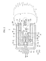
- FIG. 2 is a sectional view of the combustion apparatus illustrated in FIG. 1 .
- FIG. 3 is a sectional view taken along line III-Iii in FIG. 2 .
- a combustion apparatus 1 includes a modifying part 100 for modifying hydrocarbon-based fuel into a high temperature modified gas including hydrogen and a supply part 200 jetting fuel and air to an outlet 101 of the combustion apparatus 1.
- Hydrogen included in the modified gas has fast combustion speed and fast diffusion speed.
- the high temperature modified gas and hydrogen supplied from the modifying part 100 form a flame F at a position distant from the outlet 101 of the combustion apparatus 1 and prevents the flame F from being blown off.
- the modified gas and hydrogen may stabilize the flame F at a position distant from the outlet 101 of the combustion apparatus 1.
- the modifying part 100 is provided in the center of the combustion apparatus 1 and configured to make supplied fuel react according to a partial oxidation condition to modify it into a gas including high temperature hydrogen and discharge the hydrogen and the modified gas to the outlet 101.
- the modified gas discharged from the modifying part 100 is jetted to a front side (the flame F) from the outlet 101 to push the flame F based on the combustion of the fuel supplied from the supply part 200 and air to stably maintain the flame F at a position distant from the outlet 101 by a pre-set distance L.
- the modifying part 100 is integrally provided in the combustion apparatus 1, so it can stably supply hydrogen toward the air and fuel supplied from the supply part 200 to the outlet 101.
- the modifying part 100 can supply hydrogen by a simple configuration, and thus, namely, an additional device for supplying hydrogen is not required.
- the supply part 200 is provided at an outer side of the outlet 101 and configured to jet fuel and air to an outer side of the discharged modified gas to form the flame F.
- the supply part 200 according to the present embodiment is formed to have a structure for accommodating the modifying part 100. The fuel and air supplied from the supply part 200 is pushed by a pre-set distance L from the outlet 101 by the modified gas supplied from the modifying part 100.
- the fuel and air supplied from the supply part 200 are burnt at a position distant from the outlet 101 by the distance L, rather than being blown off, thus stably maintaining the flame F.
- the distance L set between the outlet 101 and the flame F secures a longer period of time for mixing fuel and air supplied from the supply part 200.
- the fuel and air in a state of having left the outlet 101 may be further uniformly mixed while proceeding by the distance L.
- the combustion apparatus 1 can drastically generation of NOx by using the fast combustion and spreading performance of the high temperature modified gas and hydrogen generated in the modifying part 100 when fuel is burnt.
- O 2 /C ratio may range from 0.7 to 1.9.
- the combustion apparatus 1 will be described in detail.
- the modifying part 100 includes a first housing 10 supplying air and electrically earthed, and an electrode E separately installed at the center within the housing 10 to supply fuel and receiving a voltage HV applied thereto.
- the expanded region 112 is formed to be expanded greater than a diameter of the discharge region 111 at one side of the discharge region 111, and stabilizes gas discharged after being reacted under the partial oxidation condition and discharges the stabilized gas. Namely, the modified gas reacted under the partial oxidation condition is re-circulated in the large space of the expanded region 112 so as to be stabilized.
- the supply part 200 includes a second housing 20 separately disposed on an outer circumference of the first housing 10 and a third housing 30 separately disposed on an outer circumference of the second housing 20.
- the first housing 10 is accommodated in the second housing
- the second housing 20 is accommodated in the third housing 30 by stages.
- the first, second, and third housings 10, 20, and 30 may form a concentric circular structure.
- a fuel passage P1 is formed between the first housing 10 and the second housing 20, and an air passage P2 is formed between the second housing 20 and the third housing 30.
- the fuel passage P1 and the air passage P2 supply fuel and air supplied to one side thereof to the modifying part 100 and the supply part 200.
- the air passage P2 is connected to the discharge region 111 of the modifying part 100 across the fuel passage P1 by a passage connection member 22 connected to the first housing 10 by passing through the second housing 20.
- the air passage P2 supplies air to the discharge region 111.
- the air passage P2 supplies air between end portions E2 and E3 of the second and third housings 20 and 30 of the supply part 200.
- the second housing 20 includes a side wall 21 formed at one side of the fuel passage P1, and the first housing 10 may be connected to the side wall 21 of the second housing 20 through various methods such as screw connection, welding, or the like.
- the first housing 10 further includes a coupling portion 11 protruded toward the side wall 21 of the second housing 20. Namely, a male screw of the coupling portion 11 is screw-connected to a female screw of the side wall 21.
- the fuel passage P1 set between the first and second housings 10 and 20 includes an inflow side P11 formed in the center at one side of the first housing 10 and a supply side P12 connected to an outer circumference of the first housing 10.
- the coupling portion 11 of the first housing 10 includes a through hole 12 connecting the inflow side P11 and the supply side P12 of the fuel passage P1. As soon as air introduced to the inflow side P11 is supplied to the discharge region 111, it is supplied to the supply side P12 through the through hole 12 of the coupling portion 11.
- the first housing 10 includes a flange 13 formed on an end portion E1 set in one side of the second housing 20 in a length direction (in a horizontal direction in FIG. 2 ).
- the flange 13 is formed to be protruded to the outside in a diameter direction of the second housing 20 and forms a space C with the end portion E2 of the second housing 20.
- the space C allow the supply side P12 of the fuel passage P1 to be open toward the outer side in a diameter direction of the second housing 20, so that supplied fuel can be supplied toward the outer side of the second housing 20.
- end portion E2 of the second housing 20 and the end portion E3 of the third housing 30 are disposed in the same straight line in the diameter direction, allowing air supplied through the air passage P2 to be mixed with fuel supplied between the both end portions E2 and E3.
- fuel supplied through the fuel passage P1 is supplied to the end of the air passage P2 through the space C so as to be mixed with air supplied through the air passage P2, and discharged to a front side of the outlet 101 in the combustion apparatus 1 to form the flame F.
- the size of the space C may be adjusted according to a range in which the coupling portion 11 of the first housing 10 is fastened to the side wall 21 of the second housing 20.
- a mixture ratio of air and fuel may be set by controlling supply of fuel through the fuel passage P1 with respect to supply of air through the air passage P2 according to a size of the space C.
- the first housing 10 includes an inner member 14 and an outer member 15 coupled to partially overlap with each other in a length direction.
- the inner member 14 includes an air nozzle 16 jetting air toward the electrode E of the discharge region 111.
- a plurality of air nozzles 16 are disposed to be spaced apart from the inner member 14 in a circumferential direction, and have an angle ( ⁇ ) sloped with respect to a diameter direction of the inner member 14 (See FIG. 3 ).
- ⁇ angle
- air supplied to the air nozzle 16 is supplied while being rotated in the circumferential direction between the electrode E and the first housing 10 and in the gap G.
- the outer member 15 includes a chamber 17 coupled to an outer circumference of the inner member 14 and accommodating air upon receiving it from the air nozzle 16.
- the chamber 17 makes amounts of air jet through the plurality of air nozzles 16 uniform by uniformly maintaining pressure of supplied air.
- the electrode E forming the discharge region 111 together with the inner member 14 includes a fuel nozzle 26 jetting fuel.
- the fuel nozzle 26 is connected to the inflow side P11 of the fuel passage P1 and jets supplied fuel to the inner wall of the inner member 14 in the vicinity of the gap G.
- the fuel jetted to the gap G of the discharge region 111 is mixed with air rotated upon being jetted through the air nozzle 16, and reacts under a partial oxidation condition, while generating a rotating arc by a voltage HV set between the electrode E and the inner member 14. Namely, fuel is modified into a high temperature gas including hydrogen.
- the hydrogen and the modified gas modified in the discharge region 111 is recirculated in the expanded region 112 so as to be stabilized and discharged to the outlet 101.
- the discharged hydrogen and modified gas act as pushing force in the distance L within a pre-set range in front of the outlet 101 to thrust fuel and air supplied to the supply part 200 out of the range of the distance L.
- the fuel and air supplied to the supply part 200 reaches outside of the range of the distance L through the outside of the region of the hydrogen and modified gas.
- the modified gas is maintained to have a high temperature state and hydrogen has a fast combustion and spreading speed.
- the fuel and air supplied to the supply part 200 is implemented for lean combustion outside of the range of the distance L, stably maintaining the flame F.
- the fuel and air supplied to the supply part 20 are mixed to have a further uniform state for an additional mixture time, implementing lean combustion.
- generation of NOx can be reduced.
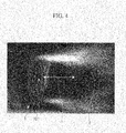
- FIG. 4 is a photograph showing a state of a flame when fuel is burnt by the combustion apparatus 1 of FIG. 1
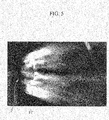
- FIG. 5 is a photograph showing a state of a flame when fuel is burnt by the related art combustion apparatus.
- the related art combustion apparatus 2 approaches the outlet to form a flame F2.
- the combustion apparatus 1 according to an embodiment of the present invention stabilizes the flame F at a position distant from the outlet 101 by the distance L. It can be seen that the flame F is not formed in the central portion of the outlet 101.
- FIG. 6 is a sectional view of a combustion apparatus according to a second embodiment of the present invention.
- a supply part 300 is formed to jet fuel and air in a direction parallel to the discharge direction of the modified gas at an outer side of the modified gas including hydrogen discharged from the modifying part 100.
- an end portion E21 of the first housing 10 includes a flange 23 disposed at an inner side of an end portion E22 of the second hosing 20 and protruded inwardly in a diameter direction of the first housing 10.
- the flange 23 is formed to narrow the outlet 102 in the discharge region 111 to thus lower or adjust a speed of the modified gas including hydrogen sprut through the outlet 102.
- An end portion E23 of the third housing 30 is disposed to be parallel in the outlet 102 together with the end portion E22 of the second housing 20.
- a first swirler S1 may is provided between the end portions E21 and E22 of the first and second housings 10 and 20 forming the fuel passage P1 in order to swirl discharged fuel.
- a second swirler S2 is provided between the end portions E22 and E23 of the second and third housings 20 and 30 forming the air passage P2 in order to swirl discharged air.
- fuel discharged between the end portions E21 and E22 of the first and second housings 10 and 20 and air discharged between the end portions E22 and E23 of the second and third housings 20 and 30 are swirled to be mixed by the first and second swirlers S1 and S2, so as to be discharged while being swirled in a direction parallel to the discharge direction of the modified gas.
- the fuel and air mixed by the first and second swirlers S1 and S2 may form the flame F, without being blown out, at a position distant from the outlet 102 by the distance L according to the discharge speed of the modified gas.
Landscapes
- Engineering & Computer Science (AREA)
- Chemical & Material Sciences (AREA)
- Combustion & Propulsion (AREA)
- Mechanical Engineering (AREA)
- General Engineering & Computer Science (AREA)
- Hydrogen, Water And Hydrids (AREA)
- Pre-Mixing And Non-Premixing Gas Burner (AREA)
Abstract
Description
- The present invention relates to a combustion apparatus for reducing generation of NOx by forming flame at a position distant from an outlet by jetting a gas including high temperature hydrogen generated by modifying hydrocarbon fuel.
- A general combustion apparatus is configured to make supplied fuel and air meet in the interior or exterior to form a diffusion flame. Here, a generation rate of NOx (or generation of NOx) may differ according to a mixture degree and a mixture speed of fuel and air.
- In order to reduce generation of NOx, a combustion apparatus for jetting air or fuel by multiple stages or performing fuel-rich combustion and lean combustion by several stages has been developed. However, multi-staged combustion lengthens flame and makes a structure of a combustion apparatus complicated.
- In an effort to solve the problem, a combustion apparatus capable of reducing generation of NOx by mixing fuel and air rapidly has been developed. In this case, the combustion apparatus requires an ignitor (i.e., a lighter or a firer) for igniting flame, and a pilot flame for settling and stabilizing in a combustion apparatus should be formed in an outlet of the combustion apparatus. Namely, without the pilot flame, flame is blown out from the outlet of the combustion apparatus.
- The above information disclosed in this Background section is only for enhancement of understanding of the background of the invention and therefore it may contain information that does not form the prior art that is already known in this country to a person of ordinary skill in the art.
- The present invention has been made in an effort to provide a combustion apparatus having advantages of reducing generation of NOx by securing more time for mixing fuel and air and uniformly mixing fuel and air.
- The present invention has also been made in an effort to provide a combustion apparatus having advantages of forming a flame at a position distant from an outlet, without being blown out, by modifying fuel and supplying a modified gas including hydrogen from the center of the outlet.
- An exemplary embodiment of the present invention provides a combustion apparatus including: a modifying part configured in the center to modify supplied hydrocarbon-based fuel and air and discharge high temperature modified gas including hydrogen to an outlet; and a supply part configured at an outer side of the outlet to jet fuel and air to one side of the modified gas discharged from the modifying part to form a flame at a position spaced apart by a pre-set distance from the outlet.
- An equivalence ratio of hydrocarbon-based fuel in the mixture of fuel and air supplied to the modifying part may range from a stoichiometric ratio of partial oxidation to a stoichiometric ratio of combustion.
- The modifying part may include a first housing electrically earthed; and an electrode separately installed in the center within the first housing and receiving a voltage applied thereto.
- The first housing may include: a discharge region forming a discharge gap with the electrode therebetween to allow fuel and air to react under a partial oxidation condition; and an expanded region expanded from the discharge region to stabilize gas discharged after being reacted in the discharge region.
- The supply part may be formed to jet fuel and air to an outer side of the modified gas discharged from the modifying part.
- The supply part may include a second housing separately disposed on an outer circumference of the first housing and a third housing separately disposed on an outer circumference of the second housing, and may further include a fuel passage formed between the first housing and the second housing and an air passage formed between the second housing and the third housing.
- The air passage may be connected to the discharge region across the fuel passage by a passage connection member connecting the second housing and the first housing.
- The second housing may have a side wall formed at one side of the fuel passage, and the first housing may be connected to the side wall through a method such as screw-connection, welding, or the like.
- The first housing may further include a coupling portion protruded toward the side wall of the second housing, the fuel passage may include an inflow side formed at the center of one side of the first housing and a supply side connected to the outer circumference of the first housing, and the coupling portion may include a through hole connecting the inflow side and the supply side.
- An end portion of the first housing includes a flange formed to be protruded to an outer side in a diameter direction of the second housing such that a space is formed with an end portion of the second housing in a length direction of the second housing in the opposite side of the side wall of the second housing, and the space set between the flange and the end portion of the second housing may allow the supply side of the fuel passage to open to the outside in the diameter direction of the second housing.
- The end portion of the second housing and an end portion of the third housing may be disposed in the same line in the diameter direction.
- The first housing may include an inner member forming an air nozzle jetting air toward the electrode, and an outer member coupled to an outer circumference of the inner member and accommodating air to be jetted through the air nozzle upon receiving it.
- A plurality of air nozzles may be disposed to be spaced apart from each other in a circumferential direction in the inner member, and may have an angle sloped with respect to a diameter direction of the inner member.
- The supply part may be formed to jet fuel and air in a direction parallel to the direction in which the modified gas is discharged from an outer side of the modified gas discharged from the modifying part.
- The supply part may include a second housing separately disposed on an outer circumference of the first housing and a third housing separately disposed on an outer circumference of the second housing, and may further include a fuel passage formed between the first housing and the second housing and an air passage formed between the second housing and the third housing, and an end portion of the first housing may include a flange disposed at an inner side of an end portion of the second housing and protruded inwardly in a diameter direction of the first housing.
- The end portion of the first housing and the end portion of the second housing may be formed to be parallel to each other, and a first swirler may be installed between the end portion of the first housing and the end portion of the second housing and a second swirler may be installed between the end portion of the second housing and the end portion of the third housing.
- According to embodiments of the present invention, the modifying part modifies fuel to discharge a modified gas including hydrogen and supplies fuel and air to an outer side of an outlet to the supply part, and thus, a flame can be stably formed at a position spaced apart by a pre-set distance from the outlet.
- Thus, a time for mixing fuel supplied from the supply part and air can be further secured by a time corresponding to the distance between the outlet of the combustion apparatus and the flame. Since the mixture time is lengthened, fuel and air can be more uniformly mixed, and thus, generation of NOx can be reduced.
-
-
FIG. 1 is a partial sectional perspective view of a combustion apparatus according to a first embodiment of the present invention. -
FIG. 2 is a sectional view of the combustion apparatus illustrated inFIG. 1 . -
FIG. 3 is a sectional view taken along line III-Iii inFIG. 2 . -
FIG. 4 is a photograph showing a state of a flame when fuel is burnt by the combustion apparatus ofFIG. 1 . -
FIG. 5 is a photograph showing a state of a flame when fuel is burnt by the related art combustion apparatus. -
FIG. 6 is a sectional view of a combustion apparatus according to a second embodiment of the present invention. - Hereinafter, the present invention will be described more fully hereinafter with reference to the accompanying drawings, in which exemplary embodiments of the invention are shown. As those skilled in the art would realize, the described embodiments may be modified in various different ways, all without departing from the spirit or scope of the present invention. The drawings and description are to be regarded as illustrative in nature and not restrictive. Like reference numerals designate like elements throughout the specification.
-
FIG. 1 is a partial sectional perspective view of a combustion apparatus according to a first embodiment of the present invention.FIG. 2 is a sectional view of the combustion apparatus illustrated inFIG. 1 .FIG. 3 is a sectional view taken along line III-Iii inFIG. 2 . - Referring to
FIGS. 1 to 3 , acombustion apparatus 1 according to a first embodiment of the present invention includes a modifyingpart 100 for modifying hydrocarbon-based fuel into a high temperature modified gas including hydrogen and asupply part 200 jetting fuel and air to anoutlet 101 of thecombustion apparatus 1. Hydrogen included in the modified gas has fast combustion speed and fast diffusion speed. Thus, the high temperature modified gas and hydrogen supplied from the modifyingpart 100 form a flame F at a position distant from theoutlet 101 of thecombustion apparatus 1 and prevents the flame F from being blown off. Namely, the modified gas and hydrogen may stabilize the flame F at a position distant from theoutlet 101 of thecombustion apparatus 1. - To this end, the modifying
part 100 is provided in the center of thecombustion apparatus 1 and configured to make supplied fuel react according to a partial oxidation condition to modify it into a gas including high temperature hydrogen and discharge the hydrogen and the modified gas to theoutlet 101. - The modified gas discharged from the modifying
part 100 is jetted to a front side (the flame F) from theoutlet 101 to push the flame F based on the combustion of the fuel supplied from thesupply part 200 and air to stably maintain the flame F at a position distant from theoutlet 101 by a pre-set distance L. - In the present embodiment, the modifying
part 100 is integrally provided in thecombustion apparatus 1, so it can stably supply hydrogen toward the air and fuel supplied from thesupply part 200 to theoutlet 101. Thus, the modifyingpart 100 can supply hydrogen by a simple configuration, and thus, namely, an additional device for supplying hydrogen is not required. - The
supply part 200 is provided at an outer side of theoutlet 101 and configured to jet fuel and air to an outer side of the discharged modified gas to form the flame F. Thesupply part 200 according to the present embodiment is formed to have a structure for accommodating the modifyingpart 100. The fuel and air supplied from thesupply part 200 is pushed by a pre-set distance L from theoutlet 101 by the modified gas supplied from the modifyingpart 100. - However, due to fast combustion and spreading speed of the high temperature modified gas and hydrogen supplied from the modifying
part 100, the fuel and air supplied from thesupply part 200 are burnt at a position distant from theoutlet 101 by the distance L, rather than being blown off, thus stably maintaining the flame F. - The distance L set between the
outlet 101 and the flame F secures a longer period of time for mixing fuel and air supplied from thesupply part 200. Thus, the fuel and air in a state of having left theoutlet 101 may be further uniformly mixed while proceeding by the distance L. - In this manner, the
combustion apparatus 1 according to the present embodiment can drastically generation of NOx by using the fast combustion and spreading performance of the high temperature modified gas and hydrogen generated in the modifyingpart 100 when fuel is burnt. - When a mixture ratio of the fuel and air in the modifying
part 100 is excessively rich, a partial oxidation reaction does not take place and hydrogen is not generated. Conversely, when the mixture ratio of the fuel and air in the modifyingpart 100 is overly close to a combustion ratio, the flame is maintained only within the modifyingpart 100 and hydrogen is not generated. - When hydrogen is not generated in the modifying
part 100, flame formed according to combustion of fuel and air supplied to thesupply part 200 is blown out in theoutlet 101 of thecombustion apparatus 1. Thus, a mixture of fuel and air is required to have an appropriate equivalence ratio. - For example, since a stoichiometric ratio of partial oxidation in a hydrocarbon-based fuel is 0.5 and a stoichiometric ratio of combustion is 2.0. Thus, in case of LNG having methane as a main ingredient in a mixture of fuel and air in the modifying
part 100, O2/C ratio may range from 0.7 to 1.9. - The
combustion apparatus 1 will be described in detail. The modifyingpart 100 includes afirst housing 10 supplying air and electrically earthed, and an electrode E separately installed at the center within thehousing 10 to supply fuel and receiving a voltage HV applied thereto. - When the voltage HV is applied to the electrode E, plasma discharge occurs in the fuel and air mixed between the electrode E and the
first housing 10. In this case, the fuel is partially oxidized to form a high temperature modified gaseous state including hydrogen. - The
first housing 10 includes adischarge region 111 and an expandedregion 112 set according to a direction in which a gas modified as fuel and air are introduced is discharged. Thedischarge region 111 has a discharge gap G formed between thefirst housing 10 and the electrode E, and plasma discharge occurs in the discharge gap G to allow supplied fuel and air to react under a partial oxidation condition so as to be modified. - The expanded
region 112 is formed to be expanded greater than a diameter of thedischarge region 111 at one side of thedischarge region 111, and stabilizes gas discharged after being reacted under the partial oxidation condition and discharges the stabilized gas. Namely, the modified gas reacted under the partial oxidation condition is re-circulated in the large space of the expandedregion 112 so as to be stabilized. - The
supply part 200 includes asecond housing 20 separately disposed on an outer circumference of thefirst housing 10 and athird housing 30 separately disposed on an outer circumference of thesecond housing 20. In this case, thefirst housing 10 is accommodated in the second housing, and thesecond housing 20 is accommodated in thethird housing 30 by stages. For example, the first, second, andthird housings - A fuel passage P1 is formed between the
first housing 10 and thesecond housing 20, and an air passage P2 is formed between thesecond housing 20 and thethird housing 30. The fuel passage P1 and the air passage P2 supply fuel and air supplied to one side thereof to the modifyingpart 100 and thesupply part 200. - For example, the air passage P2 is connected to the
discharge region 111 of the modifyingpart 100 across the fuel passage P1 by apassage connection member 22 connected to thefirst housing 10 by passing through thesecond housing 20. The air passage P2 supplies air to thedischarge region 111. Also, the air passage P2 supplies air between end portions E2 and E3 of the second andthird housings supply part 200. - For example, the
second housing 20 includes aside wall 21 formed at one side of the fuel passage P1, and thefirst housing 10 may be connected to theside wall 21 of thesecond housing 20 through various methods such as screw connection, welding, or the like. For the screw connection, thefirst housing 10 further includes acoupling portion 11 protruded toward theside wall 21 of thesecond housing 20. Namely, a male screw of thecoupling portion 11 is screw-connected to a female screw of theside wall 21. - Here, the fuel passage P1 set between the first and
second housings first housing 10 and a supply side P12 connected to an outer circumference of thefirst housing 10. - The
coupling portion 11 of thefirst housing 10 includes a throughhole 12 connecting the inflow side P11 and the supply side P12 of the fuel passage P1. As soon as air introduced to the inflow side P11 is supplied to thedischarge region 111, it is supplied to the supply side P12 through the throughhole 12 of thecoupling portion 11. - In the opposite side of the
side wall 21 of thesecond housing 20, thefirst housing 10, thefirst housing 10 includes aflange 13 formed on an end portion E1 set in one side of thesecond housing 20 in a length direction (in a horizontal direction inFIG. 2 ). - The
flange 13 is formed to be protruded to the outside in a diameter direction of thesecond housing 20 and forms a space C with the end portion E2 of thesecond housing 20. The space C allow the supply side P12 of the fuel passage P1 to be open toward the outer side in a diameter direction of thesecond housing 20, so that supplied fuel can be supplied toward the outer side of thesecond housing 20. - Here, the end portion E2 of the
second housing 20 and the end portion E3 of thethird housing 30 are disposed in the same straight line in the diameter direction, allowing air supplied through the air passage P2 to be mixed with fuel supplied between the both end portions E2 and E3. - Namely, fuel supplied through the fuel passage P1 is supplied to the end of the air passage P2 through the space C so as to be mixed with air supplied through the air passage P2, and discharged to a front side of the
outlet 101 in thecombustion apparatus 1 to form the flame F. - The size of the space C may be adjusted according to a range in which the
coupling portion 11 of thefirst housing 10 is fastened to theside wall 21 of thesecond housing 20. A mixture ratio of air and fuel may be set by controlling supply of fuel through the fuel passage P1 with respect to supply of air through the air passage P2 according to a size of the space C. - Also, the
first housing 10 includes aninner member 14 and anouter member 15 coupled to partially overlap with each other in a length direction. Theinner member 14 includes anair nozzle 16 jetting air toward the electrode E of thedischarge region 111. - A plurality of
air nozzles 16 are disposed to be spaced apart from theinner member 14 in a circumferential direction, and have an angle (⊝) sloped with respect to a diameter direction of the inner member 14 (SeeFIG. 3 ). Thus, air supplied to theair nozzle 16 is supplied while being rotated in the circumferential direction between the electrode E and thefirst housing 10 and in the gap G. - The
outer member 15 includes achamber 17 coupled to an outer circumference of theinner member 14 and accommodating air upon receiving it from theair nozzle 16. Thus, thechamber 17 makes amounts of air jet through the plurality ofair nozzles 16 uniform by uniformly maintaining pressure of supplied air. - Meanwhile, the electrode E forming the
discharge region 111 together with theinner member 14 includes afuel nozzle 26 jetting fuel. Thefuel nozzle 26 is connected to the inflow side P11 of the fuel passage P1 and jets supplied fuel to the inner wall of theinner member 14 in the vicinity of the gap G. - The fuel jetted to the gap G of the
discharge region 111 is mixed with air rotated upon being jetted through theair nozzle 16, and reacts under a partial oxidation condition, while generating a rotating arc by a voltage HV set between the electrode E and theinner member 14. Namely, fuel is modified into a high temperature gas including hydrogen. - The hydrogen and the modified gas modified in the
discharge region 111 is recirculated in the expandedregion 112 so as to be stabilized and discharged to theoutlet 101. The discharged hydrogen and modified gas act as pushing force in the distance L within a pre-set range in front of theoutlet 101 to thrust fuel and air supplied to thesupply part 200 out of the range of the distance L. - Thus, the fuel and air supplied to the
supply part 200 reaches outside of the range of the distance L through the outside of the region of the hydrogen and modified gas. At the same time, the modified gas is maintained to have a high temperature state and hydrogen has a fast combustion and spreading speed. Thus, the fuel and air supplied to thesupply part 200 is implemented for lean combustion outside of the range of the distance L, stably maintaining the flame F. - While proceeding by the distance L, the fuel and air supplied to the
supply part 20 are mixed to have a further uniform state for an additional mixture time, implementing lean combustion. Thus, when fuel is burnt, generation of NOx can be reduced. -
FIG. 4 is a photograph showing a state of a flame when fuel is burnt by thecombustion apparatus 1 ofFIG. 1 , andFIG. 5 is a photograph showing a state of a flame when fuel is burnt by the related art combustion apparatus. - Referring to
FIGS. 4 and5 , the relatedart combustion apparatus 2 approaches the outlet to form a flame F2. In comparison, thecombustion apparatus 1 according to an embodiment of the present invention stabilizes the flame F at a position distant from theoutlet 101 by the distance L. It can be seen that the flame F is not formed in the central portion of theoutlet 101. - Hereinafter, a second embodiment of the present invention will be described. A description of the same configuration as that of the first embodiment will be omitted and a different configuration from that of the first embodiment will be described.
-
FIG. 6 is a sectional view of a combustion apparatus according to a second embodiment of the present invention. Referring toFIG. 6 , in acombustion apparatus 3 according to the second embodiment of the present invention, asupply part 300 is formed to jet fuel and air in a direction parallel to the discharge direction of the modified gas at an outer side of the modified gas including hydrogen discharged from the modifyingpart 100. - For example, an end portion E21 of the
first housing 10 includes aflange 23 disposed at an inner side of an end portion E22 of thesecond hosing 20 and protruded inwardly in a diameter direction of thefirst housing 10. - The
flange 23 is formed to narrow theoutlet 102 in thedischarge region 111 to thus lower or adjust a speed of the modified gas including hydrogen sprut through theoutlet 102. - An end portion E23 of the
third housing 30 is disposed to be parallel in theoutlet 102 together with the end portion E22 of thesecond housing 20. A first swirler S1 may is provided between the end portions E21 and E22 of the first andsecond housings third housings - Thus, fuel discharged between the end portions E21 and E22 of the first and
second housings third housings - The fuel and air mixed by the first and second swirlers S1 and S2 may form the flame F, without being blown out, at a position distant from the
outlet 102 by the distance L according to the discharge speed of the modified gas. - While this invention has been described in connection with what is presently considered to be practical exemplary embodiments, it is to be understood that the invention is not limited to the disclosed embodiments, but, on the contrary, is intended to cover various modifications and equivalent arrangements included within the spirit and scope of the appended claims.
-
<Description of symbols> 10, 20, 30: first, second, and third housing 11: coupling portion 12: through hole 13, 23: flange 14: inner member 15: outer member 16: air nozzle 17: chamber 21: side wall 100: modifying part 101, 102: outlet 111: discharge region 112: expanded region 200: supply part C: interval E1, E2, E3, E21, E22, E23: end portion F: flame L: distance P1: fuel passage P11: inflow side P12: supply side P2: air passage 1, 2, 3: combustion apparatus
Claims (16)
- A combustion apparatus comprising:a modifying part configured in the center to modify supplied hydrocarbon-based fuel and air and discharge high temperature modified gas including hydrogen to an outlet; anda supply part configured at an outer side of the outlet to jet fuel and air to one side of the modified gas discharged from the modifying part to form a flame at a position spaced apart by a pre-set distance from the outlet.
- The combustion apparatus of claim 1, wherein an equivalence ratio of hydrocarbon-based fuel in the mixture of fuel and air supplied to the modifying part ranges from a stoichiometric ratio of partial oxidation to a stoichiometric ratio of combustion.
- The combustion apparatus of claim 1, wherein the modifying part comprises:a first housing electrically earthed; andan electrode separately installed in the center within the first housing and receiving a voltage applied thereto.
- The combustion apparatus of claim 3, wherein the first housing comprises:a discharge region forming a discharge gap with the electrode therebetween to allow fuel and air to react under a partial oxidation condition; andan expanded region expanded from the discharge region to stabilize gas discharged after being reacted in the discharge region.
- The combustion apparatus of claim 3 or claim 4, wherein the supply part is formed to jet fuel and air to an outer side of the modified gas discharged from the modifying part.
- The combustion apparatus of claim 5, wherein the supply part comprises
a second housing separately disposed on an outer circumference of the first housing; and
a third housing separately disposed on an outer circumference of the second housing, and
further comprises:a fuel passage formed between the first housing and the second housing; andan air passage formed between the second housing and the third housing. - The combustion apparatus of claim 6, wherein the air passage is connected to the discharge region across the fuel passage by a passage connection member connecting the second housing and the first housing.
- The combustion apparatus of claim 6, wherein the second housing has a side wall formed at one side of the fuel passage, and the first housing is connected to the side wall through a method such as screw-connection or welding.
- The combustion apparatus of claim 8, wherein the first housing further comprises a coupling portion protruded toward the side wall of the second housing,
the fuel passage comprises
an inflow side formed at the center of one side of the first housing and
a supply side connected to the outer circumference of the first housing, and
the coupling portion comiprises a through hole connecting the inflow side and the supply side. - The combustion apparatus of claim 9, wherein an end portion of the first housing includes a flange formed to be protruded to an outer side in a diameter direction of the second housing such that a space is formed with an end portion of the second housing in a length direction of the second housing in the opposite side of the side wall of the second housing, and
the space set between the flange and the end portion of the second housing allows the supply side of the fuel passage to open to the outside in the diameter direction of the second housing. - The combustion apparatus of claim 10, wherein the end portion of the second housing and an end portion of the third housing are disposed in the same line in the diameter direction.
- The combustion apparatus of claim 3, wherein the first housing comprises:an inner member forming an air nozzle jetting air toward the electrode; andan outer member coupled to an outer circumference of the inner member and accommodating air to be jetted through the air nozzle upon receiving it.
- The combustion apparatus of claim 12, wherein a plurality of air nozzles are disposed to be spaced apart from each other in a circumferential direction in the inner member, and have an angle sloped with respect to a diameter direction of the inner member.
- The combustion apparatus of claim 3 or claim 4, wherein the supply part is formed to jet fuel and air in a direction parallel to the direction in which the modified gas is discharged from an outer side of the modified gas discharged from the modifying part.
- The combustion apparatus of claim 12, wherein the supply part comprises:a second housing separately disposed on an outer circumference of the first housing anda third housing separately disposed on an outer circumference of the second housing, andfurther comprises:a fuel passage formed between the first housing and the second housing andan air passage formed between the second housing and the third housing, andan end portion of the first housing includes a flange disposed at an inner side of an end portion of the second housing and protruded inwardly in a diameter direction of the first housing.
- The combustion apparatus of claim 15, wherein
the end portion of the first housing and the end portion of the second housing are formed to be parallel to each other, and
a first swirler is installed between the end portion of the first housing and the end portion of the second housing and
a second swirler is installed between the end portion of the second housing and the end portion of the third housing.
Applications Claiming Priority (1)
| Application Number | Priority Date | Filing Date | Title |
|---|---|---|---|
| KR1020120086479A KR101284290B1 (en) | 2012-08-07 | 2012-08-07 | Combustion apparatus |
Publications (3)
| Publication Number | Publication Date |
|---|---|
| EP2696140A2 true EP2696140A2 (en) | 2014-02-12 |
| EP2696140A3 EP2696140A3 (en) | 2017-11-08 |
| EP2696140B1 EP2696140B1 (en) | 2020-09-02 |
Family
ID=47561108
Family Applications (1)
| Application Number | Title | Priority Date | Filing Date |
|---|---|---|---|
| EP12196852.3A Active EP2696140B1 (en) | 2012-08-07 | 2012-12-13 | Combustion apparatus with premixing element |
Country Status (6)
| Country | Link |
|---|---|
| US (1) | US20140045128A1 (en) |
| EP (1) | EP2696140B1 (en) |
| JP (1) | JP5435381B2 (en) |
| KR (1) | KR101284290B1 (en) |
| CN (1) | CN103574600B (en) |
| ES (1) | ES2830039T3 (en) |
Families Citing this family (15)
| Publication number | Priority date | Publication date | Assignee | Title |
|---|---|---|---|---|
| KR101607641B1 (en) | 2014-07-11 | 2016-03-30 | 한국기계연구원 | Burn-wet type scrubber |
| KR101672900B1 (en) * | 2015-06-15 | 2016-11-04 | 한국기계연구원 | Ammonia transformming device and urea scr system using of the same |
| CN105020743B (en) * | 2015-07-15 | 2017-10-03 | 哈尔滨工程大学 | A kind of fuel autoxidation cracks axially staged combustion chamber |
| FR3047277B1 (en) * | 2016-01-29 | 2019-12-20 | Arianegroup Sas | INJECTION ELEMENT PROVIDED WITH AN IGNITION DEVICE |
| US20170254264A1 (en) * | 2016-03-03 | 2017-09-07 | Technische Universität Berlin | Swirl-stabilised burner having an inertisation front and related methods |
| CN105783031B (en) * | 2016-04-18 | 2018-07-10 | 中国科学院工程热物理研究所 | A kind of integrated plasma excitation device, nozzle array and burner |
| CN107218623B (en) * | 2017-05-25 | 2019-08-09 | 航天神洁(北京)科技发展有限公司 | A sliding arc combustion-supporting device for generating atmospheric pressure non-equilibrium plasma |
| CN107525071B (en) * | 2017-08-03 | 2019-07-05 | 华中科技大学 | One kind plus water plasmas combustion system |
| KR102027497B1 (en) * | 2018-05-25 | 2019-10-01 | 한국기계연구원 | Plasma igniter for accelerating vaporization of fuel |
| CN112654818B (en) | 2018-06-28 | 2023-10-20 | 克利尔赛科技公司 | Variable component gas mixture sensor |
| KR102564961B1 (en) | 2021-09-09 | 2023-08-07 | 김정길 | Combustion apparatus |
| CN115175429A (en) * | 2022-07-18 | 2022-10-11 | 福建省万旗科技陶瓷有限公司 | Plasma generator for workpiece sintering and use method |
| KR102539129B1 (en) | 2023-02-16 | 2023-06-01 | 김정길 | Solid Fuel Combustion Device |
| KR102661800B1 (en) | 2023-11-15 | 2024-04-26 | 김정길 | Solid Fuel Combustion Device |
| CN121531541B (en) * | 2026-01-13 | 2026-04-03 | 离享未来(德州)等离子科技有限公司 | Plasma generator and chinese-medicinal material deinsectization device thereof |
Family Cites Families (14)
| Publication number | Priority date | Publication date | Assignee | Title |
|---|---|---|---|---|
| JP3014166B2 (en) * | 1991-05-30 | 2000-02-28 | オリンピア工業株式会社 | Gas burner |
| CN1099543C (en) * | 1996-03-22 | 2003-01-22 | 丰田自动车株式会社 | Low NOx burner |
| US6453660B1 (en) * | 2001-01-18 | 2002-09-24 | General Electric Company | Combustor mixer having plasma generating nozzle |
| FR2859272B1 (en) * | 2003-09-02 | 2005-10-14 | Snecma Moteurs | AIR / FUEL INJECTION SYSTEM IN A TURBOMACHINE COMBUSTION CHAMBER HAVING MEANS FOR GENERATING COLD PLASMA |
| JP4340873B2 (en) * | 2004-01-06 | 2009-10-07 | 株式会社ノーリツ | Combustion device |
| JP4421620B2 (en) * | 2007-02-15 | 2010-02-24 | 川崎重工業株式会社 | Gas turbine engine combustor |
| WO2009009948A1 (en) | 2007-07-19 | 2009-01-22 | Yantai Longyuan Power Technology Co., Ltd. | A burner ignited by plasma |
| US8257455B2 (en) * | 2007-07-30 | 2012-09-04 | Korea Institute Of Machinery & Materials | Plasma burner and diesel particulate filter trap |
| FR2919672B1 (en) * | 2007-07-30 | 2014-02-14 | Snecma | FUEL INJECTOR IN A TURBOMACHINE COMBUSTION CHAMBER |
| KR100910875B1 (en) * | 2008-03-21 | 2009-08-06 | 한국기계연구원 | Plasma scrubber |
| CN201363728Y (en) * | 2009-03-06 | 2009-12-16 | 苏和 | Air jet flow self-preheating burner nozzle |
| KR101174091B1 (en) * | 2010-12-22 | 2012-08-14 | 한국기계연구원 | Combustion apparatus using plasma |
| KR101050511B1 (en) * | 2011-04-26 | 2011-07-20 | 한국기계연구원 | Multistage combustion device using plasma |
| US9200561B2 (en) * | 2012-11-12 | 2015-12-01 | Mcalister Technologies, Llc | Chemical fuel conditioning and activation |
-
2012
- 2012-08-07 KR KR1020120086479A patent/KR101284290B1/en active Active
- 2012-12-13 EP EP12196852.3A patent/EP2696140B1/en active Active
- 2012-12-13 ES ES12196852T patent/ES2830039T3/en active Active
- 2012-12-14 JP JP2012272938A patent/JP5435381B2/en active Active
- 2012-12-14 US US13/714,521 patent/US20140045128A1/en not_active Abandoned
- 2012-12-26 CN CN201210573140.9A patent/CN103574600B/en active Active
Non-Patent Citations (1)
| Title |
|---|
| None |
Also Published As
| Publication number | Publication date |
|---|---|
| ES2830039T3 (en) | 2021-06-02 |
| KR101284290B1 (en) | 2013-07-08 |
| EP2696140B1 (en) | 2020-09-02 |
| JP2014035182A (en) | 2014-02-24 |
| CN103574600A (en) | 2014-02-12 |
| US20140045128A1 (en) | 2014-02-13 |
| EP2696140A3 (en) | 2017-11-08 |
| CN103574600B (en) | 2016-03-09 |
| JP5435381B2 (en) | 2014-03-05 |
Similar Documents
| Publication | Publication Date | Title |
|---|---|---|
| EP2696140B1 (en) | Combustion apparatus with premixing element | |
| CN102384474B (en) | Gas turbine combustor | |
| EP1985926B1 (en) | Combustion equipment and combustion method | |
| EP2481986B1 (en) | Gas turbine combustor | |
| US9109553B2 (en) | Fuel injector | |
| CN105164471B (en) | poor azimuth flame burner | |
| WO2018003488A1 (en) | Gas turbine combustor | |
| CN101446419A (en) | Burner tip, burner and improvement method of burner | |
| US20230304666A1 (en) | Dual fuel gas turbine engine pilot nozzles | |
| US20180372319A1 (en) | Fuel injection device | |
| KR101816490B1 (en) | Combustion apparatus | |
| KR101050511B1 (en) | Multistage combustion device using plasma | |
| US20180216828A1 (en) | A premixed dual fuel burner with a tapering injection component for main liquid fuel | |
| EP3336432B1 (en) | Staged radial air swirler with radial liquid fuel distributor | |
| KR101238301B1 (en) | LOW NOx OXYGEN BUNER WITH 2 STAGE PREMIXING CYLINDRICAL CHAMBER FLUE GAS RECIRCULATION | |
| CN105570930B (en) | Combustor arrangement for a gas turbine | |
| JP4977522B2 (en) | Gas turbine combustor | |
| EP3339738B1 (en) | Turbine including fuel gas recirculation combustor | |
| JP6929063B2 (en) | Type 2 fuel burner | |
| KR20240133991A (en) | Equipment including premix burner | |
| US11448175B1 (en) | Fuel nozzle | |
| EP4345373A1 (en) | Fuel-air mixing and flame stabilization device for a low emission burner with internal flue gas recirculation | |
| KR102829837B1 (en) | Nozzle for ammonia combustion, pilot burner for ammonia fuel including the same and ammonia combustor including the same | |
| KR101729617B1 (en) | Subminiature premixed torch ignitor for a gas turbine engine | |
| JP4480440B2 (en) | Combustion device and gas turbine engine |
Legal Events
| Date | Code | Title | Description |
|---|---|---|---|
| AK | Designated contracting states |
Kind code of ref document: A2 Designated state(s): AL AT BE BG CH CY CZ DE DK EE ES FI FR GB GR HR HU IE IS IT LI LT LU LV MC MK MT NL NO PL PT RO RS SE SI SK SM TR |
|
| AX | Request for extension of the european patent |
Extension state: BA ME |
|
| PUAI | Public reference made under article 153(3) epc to a published international application that has entered the european phase |
Free format text: ORIGINAL CODE: 0009012 |
|
| PUAL | Search report despatched |
Free format text: ORIGINAL CODE: 0009013 |
|
| RIC1 | Information provided on ipc code assigned before grant |
Ipc: F23D 14/64 20060101AFI20170928BHEP Ipc: F23D 14/68 20060101ALI20170928BHEP Ipc: F23D 14/84 20060101ALI20170928BHEP Ipc: F23C 99/00 20060101ALI20170928BHEP Ipc: F23D 14/22 20060101ALI20170928BHEP Ipc: F23D 14/70 20060101ALI20170928BHEP |
|
| AK | Designated contracting states |
Kind code of ref document: A3 Designated state(s): AL AT BE BG CH CY CZ DE DK EE ES FI FR GB GR HR HU IE IS IT LI LT LU LV MC MK MT NL NO PL PT RO RS SE SI SK SM TR |
|
| AX | Request for extension of the european patent |
Extension state: BA ME |
|
| STAA | Information on the status of an ep patent application or granted ep patent |
Free format text: STATUS: REQUEST FOR EXAMINATION WAS MADE |
|
| 17P | Request for examination filed |
Effective date: 20180504 |
|
| RBV | Designated contracting states (corrected) |
Designated state(s): AL AT BE BG CH CY CZ DE DK EE ES FI FR GB GR HR HU IE IS IT LI LT LU LV MC MK MT NL NO PL PT RO RS SE SI SK SM TR |
|
| GRAP | Despatch of communication of intention to grant a patent |
Free format text: ORIGINAL CODE: EPIDOSNIGR1 |
|
| STAA | Information on the status of an ep patent application or granted ep patent |
Free format text: STATUS: GRANT OF PATENT IS INTENDED |
|
| INTG | Intention to grant announced |
Effective date: 20200402 |
|
| GRAS | Grant fee paid |
Free format text: ORIGINAL CODE: EPIDOSNIGR3 |
|
| GRAA | (expected) grant |
Free format text: ORIGINAL CODE: 0009210 |
|
| STAA | Information on the status of an ep patent application or granted ep patent |
Free format text: STATUS: THE PATENT HAS BEEN GRANTED |
|
| AK | Designated contracting states |
Kind code of ref document: B1 Designated state(s): AL AT BE BG CH CY CZ DE DK EE ES FI FR GB GR HR HU IE IS IT LI LT LU LV MC MK MT NL NO PL PT RO RS SE SI SK SM TR |
|
| REG | Reference to a national code |
Ref country code: GB Ref legal event code: FG4D |
|
| REG | Reference to a national code |
Ref country code: AT Ref legal event code: REF Ref document number: 1309256 Country of ref document: AT Kind code of ref document: T Effective date: 20200915 Ref country code: CH Ref legal event code: EP |
|
| REG | Reference to a national code |
Ref country code: DE Ref legal event code: R096 Ref document number: 602012072077 Country of ref document: DE |
|
| REG | Reference to a national code |
Ref country code: IE Ref legal event code: FG4D |
|
| REG | Reference to a national code |
Ref country code: LT Ref legal event code: MG4D |
|
| PG25 | Lapsed in a contracting state [announced via postgrant information from national office to epo] |
Ref country code: FI Free format text: LAPSE BECAUSE OF FAILURE TO SUBMIT A TRANSLATION OF THE DESCRIPTION OR TO PAY THE FEE WITHIN THE PRESCRIBED TIME-LIMIT Effective date: 20200902 Ref country code: NO Free format text: LAPSE BECAUSE OF FAILURE TO SUBMIT A TRANSLATION OF THE DESCRIPTION OR TO PAY THE FEE WITHIN THE PRESCRIBED TIME-LIMIT Effective date: 20201202 Ref country code: GR Free format text: LAPSE BECAUSE OF FAILURE TO SUBMIT A TRANSLATION OF THE DESCRIPTION OR TO PAY THE FEE WITHIN THE PRESCRIBED TIME-LIMIT Effective date: 20201203 Ref country code: LT Free format text: LAPSE BECAUSE OF FAILURE TO SUBMIT A TRANSLATION OF THE DESCRIPTION OR TO PAY THE FEE WITHIN THE PRESCRIBED TIME-LIMIT Effective date: 20200902 Ref country code: BG Free format text: LAPSE BECAUSE OF FAILURE TO SUBMIT A TRANSLATION OF THE DESCRIPTION OR TO PAY THE FEE WITHIN THE PRESCRIBED TIME-LIMIT Effective date: 20201202 Ref country code: SE Free format text: LAPSE BECAUSE OF FAILURE TO SUBMIT A TRANSLATION OF THE DESCRIPTION OR TO PAY THE FEE WITHIN THE PRESCRIBED TIME-LIMIT Effective date: 20200902 Ref country code: HR Free format text: LAPSE BECAUSE OF FAILURE TO SUBMIT A TRANSLATION OF THE DESCRIPTION OR TO PAY THE FEE WITHIN THE PRESCRIBED TIME-LIMIT Effective date: 20200902 |
|
| REG | Reference to a national code |
Ref country code: NL Ref legal event code: MP Effective date: 20200902 |
|
| REG | Reference to a national code |
Ref country code: AT Ref legal event code: MK05 Ref document number: 1309256 Country of ref document: AT Kind code of ref document: T Effective date: 20200902 |
|
| PG25 | Lapsed in a contracting state [announced via postgrant information from national office to epo] |
Ref country code: PL Free format text: LAPSE BECAUSE OF FAILURE TO SUBMIT A TRANSLATION OF THE DESCRIPTION OR TO PAY THE FEE WITHIN THE PRESCRIBED TIME-LIMIT Effective date: 20200902 Ref country code: LV Free format text: LAPSE BECAUSE OF FAILURE TO SUBMIT A TRANSLATION OF THE DESCRIPTION OR TO PAY THE FEE WITHIN THE PRESCRIBED TIME-LIMIT Effective date: 20200902 Ref country code: RS Free format text: LAPSE BECAUSE OF FAILURE TO SUBMIT A TRANSLATION OF THE DESCRIPTION OR TO PAY THE FEE WITHIN THE PRESCRIBED TIME-LIMIT Effective date: 20200902 |
|
| PG25 | Lapsed in a contracting state [announced via postgrant information from national office to epo] |
Ref country code: NL Free format text: LAPSE BECAUSE OF FAILURE TO SUBMIT A TRANSLATION OF THE DESCRIPTION OR TO PAY THE FEE WITHIN THE PRESCRIBED TIME-LIMIT Effective date: 20200902 Ref country code: PT Free format text: LAPSE BECAUSE OF FAILURE TO SUBMIT A TRANSLATION OF THE DESCRIPTION OR TO PAY THE FEE WITHIN THE PRESCRIBED TIME-LIMIT Effective date: 20210104 Ref country code: RO Free format text: LAPSE BECAUSE OF FAILURE TO SUBMIT A TRANSLATION OF THE DESCRIPTION OR TO PAY THE FEE WITHIN THE PRESCRIBED TIME-LIMIT Effective date: 20200902 Ref country code: SM Free format text: LAPSE BECAUSE OF FAILURE TO SUBMIT A TRANSLATION OF THE DESCRIPTION OR TO PAY THE FEE WITHIN THE PRESCRIBED TIME-LIMIT Effective date: 20200902 Ref country code: EE Free format text: LAPSE BECAUSE OF FAILURE TO SUBMIT A TRANSLATION OF THE DESCRIPTION OR TO PAY THE FEE WITHIN THE PRESCRIBED TIME-LIMIT Effective date: 20200902 Ref country code: CZ Free format text: LAPSE BECAUSE OF FAILURE TO SUBMIT A TRANSLATION OF THE DESCRIPTION OR TO PAY THE FEE WITHIN THE PRESCRIBED TIME-LIMIT Effective date: 20200902 |
|
| PG25 | Lapsed in a contracting state [announced via postgrant information from national office to epo] |
Ref country code: IS Free format text: LAPSE BECAUSE OF FAILURE TO SUBMIT A TRANSLATION OF THE DESCRIPTION OR TO PAY THE FEE WITHIN THE PRESCRIBED TIME-LIMIT Effective date: 20210102 Ref country code: AL Free format text: LAPSE BECAUSE OF FAILURE TO SUBMIT A TRANSLATION OF THE DESCRIPTION OR TO PAY THE FEE WITHIN THE PRESCRIBED TIME-LIMIT Effective date: 20200902 Ref country code: AT Free format text: LAPSE BECAUSE OF FAILURE TO SUBMIT A TRANSLATION OF THE DESCRIPTION OR TO PAY THE FEE WITHIN THE PRESCRIBED TIME-LIMIT Effective date: 20200902 |
|
| REG | Reference to a national code |
Ref country code: ES Ref legal event code: FG2A Ref document number: 2830039 Country of ref document: ES Kind code of ref document: T3 Effective date: 20210602 |
|
| REG | Reference to a national code |
Ref country code: DE Ref legal event code: R097 Ref document number: 602012072077 Country of ref document: DE |
|
| PG25 | Lapsed in a contracting state [announced via postgrant information from national office to epo] |
Ref country code: SK Free format text: LAPSE BECAUSE OF FAILURE TO SUBMIT A TRANSLATION OF THE DESCRIPTION OR TO PAY THE FEE WITHIN THE PRESCRIBED TIME-LIMIT Effective date: 20200902 |
|
| PLBE | No opposition filed within time limit |
Free format text: ORIGINAL CODE: 0009261 |
|
| STAA | Information on the status of an ep patent application or granted ep patent |
Free format text: STATUS: NO OPPOSITION FILED WITHIN TIME LIMIT |
|
| REG | Reference to a national code |
Ref country code: CH Ref legal event code: PL |
|
| 26N | No opposition filed |
Effective date: 20210603 |
|
| PG25 | Lapsed in a contracting state [announced via postgrant information from national office to epo] |
Ref country code: MC Free format text: LAPSE BECAUSE OF FAILURE TO SUBMIT A TRANSLATION OF THE DESCRIPTION OR TO PAY THE FEE WITHIN THE PRESCRIBED TIME-LIMIT Effective date: 20200902 Ref country code: DK Free format text: LAPSE BECAUSE OF FAILURE TO SUBMIT A TRANSLATION OF THE DESCRIPTION OR TO PAY THE FEE WITHIN THE PRESCRIBED TIME-LIMIT Effective date: 20200902 Ref country code: SI Free format text: LAPSE BECAUSE OF FAILURE TO SUBMIT A TRANSLATION OF THE DESCRIPTION OR TO PAY THE FEE WITHIN THE PRESCRIBED TIME-LIMIT Effective date: 20200902 |
|
| REG | Reference to a national code |
Ref country code: BE Ref legal event code: MM Effective date: 20201231 |
|
| PG25 | Lapsed in a contracting state [announced via postgrant information from national office to epo] |
Ref country code: IE Free format text: LAPSE BECAUSE OF NON-PAYMENT OF DUE FEES Effective date: 20201213 Ref country code: IT Free format text: LAPSE BECAUSE OF FAILURE TO SUBMIT A TRANSLATION OF THE DESCRIPTION OR TO PAY THE FEE WITHIN THE PRESCRIBED TIME-LIMIT Effective date: 20200902 Ref country code: LU Free format text: LAPSE BECAUSE OF NON-PAYMENT OF DUE FEES Effective date: 20201213 |
|
| PG25 | Lapsed in a contracting state [announced via postgrant information from national office to epo] |
Ref country code: CH Free format text: LAPSE BECAUSE OF NON-PAYMENT OF DUE FEES Effective date: 20201231 Ref country code: LI Free format text: LAPSE BECAUSE OF NON-PAYMENT OF DUE FEES Effective date: 20201231 |
|
| PG25 | Lapsed in a contracting state [announced via postgrant information from national office to epo] |
Ref country code: TR Free format text: LAPSE BECAUSE OF FAILURE TO SUBMIT A TRANSLATION OF THE DESCRIPTION OR TO PAY THE FEE WITHIN THE PRESCRIBED TIME-LIMIT Effective date: 20200902 Ref country code: MT Free format text: LAPSE BECAUSE OF FAILURE TO SUBMIT A TRANSLATION OF THE DESCRIPTION OR TO PAY THE FEE WITHIN THE PRESCRIBED TIME-LIMIT Effective date: 20200902 Ref country code: CY Free format text: LAPSE BECAUSE OF FAILURE TO SUBMIT A TRANSLATION OF THE DESCRIPTION OR TO PAY THE FEE WITHIN THE PRESCRIBED TIME-LIMIT Effective date: 20200902 |
|
| PG25 | Lapsed in a contracting state [announced via postgrant information from national office to epo] |
Ref country code: MK Free format text: LAPSE BECAUSE OF FAILURE TO SUBMIT A TRANSLATION OF THE DESCRIPTION OR TO PAY THE FEE WITHIN THE PRESCRIBED TIME-LIMIT Effective date: 20200902 |
|
| PG25 | Lapsed in a contracting state [announced via postgrant information from national office to epo] |
Ref country code: BE Free format text: LAPSE BECAUSE OF NON-PAYMENT OF DUE FEES Effective date: 20201231 |
|
| PGFP | Annual fee paid to national office [announced via postgrant information from national office to epo] |
Ref country code: FR Payment date: 20250930 Year of fee payment: 14 |
|
| PGFP | Annual fee paid to national office [announced via postgrant information from national office to epo] |
Ref country code: DE Payment date: 20250930 Year of fee payment: 14 |
|
| PGFP | Annual fee paid to national office [announced via postgrant information from national office to epo] |
Ref country code: GB Payment date: 20251001 Year of fee payment: 14 |
|
| PGFP | Annual fee paid to national office [announced via postgrant information from national office to epo] |
Ref country code: ES Payment date: 20260119 Year of fee payment: 14 |