EP2696133A2 - Vehicular illumination lamp - Google Patents
Vehicular illumination lamp Download PDFInfo
- Publication number
- EP2696133A2 EP2696133A2 EP13179808.4A EP13179808A EP2696133A2 EP 2696133 A2 EP2696133 A2 EP 2696133A2 EP 13179808 A EP13179808 A EP 13179808A EP 2696133 A2 EP2696133 A2 EP 2696133A2
- Authority
- EP
- European Patent Office
- Prior art keywords
- translucent member
- front surface
- light
- incident
- reflected light
- Prior art date
- Legal status (The legal status is an assumption and is not a legal conclusion. Google has not performed a legal analysis and makes no representation as to the accuracy of the status listed.)
- Withdrawn
Links
- 238000005286 illumination Methods 0.000 title claims description 29
- 230000002093 peripheral effect Effects 0.000 abstract description 32
- 238000007740 vapor deposition Methods 0.000 description 13
- 230000003287 optical effect Effects 0.000 description 9
- 230000000694 effects Effects 0.000 description 3
- 239000000758 substrate Substances 0.000 description 3
- 230000008901 benefit Effects 0.000 description 2
- 238000000034 method Methods 0.000 description 2
- 229910052782 aluminium Inorganic materials 0.000 description 1
- XAGFODPZIPBFFR-UHFFFAOYSA-N aluminium Chemical compound [Al] XAGFODPZIPBFFR-UHFFFAOYSA-N 0.000 description 1
- 230000002708 enhancing effect Effects 0.000 description 1
- 238000004519 manufacturing process Methods 0.000 description 1
- 239000000463 material Substances 0.000 description 1
- 229910052751 metal Inorganic materials 0.000 description 1
- 239000002184 metal Substances 0.000 description 1
Images





Classifications
-
- F—MECHANICAL ENGINEERING; LIGHTING; HEATING; WEAPONS; BLASTING
- F21—LIGHTING
- F21S—NON-PORTABLE LIGHTING DEVICES; SYSTEMS THEREOF; VEHICLE LIGHTING DEVICES SPECIALLY ADAPTED FOR VEHICLE EXTERIORS
- F21S41/00—Illuminating devices specially adapted for vehicle exteriors, e.g. headlamps
- F21S41/10—Illuminating devices specially adapted for vehicle exteriors, e.g. headlamps characterised by the light source
- F21S41/14—Illuminating devices specially adapted for vehicle exteriors, e.g. headlamps characterised by the light source characterised by the type of light source
- F21S41/141—Light emitting diodes [LED]
- F21S41/143—Light emitting diodes [LED] the main emission direction of the LED being parallel to the optical axis of the illuminating device
-
- F—MECHANICAL ENGINEERING; LIGHTING; HEATING; WEAPONS; BLASTING
- F21—LIGHTING
- F21S—NON-PORTABLE LIGHTING DEVICES; SYSTEMS THEREOF; VEHICLE LIGHTING DEVICES SPECIALLY ADAPTED FOR VEHICLE EXTERIORS
- F21S41/00—Illuminating devices specially adapted for vehicle exteriors, e.g. headlamps
- F21S41/10—Illuminating devices specially adapted for vehicle exteriors, e.g. headlamps characterised by the light source
- F21S41/14—Illuminating devices specially adapted for vehicle exteriors, e.g. headlamps characterised by the light source characterised by the type of light source
- F21S41/141—Light emitting diodes [LED]
- F21S41/151—Light emitting diodes [LED] arranged in one or more lines
-
- F—MECHANICAL ENGINEERING; LIGHTING; HEATING; WEAPONS; BLASTING
- F21—LIGHTING
- F21S—NON-PORTABLE LIGHTING DEVICES; SYSTEMS THEREOF; VEHICLE LIGHTING DEVICES SPECIALLY ADAPTED FOR VEHICLE EXTERIORS
- F21S41/00—Illuminating devices specially adapted for vehicle exteriors, e.g. headlamps
- F21S41/20—Illuminating devices specially adapted for vehicle exteriors, e.g. headlamps characterised by refractors, transparent cover plates, light guides or filters
- F21S41/24—Light guides
-
- F—MECHANICAL ENGINEERING; LIGHTING; HEATING; WEAPONS; BLASTING
- F21—LIGHTING
- F21S—NON-PORTABLE LIGHTING DEVICES; SYSTEMS THEREOF; VEHICLE LIGHTING DEVICES SPECIALLY ADAPTED FOR VEHICLE EXTERIORS
- F21S41/00—Illuminating devices specially adapted for vehicle exteriors, e.g. headlamps
- F21S41/30—Illuminating devices specially adapted for vehicle exteriors, e.g. headlamps characterised by reflectors
- F21S41/32—Optical layout thereof
- F21S41/322—Optical layout thereof the reflector using total internal reflection
-
- F—MECHANICAL ENGINEERING; LIGHTING; HEATING; WEAPONS; BLASTING
- F21—LIGHTING
- F21S—NON-PORTABLE LIGHTING DEVICES; SYSTEMS THEREOF; VEHICLE LIGHTING DEVICES SPECIALLY ADAPTED FOR VEHICLE EXTERIORS
- F21S41/00—Illuminating devices specially adapted for vehicle exteriors, e.g. headlamps
- F21S41/30—Illuminating devices specially adapted for vehicle exteriors, e.g. headlamps characterised by reflectors
- F21S41/32—Optical layout thereof
- F21S41/33—Multi-surface reflectors, e.g. reflectors with facets or reflectors with portions of different curvature
- F21S41/331—Multi-surface reflectors, e.g. reflectors with facets or reflectors with portions of different curvature the reflector consisting of complete annular areas
-
- F—MECHANICAL ENGINEERING; LIGHTING; HEATING; WEAPONS; BLASTING
- F21—LIGHTING
- F21S—NON-PORTABLE LIGHTING DEVICES; SYSTEMS THEREOF; VEHICLE LIGHTING DEVICES SPECIALLY ADAPTED FOR VEHICLE EXTERIORS
- F21S43/00—Signalling devices specially adapted for vehicle exteriors, e.g. brake lamps, direction indicator lights or reversing lights
- F21S43/10—Signalling devices specially adapted for vehicle exteriors, e.g. brake lamps, direction indicator lights or reversing lights characterised by the light source
- F21S43/13—Signalling devices specially adapted for vehicle exteriors, e.g. brake lamps, direction indicator lights or reversing lights characterised by the light source characterised by the type of light source
- F21S43/14—Light emitting diodes [LED]
-
- F—MECHANICAL ENGINEERING; LIGHTING; HEATING; WEAPONS; BLASTING
- F21—LIGHTING
- F21S—NON-PORTABLE LIGHTING DEVICES; SYSTEMS THEREOF; VEHICLE LIGHTING DEVICES SPECIALLY ADAPTED FOR VEHICLE EXTERIORS
- F21S43/00—Signalling devices specially adapted for vehicle exteriors, e.g. brake lamps, direction indicator lights or reversing lights
- F21S43/20—Signalling devices specially adapted for vehicle exteriors, e.g. brake lamps, direction indicator lights or reversing lights characterised by refractors, transparent cover plates, light guides or filters
- F21S43/235—Light guides
-
- F—MECHANICAL ENGINEERING; LIGHTING; HEATING; WEAPONS; BLASTING
- F21—LIGHTING
- F21S—NON-PORTABLE LIGHTING DEVICES; SYSTEMS THEREOF; VEHICLE LIGHTING DEVICES SPECIALLY ADAPTED FOR VEHICLE EXTERIORS
- F21S43/00—Signalling devices specially adapted for vehicle exteriors, e.g. brake lamps, direction indicator lights or reversing lights
- F21S43/30—Signalling devices specially adapted for vehicle exteriors, e.g. brake lamps, direction indicator lights or reversing lights characterised by reflectors
- F21S43/31—Optical layout thereof
- F21S43/315—Optical layout thereof using total internal reflection
-
- F—MECHANICAL ENGINEERING; LIGHTING; HEATING; WEAPONS; BLASTING
- F21—LIGHTING
- F21S—NON-PORTABLE LIGHTING DEVICES; SYSTEMS THEREOF; VEHICLE LIGHTING DEVICES SPECIALLY ADAPTED FOR VEHICLE EXTERIORS
- F21S43/00—Signalling devices specially adapted for vehicle exteriors, e.g. brake lamps, direction indicator lights or reversing lights
- F21S43/30—Signalling devices specially adapted for vehicle exteriors, e.g. brake lamps, direction indicator lights or reversing lights characterised by reflectors
- F21S43/33—Signalling devices specially adapted for vehicle exteriors, e.g. brake lamps, direction indicator lights or reversing lights characterised by reflectors characterised by their material, surface treatment or coatings
-
- F—MECHANICAL ENGINEERING; LIGHTING; HEATING; WEAPONS; BLASTING
- F21—LIGHTING
- F21V—FUNCTIONAL FEATURES OR DETAILS OF LIGHTING DEVICES OR SYSTEMS THEREOF; STRUCTURAL COMBINATIONS OF LIGHTING DEVICES WITH OTHER ARTICLES, NOT OTHERWISE PROVIDED FOR
- F21V7/00—Reflectors for light sources
- F21V7/0025—Combination of two or more reflectors for a single light source
- F21V7/0033—Combination of two or more reflectors for a single light source with successive reflections from one reflector to the next or following
Definitions
- the present disclosure relates to vehicular illumination lamps capable of enhancing productivity.
- a vehicular illumination lamp which includes a translucent member and a light source that causes light rays to be incident on the translucent member from the rear side of the translucent member.
- the front surface of the translucent member is formed so as to reflect incident light to produce reflected light, where incident light includes each light ray from the light source that is incident on the front surface of the translucent member.
- the rear surface of the translucent member is formed so as to receive the reflected light as incident light, to reflect the reflected light as re-reflected light, and to emit the re-reflected light to the front of the translucent member.
- a part of the front surface of the translucent member is subjected to a vapor deposition (i.e., a mirror finish) in order to internally reflect the right rays from the light source
- a vapor deposition i.e., a mirror finish
- a vapor deposition i.e., a mirror finish
- each light ray from the light source is emitted to the front of the translucent member by using the internal reflection at the front and rear surfaces of the translucent member.
- the front and rear surfaces of the translucent member need to be subjected to the vapor deposition.
- This requires a special facility for the vapor deposition, and additionally requires a special process using the special facility.
- the present invention was developed in view of the problem of the related art, and it is an object of the present invention to provide a vehicular illumination lamp can be manufactured more easily, in order to enhance productivity.
- a vehicular illumination lamp includes: a translucent member; and a light source that causes light rays to be incident on the translucent member from a rear side of the translucent member, wherein a front surface of the translucent member is formed so as to reflect incident light to produce reflected light when the light rays from the light source are incident on the front surface of the translucent member as the incident light, and a rear surface of the translucent member is formed so as to receive the reflected light as incident light and is formed so as to reflect the reflected light to a front of the translucent member as re-reflected light, and at least one of the front surface and the rear surface of the translucent member is shaped so as to totally reflect the incident light on the at least one of the front surface and the rear surface of the translucent member in an entire region capable of receiving the incident light.
- Preferred modes of claim 1 are as described in claim 2 and the subsequent claims.
- At least one of the front surface and the rear surface of the translucent member is shaped so as to totally reflect the incident light on the at least one of the front surface and the rear surface of the translucent member in the entire region capable of receiving the incident light.
- internal reflection can be caused by the total reflection without using a vapor-deposited film. This can reduce the number of locations that need be subjected to a vapor deposition as compared to conventional examples. Accordingly, the vehicular illumination lamp can be manufactured more easily, and can enhance productivity.
- each of the front surface and the rear surface of the translucent member is shaped so as to totally reflect the incident light on that surface in the entire region capable of receiving the incident light in that surface.
- internal reflection can be caused by the total reflection at the front and rear surfaces of the translucent member without using a vapor-deposited film, and no vapor deposition need be performed on any location in order to cause internal reflection. This can further reduce the complexity of the vehicular lamp, and can further enhance productivity.
- the front surface of the translucent member is shaped so that the light rays from the light source are incident on the front surface at a predetermined incident angle equal to or larger than a critical angle in the entire region capable of receiving the incident light in the front surface
- the rear surface of the translucent member is designed in shape so that at least in a vertical cross section including the light source, a tilt angle ⁇ is " ⁇ ⁇ 90° - 2 ⁇ - y" when the reflected light from the front surface of the translucent member is incident on the rear surface of the translucent member at the tilt angle ⁇ with respect to a vertical direction, where ⁇ represents the critical angle, and ⁇ represents a shift angle of the re-reflected light with respect to a horizontal direction.
- internal reflection can be specifically caused by the total reflection at the front and rear surfaces of the translucent member, and no vapor deposition need be specifically performed on any location on the front and rear surfaces of the translucent member in order to cause internal reflection.
- "90°” is included as a reference value (i.e., a maximum value) in the conditional expression " ⁇ ⁇ 90° - 2 ⁇ - y" because a balanced equation can be formed by including ⁇ , 2 ⁇ , and ⁇ within the angular range of 90° with respect to the direction in which light is emitted from the translucent member (i.e., the horizontal direction).
- ⁇ is the tilt angle of the reflected light from the front surface of the translucent member with respect to the vertical direction
- 2 ⁇ is the angle that causes total reflection
- ⁇ is the shift angle (i.e., the refraction angle) of the re-reflected light with respect to the direction in which the re-reflected light is emitted to the outside of the translucent member (i.e., the horizontal direction).
- the term "-2 ⁇ refers to the sum of the incident angle and the reflection angle when the total reflection occurs, and has been included in order to account for conditions where total reflection occurs.
- the term "- y" is included because the shift angle (refraction angle) of the re-reflected light, with respect to the direction in which the re-reflected light is emitted to the outside of the translucent member, needs to be added if the direction in which the re-reflected light is emitted to the outside of the translucent member is the horizontal direction.
- the front surface of the translucent member is shaped so as to totally reflect the light rays from the light source in the entire region capable of receiving the incident light in the front surface.
- internal reflection can be specifically caused by the total reflection at the front surface of the translucent member, and no vapor deposition need be performed on any location on the front surface of the translucent member in order to cause internal reflection.
- the front surface of the translucent member is designed in shape so that the light rays from the light source are incident on the front surface of the translucent member at a predetermined incident angle equal to or larger than a critical angle in the entire region capable of receiving the incident light in the front surface.
- the light rays from the light source can be specifically totally reflected by the front surface of the translucent member, and no vapor deposition need be specifically performed on any location on the front surface of the translucent member in order to cause internal reflection.
- the rear surface of the translucent member is shaped so as to totally reflect the reflected light from the front surface of the translucent member in the entire region capable of receiving the incident light in the rear surface.
- the re-reflected light can be emitted to the front of the translucent member by total reflection at the rear surface of the translucent member, and no vapor deposition need be performed on any location on the rear surface of the translucent member in order to cause internal reflection.
- the rear surface of the translucent member is designed in shape so that, at least in a vertical cross section including the light source, a tilt angle ⁇ is " ⁇ ⁇ 90° - 2 ⁇ - y" when the reflected light from the front surface of the translucent member is incident on the rear surface of the translucent member at the tilt angle ⁇ with respect to a vertical direction, where ⁇ represents a critical angle, and ⁇ represents a shift angle of the re-reflected light with respect to a horizontal direction.
- ⁇ represents a critical angle
- ⁇ represents a shift angle of the re-reflected light with respect to a horizontal direction.
- reference numeral 1 denotes a vehicular illumination lamp according to a first embodiment.
- the exterior of the vehicular illumination lamp 1 is formed by a lamp body 2 opening at its front, and a front cover 3 covering the opening of the lamp body 2.
- the lamp body 2 is formed by a back wall portion 2a standing in the vertical direction, and a peripheral wall portion 2b protruding forward from the peripheral edge of the back wall portion 2a.
- the back wall portion 2a and the peripheral wall portion 2b define an accommodating space 4, and the tip end of the peripheral wall portion 2b defines an opening 5 that opens the accommodating space 4 to the outside.
- the front cover 3 is detachably attached the tip end of the peripheral wall portion 2b of the lamp body 2.
- the front cover 3 is made of a translucent material, and the front cover 3 and the lamp body 2 form a sealed space 6.
- a plate-like support member 7 made of a metal (e.g., an aluminum die cast product) 7 is disposed in the sealed space 6.
- the support member 7 is supported by the back wall portion 2a of the lamp body 2 via a plurality of aiming screws 8, and is placed such that the plate surface of the support member 7 faces the longitudinal direction and is separated forward from the back wall portion 2a by a fixed distance.
- a rear surface 7a (the right surface in FIG. 1 ) of the support member 7 as a flat surface faces the back wall portion 2a of the lamp body 2, and a heat dissipating fin 9 that dissipates heat is attached to the rear surface 7a.
- a translucent-member attaching portion 10 is formed on the central part of a front surface 7b (the left surface in FIG. 1 ) of the support member 7, where the central part refers to the central part in both the lateral direction (e.g., the lateral direction in FIG. 2 ) and the vertical direction (e.g., the vertical direction in FIG. 1 ).
- the translucent-member attaching portion 10 is formed by making the support member 7 thicker than the remaining part of the support member 7.
- a front surface 10a of the translucent-member attaching portion 10 as a flat surface faces forward.
- a horizontally long recess 11 is formed in the central part of the front surface 10a of the translucent-member attaching portion 10, and a light-emitting portion 12 forming a light source is held in the recess 11.
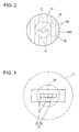
- the light-emitting portion 12 is formed by an LED substrate 13 having a horizontally long shape corresponding to the recess 11 and being held in the recess 11, and a plurality of LEDs (in the present embodiment, white LEDs) 14 arranged on the surface of the LED substrate 13. As shown in FIG. 3 , the plurality of LEDs 14 are arranged side by side in the direction in which the LED substrate 13 extends. Specifically, four 1-mm square LEDs 14 are arranged side by side in the lateral direction. A horizontally long orientation pattern can be obtained based on this horizontally long arrangement of the LEDs 14.
- a translucent member 15 is of a rotating body type, and is attached to the front surface 10a of the translucent-member attaching portion 10.
- a rear surface 16 of the translucent member 15 includes a circular central surface portion 17 and a rear peripheral surface portion 18 whose diameter is increased as it extends from the outer edge of the central surface portion 17 forward.
- a front surface 19 of the translucent member 15 extends rearward in a gradually curved manner from the tip end of the rear peripheral surface portion 18 in the radially inward direction.
- the central surface portion 17 of the rear surface 16 of the translucent member is attached to the translucent-member attaching portion 10 of the support member 7.
- the translucent member 15 is thus disposed so that its front surface 19 is located forward of its rear surface 16 and faces the front cover 3.
- a hemispherical accommodating hole 20 is formed in the central surface portion 17 of the translucent member 15. With the central surface portion 17 being attached to the translucent-member attaching portion 10, the plurality of LEDs 14 are accommodated in the accommodating hole 20. Thus, light rays from the plurality of LEDs 14 are incident on the translucent member 15 from the central surface portion 17 (i.e., the rear side) of the translucent member 15 through the accommodating hole 20.
- reference numeral 21 denotes a screw hole that fastens the translucent member 15 to the support member 7.
- the rearmost part of the front surface 19 of the translucent member 15 is positioned on an optical axis Lx, and the LEDs 14 are also arranged on this optical axis Lx.
- the front surface 19 is formed so as to totally reflect light rays Li from the light-emitting portion 12 to produce reflected light Lo.
- the front surface 19 is formed so that each light ray Li from the LEDs 14 is incident on the front surface 19 at a predetermined incident angle equal to or larger than a critical angle.
- the reflection direction of the reflected light (i.e., the totally reflected light) Lo is determined by whether the light ray (i.e., the incident light) Li from the light-emitting portion 12 is incident on the upper side or the lower side of the front surface 19 of the translucent member with respect to the optical axis Lx. If the light ray Li from the light-emitting portion 12 is incident on the upper side of the front surface 19 of the translucent member with respect to the optical axis Lx, the reflected light Lo is reflected outward in the radial direction of the translucent member 15 in the area located above the optical axis Lx.
- the reflected light Lo is reflected outward in the radial direction of the translucent member 15 in the area located below the optical axis Lx (see FIG. 4 ).
- the light ray Li is located farther away from the optical axis Lx, the light ray Li is incident on the front surface 19 of the translucent member at a larger incident angle ⁇ and critical conditions are more likely to be satisfied.
- the angle between a normal to the front surface 19 of the translucent member and the optical axis Lx can be reduced.
- the entire rear peripheral surface portion 18 is formed as a rotating body type, and due to its shape described above, serves as a region capable of receiving the reflected light Lo from the front surface 19 of the translucent member.
- the rear peripheral surface portion 18 is designed so that all of the reflected light Lo from the front surface 19 of the translucent member is incident on the rear peripheral surface portion 18 of the rear surface 16 of the translucent member.
- the rear peripheral surface portion 18 of the rear surface 16 of the translucent member is shaped so as to totally reflect the reflected light Lo from the front surface 19 of the translucent member to produce re-reflected light Loo. Specifically, as shown in FIG.
- the rear peripheral surface portion 18 of the rear surface 16 of the translucent member is formed by a plurality of segments (i.e., portions) 18a.
- each segment 18a (dashed line 18al in FIG. 2 represents a segment line on the rear surface 16) is designed so that a tilt angle ⁇ is " ⁇ ⁇ 90° - 2 ⁇ - y" when the reflected light Lo from the front surface 19 of the translucent member is incident on the rear peripheral surface portion 18 of the rear surface 16 of the translucent member at the tilt angle ⁇ with respect to the vertical direction, where ⁇ represents a critical angle, and ⁇ represents a shift angle (i.e. a refraction angle) of the re-reflected light Loo with respect to the horizontal direction.
- P1 represents a reflection point of the light ray (i.e., the incident light) Li from the light-emitting portion 12 on the front surface 19 of the translucent member
- P2 represents a reflection point of the reflected light Lo on the rear surface 16 of the translucent member (each segment 18a of the rear peripheral surface portion 18)
- L1 and L2 represent vertical lines extending through P1 and P2, respectively
- ⁇ represents a tilt angle formed by the vertical line L1 and the reflected light Lo.
- the angle formed by the vertical line L2 and an extended line Lo' of the reflected light Lo from the front surface 19 of the translucent member is also ⁇ , as the tilt angle and this angle are corresponding angles.
- P3 represents an incident point of the re-reflected light Loo on the front surface 19 of the translucent member.
- "90° - ⁇ - ⁇ " needs to satisfy the conditional expression of "90° - ⁇ - ⁇ > 2 ⁇ .”
- the tilt angle ⁇ formed by the vertical line L1 and the reflected light Lo at the front surface 19 of the translucent member is adjusted to cause total reflection at the front surface 19 of the translucent member (where the incident angle ⁇ is equal to or larger than the critical angle), and to satisfy the above conditional expression, in order to cause total reflection at both the front surface 19 and the rear surface 16 of the translucent member 15.
- the angle ⁇ need not be such an angle that causes total reflection at the front surface 19 of the translucent member, and need only satisfy the above conditional expression.
- each light ray Li from the light-emitting portion 12 is totally reflected by the front surface 19 of the translucent member, and the reflected light (i.e., the totally reflected light) Lo travels to the rear peripheral surface portion 18 of the rear surface 16 of the translucent member. Then, the reflected light Lo is totally reflected by the rear peripheral surface portion 18 of the rear surface 16 of the translucent member, and the re-reflected light Loo passes through the front surface 19 of the translucent member and the front cover 3, and is emitted to the front of the vehicular illumination lamp 1.
- the vehicular illumination lamp 1 when emitting light to the front of such a vehicular illumination lamp 1, light can be internally reflected by the front surface 19 and the rear surface 16 of the translucent member 15 by total reflection without using a vapor-deposited film. Thus, no vapor deposition need be performed on any location in order to cause internal reflection. This eliminates the need for a special facility for the vapor deposition, and thus eliminates the need for a special process using the special facility. As such, the vehicular illumination lamp 1 is easier to manufacture, and can enhance productivity.
- FIGS. 6 to 9 show a second embodiment.
- the same components as those of the first embodiment are denoted with the same reference characters, and description thereof will be omitted.
- the second embodiment shows a vehicular illumination lamp in which the front surface 19 of the translucent member 15 is formed as a non-rotating body.
- the front surface 19 of the translucent member 15 is formed as a non-rotating body because forming the front surface 19 of the translucent member as a rotating body may create an impression that the vehicular illumination lamp has a round design, which may be undesirable in certain circumstances.
- the front surface 19 is formed so that the incident angle of each light ray Li from the LEDs 14 is a predetermined angle equal to or larger than the critical angle. Each light ray Li is thus totally reflected, and the reflected light Lo travels substantially outward in the radial direction of the translucent member 15.
- the front surface 19 since the front surface 19 is formed as a non-rotating body, the front surface 19 reflects each light ray Li so that the reflected light Lo is bent toward a vertical cross section (shown by chain line) L, extending through the light-emitting portion 12, with respect to each light ray Li as viewed from the front ( FIG. 7 ).
- the bend angle ⁇ of each reflected light ray Lo increases as the reflected light ray Lo is located farther away from the vertical cross section L (in FIG. 7 , located farther away from the vertical cross section L in the lateral direction). It should be understood that such reflected light (i.e.
- the rear surface 16 of the translucent member can be formed not only as a rotating body but also as a non-rotating body. In that case, the rear surface 16 of the translucent member is shaped so as to be located farther away from the rear surface 16 of the translucent member formed as a rotating body as the bend angle of the reflected light Lo described above increases.
- Each light ray Li from the LEDs 14 is emitted toward the front of the translucent member 15 by such a rear peripheral surface portion 18 and the front surface 19 of the translucent member.
- FIGS. 10 to 13 show computer graphics images of the configuration in FIGS. 6 to 9 in order to more specifically show the configuration.
- FIG. 10 is a top view
- FIG. 11 is a rear view
- FIG. 12 is a side view
- FIG. 13 is a front view.
- Each figure shows only the upper half, and the lower half is symmetrical with the upper half.
- a portion A in FIG. 13 shows that the reflected light Lo from the front surface 19 of the translucent member is bent as viewed from the front, because the front surface 19 of the translucent member is formed as a non-rotating body.
Landscapes
- Engineering & Computer Science (AREA)
- General Engineering & Computer Science (AREA)
- Physics & Mathematics (AREA)
- Microelectronics & Electronic Packaging (AREA)
- Optics & Photonics (AREA)
- Non-Portable Lighting Devices Or Systems Thereof (AREA)
- Optical Elements Other Than Lenses (AREA)
Abstract
Description
- This application claims the benefit of priority of Japanese Patent Application No.
2012·179008 filed on August 10, 2012 - The present disclosure relates to vehicular illumination lamps capable of enhancing productivity.
- As described in Japanese Patent Application Laid-Open (Kokai) No.
2009-224303 - Specifically, in this vehicular illumination lamp, a part of the front surface of the translucent member is subjected to a vapor deposition (i.e., a mirror finish) in order to internally reflect the right rays from the light source, and most of the rear surface of the translucent member is subjected to a vapor deposition (i.e., a mirror finish) in order to internally reflect the reflected light from the front surface of the translucent member. With this structure, each light ray from the light source is emitted to the front of the translucent member by using the internal reflection at the front and rear surfaces of the translucent member.
- In the foregoing vehicular illumination lamp, the front and rear surfaces of the translucent member need to be subjected to the vapor deposition. This requires a special facility for the vapor deposition, and additionally requires a special process using the special facility.
- The present invention was developed in view of the problem of the related art, and it is an object of the present invention to provide a vehicular illumination lamp can be manufactured more easily, in order to enhance productivity.
- In order to achieve the above object, according to an aspect of the present invention, a vehicular illumination lamp includes: a translucent member; and a light source that causes light rays to be incident on the translucent member from a rear side of the translucent member, wherein a front surface of the translucent member is formed so as to reflect incident light to produce reflected light when the light rays from the light source are incident on the front surface of the translucent member as the incident light, and a rear surface of the translucent member is formed so as to receive the reflected light as incident light and is formed so as to reflect the reflected light to a front of the translucent member as re-reflected light, and at least one of the front surface and the rear surface of the translucent member is shaped so as to totally reflect the incident light on the at least one of the front surface and the rear surface of the translucent member in an entire region capable of receiving the incident light. Preferred modes of claim 1 are as described in
claim 2 and the subsequent claims. - According to some implementations, at least one of the front surface and the rear surface of the translucent member is shaped so as to totally reflect the incident light on the at least one of the front surface and the rear surface of the translucent member in the entire region capable of receiving the incident light. Thus, internal reflection can be caused by the total reflection without using a vapor-deposited film. This can reduce the number of locations that need be subjected to a vapor deposition as compared to conventional examples. Accordingly, the vehicular illumination lamp can be manufactured more easily, and can enhance productivity.
- In some implementations, each of the front surface and the rear surface of the translucent member is shaped so as to totally reflect the incident light on that surface in the entire region capable of receiving the incident light in that surface. Thus, internal reflection can be caused by the total reflection at the front and rear surfaces of the translucent member without using a vapor-deposited film, and no vapor deposition need be performed on any location in order to cause internal reflection. This can further reduce the complexity of the vehicular lamp, and can further enhance productivity.
- In some implementations, the front surface of the translucent member is shaped so that the light rays from the light source are incident on the front surface at a predetermined incident angle equal to or larger than a critical angle in the entire region capable of receiving the incident light in the front surface, and the rear surface of the translucent member is designed in shape so that at least in a vertical cross section including the light source, a tilt angle α is "α < 90° - 2β - y" when the reflected light from the front surface of the translucent member is incident on the rear surface of the translucent member at the tilt angle α with respect to a vertical direction, where β represents the critical angle, and γ represents a shift angle of the re-reflected light with respect to a horizontal direction. Thus, internal reflection can be specifically caused by the total reflection at the front and rear surfaces of the translucent member, and no vapor deposition need be specifically performed on any location on the front and rear surfaces of the translucent member in order to cause internal reflection.
In this case, "90°" is included as a reference value (i.e., a maximum value) in the conditional expression "α < 90° - 2β - y" because a balanced equation can be formed by including α, 2β, and γ within the angular range of 90° with respect to the direction in which light is emitted from the translucent member (i.e., the horizontal direction). This is condition expression, α is the tilt angle of the reflected light from the front surface of the translucent member with respect to the vertical direction, 2β is the angle that causes total reflection, and γ is the shift angle (i.e., the refraction angle) of the re-reflected light with respect to the direction in which the re-reflected light is emitted to the outside of the translucent member (i.e., the horizontal direction). The term "-2β refers to the sum of the incident angle and the reflection angle when the total reflection occurs, and has been included in order to account for conditions where total reflection occurs. The term "- y" is included because the shift angle (refraction angle) of the re-reflected light, with respect to the direction in which the re-reflected light is emitted to the outside of the translucent member, needs to be added if the direction in which the re-reflected light is emitted to the outside of the translucent member is the horizontal direction. - In some implementations, the front surface of the translucent member is shaped so as to totally reflect the light rays from the light source in the entire region capable of receiving the incident light in the front surface. Thus, internal reflection can be specifically caused by the total reflection at the front surface of the translucent member, and no vapor deposition need be performed on any location on the front surface of the translucent member in order to cause internal reflection.
- In some implementations, the front surface of the translucent member is designed in shape so that the light rays from the light source are incident on the front surface of the translucent member at a predetermined incident angle equal to or larger than a critical angle in the entire region capable of receiving the incident light in the front surface. Thus, the light rays from the light source can be specifically totally reflected by the front surface of the translucent member, and no vapor deposition need be specifically performed on any location on the front surface of the translucent member in order to cause internal reflection.
- In some implementations, the rear surface of the translucent member is shaped so as to totally reflect the reflected light from the front surface of the translucent member in the entire region capable of receiving the incident light in the rear surface. Thus, the re-reflected light can be emitted to the front of the translucent member by total reflection at the rear surface of the translucent member, and no vapor deposition need be performed on any location on the rear surface of the translucent member in order to cause internal reflection.
- In some implementations, the rear surface of the translucent member is designed in shape so that, at least in a vertical cross section including the light source, a tilt angle α is "α < 90° - 2β - y" when the reflected light from the front surface of the translucent member is incident on the rear surface of the translucent member at the tilt angle α with respect to a vertical direction, where β represents a critical angle, and γ represents a shift angle of the re-reflected light with respect to a horizontal direction. Thus, internal reflection can be specifically caused by the total reflection at the rear surface of the translucent member, and no vapor deposition need be specifically performed on any location on the rear surface of the translucent member in order to cause internal reflection.
Other aspects, features and advantages will be readily apparent from the following detailed description, the accompanying the claims. -
-
FIG. 1 is a vertical sectional view showing a vehicular illumination lamp according to a first embodiment. -
FIG. 2 is a front view showing a translucent member of the vehicular illumination lamp according to the first embodiment. -
FIG. 3 is an illustration illustrating an arrangement of LEDs with respect to the translucent member according to the first embodiment. -
FIG. 4 is an illustration illustrating the effects of a front surface of the translucent member on incident light according to the first embodiment. -
FIG. 5 is an illustration illustrating the effects of incident light on a rear peripheral surface portion (rear surface) of the translucent member according to the first embodiment. -
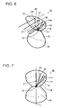
FIG. 6 is an illustration illustrating the effects of right rays on a translucent member according to a second embodiment. -
FIG. 7 is a front view ofFIG. 6 . -
FIG. 8 is a top view ofFIG. 6 . -
FIG. 9 is a side view ofFIG. 6 . -
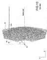
FIG. 10 shows a computer graphics image of a front surface and a rear peripheral portion of the translucent member according to the second embodiment as viewed from the top. -
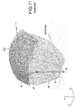
FIG. 11 shows a computer graphics image of the front surface and the rear peripheral portion of the translucent member according to the second embodiment as viewed from the rear. -
FIG. 12 shows a computer graphics image of the front surface and the rear peripheral portion of the translucent member according to the second embodiment as viewed from the side. -
FIG. 13 shows a computer graphics image of the front surface and the rear peripheral portion of the translucent member according to the second embodiment as viewed from the front. - Examples of the present invention are described below with reference to the accompanying drawings.
InFIG. 1 , reference numeral 1 denotes a vehicular illumination lamp according to a first embodiment. The exterior of the vehicular illumination lamp 1 is formed by alamp body 2 opening at its front, and afront cover 3 covering the opening of thelamp body 2. Thelamp body 2 is formed by aback wall portion 2a standing in the vertical direction, and aperipheral wall portion 2b protruding forward from the peripheral edge of theback wall portion 2a. Theback wall portion 2a and theperipheral wall portion 2b define anaccommodating space 4, and the tip end of theperipheral wall portion 2b defines anopening 5 that opens theaccommodating space 4 to the outside. Thefront cover 3 is detachably attached the tip end of theperipheral wall portion 2b of thelamp body 2. Thefront cover 3 is made of a translucent material, and thefront cover 3 and thelamp body 2 form a sealedspace 6. - As shown in
FIG. 1 , a plate-like support member 7 made of a metal (e.g., an aluminum die cast product) 7 is disposed in the sealedspace 6. Thesupport member 7 is supported by theback wall portion 2a of thelamp body 2 via a plurality of aimingscrews 8, and is placed such that the plate surface of thesupport member 7 faces the longitudinal direction and is separated forward from theback wall portion 2a by a fixed distance. Arear surface 7a (the right surface inFIG. 1 ) of thesupport member 7 as a flat surface faces theback wall portion 2a of thelamp body 2, and aheat dissipating fin 9 that dissipates heat is attached to therear surface 7a. A translucent-member attaching portion 10 is formed on the central part of afront surface 7b (the left surface inFIG. 1 ) of thesupport member 7, where the central part refers to the central part in both the lateral direction (e.g., the lateral direction inFIG. 2 ) and the vertical direction (e.g., the vertical direction inFIG. 1 ). The translucent-member attaching portion 10 is formed by making thesupport member 7 thicker than the remaining part of thesupport member 7. Afront surface 10a of the translucent-member attaching portion 10 as a flat surface faces forward. A horizontallylong recess 11 is formed in the central part of thefront surface 10a of the translucent-member attaching portion 10, and a light-emittingportion 12 forming a light source is held in therecess 11. The light-emittingportion 12 is formed by anLED substrate 13 having a horizontally long shape corresponding to therecess 11 and being held in therecess 11, and a plurality of LEDs (in the present embodiment, white LEDs) 14 arranged on the surface of theLED substrate 13. As shown inFIG. 3 , the plurality ofLEDs 14 are arranged side by side in the direction in which theLED substrate 13 extends. Specifically, four 1-mmsquare LEDs 14 are arranged side by side in the lateral direction. A horizontally long orientation pattern can be obtained based on this horizontally long arrangement of theLEDs 14. - As shown in
FIG. 1 , atranslucent member 15 is of a rotating body type, and is attached to thefront surface 10a of the translucent-member attaching portion 10. Arear surface 16 of thetranslucent member 15 includes a circularcentral surface portion 17 and a rearperipheral surface portion 18 whose diameter is increased as it extends from the outer edge of thecentral surface portion 17 forward. Afront surface 19 of thetranslucent member 15 extends rearward in a gradually curved manner from the tip end of the rearperipheral surface portion 18 in the radially inward direction. Thecentral surface portion 17 of therear surface 16 of the translucent member is attached to the translucent-member attaching portion 10 of thesupport member 7. Thetranslucent member 15 is thus disposed so that itsfront surface 19 is located forward of itsrear surface 16 and faces thefront cover 3. A hemisphericalaccommodating hole 20 is formed in thecentral surface portion 17 of thetranslucent member 15. With thecentral surface portion 17 being attached to the translucent-member attaching portion 10, the plurality ofLEDs 14 are accommodated in theaccommodating hole 20. Thus, light rays from the plurality ofLEDs 14 are incident on thetranslucent member 15 from the central surface portion 17 (i.e., the rear side) of thetranslucent member 15 through theaccommodating hole 20. InFIG. 2 ,reference numeral 21 denotes a screw hole that fastens thetranslucent member 15 to thesupport member 7. The rearmost part of thefront surface 19 of thetranslucent member 15 is positioned on an optical axis Lx, and theLEDs 14 are also arranged on this optical axis Lx. - The entire
front surface 19 of thetranslucent member 15, which is formed as a rotating body type, serves as a region capable of receiving incident light from the light-emittingportion 12. Thefront surface 19 is formed so as to totally reflect light rays Li from the light-emittingportion 12 to produce reflected light Lo. Specifically, thefront surface 19 is formed so that each light ray Li from theLEDs 14 is incident on thefront surface 19 at a predetermined incident angle equal to or larger than a critical angle. When each light ray from the light-emittingportion 12 is incident on thefront surface 19 of thetranslucent member 15 as incident light, each light ray Li is totally reflected, and the reflected light Lo travels substantially outward in the radial direction of the translucent member 15 (seeFIG. 1 ).
More specifically, as shown inFIG. 4 , the reflection direction of the reflected light (i.e., the totally reflected light) Lo is determined by whether the light ray (i.e., the incident light) Li from the light-emittingportion 12 is incident on the upper side or the lower side of thefront surface 19 of the translucent member with respect to the optical axis Lx. If the light ray Li from the light-emittingportion 12 is incident on the upper side of thefront surface 19 of the translucent member with respect to the optical axis Lx, the reflected light Lo is reflected outward in the radial direction of thetranslucent member 15 in the area located above the optical axis Lx. If the light ray Li is incident on the lower side of thefront surface 19 of the translucent member with respect to the optical axis Lx, the reflected light Lo is reflected outward in the radial direction of thetranslucent member 15 in the area located below the optical axis Lx (seeFIG. 4 ). In this case, as the light ray Li is located farther away from the optical axis Lx, the light ray Li is incident on thefront surface 19 of the translucent member at a larger incident angle θ and critical conditions are more likely to be satisfied. In addition, the angle between a normal to thefront surface 19 of the translucent member and the optical axis Lx can be reduced. - Of the
rear surface 16 of thetranslucent member 15, the entire rearperipheral surface portion 18 is formed as a rotating body type, and due to its shape described above, serves as a region capable of receiving the reflected light Lo from thefront surface 19 of the translucent member. The rearperipheral surface portion 18 is designed so that all of the reflected light Lo from thefront surface 19 of the translucent member is incident on the rearperipheral surface portion 18 of therear surface 16 of the translucent member. The rearperipheral surface portion 18 of therear surface 16 of the translucent member is shaped so as to totally reflect the reflected light Lo from thefront surface 19 of the translucent member to produce re-reflected light Loo. Specifically, as shown inFIG. 2 , the rearperipheral surface portion 18 of therear surface 16 of the translucent member is formed by a plurality of segments (i.e., portions) 18a. As shown inFIG. 5 , eachsegment 18a (dashed line 18al inFIG. 2 represents a segment line on the rear surface 16) is designed so that a tilt angle α is "α < 90° - 2β - y" when the reflected light Lo from thefront surface 19 of the translucent member is incident on the rearperipheral surface portion 18 of therear surface 16 of the translucent member at the tilt angle α with respect to the vertical direction, where β represents a critical angle, and γ represents a shift angle (i.e. a refraction angle) of the re-reflected light Loo with respect to the horizontal direction. - This will be described in detail with reference to
FIG. 5 . P1 represents a reflection point of the light ray (i.e., the incident light) Li from the light-emittingportion 12 on thefront surface 19 of the translucent member, P2 represents a reflection point of the reflected light Lo on therear surface 16 of the translucent member (eachsegment 18a of the rear peripheral surface portion 18), L1 and L2 represent vertical lines extending through P1 and P2, respectively, and α represents a tilt angle formed by the vertical line L1 and the reflected light Lo. In this case, the angle formed by the vertical line L2 and an extended line Lo' of the reflected light Lo from thefront surface 19 of the translucent member is also α, as the tilt angle and this angle are corresponding angles. Since a horizontal line Lh (which extends in the direction in which light is emitted and extends through the re-reflection point P2 on therear surface 16 of the translucent member) and the vertical line L2 form an angle of 90°, the angle formed by the horizontal line Lh and the extended line Lo' of the reflected light Lo is "90° - α," and its vertically opposite angle formed by the horizontal line Lh and the reflected light Lo is "90° - α." In this case, in order for the reflected light Lo to be totally reflected by therear surface 16 of the translucent member and for the re-reflected light Loo to be emitted forward from thefront surface 19 of the translucent member in the horizontal direction, an angle for total reflection (i.e., angle 2β, which is twice the critical angle β provided that the incident angle and the reflection angle are equal to the critical angle β) needs to be within the angular range of "90° - α - y," in view of the fixed shift angle (i.e., the refraction angle) γ with respect to the direction in which light is emitted from thefront surface 19 of the translucent member (i.e., the horizontal direction). InFIG. 5 , P3 represents an incident point of the re-reflected light Loo on thefront surface 19 of the translucent member. "90° - α - γ" needs to satisfy the conditional expression of "90° - α - γ > 2β." Thus, in the present embodiment, the tilt angle α formed by the vertical line L1 and the reflected light Lo at thefront surface 19 of the translucent member is adjusted to cause total reflection at thefront surface 19 of the translucent member (where the incident angle θ is equal to or larger than the critical angle), and to satisfy the above conditional expression, in order to cause total reflection at both thefront surface 19 and therear surface 16 of thetranslucent member 15.
It should be understood that in order to cause total reflection only at therear surface 16 of the translucent member and not at thefront surface 19 of the translucent member, the angle α need not be such an angle that causes total reflection at thefront surface 19 of the translucent member, and need only satisfy the above conditional expression. - In such a vehicular illumination lamp 1, as shown in
FIG. 1 , each light ray Li from the light-emittingportion 12 is totally reflected by thefront surface 19 of the translucent member, and the reflected light (i.e., the totally reflected light) Lo travels to the rearperipheral surface portion 18 of therear surface 16 of the translucent member. Then, the reflected light Lo is totally reflected by the rearperipheral surface portion 18 of therear surface 16 of the translucent member, and the re-reflected light Loo passes through thefront surface 19 of the translucent member and thefront cover 3, and is emitted to the front of the vehicular illumination lamp 1.
Accordingly, when emitting light to the front of such a vehicular illumination lamp 1, light can be internally reflected by thefront surface 19 and therear surface 16 of thetranslucent member 15 by total reflection without using a vapor-deposited film. Thus, no vapor deposition need be performed on any location in order to cause internal reflection. This eliminates the need for a special facility for the vapor deposition, and thus eliminates the need for a special process using the special facility. As such, the vehicular illumination lamp 1 is easier to manufacture, and can enhance productivity. -
FIGS. 6 to 9 (andFIGS. 10 to 13 described later) show a second embodiment. In the second embodiment, the same components as those of the first embodiment are denoted with the same reference characters, and description thereof will be omitted. - The second embodiment shows a vehicular illumination lamp in which the
front surface 19 of thetranslucent member 15 is formed as a non-rotating body. Thefront surface 19 of thetranslucent member 15 is formed as a non-rotating body because forming thefront surface 19 of the translucent member as a rotating body may create an impression that the vehicular illumination lamp has a round design, which may be undesirable in certain circumstances.
As in the first embodiment, in such atranslucent member 15 as well, thefront surface 19 is formed so that the incident angle of each light ray Li from theLEDs 14 is a predetermined angle equal to or larger than the critical angle. Each light ray Li is thus totally reflected, and the reflected light Lo travels substantially outward in the radial direction of thetranslucent member 15. However, since thefront surface 19 is formed as a non-rotating body, thefront surface 19 reflects each light ray Li so that the reflected light Lo is bent toward a vertical cross section (shown by chain line) L, extending through the light-emittingportion 12, with respect to each light ray Li as viewed from the front (FIG. 7 ). The bend angle ε of each reflected light ray Lo increases as the reflected light ray Lo is located farther away from the vertical cross section L (inFIG. 7 , located farther away from the vertical cross section L in the lateral direction).
It should be understood that such reflected light (i.e. totally reflected light) Lo from thefront surface 19 also subsequently travels toward the rearperipheral surface portion 18 of therear surface 16 of the translucent member, and is totally reflected by the rearperipheral surface portion 18. The re-reflected light Loo passes through thefront surface 19 of the translucent member and thefront cover 3 and is emitted to the front of the vehicular illumination lamp 1.
In this example, therear surface 16 of the translucent member can be formed not only as a rotating body but also as a non-rotating body. In that case, therear surface 16 of the translucent member is shaped so as to be located farther away from therear surface 16 of the translucent member formed as a rotating body as the bend angle of the reflected light Lo described above increases. Each light ray Li from theLEDs 14 is emitted toward the front of thetranslucent member 15 by such a rearperipheral surface portion 18 and thefront surface 19 of the translucent member. -
FIGS. 10 to 13 show computer graphics images of the configuration inFIGS. 6 to 9 in order to more specifically show the configuration.FIG. 10 is a top view,FIG. 11 is a rear view,FIG. 12 is a side view, andFIG. 13 is a front view. Each figure shows only the upper half, and the lower half is symmetrical with the upper half. In this case, a portion A inFIG. 13 shows that the reflected light Lo from thefront surface 19 of the translucent member is bent as viewed from the front, because thefront surface 19 of the translucent member is formed as a non-rotating body. - Although various embodiments are described above, the present disclosure describes the following features applicable in some implementations.
- (1) Instead of totally reflecting light from both the
front surface 19 and the rearperipheral surface portion 18 of thetranslucent member 15, light is totally reflected only by one of them, namely thefront surface 19 of the translucent member, and the reflected light from thefront surface 19 of the translucent member is reflected again by the rearperipheral surface portion 18 of thetranslucent member 15 by using a vapor-deposited film. This can enhance the productivity of the vehicular illumination lamp as compared to the case where a vapor-deposited film is used in both thefront surface 19 and therear surface 16 of thetranslucent member 15. - (2) Instead of totally reflecting light from both the
front surface 19 and the rearperipheral surface portion 18 of thetranslucent member 15, light is totally reflected only by one of them, namely the rearperipheral surface portion 18 of thetranslucent member 15, and the reflected light from thefront surface 19 of the translucent member is reflected again by thefront surface 19 of thetranslucent member 15 by using a vapor-deposited film. This can also enhance the productivity of the vehicular illumination lamp as compared to the case where a vapor-deposited film is used in both thefront surface 19 and therear surface 16 of thetranslucent member 15.
In this case, the angle α formed by the vertical line L1 and the reflected light at thefront surface 19 of the translucent member need not be such an angle that causes total reflection from thefront surface 19 of the translucent member, and need only satisfy the conditional expression "90° - α - γ < 2β" at least in a vertical cross section including the light source in the rearperipheral surface portion 18. -
- 1
- VEHICULAR ILLUMINATION LAMP
- 12
- LIGHT-EMITTING PORTION (LIGHT SOURCE)
- 14
- LED
- 15
- TRANSLUCENT MEMBER
- 16
- REAR SURFACE OF TRANSLUCENT MEMBER
- 18
- REAR PERIPHERAL SURFACE PORTION OF REAR SURFACE
- 19
- FRONT SURFACE OF TRANSLUCENT MEMBER
- Li
- LIGHT RAY FROM LIGHT-EMITTING PORTION (INCIDENT LIGHT)
- Lo
- REFLECTED LIGHT
- Loo
- RE-REFLECTED LIGHT
- β
- CRITICAL ANGLE
- γ
- SHIFT ANGLE WITH RESPECT TO HORIZONTAL DIRECTION (REFRACTION ANGLE)
Claims (7)
- A vehicular illumination lamp comprising:a translucent member (15); anda light source (12) that causes light rays to be incident on the translucent member (15) from a rear side (16) of the translucent member (15), whereina front surface (19) of the translucent member (15) is formed so as to reflect incident light (Li) to produce reflected light (Lo) when the light rays (Li) from the light source (12) are incident on the front surface (19) of the translucent member (15) as the incident light, and a rear surface (18) of the translucent member (15) is formed so as to receive the reflected light (Lo) as incident light and is formed so as to reflect the reflected light (Lo) to a front of the translucent member (15) as re-reflected light ((Loo), andat least one of the front surface (19) and the rear surface (18) of the translucent member (15) is shaped so as to totally reflect the incident light (Li, Lo) on the at least one of the front surface (19) and the rear surface (18) of the translucent member (15) in an entire region capable of receiving the incident light (Li, Lo).
- The vehicular illumination lamp according to claim 1, wherein
each of the front surface (19) and the rear surface (18) of the translucent member (15) is shaped so as to totally reflect the incident light (Li, Lo) on that surface (19,18) in the entire region capable of receiving the incident light (Li, Lo) in that surface (19,18). - The vehicular illumination lamp according to claim 2, wherein
the front surface (19) of the translucent member (15) is shaped so that the light rays (Li) from the light source (12) are incident on the front surface (19) at a predetermined incident angle equal to or larger than a critical angle (β) in the entire region capable of receiving the incident light (Li) in the front surface (19), and
the rear surface (18) of the translucent member (15) is designed in shape so that at least in a vertical cross section including the light source (12), a tilt angle α is "α < 90°-2β - γ" when the reflected light (Lo) from the front surface (19) of the translucent member (15) is incident on the rear surface (18) of the translucent member (15) at the tilt angle α with respect to a vertical direction (L2), where β represents the critical angle, and γ represents a shift angle of the re-reflected light (Loo) with respect to a horizontal direction. - The vehicular illumination lamp according to claim 1, wherein
the front surface (19) of the translucent member (15) is shaped so as to totally reflect the light rays (Li) from the light source (12) in the entire region capable of receiving the incident light (Li) in the front surface (19). - The vehicular illumination lamp according to claim 4, wherein
the front surface (19) of the translucent member (15) is designed in shape so that the light rays (Li) from the light source (12) are incident on the front surface (19) of the translucent member (15) at a predetermined incident angle equal to or larger than a critical angle (β) in the entire region capable of receiving the incident light (Li) in the front surface (19). - The vehicular illumination lamp according to claim 1, wherein
the rear surface (18) of the translucent member (15) is shaped so as to totally reflect the reflected light (Lo) from the front surface (19) of the translucent member (15) in the entire region capable of receiving the incident light (Lo) in the rear surface (18). - The vehicular illumination lamp according to claim 6, wherein
the rear surface (18) of the translucent member (15) is designed in shape so that at least in a vertical cross section including the light source (12), a tilt angle α is "α < 90°-2β - γ" when the reflected light (Lo) from the front surface (19) of the translucent member (15) is incident on the rear surface (18) of the translucent member (15) at the tilt angle α with respect to a vertical direction (L2), where β represents a critical angle, and γ represents a shift angle of the re-reflected light (Loo) with respect to a horizontal direction.
Applications Claiming Priority (1)
| Application Number | Priority Date | Filing Date | Title |
|---|---|---|---|
| JP2012179008A JP5988764B2 (en) | 2012-08-10 | 2012-08-10 | Lighting fixtures for vehicles |
Publications (2)
| Publication Number | Publication Date |
|---|---|
| EP2696133A2 true EP2696133A2 (en) | 2014-02-12 |
| EP2696133A3 EP2696133A3 (en) | 2018-03-21 |
Family
ID=48979576
Family Applications (1)
| Application Number | Title | Priority Date | Filing Date |
|---|---|---|---|
| EP13179808.4A Withdrawn EP2696133A3 (en) | 2012-08-10 | 2013-08-09 | Vehicular illumination lamp |
Country Status (4)
| Country | Link |
|---|---|
| US (1) | US20140043841A1 (en) |
| EP (1) | EP2696133A3 (en) |
| JP (1) | JP5988764B2 (en) |
| CN (1) | CN103574496A (en) |
Citations (1)
| Publication number | Priority date | Publication date | Assignee | Title |
|---|---|---|---|---|
| JP2009224303A (en) | 2008-02-22 | 2009-10-01 | Koito Mfg Co Ltd | Vehicular lighting fixture |
Family Cites Families (11)
| Publication number | Priority date | Publication date | Assignee | Title |
|---|---|---|---|---|
| US2254962A (en) * | 1937-09-22 | 1941-09-02 | George M Cressaty | Unitary lens system |
| US6679621B2 (en) * | 2002-06-24 | 2004-01-20 | Lumileds Lighting U.S., Llc | Side emitting LED and lens |
| JP4162935B2 (en) * | 2002-07-04 | 2008-10-08 | 株式会社小糸製作所 | Vehicle lighting |
| JP4339028B2 (en) * | 2003-06-19 | 2009-10-07 | 株式会社小糸製作所 | Lamp unit and vehicle headlamp |
| JP2005158362A (en) * | 2003-11-21 | 2005-06-16 | Stanley Electric Co Ltd | Vehicle lighting |
| JP4113111B2 (en) * | 2003-12-24 | 2008-07-09 | 株式会社小糸製作所 | VEHICLE LIGHT UNIT AND VEHICLE LIGHTING LIGHT |
| DE102004026530B3 (en) * | 2004-05-29 | 2006-02-02 | Fer Fahrzeugelektrik Gmbh | optical body |
| JP5350771B2 (en) * | 2008-12-24 | 2013-11-27 | 株式会社小糸製作所 | Lighting fixtures for vehicles |
| JP5444568B2 (en) * | 2010-04-13 | 2014-03-19 | 株式会社エンプラス | Luminous flux control member, light emitting device, and illumination device |
| US8388198B2 (en) * | 2010-09-01 | 2013-03-05 | Illumination Management Solutions, Inc. | Device and apparatus for efficient collection and re-direction of emitted radiation |
| JP5567435B2 (en) * | 2010-09-06 | 2014-08-06 | 株式会社小糸製作所 | Vehicle lighting |
-
2012
- 2012-08-10 JP JP2012179008A patent/JP5988764B2/en not_active Expired - Fee Related
-
2013
- 2013-08-06 US US13/959,892 patent/US20140043841A1/en not_active Abandoned
- 2013-08-09 CN CN201310347219.4A patent/CN103574496A/en active Pending
- 2013-08-09 EP EP13179808.4A patent/EP2696133A3/en not_active Withdrawn
Patent Citations (1)
| Publication number | Priority date | Publication date | Assignee | Title |
|---|---|---|---|---|
| JP2009224303A (en) | 2008-02-22 | 2009-10-01 | Koito Mfg Co Ltd | Vehicular lighting fixture |
Also Published As
| Publication number | Publication date |
|---|---|
| JP2014038714A (en) | 2014-02-27 |
| US20140043841A1 (en) | 2014-02-13 |
| EP2696133A3 (en) | 2018-03-21 |
| CN103574496A (en) | 2014-02-12 |
| JP5988764B2 (en) | 2016-09-07 |
Similar Documents
| Publication | Publication Date | Title |
|---|---|---|
| US10215357B2 (en) | Vehicular lamp | |
| EP2088031A2 (en) | License plate lamp | |
| JP5369359B2 (en) | Lamp | |
| JP5567435B2 (en) | Vehicle lighting | |
| US8007138B2 (en) | Lighting device | |
| JP6029298B2 (en) | Vehicle lighting | |
| US9340147B2 (en) | Vehicle lamp | |
| JP5733129B2 (en) | Vehicle lighting | |
| US8672524B2 (en) | Rear lamp for vehicle | |
| US20110310630A1 (en) | Vehicular lamp | |
| US10030834B2 (en) | Light device for vehicle | |
| US20110032721A1 (en) | Vehicular lamp | |
| US7207703B2 (en) | Headlamp unit for vehicle and headlamp unit assembly | |
| US9528671B2 (en) | Laser optical system for head lamp | |
| WO2009018436A1 (en) | Asymmetric led bulb optic | |
| US9453632B2 (en) | Lamp for vehicle | |
| US20160010821A1 (en) | Laser Optical System for Headlamps | |
| JP6354175B2 (en) | Vehicle light guide member, vehicle lamp | |
| US10125945B2 (en) | Lamp apparatus for vehicle | |
| US8419230B2 (en) | Lens and lamp using the same | |
| US20170130925A1 (en) | Light patterning device and illuminating and/or signaling apparatus | |
| US20140043841A1 (en) | Vehicular illumination lamp | |
| US20150098227A1 (en) | Light source module of lamp for vehicle | |
| EP4435319A1 (en) | Vehicle lamp | |
| US7347601B2 (en) | Vehicle lamp unit |
Legal Events
| Date | Code | Title | Description |
|---|---|---|---|
| 17P | Request for examination filed |
Effective date: 20130809 |
|
| AK | Designated contracting states |
Kind code of ref document: A2 Designated state(s): AL AT BE BG CH CY CZ DE DK EE ES FI FR GB GR HR HU IE IS IT LI LT LU LV MC MK MT NL NO PL PT RO RS SE SI SK SM TR |
|
| AX | Request for extension of the european patent |
Extension state: BA ME |
|
| PUAI | Public reference made under article 153(3) epc to a published international application that has entered the european phase |
Free format text: ORIGINAL CODE: 0009012 |
|
| PUAL | Search report despatched |
Free format text: ORIGINAL CODE: 0009013 |
|
| AK | Designated contracting states |
Kind code of ref document: A3 Designated state(s): AL AT BE BG CH CY CZ DE DK EE ES FI FR GB GR HR HU IE IS IT LI LT LU LV MC MK MT NL NO PL PT RO RS SE SI SK SM TR |
|
| AX | Request for extension of the european patent |
Extension state: BA ME |
|
| RIC1 | Information provided on ipc code assigned before grant |
Ipc: F21S 8/10 20181130AFI20131120BHEP |
|
| RIC1 | Information provided on ipc code assigned before grant |
Ipc: F21S 8/10 20060101AFI20131120BHEP |
|
| STAA | Information on the status of an ep patent application or granted ep patent |
Free format text: STATUS: THE APPLICATION IS DEEMED TO BE WITHDRAWN |
|
| 18D | Application deemed to be withdrawn |
Effective date: 20180922 |