EP2696077A1 - Reduzieren eines Gasturbinenverdichterpumpens - Google Patents
Reduzieren eines Gasturbinenverdichterpumpens Download PDFInfo
- Publication number
- EP2696077A1 EP2696077A1 EP12179977.9A EP12179977A EP2696077A1 EP 2696077 A1 EP2696077 A1 EP 2696077A1 EP 12179977 A EP12179977 A EP 12179977A EP 2696077 A1 EP2696077 A1 EP 2696077A1
- Authority
- EP
- European Patent Office
- Prior art keywords
- gas turbine
- fluid
- controller
- compressor
- turbine compressor
- Prior art date
- Legal status (The legal status is an assumption and is not a legal conclusion. Google has not performed a legal analysis and makes no representation as to the accuracy of the status listed.)
- Granted
Links
Images
Classifications
-
- F—MECHANICAL ENGINEERING; LIGHTING; HEATING; WEAPONS; BLASTING
- F04—POSITIVE - DISPLACEMENT MACHINES FOR LIQUIDS; PUMPS FOR LIQUIDS OR ELASTIC FLUIDS
- F04D—NON-POSITIVE-DISPLACEMENT PUMPS
- F04D19/00—Axial-flow pumps
- F04D19/02—Multi-stage pumps
-
- F—MECHANICAL ENGINEERING; LIGHTING; HEATING; WEAPONS; BLASTING
- F04—POSITIVE - DISPLACEMENT MACHINES FOR LIQUIDS; PUMPS FOR LIQUIDS OR ELASTIC FLUIDS
- F04D—NON-POSITIVE-DISPLACEMENT PUMPS
- F04D27/00—Control, e.g. regulation, of pumps, pumping installations or pumping systems specially adapted for elastic fluids
- F04D27/02—Surge control
- F04D27/0207—Surge control by bleeding, bypassing or recycling fluids
- F04D27/0215—Arrangements therefor, e.g. bleed or by-pass valves
Definitions
- the present invention relates to a method and controller for reducing compressor pumping in a gas turbine compressor.
- the compressor map of a gas turbine compressor is divided by the so-called surge limit into a stable and an unstable region. If the operating point of the compressor in the unstable region lies, in particular by reducing the flow rate or increasing the delivery head, working fluid can flow back against the conveying direction of the compressor, in particular cyclically, into an upstream stage and be conveyed back therefrom. Through this so-called (compressor) pumps, the gas turbine can be charged.
- a Pumpverhütungs- or anti-pumping which opens a relief valve on the basis of the operating point of the compressor when approaching the surge limit or as a result of a pump pressure surge.
- Such anti-pump and anti-pump regulations operate electronically and are externally controlled by a gas turbine governor. To form these fail-safe, especially in the high safety requirements of aircraft engines, consuming.
- Object of the present invention is to reduce compressor pumps in a gas turbine compressor in an advantageous manner, in particular to prevent.
- a gas turbine compressor according to the preamble of claim 1 is further developed by its characterizing features.
- Claim 11 provides a method for operating such a gas turbine compressor under protection, the dependent claims relate to advantageous developments.
- a gas turbine compressor in particular an aircraft engine compressor, comprises two or more compressor stages and one or more bypass passages for returning working fluid from one or more downstream to one or more upstream stages, and an open and close regulator this Umblaspassage (s) to reduce a compressor pumps, in particular to prevent.
- working fluid may flow from one or more downstream stages to one or more upstream stages.
- a Umblaspassage two, in particular adjacent or successive compressor stages connect.
- one or more further blowby passages may connect the same and / or another downstream stage to the same and / or another upstream stage.
- the controller may be configured to open and close one or more bypass passages, in particular coupled or synchronous.
- the controller may only fully open or close one or more bypass passages. In another embodiment, the controller may also partially open or close one or more blow-over passages, in particular in predetermined discrete steps or continuously.
- One or more Umblaspassagen may open in the axial direction before, at or after a playpen a compressor stage in this, preferably radially outside or inside.
- the controller has one or more fluid-mechanically operable processing elements.
- One or more processing members are pneumatically operable in one embodiment by the working fluid. Additionally or alternatively, one or more processing members may be operable by another fluid.
- a fluid-mechanically operable processing element in the context of the present invention is understood to mean, in particular, a component that fluid-mechanically maps one or more input variables in a logical and / or arithmetic manner to one or more output variables, in particular a manipulated variable, in particular links two or more input variables to one another in a fluid-mechanical manner . interconnected.
- two or more processing members may be fluidly coupled together by providing one or more outputs of one processing element as input to another processing member be supplied fluid mechanically.
- Fluid-mechanical in the sense of the present invention may in particular mean “mechanically by a fluid”.
- controllers By one or more, preferably all processing elements of the controller are not electronically but fluid-mechanically actuated, can be provided in a simple manner, a reliable controller for reducing a gas turbine compressor pumping.
- a processing member in the sense of the present invention may also comprise a sensing member subjected to fluid-mechanical loading by the working medium of one or more compressor stages and / or a fluid-mechanically actuated actuator for opening or closing the bypass passage (s).
- a fluidmechanisch actuatable processing member which is acted upon by the working fluid of the downstream stage (detection member) and whose pressure with the spring preload is linked such control technology that when exceeding a - predetermined by the spring preload - value the Umblaspassage opened or closed when falling below this value (actuator).
- the controller is fluid-mechanically formed. This is understood to mean, in particular, that the controller operates purely fluid-mechanically, ie its entire controlled system from the input quantities to the actuating action (s) which open or close the bypass passage (s), exclusively by fluid mechanics, in particular by the working fluid of the compressor pneumatic, without the controller using electronic signals to control. As a result, the controller can continue to work, especially in the event of a power failure. Additionally or alternatively, the controller may be autonomous. This is understood to mean, in particular, that the controller only regulates as input variables on the basis of the working fluid, in particular in one or more upstream stages, or that the controller operates only on the basis of one or more fluid-mechanical variables of one or more compressor stages.
- one or more processing elements of the controller comprise one or more fluid-mechanical, in particular pneumatic, adders, subtractors, comparators, integrators, differentiators, dampers, filters and / or limiters.
- a filter is understood to mean, in particular, a means which functions as a filter as a filter and dampens predetermined frequencies of a fluid-mechanical quantity.
- a filter may also be a means which functions as a filter in terms of flow and removes foreign substances of a predetermined size from the fluid with which the regulator is actuated.
- a filter for this purpose can have one or more screens, nets or the like.
- one or more processing elements of the controller may have one or more fluid mechanical, in particular pneumatic, memory, in particular average and / or extreme value memory.
- one or more processing elements of the controller may have one or more fluid mechanical, in particular pneumatic, memory, in particular average and / or extreme value memory.
- one or more processing elements of the regulator may comprise one or more valves which can be actuated by fluid mechanics, in particular, preferably preloaded, non-return or control valves.
- a valve is understood to mean, in particular, a means by which a fluid passage can be enlarged or opened and / or reduced or closed, under a check valve correspondingly a means which allows flow through a fluid passage only in one flow direction.
- the controller is designed to be temperature-dependent regulating.
- it may for example have one or more temperature-dependent valves which open or close upon reaching a predetermined temperature.
- the controller is designed to output an electrical signal, in particular to an electronic gas turbine governor.
- an electronic gas turbine governor can also operate autonomously within the meaning of the present invention, provided that it outputs only electrical signals or that incoming electrical signals have no influence on the controlled system implemented by it.
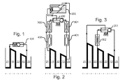
- Fig. 1 shows a portion of a gas turbine compressor according to an embodiment of the present invention in meridian section with an upstream (left in Fig. 1 ) Compressor stage with the playpen 11 and the upstream Leitgitter 21 and a downstream (right in Fig. 1 ) Compressor stage with the playpen 12 and the downstream of him Leitgitter 23 and arranged between two stages Leitgitter 22, wherein an axis of rotation of the compressor rotor carrying the playpens 11, 12, indicated by dash-dotted lines.
- a Umblaspassage is formed, which communicates exemplary in the exemplary embodiment radially outside and in the axial direction in front of the playpen 11 and behind the playpen 12 with the working fluid.
- the blowby passage can be at least partially integrally formed, for example, in a compressor housing or compressor rotor and / or defined by hose lines or the like.
- a biased check valve 100 which opens the bypass passage for the working fluid of the compressor, when the pressure of the downstream compressor stage exceeds the pressure of the upstream compressor stage by more than a predetermined value, which is predetermined by the biased compression spring of the check valve 100.
- the check valve 100 constitutes the sole processing member of a regulator for opening and closing the blowby passage by which the compressor pumps are reduced: the pressure difference between the upstream and downstream compressor stages falls below the value preset by the pressure spring, for example because the pressure in the upstream compressor stage drops too much or in the downstream compressor stage increases too much, ie the delivery height is increased too much, is automatically as long as working fluid at higher pressure from the downstream compressor stage through the Umblaspassage out to the upstream compressor stage, until the compressor operates again in the stable range.
- the processing member is actuated purely fluid-mechanically
- the controller operates fluidmechanically autonomous without power supply or control signals of a gas turbine controller. This can be reacted quickly and reliably, even in the event of a power failure, to, in particular transient, operating conditions of the compressor.
- the processing member fluidly links the two input variables "pressure of the downstream compressor stage” and “pressure of the upstream compressor stage” as a subtractor and compares them fluid mechanically with the value predetermined by the compression spring. It also acts as a detection member for detecting the two fluid mechanical variables “pressure of the downstream compressor stage” and “pressure of the upstream compressor stage” and as a fluid-mechanically actuated actuator that opens or closes the Umblaspassage.
- Fig. 2 shows in Fig. 1 corresponding representation of a part of a gas turbine compressor according to another embodiment of the present invention.
- Features consistent with the embodiment described above are designated by identical reference numerals, so that reference is made to the above embodiments and only to the differences from the embodiment according to Fig. 1 will be received.
- the controller is also purely fluidmechanical and autonomous, but more complex than in Fig. 1 In particular, it has a plurality of fluid-mechanically operable processing elements:
- Working fluid of the upstream compressor stage initially acts on a fluid-mechanical damper 400 and is then fed through a throttle 300 to a biased control valve 200.
- working fluid of the downstream compressor stage acts on a fluid-mechanical damper 401 and is supplied to the control valve 200 through a throttle 301.
- the biased control valve 200 is designed as a so-called “inverse shuttle valve”, as it is sold, for example, by The Lee Company (USA), to which reference is also made with respect to other fluidmechanisch operable processing elements. It is biased by a compression spring and formed so that it in the in Fig. 2 state, a fluid mechanically operable amplifier 500 with working fluid of the downstream compressor stage, which was passed through the damper 401 and the throttle 301, as long as the pressure of the downstream compressor stage after damper 401 and throttle 301, the pressure of the upstream compressor stage after damper 400 and throttle 300 to exceeds more than a predetermined value, which is predetermined by the prestressed compression spring of the control valve 200. This closes the booster 500, which in turn closes the blow-by passage between the upstream and downstream compressor stages.
- the booster 500 When this pressure difference drops below the value preset by the compression spring, for example, because the pressure in the upstream compressor stage falls too high or rises too much in the downstream compressor stage, i.e., the pressure drops too low. conversely, if the delivery head increases too much, the booster 500 is acted upon by working fluid of the upstream compressor stage which has passed through the damper 400 and the throttle 300. Accordingly, the booster 500 now opens the blow-by passage between the upstream and downstream compressor stages so that working fluid of higher pressure is automatically fed from the downstream compressor stage through the blow-by passage to the upstream compressor stage until the compressor operates again in the stable range.
- a fluid-mechanically autonomous multi-stage controller By the fluid-mechanically linked or interconnected, in turn fluid-mechanically operable processing members 200, 300, 301, 400, 401 and 500, a fluid-mechanically autonomous multi-stage controller is implemented.
- the dampers 400, 401, the throttles 300, 301, the vote in particular of the springs and / or surfaces of the control valve 200 and / or amplifier 500 the controlled system, which is implemented by this controller, are optimally tuned to the performance of the gas turbine compressor ,
- FIG. 3 shows in Fig. 1, 2 corresponding representation of a part of a gas turbine compressor according to another embodiment of the present invention.
- Features consistent with the embodiments described above are designated by identical reference numerals, so that reference is made to the above embodiments and only to the differences from the embodiments according to Fig. 1, 2 will be received.
- a middle compressor stage with a playpen 10 and an upstream guide grid 20 is arranged.
- a control valve 201 is biased by a compression spring and configured to be in the in Fig. 3 shown state a Umblaspassage between the downstream compressor stage with the playpen 12 and the downstream guide grid 23 and the upstream compressor stage with the playpen 11 and the upstream guide grid 21 blocks, as long as the pressure of the downstream compressor stage the pressure of the middle compressor stage with the playpen 10 and the upstream of him Leitgitter 20 after a throttle 302 by more than a predetermined value, which is predetermined by the prestressed compression spring of the control valve 201.
- the control valve 201 now opens the blow-by passage between the upstream and downstream compressor stages so that the higher pressure working fluid is automatically led from the downstream compressor stage through the blow-by passage to the upstream compressor stage until the compressor operates again in the stable range , By injecting working fluid from the downstream compressor stage into the upstream compressor stage, in particular, a compressor pump in the middle compressor stage is prevented or reduced, which results from a drop in the pressure difference between the middle and downstream compressor stage.
Landscapes
- Engineering & Computer Science (AREA)
- Mechanical Engineering (AREA)
- General Engineering & Computer Science (AREA)
- Life Sciences & Earth Sciences (AREA)
- Sustainable Development (AREA)
- Structures Of Non-Positive Displacement Pumps (AREA)
- Control Of Positive-Displacement Air Blowers (AREA)
Abstract
Description
- Die vorliegende Erfindung betrifft ein Verfahren und einen Regler zum Reduzieren eines Verdichterpumpens in einem Gasturbinenverdichter.
- Das Verdichterkennfeld eines Gasturbinenverdichters wird durch die sogenannte Pumpgrenze in einen stabilen und einen instabilen Bereich geteilt. Liegt, insbesondere durch Verminderung der Fördermenge oder Anstieg der Förderhöhe, der Betriebspunkt des Verdichters in dem instabilen Bereich, kann Arbeitsfluid entgegen der Förderrichtung des Verdichters, insbesondere zyklisch, in eine stromaufwärtige Stufe zurückströmen und von dieser wieder gefördert werden. Durch dieses sogenannte (Verdichter)Pumpen kann die Gasturbine belastet werden.
- Aus betriebsinterner Praxis ist eine Pumpverhütungs- bzw. Pumpschutzregelung bekannt, die auf Basis des Betriebspunkts des Verdichters bei Annäherung an die Pumpgrenze bzw. infolge eines Pumpdruckstoßes ein Entlastungsventil öffnet. Solche Pumpverhütungs- und Pumpschutzregelungen arbeiten elektronisch und werden extern durch einen Gasturbinenregler gesteuert. Diese ausfallsicher auszubilden, ist, insbesondere bei den hohen Sicherheitsanforderungen von Flugtriebwerken, aufwändig.
- Aufgabe der vorliegenden Erfindung ist es, Verdichterpumpen in einem Gasturbinenverdichter in vorteilhafter Weise zu reduzieren, insbesondere zu verhindern.
- Zur Lösung dieser Aufgabe ist ein Gasturbinenverdichter nach dem Oberbegriff des Anspruchs 1 durch dessen kennzeichnende Merkmale weitergebildet. Anspruch 11 stellt ein Verfahren zum Betrieb eines solchen Gasturbinenverdichters unter Schutz, die Unteransprüche betreffen vorteilhafte Weiterbildungen.
- Nach einem Aspekt der vorliegenden Erfindung weist ein Gasturbinenverdichter, insbesondere ein Flugtriebwerkverdichter, zwei oder mehrere Verdichterstufen sowie eine oder mehrere Umblaspassagen zur Rückführung von Arbeitsfluid von einer oder mehreren stromabwärtigeren zu einer oder mehreren stromaufwärtigeren Stufen, und einen Regler zum Öffnen und Schließen dieser Umblaspassage(n), um ein Verdichterpumpen zu reduzieren, insbesondere zu verhindern, auf.
- Durch eine ganz oder teilweise geöffnete Umblaspassage kann Arbeitsfluid von einer oder mehreren stromabwärtigen Stufen zu einer oder mehreren stromaufwärtigen Stufen strömen. In einer Ausführung kann eine Umblaspassage zwei, insbesondere benachbarte bzw. aufeinanderfolgende, Verdichterstufen verbinden. Zusätzlich oder alternativ können eine oder mehrere weitere Umblaspassagen dieselbe und/oder eine andere stromabwärtige Stufe mit derselben und/oder einer anderen stromaufwärtige Stufe verbinden.
- Der Regler kann dazu ausgebildet sein, eine oder mehrere Umblaspassagen, insbesondere gekoppelt bzw. synchron, zu öffnen und zu schließen.
- In einer Ausführung kann der Regler eine oder mehrere Umblaspassagen ausschließlich vollständig öffnen bzw. schließen. In einer anderen Ausführung kann der Regler eine oder mehrere Umblaspassagen auch teilweise öffnen bzw. schließen, insbesondere in vorgegebenen diskreten Schritten oder kontinuierlich.
- Eine oder mehrere Umblaspassagen können in axialer Richtung vor, bei oder nach einem Laufgitter einer Verdichterstufe in diese münden, vorzugsweise radial außen oder innen.
- Der Regler weist ein oder mehrere fluidmechanisch betätigbare Verarbeitungsglieder auf. Ein oder mehrere Verarbeitungsglieder sind in einer Ausführung durch das Arbeitsfluid pneumatisch betätigbar. Zusätzlich oder alternativ können ein oder mehrere Verarbeitungsglieder durch ein anderes Fluid betätigbar sein.
- Unter einem fluidmechanisch betätigbaren Verarbeitungsglied im Sinne der vorliegenden Erfindung wird insbesondere ein Bauteil verstanden, dass eine oder mehrere Eingangsgrößen in logischer und/oder arithmetischer Weise fluidmechanisch auf eine oder mehrere Ausgangsgrößen, insbesondere eine Stellgröße, abbildet, insbesondere zwei oder mehrere Eingangsgrößen fluidmechanisch miteinander verknüpft bzw. verschaltet. Zwei oder mehr Verarbeitungsglieder können ihrerseits fluidmechanisch miteinander verknüpft bzw. verschaltet sein, indem eine oder mehrere Ausgangsgrößen eines Verarbeitungsgliedes als Eingangsgröße(n) einem anderen Verarbeitungsglied fluidmechanisch zugeführt werden. "Fluidmechanisch" im Sinne der vorliegenden Erfindung kann insbesondere "mechanisch durch ein Fluid" bedeuten.
- Indem ein oder mehrere, vorzugsweise alle Verarbeitungsglieder des Reglers nicht elektronisch sondern fluidmechanisch betätigbar ausgebildet sind, kann auf einfache Weise ein zuverlässiger Regler zum Reduzieren eines Gasturbinenverdichterpumpens zur Verfügung gestellt werden.
- Das bzw. die Verarbeitungsglieder des Reglers bilden dessen Regelstrecke bzw. verknüpfen in einer oder mehreren durch je ein Verarbeitungsglied implementierten Stufen eine oder mehrere Regeleingänge, insbesondere fluidmechanische Größen, vorzugsweise Druck und/oder Volumenstrom, des Arbeitsmediums, insbesondere einer oder mehrerer stromaufwärtiger Verdichterstufen, zu einer oder mehreren Stellgrößen, die insbesondere ein Öffnen bzw. Schließen der Umblaspassage(n) bewirken. Dementsprechend kann ein Verarbeitungsglied im Sinne der vorliegenden Erfindung auch ein durch das Arbeitsmedium einer oder mehrerer Verdichterstufen fluidmechanisch beaufschlagtes Erfassungsglied und/oder ein fluidmechanisch betätigtes Stellglied zum Öffnen bzw. Schließen der Umblaspassage(n) aufweisen. Beispielsweise bildet ein federbelastetes Rückschlagventil in einer Umblaspassage ein fluidmechanisch betätigbares Verarbeitungsglied, das von dem Arbeitsfluid der stromabwärtigen Stufe beaufschlagt wird (Erfassungsglied) und dessen Druck mit der Federvorspannung derart regelungstechnisch verknüpft ist, dass bei einem Überschreiten eines - durch die Federvorspannung vorgegebenen - Wertes die Umblaspassage geöffnet bzw. bei Unterschreiten dieses Wertes geschlossen wird (Stellglied).
- In einer Ausführung ist der Regler fluidmechanisch ausgebildet. Hierunter wird insbesondere verstanden, dass der Regler rein fluidmechanisch arbeitet, d.h. seine gesamte Regelstrecke von der bzw. den Eingangsgrößen bis zu dem bzw. den Stelleingriffen, die die Umblaspassage(n) öffnen bzw. schließen, ausschließlich fluidmechanisch, insbesondere durch das Arbeitsfluid des Verdichters pneumatisch, implementiert ist, ohne dass der Regler elektronische Signale zum Regeln verwendet. Hierdurch kann der Regler insbesondere bei Stromausfall weiterarbeiten. Zusätzlich oder alternativ kann der Regler autonom ausgebildet sein. Hierunter wird insbesondere verstanden, dass der Regler nur auf Basis des Arbeitsfluids, insbesondere in einer oder mehreren stromaufwärtigen Stufen, als Eingangsgrößen regelt, bzw. dass der Regler nur auf Basis einer oder mehrerer fluidmechanischer Größen einer oder mehrerer Verdichterstufen arbeitet.
- In einer Ausführung weisen ein oder mehrere Verarbeitungsglieder des Reglers einen oder mehrere fluidmechanische, insbesondere pneumatische, Addierer, Subtrahierer, Vergleicher, Integratoren, Differenzierer, Dämpfer, Filter und/oder Begrenzer auf. Dabei wird unter einem Filter insbesondere ein Mittel verstanden, welches regelungstechnisch als Filter fungiert und vorgegebene Frequenzen einer fluidmechanischen Größe dämpft. Zusätzlich oder alternativ kann ein Filter auch ein Mittel sein, welches strömungstechnisch als Filter fungiert und Fremdstoffe einer vorgegebenen Größe aus dem Fluid entfernt, mit dem der Regler betätigt wird. Insbesondere kann ein Filter hierzu ein oder mehrere Siebe, Netze oder dergleichen aufweisen.
- Zusätzlich oder alternativ können ein oder mehrere Verarbeitungsglieder des Reglers einen oder mehrere fluidmechanische, insbesondere pneumatische, Speicher, insbesondere Durchschnitts- und/oder Extremalwertspeicher, aufweisen. Hierdurch kann vorteilhafterweise der Betriebsverlauf des Gasturbinenverdichters dokumentiert und/oder ausgewertet werden.
- Zusätzlich oder alternativ können ein oder mehrere Verarbeitungsglieder des Reglers einen oder mehrere fluidmechanisch betätigbare Ventile, insbesondere, vorzugsweise vorgespannte, Rückschlag- oder Stellventile aufweisen. Unter einem Ventil wird vorliegend insbesondere ein Mittel verstanden, durch das eine Fluidpassage vergrößert bzw. geöffnet und/oder verkleinert bzw. geschlossen werden kann, unter einem Rückschlagventil entsprechend ein Mittel, das ein Durchströmen einer Fluidpassage nur in einer Strömungsrichtung gestattet.
- In einer Ausführung ist der Regler temperaturabhängig regelnd ausgebildet. Hierzu kann er beispielsweise eine oder mehrere temperaturabhängige Ventile aufweisen, die bei Erreichen einer vorgegebenen Temperatur öffnen oder schließen.
- In einer Ausführung ist der Regler zur Ausgabe eines elektrischen Signals, insbesondere an einen elektronischen Gasturbinenregler, ausgebildet. Auch ein solcher Regler kann autonom im Sinne der vorliegenden Erfindung arbeiten, sofern er nur elektrische Signale ausgibt bzw. eingehende elektrische Signale keinen Einfluss auf die durch ihn implementierte Regelstrecke haben.
- Weitere Merkmale und Vorteile ergeben sich aus den Unteransprüchen und den Ausführungsbeispielen. Hierzu zeigt, teilweise schematisiert:
- Fig. 1:
- einen Teil eines Gasturbinenverdichters nach einer Ausführung der vorliegenden Erfindung im Meridianschnitt;
- Fig. 2:
- einen Teil eines Gasturbinenverdichters nach einer weiteren Ausführung der vorliegenden Erfindung in
Fig. 1 entsprechender Darstellung; und - Fig. 3:
- einen Teil eines Gasturbinenverdichters nach einer weiteren Ausführung der vorliegenden Erfindung in
Fig. 1, 2 entsprechender Darstellung. -
Fig. 1 zeigt einen Teil eines Gasturbinenverdichters nach einer Ausführung der vorliegenden Erfindung im Meridianschnitt mit einer stromaufwärtigen (links inFig. 1 ) Verdichterstufe mit dem Laufgitter 11 und dem ihm vorgelagerten Leitgitter 21 und einer stromabwärtigen (rechts inFig. 1 ) Verdichterstufe mit dem Laufgitter 12 und dem ihm nachgelagerten Leitgitter 23 sowie einem zwischen beiden Stufen angeordneten Leitgitter 22, wobei eine Drehachse des Verdichterrotors, der die Laufgitter 11, 12 trägt, strichpunktiert angedeutet ist. - Zwischen der stromaufwärtigen und der stromabwärtigen Verdichterstufe ist eine Umblaspassage ausgebildet, die im Ausführungsbeispiel exemplarisch radial außen und in Axialrichtung vor dem Laufgitter 11 bzw. hinter dem Laufgitter 12 mit dem Arbeitsfluid kommuniziert. Die Umblaspassage kann beispielsweise in einem Verdichtergehäuse oder Verdichterrotor wenigstens teilweise integral ausgebildet und/oder durch Schlauchleitungen oder dergleichen definiert sein.
- In der Umblaspassage ist ein vorgespanntes Rückschlagventil 100 angeordnet, das die Umblaspassage für das Arbeitsfluid des Verdichters öffnet, wenn der Druck der stromabwärtigen Verdichterstufe den Druck der stromaufwärtigen Verdichterstufe um mehr als einen vorgegebenen Wert überschreitet, der durch die vorgespannte Druckfeder des Rückschlagventils 100 vorgegeben ist.
- Das Rückschlagventil 100 bildet das einzige Verarbeitungsglied eines Reglers zum Öffnen und Schließen der Umblaspassage, durch den Verdichterpumpen reduziert wird: sinkt die Druckdifferenz zwischen stromauf- und stromabwärtiger Verdichterstufe unter den durch die Druckfeder vorgegebenen Wert, da beispielsweise der Druck in der stromaufwärtigen Verdichterstufe zu stark absinkt oder in der stromabwärtigen Verdichterstufe zu stark ansteigt, d.h. die Förderhöhe sich zu stark erhöht, wird selbsttätig solange Arbeitsfluid mit höherem Druck von der stromabwärtigen Verdichterstufe durch die Umblaspassage zu der stromaufwärtigen Verdichterstufe geführt, bis der Verdichter wieder im stabilen Bereich arbeitet.
- Dabei wird das Verarbeitungsglied rein fluidmechanisch betätigt, der Regler arbeitet fluidmechanisch autonom ohne Stromversorgung oder Steuersignale eines Gasturbinenreglers. Hierdurch kann schnell und zuverlässig, auch bei Stromausfall, auf, insbesondere transiente, Betriebszustände des Verdichters reagiert werden.
- Das Verarbeitungsglied verknüpft die beiden Eingangsgrößen "Druck der stromabwärtigen Verdichterstufe" und "Druck der stromaufwärtigen Verdichterstufe" fluidmechanisch als Subtrahierer und vergleicht sie fluidmechanisch mit dem durch die Druckfeder vorgegebenen Wert. Es fungiert zusätzlich als Erfassungsglied zur Erfassung der beiden fluidmechanischen Größen "Druck der stromabwärtigen Verdichterstufe" und "Druck der stromaufwärtigen Verdichterstufe" und als fluidmechanisch betätigtes Stellglied, das die Umblaspassage öffnet bzw. schließt.
-
Fig. 2 zeigt inFig. 1 entsprechender Darstellung einen Teil eines Gasturbinenverdichters nach einer weiteren Ausführung der vorliegenden Erfindung. Mit der vorstehend beschriebenen Ausführung übereinstimmende Merkmale sind durch identische Bezugszeichen bezeichnet, so dass auf die obigen Ausführungen Bezug genommen und nachfolgend nur auf die Unterschiede zur Ausführung nachFig. 1 eingegangen wird. - In
Fig. 2 ist der Regler ebenfalls rein fluidmechanisch und autonom ausgebildet, jedoch komplexer als inFig. 1 , insbesondere weist er mehrere fluidmechanisch betätigbare Verarbeitungsglieder auf: Arbeitsfluid der stromaufwärtigen Verdichterstufe beaufschlagt zunächst einen fluidmechanischen Dämpfer 400 und wird anschließend durch eine Drossel 300 einem vorgespannten Stellventil 200 zugeführt. Analog beaufschlagt Arbeitsfluid der stromabwärtigen Verdichterstufe einen fluidmechanischen Dämpfer 401 und wird durch eine Drossel 301 dem Stellventil 200 zugeführt. - Das vorgespannte Stellventil 200 ist als sogenanntes "inverse shuttle valve" ausgebildet, wie es beispielsweise von der Firma The Lee Company (USA) vertrieben wird, auf die auch bezüglich anderer fluidmechanisch betätigbarer Verarbeitungsglieder ergänzend verwiesen wird. Es ist durch eine Druckfeder vorgespannt und derart ausgebildet, dass es in dem in
Fig. 2 dargestellten Zustand einen fluidmechanisch betätigbaren Verstärker 500 mit Arbeitsfluid der stromabwärtigen Verdichterstufe beaufschlagt, das durch den Dämpfer 401 und die Drossel 301 geführt wurde, solange der Druck der stromabwärtigen Verdichterstufe nach Dämpfer 401 und Drossel 301 den Druck der stromaufwärtigen Verdichterstufe nach Dämpfer 400 und Drossel 300 um mehr als einen vorgegebenen Wert überschreitet, der durch die vorgespannte Druckfeder des Stellventils 200 vorgegeben ist. Hierdurch wird der Verstärker 500 geschlossen, der seinerseits die Umblaspassage zwischen stromaufwärtiger und stromabwärtiger Verdichterstufe schließt. - Sinkt diese Druckdifferenz unter den durch die Druckfeder vorgegebenen Wert, da beispielsweise der Druck in der stromaufwärtigen Verdichterstufe zu stark absinkt oder in der stromabwärtigen Verdichterstufe zu stark ansteigt, d.h. die Förderhöhe sich zu stark erhöht, wird umgekehrt der Verstärker 500 mit Arbeitsfluid der stromaufwärtigen Verdichterstufe beaufschlagt, das durch den Dämpfer 400 und die Drossel 300 geführt wurde. Entsprechend öffnet der Verstärker 500 nun die Umblaspassage zwischen stromaufwärtiger und stromabwärtiger Verdichterstufe, so dass selbsttätig solange Arbeitsfluid mit höherem Druck von der stromabwärtigen Verdichterstufe durch die Umblaspassage zu der stromaufwärtigen Verdichterstufe geführt wird, bis der Verdichter wieder im stabilen Bereich arbeitet.
- Durch die miteinander fluidmechanisch verknüpft bzw. verschalteten, ihrerseits fluidmechanisch betätigbaren Verarbeitungsglieder 200, 300, 301, 400, 401 und 500 ist ein fluidmechanisch autonomer mehrstufiger Regler implementiert. Dabei kann durch die Dämpfer 400, 401, die Drosseln 300, 301, die Abstimmung insbesondere der Federn und/oder Flächen des Stellventils 200 und/oder Verstärkers 500 die Regelstrecke, die durch diesen Regler implementiert ist, optimal auf das Betriebsverhalten des Gasturbinenverdichters abgestimmt werden.
-
Fig. 3 zeigt inFig. 1, 2 entsprechender Darstellung einen Teil eines Gasturbinenverdichters nach einer weiteren Ausführung der vorliegenden Erfindung. Mit den vorstehend beschriebenen Ausführungen übereinstimmende Merkmale sind durch identische Bezugszeichen bezeichnet, so dass auf die obigen Ausführungen Bezug genommen und nachfolgend nur auf die Unterschiede zu den Ausführungen nachFig. 1, 2 eingegangen wird. - In der Ausführung nach
Fig. 3 ist zwischen der stromabwärtigen Verdichterstufe mit dem Laufgitter 12 und dem ihm nachgelagerten Leitgitter 23 und der stromaufwärtigen Verdichterstufe mit dem Laufgitter 11 und dem ihm vorgelagerten Leitgitter 21 außer dem Leitgitter 22 eine mittlere Verdichterstufe mit einem Laufgitter 10 und einem ihm vorgelagerten Leitgitter 20 angeordnet. - Ein Stellventil 201 ist durch eine Druckfeder vorgespannt und derart ausgebildet, dass es in dem in
Fig. 3 dargestellten Zustand eine Umblaspassage zwischen der stromabwärtigen Verdichterstufe mit dem Laufgitter 12 und dem ihm nachgelagerten Leitgitter 23 und der stromaufwärtigen Verdichterstufe mit dem Laufgitter 11 und dem ihm vorgelagerten Leitgitter 21 sperrt, solange der Druck der stromabwärtigen Verdichterstufe den Druck der mittleren Verdichterstufe mit dem Laufgitter 10 und dem ihm vorgelagerten Leitgitter 20 nach einer Drossel 302 um mehr als einen vorgegebenen Wert überschreitet, der durch die vorgespannte Druckfeder des Stellventils 201 vorgegeben ist. - Sinkt diese Druckdifferenz unter den durch die Druckfeder vorgegebenen Wert, da beispielsweise der Druck in der mittleren Verdichterstufe zu stark absinkt oder in der stromabwärtigen Verdichterstufe zu stark ansteigt, d.h. die Förderhöhe sich zu stark erhöht, öffnet das Stellventil 201 nun die Umblaspassage zwischen stromaufwärtigen und stromabwärtiger Verdichterstufe, so dass selbsttätig solange Arbeitsfluid mit höherem Druck von der stromabwärtigen Verdichterstufe durch die Umblaspassage zu der stromaufwärtigen Verdichterstufe geführt wird, bis der Verdichter wieder im stabilen Bereich arbeitet. Durch das Einblasen von Arbeitsfluid von der stromabwärtiger Verdichterstufe in die stromaufwärtige Verdichterstufe wird insbesondere ein Verdichterpumpen in der mittleren Verdichterstufe verhindert oder reduziert, das aus einem Abfall der Druckdifferenz zwischen mittlerer und stromabwärtiger Verdichterstufe resultiert.
-
- 10, 11, 12
- Laufgitter
- 20,21,22,23
- Leitgitter
- 100
- vorgespanntes Rückschlagventil
- 200; 201
- vorgespanntes Stellventil ("shuttle valve")
- 300, 301; 302
- Drossel
- 400, 401
- fluidmechanischer Dämpfer
- 500
- fluidmechanischer Verstärker
Claims (11)
- Gasturbinenverdichter, insbesondere Flugtriebwerkverdichter, mit wenigstens zwei Verdichterstufen (10, 11, 12), einer Umblaspassage zur Rückführung von Arbeitsfluid von einer stromabwärtigen zu einer stromaufwärtigen Stufe, und einem Regler zum Öffnen und Schließen der Umblaspassage, um ein Verdichterpumpen zu reduzieren, dadurch gekennzeichnet, dass
der Regler wenigstens ein, insbesondere durch das Arbeitsfluid, fluidmechanisch betätigbares Verarbeitungsglied (100; 200, 300, 301, 400, 401, 500; 201, 302) aufweist. - Gasturbinenverdichter nach Anspruch 1, dadurch gekennzeichnet, dass der Regler fluidmechanisch autonom ausgebildet ist.
- Gasturbinenverdichter nach einem der vorhergehenden Ansprüche, dadurch gekennzeichnet, dass der Regler zur Erfassung und fluidmechanischen Verarbeitung wenigstens einer fluidmechanischen Größe wenigstens einer Verdichterstufe ausgebildet ist.
- Gasturbinenverdichter nach einem der vorhergehenden Ansprüche, dadurch gekennzeichnet, dass der Regler einen fluidmechanischen Addierer, Subtrahierer, Vergleicher, Integrator, Differenzierer, Dämpfer (400, 401), Filter und/oder Begrenzer aufweist.
- Gasturbinenverdichter nach einem der vorhergehenden Ansprüche, dadurch gekennzeichnet, dass der Regler einen fluidmechanischen Speicher, insbesondere einen Durchschnitts- und/oder Extremalwertspeicher, aufweist.
- Gasturbinenverdichter nach einem der vorhergehenden Ansprüche, dadurch gekennzeichnet, dass der Regler ein fluidmechanisch betätigbares Ventil, insbesondere ein, insbesondere vorgespanntes, Rückschlag- oder Stellventil (100; 200; 201) und/oder eine Drossel (300, 301; 302) aufweist.
- Gasturbinenverdichter nach einem der vorhergehenden Ansprüche, gekennzeichnet durch eine durch den Regler öffen- und schließbare Umblaspassage zur Rückführung von Arbeitsfluid von einer stromabwärtigen (12) zu einer dieser benachbarten stromaufwärtigen Stufe (11).
- Gasturbinenverdichter nach einem der vorhergehenden Ansprüche, gekennzeichnet durch eine durch den Regler öffen- und schließbare Umblaspassage zur Rückführung von Arbeitsfluid von einer stromabwärtigen (12) zu einer stromaufwärtigen Stufe (11), wobei der Regler durch Arbeitsfluid einer zwischen dieser stromabwärtigen und stromaufwärtigen Stufe (11, 12) angeordneten mittleren Stufe (10) betätigt wird.
- Gasturbinenverdichter nach einem der vorhergehenden Ansprüche, dadurch gekennzeichnet, dass der Regler temperaturabhängig regelnd ausgebildet ist.
- Gasturbinenverdichter nach einem der vorhergehenden Ansprüche, dadurch gekennzeichnet, dass der Regler zur Ausgabe eines elektrischen Signals, insbesondere an einen elektronischen Gasturbinenregler, ausgebildet ist.
- Verfahren zum Reduzieren eines Verdichterpumpens in einem Gasturbinenverdichter nach einem der vorhergehenden Ansprüche, dadurch gekennzeichnet, dass der Regler fluidmechanisch autonom arbeitet.
Priority Applications (1)
| Application Number | Priority Date | Filing Date | Title |
|---|---|---|---|
| EP12179977.9A EP2696077B1 (de) | 2012-08-10 | 2012-08-10 | Gasturbinenverdichter mit reduziertem Pumpen sowie zugehöriges Verfahren |
Applications Claiming Priority (1)
| Application Number | Priority Date | Filing Date | Title |
|---|---|---|---|
| EP12179977.9A EP2696077B1 (de) | 2012-08-10 | 2012-08-10 | Gasturbinenverdichter mit reduziertem Pumpen sowie zugehöriges Verfahren |
Publications (2)
| Publication Number | Publication Date |
|---|---|
| EP2696077A1 true EP2696077A1 (de) | 2014-02-12 |
| EP2696077B1 EP2696077B1 (de) | 2015-07-29 |
Family
ID=46967916
Family Applications (1)
| Application Number | Title | Priority Date | Filing Date |
|---|---|---|---|
| EP12179977.9A Not-in-force EP2696077B1 (de) | 2012-08-10 | 2012-08-10 | Gasturbinenverdichter mit reduziertem Pumpen sowie zugehöriges Verfahren |
Country Status (1)
| Country | Link |
|---|---|
| EP (1) | EP2696077B1 (de) |
Cited By (1)
| Publication number | Priority date | Publication date | Assignee | Title |
|---|---|---|---|---|
| GB2575270A (en) * | 2018-07-03 | 2020-01-08 | Edwards Ltd | Interstage valve |
Citations (4)
| Publication number | Priority date | Publication date | Assignee | Title |
|---|---|---|---|---|
| US2837269A (en) * | 1954-05-03 | 1958-06-03 | United Aircraft Corp | Compressor bleed control |
| US3073511A (en) * | 1959-05-18 | 1963-01-15 | Garrett Corp | Temperature compensated compressor bleed control mechanism |
| DE2853340A1 (de) * | 1977-12-13 | 1979-07-05 | Pratt & Whitney Aircraft | Vorrichtung zum erzeugen eines vorwirbels am verdichtereingang eines turbinen-triebwerkes |
| DE102004055439A1 (de) * | 2004-11-17 | 2006-05-24 | Rolls-Royce Deutschland Ltd & Co Kg | Strömungsarbeitsmaschine mit dynamischer Strömungsbeeinflussung |
-
2012
- 2012-08-10 EP EP12179977.9A patent/EP2696077B1/de not_active Not-in-force
Patent Citations (4)
| Publication number | Priority date | Publication date | Assignee | Title |
|---|---|---|---|---|
| US2837269A (en) * | 1954-05-03 | 1958-06-03 | United Aircraft Corp | Compressor bleed control |
| US3073511A (en) * | 1959-05-18 | 1963-01-15 | Garrett Corp | Temperature compensated compressor bleed control mechanism |
| DE2853340A1 (de) * | 1977-12-13 | 1979-07-05 | Pratt & Whitney Aircraft | Vorrichtung zum erzeugen eines vorwirbels am verdichtereingang eines turbinen-triebwerkes |
| DE102004055439A1 (de) * | 2004-11-17 | 2006-05-24 | Rolls-Royce Deutschland Ltd & Co Kg | Strömungsarbeitsmaschine mit dynamischer Strömungsbeeinflussung |
Cited By (1)
| Publication number | Priority date | Publication date | Assignee | Title |
|---|---|---|---|---|
| GB2575270A (en) * | 2018-07-03 | 2020-01-08 | Edwards Ltd | Interstage valve |
Also Published As
| Publication number | Publication date |
|---|---|
| EP2696077B1 (de) | 2015-07-29 |
Similar Documents
| Publication | Publication Date | Title |
|---|---|---|
| DE4416572C1 (de) | Aufgeladene Brennkraftmaschine | |
| EP2010760B1 (de) | Entlüftungseinrichtung für eine aufgeladene brennkraftmaschine | |
| EP2419644B1 (de) | Mehrstufiger turboverdichter | |
| EP1134422A2 (de) | Verfahren zur Regulierung des Pumpens eines Turbokompressors | |
| DE102014114397A1 (de) | Brennkraftmaschine mit einer Kurbelgehäuseentlüftungseinrichtung und Verfahren zum Überwachen einer Kurbelgehäuseentlüftungseinrichtung | |
| EP1916396A1 (de) | Registeraufladeeinrichtung | |
| DE102010004657A1 (de) | Frischgasversorgungsvorrichtung für eine Verbrennungsmaschine und Verfahren zum Betrieb einer solchen Frischgasversorgungsvorrichtung | |
| DE102014217591A1 (de) | Verfahren und Vorrichtung zur Ansteuerung eines Abgasrückführventils einer aufgeladenen Brennkraftmaschine mit Abgasrückführung | |
| DE2746485C2 (de) | Regeleinrichtung für eine Abblas- oder Abzapfeinrichtung in Turbomaschinen | |
| DE19860639A1 (de) | Verfahren zum Betreiben eines Kompressors mit nachgeschaltetem Verbraucher, und nach dem Verfahren arbeitende Anlage | |
| DE3032218A1 (de) | Kolbenbrennkraftmaschine mit einem abgasturbolader | |
| DE3246483C2 (de) | Steuereinrichtung für ein Turbinen-Bypaß-Ventil eines abgasturbogeladenen Brennkraftmotors | |
| DE102010040503A1 (de) | Verfahren zur Steuerung eines Verdichters | |
| DE102011003019A1 (de) | Partikelfilter und Verfahren zur Reinigung eines Abgasstroms | |
| DE102014221049A1 (de) | Anordnung und Verfahren zum Abblasen von Verdichterluft in einem Triebwerk | |
| DE102014220742B4 (de) | Verfahren zum Betreiben eines Kraftstoffversorgungssystems für eine Brennkraftmaschine | |
| EP2696077B1 (de) | Gasturbinenverdichter mit reduziertem Pumpen sowie zugehöriges Verfahren | |
| DE102012209357B4 (de) | Verfahren und Vorrichtung zur Diagnose eines Schubumluftventils für eine Aufladeeinrichtung eines Verbrennungsmotors | |
| EP3183446B1 (de) | Kompressoreinheit und verfahren zu deren betrieb | |
| DE102014223845A1 (de) | Verdichter für einen Abgasturbolader | |
| EP3101242B1 (de) | Unterdruckerzeugung im kurbelgehäuse zur partikelzahlreduzierung | |
| DE102008054764A1 (de) | Verfahren und Vorrichtung zur Diagnose eines pneumatischen Schubumluftventils einer Aufladevorrichtung eines Verbrennungsmotors | |
| DE60223881T2 (de) | Verfahren und Einrichtung zur Regelung des Luftstromes in einem Ansaugkrümmer einer Brennkraftmaschine eines Kraftfahrzeuges | |
| DE102017202292A1 (de) | Entlüftungssystem für ein Kurbelgehäuse eines Verbrennungsmotors | |
| DE102005007558A1 (de) | Verfahren und Anordnung zum Schützen eines Turboladers in einem Fahrzeug gegen Überdrehen |
Legal Events
| Date | Code | Title | Description |
|---|---|---|---|
| AK | Designated contracting states |
Kind code of ref document: A1 Designated state(s): AL AT BE BG CH CY CZ DE DK EE ES FI FR GB GR HR HU IE IS IT LI LT LU LV MC MK MT NL NO PL PT RO RS SE SI SK SM TR |
|
| AX | Request for extension of the european patent |
Extension state: BA ME |
|
| PUAI | Public reference made under article 153(3) epc to a published international application that has entered the european phase |
Free format text: ORIGINAL CODE: 0009012 |
|
| 17P | Request for examination filed |
Effective date: 20140714 |
|
| RBV | Designated contracting states (corrected) |
Designated state(s): AL AT BE BG CH CY CZ DE DK EE ES FI FR GB GR HR HU IE IS IT LI LT LU LV MC MK MT NL NO PL PT RO RS SE SI SK SM TR |
|
| RAP1 | Party data changed (applicant data changed or rights of an application transferred) |
Owner name: MTU AERO ENGINES GMBH |
|
| GRAP | Despatch of communication of intention to grant a patent |
Free format text: ORIGINAL CODE: EPIDOSNIGR1 |
|
| INTG | Intention to grant announced |
Effective date: 20150401 |
|
| GRAS | Grant fee paid |
Free format text: ORIGINAL CODE: EPIDOSNIGR3 |
|
| GRAA | (expected) grant |
Free format text: ORIGINAL CODE: 0009210 |
|
| RAP1 | Party data changed (applicant data changed or rights of an application transferred) |
Owner name: MTU AERO ENGINES AG |
|
| AK | Designated contracting states |
Kind code of ref document: B1 Designated state(s): AL AT BE BG CH CY CZ DE DK EE ES FI FR GB GR HR HU IE IS IT LI LT LU LV MC MK MT NL NO PL PT RO RS SE SI SK SM TR |
|
| REG | Reference to a national code |
Ref country code: GB Ref legal event code: FG4D Free format text: NOT ENGLISH |
|
| REG | Reference to a national code |
Ref country code: CH Ref legal event code: EP |
|
| REG | Reference to a national code |
Ref country code: AT Ref legal event code: REF Ref document number: 739545 Country of ref document: AT Kind code of ref document: T Effective date: 20150815 |
|
| REG | Reference to a national code |
Ref country code: IE Ref legal event code: FG4D Free format text: LANGUAGE OF EP DOCUMENT: GERMAN |
|
| REG | Reference to a national code |
Ref country code: DE Ref legal event code: R096 Ref document number: 502012003909 Country of ref document: DE |
|
| REG | Reference to a national code |
Ref country code: LT Ref legal event code: MG4D |
|
| REG | Reference to a national code |
Ref country code: NL Ref legal event code: MP Effective date: 20150729 |
|
| PG25 | Lapsed in a contracting state [announced via postgrant information from national office to epo] |
Ref country code: GR Free format text: LAPSE BECAUSE OF FAILURE TO SUBMIT A TRANSLATION OF THE DESCRIPTION OR TO PAY THE FEE WITHIN THE PRESCRIBED TIME-LIMIT Effective date: 20151030 Ref country code: LT Free format text: LAPSE BECAUSE OF FAILURE TO SUBMIT A TRANSLATION OF THE DESCRIPTION OR TO PAY THE FEE WITHIN THE PRESCRIBED TIME-LIMIT Effective date: 20150729 Ref country code: NO Free format text: LAPSE BECAUSE OF FAILURE TO SUBMIT A TRANSLATION OF THE DESCRIPTION OR TO PAY THE FEE WITHIN THE PRESCRIBED TIME-LIMIT Effective date: 20151029 Ref country code: FI Free format text: LAPSE BECAUSE OF FAILURE TO SUBMIT A TRANSLATION OF THE DESCRIPTION OR TO PAY THE FEE WITHIN THE PRESCRIBED TIME-LIMIT Effective date: 20150729 Ref country code: LV Free format text: LAPSE BECAUSE OF FAILURE TO SUBMIT A TRANSLATION OF THE DESCRIPTION OR TO PAY THE FEE WITHIN THE PRESCRIBED TIME-LIMIT Effective date: 20150729 |
|
| PG25 | Lapsed in a contracting state [announced via postgrant information from national office to epo] |
Ref country code: SE Free format text: LAPSE BECAUSE OF FAILURE TO SUBMIT A TRANSLATION OF THE DESCRIPTION OR TO PAY THE FEE WITHIN THE PRESCRIBED TIME-LIMIT Effective date: 20150729 Ref country code: PT Free format text: LAPSE BECAUSE OF FAILURE TO SUBMIT A TRANSLATION OF THE DESCRIPTION OR TO PAY THE FEE WITHIN THE PRESCRIBED TIME-LIMIT Effective date: 20151130 Ref country code: RS Free format text: LAPSE BECAUSE OF FAILURE TO SUBMIT A TRANSLATION OF THE DESCRIPTION OR TO PAY THE FEE WITHIN THE PRESCRIBED TIME-LIMIT Effective date: 20150729 Ref country code: IS Free format text: LAPSE BECAUSE OF FAILURE TO SUBMIT A TRANSLATION OF THE DESCRIPTION OR TO PAY THE FEE WITHIN THE PRESCRIBED TIME-LIMIT Effective date: 20151129 Ref country code: HR Free format text: LAPSE BECAUSE OF FAILURE TO SUBMIT A TRANSLATION OF THE DESCRIPTION OR TO PAY THE FEE WITHIN THE PRESCRIBED TIME-LIMIT Effective date: 20150729 Ref country code: PL Free format text: LAPSE BECAUSE OF FAILURE TO SUBMIT A TRANSLATION OF THE DESCRIPTION OR TO PAY THE FEE WITHIN THE PRESCRIBED TIME-LIMIT Effective date: 20150729 Ref country code: ES Free format text: LAPSE BECAUSE OF FAILURE TO SUBMIT A TRANSLATION OF THE DESCRIPTION OR TO PAY THE FEE WITHIN THE PRESCRIBED TIME-LIMIT Effective date: 20150729 |
|
| PG25 | Lapsed in a contracting state [announced via postgrant information from national office to epo] |
Ref country code: NL Free format text: LAPSE BECAUSE OF FAILURE TO SUBMIT A TRANSLATION OF THE DESCRIPTION OR TO PAY THE FEE WITHIN THE PRESCRIBED TIME-LIMIT Effective date: 20150729 |
|
| REG | Reference to a national code |
Ref country code: CH Ref legal event code: PL |
|
| PG25 | Lapsed in a contracting state [announced via postgrant information from national office to epo] |
Ref country code: DK Free format text: LAPSE BECAUSE OF FAILURE TO SUBMIT A TRANSLATION OF THE DESCRIPTION OR TO PAY THE FEE WITHIN THE PRESCRIBED TIME-LIMIT Effective date: 20150729 Ref country code: SK Free format text: LAPSE BECAUSE OF FAILURE TO SUBMIT A TRANSLATION OF THE DESCRIPTION OR TO PAY THE FEE WITHIN THE PRESCRIBED TIME-LIMIT Effective date: 20150729 Ref country code: CZ Free format text: LAPSE BECAUSE OF FAILURE TO SUBMIT A TRANSLATION OF THE DESCRIPTION OR TO PAY THE FEE WITHIN THE PRESCRIBED TIME-LIMIT Effective date: 20150729 Ref country code: CH Free format text: LAPSE BECAUSE OF NON-PAYMENT OF DUE FEES Effective date: 20150831 Ref country code: IT Free format text: LAPSE BECAUSE OF FAILURE TO SUBMIT A TRANSLATION OF THE DESCRIPTION OR TO PAY THE FEE WITHIN THE PRESCRIBED TIME-LIMIT Effective date: 20150729 Ref country code: LI Free format text: LAPSE BECAUSE OF NON-PAYMENT OF DUE FEES Effective date: 20150831 Ref country code: EE Free format text: LAPSE BECAUSE OF FAILURE TO SUBMIT A TRANSLATION OF THE DESCRIPTION OR TO PAY THE FEE WITHIN THE PRESCRIBED TIME-LIMIT Effective date: 20150729 Ref country code: MC Free format text: LAPSE BECAUSE OF FAILURE TO SUBMIT A TRANSLATION OF THE DESCRIPTION OR TO PAY THE FEE WITHIN THE PRESCRIBED TIME-LIMIT Effective date: 20150729 |
|
| REG | Reference to a national code |
Ref country code: DE Ref legal event code: R097 Ref document number: 502012003909 Country of ref document: DE |
|
| PG25 | Lapsed in a contracting state [announced via postgrant information from national office to epo] |
Ref country code: RO Free format text: LAPSE BECAUSE OF FAILURE TO SUBMIT A TRANSLATION OF THE DESCRIPTION OR TO PAY THE FEE WITHIN THE PRESCRIBED TIME-LIMIT Effective date: 20150729 |
|
| REG | Reference to a national code |
Ref country code: IE Ref legal event code: MM4A |
|
| PLBE | No opposition filed within time limit |
Free format text: ORIGINAL CODE: 0009261 |
|
| STAA | Information on the status of an ep patent application or granted ep patent |
Free format text: STATUS: NO OPPOSITION FILED WITHIN TIME LIMIT |
|
| 26N | No opposition filed |
Effective date: 20160502 |
|
| PG25 | Lapsed in a contracting state [announced via postgrant information from national office to epo] |
Ref country code: IE Free format text: LAPSE BECAUSE OF NON-PAYMENT OF DUE FEES Effective date: 20150810 |
|
| REG | Reference to a national code |
Ref country code: FR Ref legal event code: PLFP Year of fee payment: 5 |
|
| PG25 | Lapsed in a contracting state [announced via postgrant information from national office to epo] |
Ref country code: SI Free format text: LAPSE BECAUSE OF FAILURE TO SUBMIT A TRANSLATION OF THE DESCRIPTION OR TO PAY THE FEE WITHIN THE PRESCRIBED TIME-LIMIT Effective date: 20150729 |
|
| PGFP | Annual fee paid to national office [announced via postgrant information from national office to epo] |
Ref country code: GB Payment date: 20160824 Year of fee payment: 5 Ref country code: DE Payment date: 20160823 Year of fee payment: 5 |
|
| PGFP | Annual fee paid to national office [announced via postgrant information from national office to epo] |
Ref country code: FR Payment date: 20160825 Year of fee payment: 5 |
|
| PG25 | Lapsed in a contracting state [announced via postgrant information from national office to epo] |
Ref country code: MT Free format text: LAPSE BECAUSE OF FAILURE TO SUBMIT A TRANSLATION OF THE DESCRIPTION OR TO PAY THE FEE WITHIN THE PRESCRIBED TIME-LIMIT Effective date: 20150729 |
|
| PG25 | Lapsed in a contracting state [announced via postgrant information from national office to epo] |
Ref country code: SM Free format text: LAPSE BECAUSE OF FAILURE TO SUBMIT A TRANSLATION OF THE DESCRIPTION OR TO PAY THE FEE WITHIN THE PRESCRIBED TIME-LIMIT Effective date: 20150729 Ref country code: HU Free format text: LAPSE BECAUSE OF FAILURE TO SUBMIT A TRANSLATION OF THE DESCRIPTION OR TO PAY THE FEE WITHIN THE PRESCRIBED TIME-LIMIT; INVALID AB INITIO Effective date: 20120810 Ref country code: BG Free format text: LAPSE BECAUSE OF FAILURE TO SUBMIT A TRANSLATION OF THE DESCRIPTION OR TO PAY THE FEE WITHIN THE PRESCRIBED TIME-LIMIT Effective date: 20150729 |
|
| PG25 | Lapsed in a contracting state [announced via postgrant information from national office to epo] |
Ref country code: CY Free format text: LAPSE BECAUSE OF FAILURE TO SUBMIT A TRANSLATION OF THE DESCRIPTION OR TO PAY THE FEE WITHIN THE PRESCRIBED TIME-LIMIT Effective date: 20150729 |
|
| PG25 | Lapsed in a contracting state [announced via postgrant information from national office to epo] |
Ref country code: BE Free format text: LAPSE BECAUSE OF NON-PAYMENT OF DUE FEES Effective date: 20150831 |
|
| PG25 | Lapsed in a contracting state [announced via postgrant information from national office to epo] |
Ref country code: LU Free format text: LAPSE BECAUSE OF NON-PAYMENT OF DUE FEES Effective date: 20150810 |
|
| REG | Reference to a national code |
Ref country code: DE Ref legal event code: R119 Ref document number: 502012003909 Country of ref document: DE |
|
| GBPC | Gb: european patent ceased through non-payment of renewal fee |
Effective date: 20170810 |
|
| REG | Reference to a national code |
Ref country code: FR Ref legal event code: ST Effective date: 20180430 |
|
| PG25 | Lapsed in a contracting state [announced via postgrant information from national office to epo] |
Ref country code: TR Free format text: LAPSE BECAUSE OF FAILURE TO SUBMIT A TRANSLATION OF THE DESCRIPTION OR TO PAY THE FEE WITHIN THE PRESCRIBED TIME-LIMIT Effective date: 20150729 Ref country code: MK Free format text: LAPSE BECAUSE OF FAILURE TO SUBMIT A TRANSLATION OF THE DESCRIPTION OR TO PAY THE FEE WITHIN THE PRESCRIBED TIME-LIMIT Effective date: 20150729 |
|
| PG25 | Lapsed in a contracting state [announced via postgrant information from national office to epo] |
Ref country code: GB Free format text: LAPSE BECAUSE OF NON-PAYMENT OF DUE FEES Effective date: 20170810 Ref country code: DE Free format text: LAPSE BECAUSE OF NON-PAYMENT OF DUE FEES Effective date: 20180301 |
|
| PG25 | Lapsed in a contracting state [announced via postgrant information from national office to epo] |
Ref country code: FR Free format text: LAPSE BECAUSE OF NON-PAYMENT OF DUE FEES Effective date: 20170831 |
|
| REG | Reference to a national code |
Ref country code: AT Ref legal event code: MM01 Ref document number: 739545 Country of ref document: AT Kind code of ref document: T Effective date: 20170810 |
|
| PG25 | Lapsed in a contracting state [announced via postgrant information from national office to epo] |
Ref country code: AL Free format text: LAPSE BECAUSE OF FAILURE TO SUBMIT A TRANSLATION OF THE DESCRIPTION OR TO PAY THE FEE WITHIN THE PRESCRIBED TIME-LIMIT Effective date: 20150729 |
|
| PG25 | Lapsed in a contracting state [announced via postgrant information from national office to epo] |
Ref country code: AT Free format text: LAPSE BECAUSE OF NON-PAYMENT OF DUE FEES Effective date: 20170810 |