EP2696074B1 - Improvements in and relating to diaphragm pumps - Google Patents
Improvements in and relating to diaphragm pumps Download PDFInfo
- Publication number
- EP2696074B1 EP2696074B1 EP13179767.2A EP13179767A EP2696074B1 EP 2696074 B1 EP2696074 B1 EP 2696074B1 EP 13179767 A EP13179767 A EP 13179767A EP 2696074 B1 EP2696074 B1 EP 2696074B1
- Authority
- EP
- European Patent Office
- Prior art keywords
- motor
- plate
- pump
- housing
- diaphragm
- Prior art date
- Legal status (The legal status is an assumption and is not a legal conclusion. Google has not performed a legal analysis and makes no representation as to the accuracy of the status listed.)
- Active
Links
Images









Classifications
-
- F—MECHANICAL ENGINEERING; LIGHTING; HEATING; WEAPONS; BLASTING
- F04—POSITIVE - DISPLACEMENT MACHINES FOR LIQUIDS; PUMPS FOR LIQUIDS OR ELASTIC FLUIDS
- F04B—POSITIVE-DISPLACEMENT MACHINES FOR LIQUIDS; PUMPS
- F04B43/00—Machines, pumps, or pumping installations having flexible working members
- F04B43/02—Machines, pumps, or pumping installations having flexible working members having plate-like flexible members, e.g. diaphragms
- F04B43/025—Machines, pumps, or pumping installations having flexible working members having plate-like flexible members, e.g. diaphragms two or more plate-like pumping members in parallel
- F04B43/026—Machines, pumps, or pumping installations having flexible working members having plate-like flexible members, e.g. diaphragms two or more plate-like pumping members in parallel each plate-like pumping flexible member working in its own pumping chamber
-
- F—MECHANICAL ENGINEERING; LIGHTING; HEATING; WEAPONS; BLASTING
- F04—POSITIVE - DISPLACEMENT MACHINES FOR LIQUIDS; PUMPS FOR LIQUIDS OR ELASTIC FLUIDS
- F04B—POSITIVE-DISPLACEMENT MACHINES FOR LIQUIDS; PUMPS
- F04B43/00—Machines, pumps, or pumping installations having flexible working members
- F04B43/02—Machines, pumps, or pumping installations having flexible working members having plate-like flexible members, e.g. diaphragms
- F04B43/04—Pumps having electric drive
-
- F—MECHANICAL ENGINEERING; LIGHTING; HEATING; WEAPONS; BLASTING
- F04—POSITIVE - DISPLACEMENT MACHINES FOR LIQUIDS; PUMPS FOR LIQUIDS OR ELASTIC FLUIDS
- F04B—POSITIVE-DISPLACEMENT MACHINES FOR LIQUIDS; PUMPS
- F04B39/00—Component parts, details, or accessories, of pumps or pumping systems specially adapted for elastic fluids, not otherwise provided for in, or of interest apart from, groups F04B25/00 - F04B37/00
- F04B39/12—Casings; Cylinders; Cylinder heads; Fluid connections
- F04B39/121—Casings
-
- F—MECHANICAL ENGINEERING; LIGHTING; HEATING; WEAPONS; BLASTING
- F04—POSITIVE - DISPLACEMENT MACHINES FOR LIQUIDS; PUMPS FOR LIQUIDS OR ELASTIC FLUIDS
- F04B—POSITIVE-DISPLACEMENT MACHINES FOR LIQUIDS; PUMPS
- F04B53/00—Component parts, details or accessories not provided for in, or of interest apart from, groups F04B1/00 - F04B23/00 or F04B39/00 - F04B47/00
- F04B53/16—Casings; Cylinders; Cylinder liners or heads; Fluid connections
-
- F—MECHANICAL ENGINEERING; LIGHTING; HEATING; WEAPONS; BLASTING
- F04—POSITIVE - DISPLACEMENT MACHINES FOR LIQUIDS; PUMPS FOR LIQUIDS OR ELASTIC FLUIDS
- F04B—POSITIVE-DISPLACEMENT MACHINES FOR LIQUIDS; PUMPS
- F04B9/00—Piston machines or pumps characterised by the driving or driven means to or from their working members
- F04B9/02—Piston machines or pumps characterised by the driving or driven means to or from their working members the means being mechanical
-
- F—MECHANICAL ENGINEERING; LIGHTING; HEATING; WEAPONS; BLASTING
- F04—POSITIVE - DISPLACEMENT MACHINES FOR LIQUIDS; PUMPS FOR LIQUIDS OR ELASTIC FLUIDS
- F04B—POSITIVE-DISPLACEMENT MACHINES FOR LIQUIDS; PUMPS
- F04B9/00—Piston machines or pumps characterised by the driving or driven means to or from their working members
- F04B9/02—Piston machines or pumps characterised by the driving or driven means to or from their working members the means being mechanical
- F04B9/04—Piston machines or pumps characterised by the driving or driven means to or from their working members the means being mechanical the means being cams, eccentrics or pin-and-slot mechanisms
- F04B9/042—Piston machines or pumps characterised by the driving or driven means to or from their working members the means being mechanical the means being cams, eccentrics or pin-and-slot mechanisms the means being cams
Definitions
- the present invention concerns improvements in and relating to diaphragm pumps.
- United Kingdom Patent Specification No. GB 2 352 779 B and European Patent Specification No. EP 1 222 392 B disclose a diaphragm pump comprising a two-part casing formed of a front cover and a back cover; and a diaphragm plate extending across the covers and being secured therebetween when the covers are fastened together.
- the diaphragm plate has a plurality of circular regions.
- the front cover has substantially axially aligned inlet and outlet ports, each leading to mutually exclusively inlet and outlet chambers.
- valve housing securable inside the front cover and having defined therein an outlet dished valve seat with a correspondingly concave resilient outlet valve seated therein, the outlet dished valve seat having fluid passages therethrough, and a plurality of inlet valve seats, equal in number to the number of circular regions on the diaphragm plate, each inlet valve seat being similarly dished and having a correspondingly concave resilient valve seated therein, each inlet valve seat having fluid passages therethrough, the resilient outlet valve being in fluid communication with the outlet chamber and each said inlet valve being in fluid communication with the inlet chamber.
- the diaphragm pump also includes a wobble plate positioned in the back cover; the wobble plate has a central boss and a plurality of similar piston sections equal in number to the number of circular regions on the diaphragm plate, the piston sections and circular regions being correspondingly secured together, the wobble plate being subject to nutating motion to cause reciprocating action by the circular regions on the diaphragm plate and provide a pumping action.
- the present invention relates to improvements to the diaphragm pump disclosed in GB 2 352 779 B and EP 1 222 392 B and provides technical advantages over the previously known diaphragm pumps.
- the present invention accordingly provides a diaphragm pump comprising a housing for receiving and securely holding a motor, the housing comprising an elongate portion having a closed end and an open end, the elongate portion being adapted to securely receive and house a motor; and a collar portion being provided at the open end of the elongate portion; a cover for the housing, the cover being adapted to engage with the housing; a diaphragm plate extending across the open end of the housing between the collar portion of the housing and the cover and being secured therebetween when the cover is engaged with the collar portion of the housing; the diaphragm pump comprising a motor locking plate adapted to be secured to the motor such that when the motor locking plate is secured to the motor and with the motor inserted in the elongate portion of the housing, at least a portion of the motor locking plate is provided within the collar portion of the housing; the diaphragm plate having a plurality of similarly defined circular regions the cover having substantially axially aligned inlet and outlet ports each leading to mutual
- diaphragm pumps required a two-part casing including a front cover and a rear cover between which covers, a diaphragm plate extended and the diaphragm cover was secured between the covers.
- the diaphragm pump of the present invention has an advantage that only one cover is required and the motor is securely housed within an integrally formed motor housing having a collar portion at an open end of the housing, the collar portion being adapted for sealingly engaging with the cover. This has the advantage that only the cover is required to seal the open end of the motor housing.
- the elongate main body of the housing is provided with a plurality of elongate ribs provided at spaced apart locations on the inside walls of the elongate main body and extending along substantially the length of the elongate main body.
- the motor locking plate comprises an engagement lug for engaging with the wobble plate and optionally, wherein a plurality of radially extending ribs extend from around the engagement lug.
- the engagement lug is adapted for engagement with the wobble plate such that the drive shaft of the motor is engaged with a bearing on the wobble plate to drive the nutating action of the wobble plate so as to cause movement of the circular portions of the diaphragm plate.
- the motor locking plate ideally also comprises an enclosure for receiving and housing a switch whereby an integral pressure switch can be provided on the motor locking plate.
- the motor locking plate advantageously also comprises a barrel for receiving a spiral spring and plunger.
- the plunger ideally includes an arm operable for pressing on the micro-switch when the plunger is pressed inwardly so as to activate the micro-switch and thereby activating the motor.
- the plunger may be of different lengths so as to pre-set the maximum pressure of the pump to a pre-determined setting.
- the motor housing is beneficially adapted to receive and house a motor of a relatively short dimension or a relatively longer dimension.
- the diaphragm support plate for supporting the diaphragm plate is provided in the collar portion of the housing, the diaphragm support plate having an equal number of similar apertures corresponding to the number of circular regions on the diaphragm plate each aperture having a walled surround, the circular regions of the diaphragm plate fitting into respective apertures in the diaphragm support plate and being supported thereby.
- the circular regions of the diaphragm plate are each provided with an outstanding lug formation and the mating surfaces of the piston sections of the wobble plate are provided with complimentary shaped slots, the securement being formed when the lug formation of each circular region is engaged in the slot of the corresponding piston section.
- the lug formation of each diaphragm and the slot of each corresponding piston section is beneficially of cruciform shape.
- the outer ends of the lug formation are preferably of greater length than the slots to provide a locking means in the slots.
- a diaphragm support plate may be provided, the support plate having an equal number of similar apertures corresponding to the number of circular regions on the diaphragm plate, each aperture on the diaphragm support plate having a walled surround, the circular regions on the diaphragm plate fitting into respective apertures of the diaphragm support plate and being supported thereby.
- the housing preferably has a series of mounting feet fitted thereto, some of the feet being substantially ovoid in plan; and optionally at least one of the feet being substantially circular in cross-section.
- the feet are formed of resilient material.
- the diaphragm plate is provided with a further defined circular region which is smaller than the other plurality of defined circular regions; and the diaphragm support plate has a similarly shaped aperture with wall surround to accommodate a micro-switch activated by movement of the further circular region serving as a pressure switch pad, the electrical wires to the micro-switch being fed internally from the front face of the motor.
- the valve housing is preferably provided, on the same side as the inlet valve seats are positioned, with a track leading from a hole exiting on that side and centrally provided in the outlet valve seat provided on the opposite side, the track mating with a corresponding track provided on the diaphragm plate, the mated tracks forming a passage between the hole and the further circular region whereby any fluid leaving the outlet chamber, when under pressure through the screw, travels along the passage and fills a void at the pressure pad on the opposite side of the diaphragm plate from the pressure switch causing activation of the micro-switch to stop the pump.
- valve housing is fixed to the cover by a fixing means such as a screw.
- the at least one valve seat has a corresponding concave resilient valve seated therein and preferably, the pump has a plurality of inlet valve seats, equal in number to the number of circular regions on the diaphragm plate, each inlet valve seat having a corresponding concave resilient valve seated therein, each inlet valve seat having fluid passages therethrough.
- a diaphragm pump in accordance with the present invention is indicated generally by reference number 100 and comprises a housing 101 and a cover 10 adapted to securably engage with the housing 101.
- the diaphragm pump 100 comprises the motor housing 101 for receiving a motor M and a motor locking plate 200 engageably attached to the motor M by fastening means comprising four screws 201.
- the motor locking plate 200 can be secured to the housing 101 by fastening means comprising three screws 202.
- the motor housing 101 comprises an elongate main body 105 having a closed end 106 and an open end 107. At the open end 107, the housing 101 is provided with a collar portion 110 which is adapted to engage with a cover 10 shown in Figures 8A and 8B .
- the collar portion 110 has upstanding walls 120 having ribs 125, 125' for providing a seal when the cover 10 is engaged with the collar portion 110.
- the ribs 125, 125' also provide structural support to the collar portion 110.
- the elongate main body 105 of the housing 101 is provided with a plurality of elongate ribs 115 provided at spaced apart locations on the inside walls of the elongate main body 105 and extending along substantially the length of the elongate main body 105.
- the ribs 115 are adapted to absorb the torque from the motor M, when the motor is located in the elongate main body 105 and when the motor has been activated and is operating in use.
- the ribs 115 tend to grip the motor M as the motor vibrates when in use. Torque is transmitted by the motor and tends to force the motor to turn. The tendency of the motor to turn forces the motor to engage against the ribs 115 and thereby lock the motor more securely in the housing 101.
- the ribs 115 have the effect of ensuring that the motor is not abutting against the inside walls of housing 101 so that the walls of the motor are spaced apart from the major face of the inside walls of the elongate main body 105. Because of this spacing apart function of the ribs 115, there is a layer of air between the motor and the major face of the inside walls of the elongate main body 105 of the housing 101. This assists cooling of the motor because of more effective heat dissipation from the motor when in use.
- the diaphragm pump 100 also includes a motor locking plate 200 which is adapted to be secured to the motor M.
- the motor locking plate 200 comprises a lug 205 from which radiate a plurality of radially extending ribs 206 for providing structural strength to the motor locking plate 200.
- the lug 205 is for structural support.
- the drive shaft DS of the motor is engaged with a bearing 54 on the wobble plate 40 to drive the nutating action of the wobble plate 40 so as to cause movement of the circular portions 16 of the diaphragm plate 14.
- the motor locking plate 200 also comprises an enclosure 202 for receiving and housing a micro-switch 302.
- the motor locking plate 200 also comprises a barrel for receiving a spiral spring 301 and plunger 303.
- the plunger 303 includes an arm 304 for pressing on the micro-switch when the plunger is pressed inwardly so as to activate the micro-switch 302 and thereby activating the motor M.
- the motor locking plate 200 has two setting such that the motor locking plate has a control function.
- the pressure switch location and operation is supported by the locking plate design.
- a diaphragm plate 14 extends across the open mouth of the collar portion 110 and is located between the collar portion 110 and the cover 10 and is sealingly secured therebetween when the cover 10 is engaged with the housing by fixing means such as the three screws.
- the diaphragm plate 14 has a plurality of four similarly defined circular regions 16.
- the cover 10 has substantially axially aligned inlet and outlet ports 18, 20, each leading to mutually exclusive inlet and outlet chambers 22, 24, respectively.
- the outlet chamber 24 is provided centrally of the cover 10 and has a wall surround 25 through which the outlet port 20 communicates.
- the inlet chamber 22 is defined between the wall surround 25 and a wall of the cover 10.
- a valve housing 26 is substantially planar and is secured inside the front cover 10 and has defined therein on one side, four outlet valve seats 28 with a correspondingly resilient valve 30 seated in each valve seat 28.
- the outlet valve seats 28 have a plurality of holes 32 forming fluid passages therethrough; and the outlet valve seats 28 are arranged about a central hole 72.
- the four outlet valve seats 28 are in fluid communication with the outlet chamber 24; and the inlet valve seats 34 are in fluid communication with the inlet chamber 22.
- Each valve 36 is formed of a dished, part-spherical portion having a post 35 radially outstanding from its rear face, the post having a bulbous portion 37, the valve being seated by the post 35 being pushed through the hole 72, 73 respectively with the bulbous portion 37 holding the valve in position preventing unintentional removal.
- a wobble plate 40 is positioned within the collar portion 110 of the housing 101.
- the wobble plate has a central boss 42 and a plurality of four similar piston sections 44.
- the piston sections 44 and circular regions 16 are correspondingly secured together.
- the wobble plate 40 is subject to nutating motion, like 'four cylinders', to cause reciprocating action by the circular regions 16 of the diaphragm plate 14 sequentially and provide a pumping action.
- the circular regions 16 of the diaphragm plate 14 are each provided with an outstanding lug formation 46 and the mating surfaces of the piston sections 44 of the wobble plate 40 are provided with complementary shaped slots 48. The securement between them is formed when the lug formation 46 of each circular region 16 is engaged in the slot 48 of the corresponding piston section 44.
- the lug formation 46 of each circular region 16 diaphragm plate 14 and the slot 48 of each corresponding piston section 44 is of cruciform shape.
- the outer ends of the lug formation 46 are of greater length that the slots 48 to provide a locking means with the slots 48.
- a diaphragm support plate 50 is adapted to engage with the collar portion 110 of the motor housing such that the diaphragm support plate 50 engages with the upstanding walls of the collar portion 110; and the diaphragm plate 14 is engaged on the diaphragm support plate 50 so that the assembled diaphragm support plate 50 together with the diaphragm plate 14 form a seal between the collar portion 110 and the cover 10 when assembled and fixed together by fixing means such as screws.
- the diaphragm support plate 50 has four apertures 52 which are similar to each other. Each aperture 52 has a walled surround with the circular regions 16 fitting into respective apertures 52.
- the boss 42 of the wobble plate 40 seats and holds by an inwardly-extending retaining flange 56 a bearing 54 having a ball race, the bearing 54 preferably having been insert moulded in the boss 42.
- the electric motor 76 drive shaft DS is connected to the bearing 54 via the lug 205 provided on the motor locking plate 200.
- the lug 205 has radially extending ribs 206 for strengthening the motor locking plate 200.
- the engagement lug 205 fits into the wobble plate 40 with the drive shaft of the motor engaging the bearing 54.
- the housing 101 has a plurality of mounting feet 150, 155 fitted thereto, the feet 150 are each being substantially ovoid in plan and feet 155 is circular.
- the feet 150, 155 are of resilient material to dampen vibratory movement.
- the two feet 150 are similarly provided with two fixing holes at their narrower end and being capable of rotating in and about their respective mating slot.
- a single foot 155 which is generally circular in cross-section is provided towards the closed end of the housing.
- the valve housing 26 is fixed to the cover 10 by a screw (not shown).
- An integral pressure switch (not shown) is provided in the back cover 12 with the diaphragm plate 14 being provided with a fifth defined circular region 66, smaller than the other regions 16, the rear of the diaphragm support plate 50 having a similarly shaped aperture 68 with wall surround to accommodate the circular region 66.
- a micro-switch is retained in an enclosure 82 on the back cover 12 by an upstand 80 in the diaphragm support plate 50 is activated by movement of the fifth circular region 66 serving as a pressure switch pad, the electrical wires to the micro-switch being fed internally from the front face of the motor.
- the mated tracks 70, 74 form a passage between the hole 72 and the fifth circular region 66 whereby any fluid leaving the outlet chamber 24 when under pressure through the screw travels along the passage and fills a void at the pressure pad on the opposite side of the diaphragm plate 14 from the pressure switch causing activation of the micro-switch to stop the pump.
- Figures 15A and 15B show a first embodiment of a plunger; and referring to Figures 16A and 16B which show a second embodiment of a plunger, the function of the plunger 303, 303' will be described.
- the length of the plunger 303 determines the pressure of the pump. Therefore, the available pressure of the pump is pre-determined at the design and manufacturing stage rather than by the end user. The motor therefore is operated within its optimum range of power and is more likely to have a longer life span.
- the length of the plunger 303, 303' determines the pressure setting of the diaphragm pump 100.
- a shorter length plunger 303 as shown in Figures 15A and 15B determines that the pressure of the pump will be at a lower setting i.e. 2 bar pressure.
- a longer length plunger as shown in Figures 16A and 16B determines that the pressure will be at a higher setting, i.e. 3 bar.
- At one end of the plunger 303 is the circular region 16 of the diaphragm plate 14 while at the other end of the plunger is the spiral spring against which the plunger 303 presses as it is pressed downwardly in the barrel 203 on the motor locking plate 200.
- the longer plunger 303' exerts more of a force on the circular region 16 of the diaphragm plate 14 and therefore the pressure exerted by the pump 10 will be higher (i.e. at 3 bar rather than 2 bar).
- the diaphragm pump 100 can be switched on to pump, in an even flow, fluid, normally water, from the supply source.
- the motor M drives the wobble plate 40 to nutate and reciprocate the piston sections and circular regions of the diaphragm plate in a pumping action so as to operate the diaphragm pump 100.
- One of the advantages of the improved diaphragm pump 100 is that there is only one seal involved between the motor housing 110 and the cover 10 whereas previously there were two seals which had to be achieved in the prior art two-part casings.
Landscapes
- Engineering & Computer Science (AREA)
- Mechanical Engineering (AREA)
- General Engineering & Computer Science (AREA)
- Reciprocating Pumps (AREA)
Description
- The present invention concerns improvements in and relating to diaphragm pumps.
- United Kingdom Patent Specification No.
GB 2 352 779 B EP 1 222 392 B - The present invention relates to improvements to the diaphragm pump disclosed in
GB 2 352 779 B EP 1 222 392 B - The present invention accordingly provides a diaphragm pump comprising a housing for receiving and securely holding a motor, the housing comprising an elongate portion having a closed end and an open end, the elongate portion being adapted to securely receive and house a motor; and a collar portion being provided at the open end of the elongate portion; a cover for the housing, the cover being adapted to engage with the housing; a diaphragm plate extending across the open end of the housing between the collar portion of the housing and the cover and being secured therebetween when the cover is engaged with the collar portion of the housing; the diaphragm pump comprising a motor locking plate adapted to be secured to the motor such that when the motor locking plate is secured to the motor and with the motor inserted in the elongate portion of the housing, at least a portion of the motor locking plate is provided within the collar portion of the housing; the diaphragm plate having a plurality of similarly defined circular regions the cover having substantially axially aligned inlet and outlet ports each leading to mutually exclusive inlet and outlet chambers respectively, a valve housing securable inside the cover and having defined therein at least one outlet valve seat, the outlet valve seat being in fluid communication with the outlet chamber and the pump have at least one inlet valve seat the inlet valve seat being in fluid communication with the inlet chamber; and a wobble plate positioned within the collar portion of the housing, the wobble plate having a central boss and a plurality of similar piston sections equal in number to the number of circular regions on the diaphragm plate, the piston sections and circular regions on the diaphragm plate being correspondingly secured together, whereby in use, when the motor is activated, the wobble plate is subject to nutating motion to cause reciprocating action of the circular regions and thereby provide a pumping action.
- Heretofore, known diaphragm pumps required a two-part casing including a front cover and a rear cover between which covers, a diaphragm plate extended and the diaphragm cover was secured between the covers.
- The diaphragm pump of the present invention has an advantage that only one cover is required and the motor is securely housed within an integrally formed motor housing having a collar portion at an open end of the housing, the collar portion being adapted for sealingly engaging with the cover. This has the advantage that only the cover is required to seal the open end of the motor housing.
- Advantageously, the elongate main body of the housing is provided with a plurality of elongate ribs provided at spaced apart locations on the inside walls of the elongate main body and extending along substantially the length of the elongate main body.
- Ideally, the motor locking plate comprises an engagement lug for engaging with the wobble plate and optionally, wherein a plurality of radially extending ribs extend from around the engagement lug.
- Preferably, the engagement lug is adapted for engagement with the wobble plate such that the drive shaft of the motor is engaged with a bearing on the wobble plate to drive the nutating action of the wobble plate so as to cause movement of the circular portions of the diaphragm plate.
- The motor locking plate ideally also comprises an enclosure for receiving and housing a switch whereby an integral pressure switch can be provided on the motor locking plate.
- The motor locking plate advantageously also comprises a barrel for receiving a spiral spring and plunger.
- The plunger ideally includes an arm operable for pressing on the micro-switch when the plunger is pressed inwardly so as to activate the micro-switch and thereby activating the motor.
- Furthermore, the plunger may be of different lengths so as to pre-set the maximum pressure of the pump to a pre-determined setting.
- The motor housing is beneficially adapted to receive and house a motor of a relatively short dimension or a relatively longer dimension.
- Ideally, the diaphragm support plate for supporting the diaphragm plate is provided in the collar portion of the housing, the diaphragm support plate having an equal number of similar apertures corresponding to the number of circular regions on the diaphragm plate each aperture having a walled surround, the circular regions of the diaphragm plate fitting into respective apertures in the diaphragm support plate and being supported thereby.
- Preferably, the circular regions of the diaphragm plate are each provided with an outstanding lug formation and the mating surfaces of the piston sections of the wobble plate are provided with complimentary shaped slots, the securement being formed when the lug formation of each circular region is engaged in the slot of the corresponding piston section. The lug formation of each diaphragm and the slot of each corresponding piston section is beneficially of cruciform shape. The outer ends of the lug formation are preferably of greater length than the slots to provide a locking means in the slots. A diaphragm support plate may be provided, the support plate having an equal number of similar apertures corresponding to the number of circular regions on the diaphragm plate, each aperture on the diaphragm support plate having a walled surround, the circular regions on the diaphragm plate fitting into respective apertures of the diaphragm support plate and being supported thereby.
- The housing preferably has a series of mounting feet fitted thereto, some of the feet being substantially ovoid in plan; and optionally at least one of the feet being substantially circular in cross-section. The feet are formed of resilient material.
- The diaphragm plate is provided with a further defined circular region which is smaller than the other plurality of defined circular regions; and the diaphragm support plate has a similarly shaped aperture with wall surround to accommodate a micro-switch activated by movement of the further circular region serving as a pressure switch pad, the electrical wires to the micro-switch being fed internally from the front face of the motor.
- The valve housing is preferably provided, on the same side as the inlet valve seats are positioned, with a track leading from a hole exiting on that side and centrally provided in the outlet valve seat provided on the opposite side, the track mating with a corresponding track provided on the diaphragm plate, the mated tracks forming a passage between the hole and the further circular region whereby any fluid leaving the outlet chamber, when under pressure through the screw, travels along the passage and fills a void at the pressure pad on the opposite side of the diaphragm plate from the pressure switch causing activation of the micro-switch to stop the pump.
- Preferably further, the valve housing is fixed to the cover by a fixing means such as a screw.
- Advantageously, the at least one valve seat has a corresponding concave resilient valve seated therein and preferably, the pump has a plurality of inlet valve seats, equal in number to the number of circular regions on the diaphragm plate, each inlet valve seat having a corresponding concave resilient valve seated therein, each inlet valve seat having fluid passages therethrough.
- The improved diaphragm pump of the present invention will now be described more particularly, by way of example only, with reference to the accompanying drawings in which are shown a number of embodiments of the improved diaphragm pump of the present invention.
- In the drawings:
-
Figure 1 is a perspective view of the motor housing adapted for receiving and securely housing the motor; and the motor lock assembly comprising the motor and the motor locking plate; inFigure 1 , the motor locking plate is shown connected to the motor by four screws and connectable to the motor housing by three screws; -
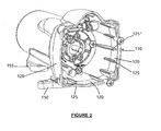
Figure 2 is a perspective view of the motor locking assembly comprising the motor and the motor locking plate inserted in the motor housing such that the motor is securely received and locked in the main body of the housing i.e. the elongate portion of the housing; and with the motor locking plate being located within the collar portion of the housing; the motor locking plate being securable to the housing by fixing means, preferably, three screws; -
Figure 3 is a perspective view of the motor housing with the motor and the motor locking plate secured and locked in the motor housing; -
Figure 4 is a side sectional view ofFigure 3 with the motor and motor locking plate within the motor housing; -
Figure 5 is an exploded view (without the motor housing) of the motor the motor locking plate, a switch, a spiral spring and plunger; and four screws for securing the motor locking plate to the motor; -
Figure 6 is a perspective view of the motor and motor locking plate connected together by the four screws; and showing the micro-switch located within an enclosure provided in the motor locking plate, for the micro-switch and showing the spiral spring and plunger received within the plunger barrel located adjacent to the micro-switch housing on the motor locking plate; -
Figure 7A is a side sectional view of the assembled motor and motor locking plate shown inFigure 6 with the plunger shown out of engagement with the micro-switch; -
Figure 7B is a side sectional view of the assembled motor and motor locking plate shown inFigure 6 as forFigure 7A but now with the plunger shown in contact with the micro switch to activate the micro-switch so as to turn on the motor; -
Figures 8A and 8B are perspective views from above and from below the cover for the motor housing which is engaged with the motor housing to encase the component parts and to form the assembled diaphragm pump of the present invention; -
Figures 9A and 9B are respectively perspective views from above and from below of a valve housing of the diaphragm pump; -
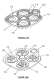
Figures 10A and 10B are, respectively, perspective views from above and from below of a diaphragm plate of the pump; -
Figures 11A and 11B are, respectively, perspective views from above and from below of a diaphragm support plate of the pump; -
Figures 12A, 12B and 12C are, respectively, a perspective view from above, a perspective view from below, and a cross-sectional view of a wobble plate of the pump; -
Figure 13 is an exploded view of the components to be assembled to form the diaphragm pump of the present invention; -
Figures 9A to 12C showing the valve housing, the diaphragm plate, the diaphragm support plate and the wobble plate include similar features as previously described inEP 1 222 392 -
Figure 14 is a perspective view of an assembled pump; and -
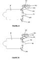
Figures 15A and 15B are side sectional views corresponding toFigures 7A and 7B but with the motor, motor locking plate; micro-switch within the micro-switch enclosure and the spiral spring and plunger within the plunger barrel, all shown located within the motor housing; -
Figures 16A and 16B are side sectional views of an alternative embodiment of that shown inFigures 15A and 15b , respectively, with a longer plunger being included in the embodiment ofFigures 16A and 16B ; -
Figures 17A, 17B and 17C show the ribs provided at spaced apart intervals along the inside of the motor housing; -
Figure 17A is a perspective view from underneath of the motor and motor housing locking plate located within the housing and also shows the feet of the diaphragm pump of the present invention; -
Figure 17B is an exploded view ofFigure 12A showing the detail of the ribs provided at spaced apart intervals and provided longitudinally along the length of the main body of the housing for abutting against the motor when the motor is inserted in the housing; -
Figure 17C is a plan view from the rear of the diaphragm pump showing the closed end of the motor housing and the feet of the diaphragm pump; -
Figure 17D is a sectional view taken of the motor housing and motor as shown inFigure 17C ; -
Figures 17E and 17F are further views corresponding toFigures 17A and 17B ; -
Figure 18 is a sectional view of the assembled diaphragm pump shown inFigure 14 ; -
Figure 19 is a sectional view of the assembled diaphragm pump an alternative embodiment with a longer motor being included in the motor housing than the motor shown inFigure 18 ; -
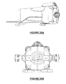
Figures 20A, 20B and20C respectively show the assembled diaphragm pump in accordance with the present invention mounted in a horizontal position; -
Figure 20A is a longitudinal side view of horizontally mounted pump; -
Figure 20B is a plan view of horizontally mounted pump; -
Figure 20C is a perspective view of horizontally mounted pump; -
Figures 21A, 21B and 21C respectively show the assembled diaphragm pump in accordance with the present invention mounted in a vertical position; -
Figure 21A is a perspective view of a vertically mounted assembled pump; -
Figure 21B is a side view from a first side of the vertically mounted assembled pump; and -
Figure 21C is a side view from a second side of the vertically mounted assembled pump. - Referring to the drawings, a diaphragm pump in accordance with the present invention is indicated generally by
reference number 100 and comprises ahousing 101 and acover 10 adapted to securably engage with thehousing 101. Thediaphragm pump 100 comprises themotor housing 101 for receiving a motor M and amotor locking plate 200 engageably attached to the motor M by fastening means comprising fourscrews 201. Themotor locking plate 200 can be secured to thehousing 101 by fastening means comprising threescrews 202. - The
motor housing 101 comprises an elongatemain body 105 having aclosed end 106 and anopen end 107. At theopen end 107, thehousing 101 is provided with acollar portion 110 which is adapted to engage with acover 10 shown inFigures 8A and 8B . Thecollar portion 110 hasupstanding walls 120 havingribs 125, 125' for providing a seal when thecover 10 is engaged with thecollar portion 110. Theribs 125, 125' also provide structural support to thecollar portion 110. - The elongate
main body 105 of thehousing 101 is provided with a plurality ofelongate ribs 115 provided at spaced apart locations on the inside walls of the elongatemain body 105 and extending along substantially the length of the elongatemain body 105. Theribs 115 are adapted to absorb the torque from the motor M, when the motor is located in the elongatemain body 105 and when the motor has been activated and is operating in use. - The
ribs 115 tend to grip the motor M as the motor vibrates when in use. Torque is transmitted by the motor and tends to force the motor to turn. The tendency of the motor to turn forces the motor to engage against theribs 115 and thereby lock the motor more securely in thehousing 101. - Furthermore, the
ribs 115 have the effect of ensuring that the motor is not abutting against the inside walls ofhousing 101 so that the walls of the motor are spaced apart from the major face of the inside walls of the elongatemain body 105. Because of this spacing apart function of theribs 115, there is a layer of air between the motor and the major face of the inside walls of the elongatemain body 105 of thehousing 101. This assists cooling of the motor because of more effective heat dissipation from the motor when in use. - The
diaphragm pump 100 also includes amotor locking plate 200 which is adapted to be secured to the motor M. Themotor locking plate 200 comprises alug 205 from which radiate a plurality of radially extendingribs 206 for providing structural strength to themotor locking plate 200. - The
lug 205 is for structural support. In use, the drive shaft DS of the motor is engaged with a bearing 54 on thewobble plate 40 to drive the nutating action of thewobble plate 40 so as to cause movement of thecircular portions 16 of thediaphragm plate 14. - The
motor locking plate 200 also comprises anenclosure 202 for receiving and housing amicro-switch 302. - Furthermore, the
motor locking plate 200 also comprises a barrel for receiving aspiral spring 301 andplunger 303. Theplunger 303 includes anarm 304 for pressing on the micro-switch when the plunger is pressed inwardly so as to activate themicro-switch 302 and thereby activating the motor M. - The
motor locking plate 200 has two setting such that the motor locking plate has a control function. The pressure switch location and operation is supported by the locking plate design. - A
diaphragm plate 14 extends across the open mouth of thecollar portion 110 and is located between thecollar portion 110 and thecover 10 and is sealingly secured therebetween when thecover 10 is engaged with the housing by fixing means such as the three screws. Thediaphragm plate 14 has a plurality of four similarly definedcircular regions 16. - The
cover 10 has substantially axially aligned inlet andoutlet ports outlet chambers outlet chamber 24 is provided centrally of thecover 10 and has awall surround 25 through which theoutlet port 20 communicates. Theinlet chamber 22 is defined between thewall surround 25 and a wall of thecover 10. - A
valve housing 26 is substantially planar and is secured inside thefront cover 10 and has defined therein on one side, four outlet valve seats 28 with a correspondinglyresilient valve 30 seated in eachvalve seat 28.. The outlet valve seats 28 have a plurality ofholes 32 forming fluid passages therethrough; and the outlet valve seats 28 are arranged about acentral hole 72. On the opposite side of thehousing 26, a plurality of four inlet valve seats 34 are provided, each having a correspondingly concaveresilient valve 36 seated therein, eachinlet valve seat 34 having arcuate griddedareas 38 forming fluid passages therethrough and a central hole 73. The four outlet valve seats 28 are in fluid communication with theoutlet chamber 24; and the inlet valve seats 34 are in fluid communication with theinlet chamber 22. Eachvalve 36 is formed of a dished, part-spherical portion having apost 35 radially outstanding from its rear face, the post having abulbous portion 37, the valve being seated by thepost 35 being pushed through thehole 72, 73 respectively with thebulbous portion 37 holding the valve in position preventing unintentional removal. - A
wobble plate 40 is positioned within thecollar portion 110 of thehousing 101. The wobble plate has acentral boss 42 and a plurality of foursimilar piston sections 44. Thepiston sections 44 andcircular regions 16 are correspondingly secured together. Thewobble plate 40 is subject to nutating motion, like 'four cylinders', to cause reciprocating action by thecircular regions 16 of thediaphragm plate 14 sequentially and provide a pumping action. - The
circular regions 16 of thediaphragm plate 14 are each provided with anoutstanding lug formation 46 and the mating surfaces of thepiston sections 44 of thewobble plate 40 are provided with complementary shapedslots 48. The securement between them is formed when thelug formation 46 of eachcircular region 16 is engaged in theslot 48 of thecorresponding piston section 44. Thelug formation 46 of eachcircular region 16diaphragm plate 14 and theslot 48 of eachcorresponding piston section 44 is of cruciform shape. The outer ends of thelug formation 46 are of greater length that theslots 48 to provide a locking means with theslots 48. - A
diaphragm support plate 50 is adapted to engage with thecollar portion 110 of the motor housing such that thediaphragm support plate 50 engages with the upstanding walls of thecollar portion 110; and thediaphragm plate 14 is engaged on thediaphragm support plate 50 so that the assembleddiaphragm support plate 50 together with thediaphragm plate 14 form a seal between thecollar portion 110 and thecover 10 when assembled and fixed together by fixing means such as screws. Thediaphragm support plate 50 has fourapertures 52 which are similar to each other. Eachaperture 52 has a walled surround with thecircular regions 16 fitting intorespective apertures 52. - The
boss 42 of thewobble plate 40 seats and holds by an inwardly-extending retaining flange 56 abearing 54 having a ball race, the bearing 54 preferably having been insert moulded in theboss 42. - The electric motor 76 drive shaft DS is connected to the
bearing 54 via thelug 205 provided on themotor locking plate 200. Thelug 205 has radially extendingribs 206 for strengthening themotor locking plate 200. Theengagement lug 205 fits into thewobble plate 40 with the drive shaft of the motor engaging thebearing 54. - The
housing 101 has a plurality of mountingfeet feet 150 are each being substantially ovoid in plan andfeet 155 is circular. Thefeet feet 150 are similarly provided with two fixing holes at their narrower end and being capable of rotating in and about their respective mating slot. Asingle foot 155 which is generally circular in cross-section is provided towards the closed end of the housing. - The
valve housing 26 is fixed to thecover 10 by a screw (not shown). An integral pressure switch (not shown) is provided in the back cover 12 with thediaphragm plate 14 being provided with a fifth definedcircular region 66, smaller than theother regions 16, the rear of thediaphragm support plate 50 having a similarly shapedaperture 68 with wall surround to accommodate thecircular region 66. A micro-switch is retained in an enclosure 82 on the back cover 12 by anupstand 80 in thediaphragm support plate 50 is activated by movement of the fifthcircular region 66 serving as a pressure switch pad, the electrical wires to the micro-switch being fed internally from the front face of the motor. Thevalve housing 26, on the same side as the inlet valve seats 34 are positioned, is provided with atrack 70 between two inlet valve seats 34 leading from thehole 72 exiting on that side and centrally provided between the outlet valve seats 28 provided on the opposite side, thetrack 70 mating with acorresponding track 74 provided on thediaphragm plate 14. The mated tracks 70, 74 form a passage between thehole 72 and the fifthcircular region 66 whereby any fluid leaving theoutlet chamber 24 when under pressure through the screw travels along the passage and fills a void at the pressure pad on the opposite side of thediaphragm plate 14 from the pressure switch causing activation of the micro-switch to stop the pump. - Referring now particularly to
Figures 15A and 15B , these Figures show a first embodiment of a plunger; and referring toFigures 16A and 16B which show a second embodiment of a plunger, the function of theplunger 303, 303' will be described. - The length of the
plunger 303 determines the pressure of the pump. Therefore, the available pressure of the pump is pre-determined at the design and manufacturing stage rather than by the end user. The motor therefore is operated within its optimum range of power and is more likely to have a longer life span. - The length of the
plunger 303, 303' determines the pressure setting of thediaphragm pump 100. Ashorter length plunger 303 as shown inFigures 15A and 15B determines that the pressure of the pump will be at a lower setting i.e. 2 bar pressure. A longer length plunger as shown inFigures 16A and 16B determines that the pressure will be at a higher setting, i.e. 3 bar. - At one end of the
plunger 303 is thecircular region 16 of thediaphragm plate 14 while at the other end of the plunger is the spiral spring against which theplunger 303 presses as it is pressed downwardly in thebarrel 203 on themotor locking plate 200. - The longer plunger 303' exerts more of a force on the
circular region 16 of thediaphragm plate 14 and therefore the pressure exerted by thepump 10 will be higher (i.e. at 3 bar rather than 2 bar). - The advantage of pre-determining the pressure setting of the pump using the plunger is that there is less likelihood of over stressing the pump in use and therefore longer pump life is achieved.
- In use, with the inlet and outlet ports connected to a supply source and a demand requirement and the motor connected to a supply of electricity, the
diaphragm pump 100 can be switched on to pump, in an even flow, fluid, normally water, from the supply source. The motor M drives thewobble plate 40 to nutate and reciprocate the piston sections and circular regions of the diaphragm plate in a pumping action so as to operate thediaphragm pump 100. - One of the advantages of the
improved diaphragm pump 100 is that there is only one seal involved between themotor housing 110 and thecover 10 whereas previously there were two seals which had to be achieved in the prior art two-part casings. - It will of course be understood that aspects of the present invention have been described by way of example only and it should be appreciated that additions and/or modifications may be made thereto without departing form the scope of the present invention as defined in the appended claims.
Claims (15)
- A diaphragm pump (100) comprising:a motor (M);a diaphragm plate (14) having a plurality of similarly defined circular regions (16);a valve housing (26) having defined therein at least one outlet valve seat (28) and at least one inlet valve seat (34), the at least one outlet valve seat being in fluid communication with the outlet chamber (24) and the at least one inlet valve seat (34) being in fluid communication with the inlet chamber (22); anda wobble plate (40) having a central boss (42) and a plurality of similar piston sections (44) equal in number to the number of circular regions (16) on the diaphragm plate (14), the piston sections (44) and circular regions (16) on the diaphragm plate being correspondingly secured together, whereby in use, when the motor is activated, the wobble plate (40) is subject to nutating motion to cause reciprocating action of the circular regions (16) and thereby provide a pumping action;characterised by
a housing (101) for receiving and securely holding the motor, the housing comprising an elongate portion (105) having a closed end (106) and an open end (107), the elongate portion (105) being adapted to securely receive and house the motor (M); and a collar portion (110) being provided at the open end (107) of the elongate portion (105) for receiving the wobble plate (40);a cover (10) for the housing, the cover being adapted to securely receive therein the valve housing (26) and to engage with the housing (101), the cover (10) having substantially axially aligned inlet and outlet ports (18, 20), each leading to mutually exclusive inlet and outlet chambers (22, 24) respectively; anda motor locking plate (200) adapted to be secured to the motor (M) such that when the motor locking plate (200) is secured to the motor and with the motor inserted in the elongate portion of the housing, at least a portion of the motor locking plate (200) is provided within the collar portion;wherein the diaphragm plate (14) extends across the open end (107) of the housing, between the collar portion (110) of the housing (101) and the cover (10), and is secured therebetween when the cover (10) is engaged with the collar portion of the housing (101). - A pump as claimed in Claim 1 characterised in that the elongate main body (105) of the housing (101) is provided with a plurality of elongate ribs (115) provided at spaced apart locations on the inside walls of the elongate main body (105) and extending along substantially the length of the elongate main body (105).
- A pump as claimed in Claim 1 characterised in that the motor locking plate (200) comprises an engagement lug (205) for engaging with the wobble plate (40); optionally wherein a plurality of radially extending ribs (206) extend from around the engagement lug (205).
- A pump as claimed in Claim 3 characterised in that the engagement lug (205) is adapted for engagement with the wobble plate (40) such that the drive shaft of the motor is engaged with a bearing (54) on the wobble plate (40) to drive the nutating action of the wobble plate (40) so as to cause movement of the circular portions (16) of the diaphragm plate (14).
- A pump as claimed in any one of the preceding claims characterised in that the motor locking plate (200) also comprises an enclosure (202) for receiving and housing a switch (302) whereby an integral pressure switch can be provided on the motor locking plate (200).
- A pump as claimed in any one of the preceding claims characterised in that the motor locking plate (200) also comprises a barrel for receiving a spiral spring (301) and plunger (303); optionally wherein the plunger (303) includes an arm (304) operable for pressing on the micro-switch when the plunger is pressed inwardly so as to activate the micro-switch (302) and thereby activating the motor.
- A pump as claimed in Claim 6 characterised in that the plunger can be of different lengths so as to pre-set the maximum pressure of the pump to a pre-determined setting.
- A pump as claimed in any preceding claim wherein the motor locking plate (200) is engagably secured directly to the motor (M) by fastening means; optionally wherein the motor housing (101) is adapted to receive and house a motor of a relatively short dimension or a relatively longer dimension.
- A pump as claimed in any preceding claim characterised in that a diaphragm support plate (50) for supporting the diaphragm plate (14) is provided in the collar portion (110) of the housing (101), the diaphragm support plate (50) having an equal number of similar apertures (52) corresponding to the number of circular regions (16) on the diaphragm plate (14), each aperture (52) having a walled surround, the circular regions (16) of the diaphragm plate (14) fitting into respective apertures (52) in the diaphragm support plate and being supported thereby; optionally wherein on one side, the diaphragm plate (14) is provided with a further defined circular region (66), which is smaller than the other plurality of defined circular regions (16), and wherein on one side, the diaphragm support plate (50) has a similarly shaped aperture (68) with wall surround to accommodate a micro-switch activated by movement of the further circular region (66) serving as a pressure switch pad.
- A pump as claimed in any one of the preceding claims, characterised in that the motor has a plurality of mounting feet (150,155) fitted thereto, the feet being formed of resilient material.
- A pump as claimed in any one of the preceding claims, wherein the outlet valve seat has fluid passages therethrough and the at least one valve seat has a corresponding concave resilient valve (30) seated therein.
- A pump as claimed in any one of the preceding claims wherein the pump has a plurality of inlet valve seats (34), equal in number to the number of circular regions (16) on the diaphragm plate (14), each inlet valve seat (34) having a corresponding concave resilient valve (36) seated therein, each inlet valve seat (34) having fluid passages therethrough.
- A pump as claimed in any of claims 5 to 12 wherein electrical wires to the switch are fed internally from the front face of the motor (M).
- A pump as claimed in any one of the preceding claims, characterised in that the valve housing (26) is provided, on the same side as the inlet valve seats (34) are positioned, with a track (70) leading from a hole (72) exiting on that side and centrally provided in the outlet valve seat (28) provided on the opposite side, the track (70) mating with a corresponding track (74) provided in the diaphragm plate (14), the mated tracks (70, 74) forming a passage between the hole (72) and the further circular region (66) whereby any fluid leaving the outlet chamber (24) when under pressure, travels along the passage and fills a void at a pressure pad on the opposite side of the diaphragm plate (14) from the pressure switch thereby causing activation of the micro-switch to stop the pump.
- A pump as claimed in any preceding claim wherein the motor locking plate (200) is adapted to receive the drive shaft (DS) of the motor (M) therethrough.
Applications Claiming Priority (1)
| Application Number | Priority Date | Filing Date | Title |
|---|---|---|---|
| GB1214335.0A GB2504774A (en) | 2012-08-10 | 2012-08-10 | Diaphragm pump with integral motor housing and rear pump housing |
Publications (2)
| Publication Number | Publication Date |
|---|---|
| EP2696074A1 EP2696074A1 (en) | 2014-02-12 |
| EP2696074B1 true EP2696074B1 (en) | 2015-04-01 |
Family
ID=46981380
Family Applications (1)
| Application Number | Title | Priority Date | Filing Date |
|---|---|---|---|
| EP13179767.2A Active EP2696074B1 (en) | 2012-08-10 | 2013-08-08 | Improvements in and relating to diaphragm pumps |
Country Status (3)
| Country | Link |
|---|---|
| US (1) | US9719502B2 (en) |
| EP (1) | EP2696074B1 (en) |
| GB (1) | GB2504774A (en) |
Cited By (1)
| Publication number | Priority date | Publication date | Assignee | Title |
|---|---|---|---|---|
| US9822773B2 (en) | 2014-08-13 | 2017-11-21 | Nextern Inc. | Durable canted off-axis driver for quiet pneumatic pumping |
Families Citing this family (21)
| Publication number | Priority date | Publication date | Assignee | Title |
|---|---|---|---|---|
| CA3184778A1 (en) | 2006-07-28 | 2008-01-31 | The Trustees Of The University Of Pennsylvania | Hiv consensus envelope sequences and methods for using same |
| EP2791362B1 (en) | 2011-12-12 | 2019-07-03 | The Trustees Of The University Of Pennsylvania | Proteins comprising mrsa pbp2a and fragments thereof, nucleic acids encoding the same, and compositions and their use to prevent and treat mrsa infections |
| MX354986B (en) | 2011-12-12 | 2018-03-28 | Univ Pennsylvania | Compositions, comprising improved il-12 genetic constructs and vaccines, immunotherapeutics and methods of using the same. |
| CA2870182A1 (en) | 2012-04-10 | 2013-10-17 | The Trustees Of The University Of Pennsylvania | Human respiratory syncytial virus consensus antigens, nucleic acid constructs and vaccines made therefrom, and methods of using same |
| CN110051835A (en) | 2012-04-12 | 2019-07-26 | 宾夕法尼亚大学理事会 | Filamentous virus shares antigen, nucleic acid construct prepared therefrom and vaccine and its application method |
| US9845799B2 (en) * | 2012-11-20 | 2017-12-19 | Flow Control LLC | Sealed diaphragm pump |
| PL2931304T3 (en) | 2012-12-13 | 2021-11-08 | The Trustees Of The University Of Pennsylvania | WT1 VACCINE |
| TWI588365B (en) * | 2014-10-20 | 2017-06-21 | 徐兆火 | Eccentric roundel structure for four-booster chamber diaphragm pump |
| CN104791229A (en) * | 2015-03-30 | 2015-07-22 | 江苏华凯矿业科技有限公司 | Diaphragm pump structure for direct-reading type dust concentration detector |
| KR101607571B1 (en) * | 2015-07-08 | 2016-03-30 | (주)씨에스이 | Diaphragm pump assembly |
| CN105134579A (en) * | 2015-08-25 | 2015-12-09 | 李喆 | Seepage-proof reinforced sealing structure of reverse osmosis booster pump |
| CN105889037B (en) * | 2016-05-26 | 2018-02-09 | 珠海格力节能环保制冷技术研究中心有限公司 | Water purifier, stabilized pressure pump and its barrier film base |
| WO2019019154A1 (en) * | 2017-07-28 | 2019-01-31 | 深圳市大疆创新科技有限公司 | Diaphragm pump |
| US10859080B2 (en) * | 2017-11-03 | 2020-12-08 | Xiamen Koge Micro Tech Co., Ltd. | Valve head structure for diaphragm pump and diaphragm pump having same |
| US11338029B2 (en) | 2017-12-13 | 2022-05-24 | Inovio Pharmaceuticals, Inc. | Cancer vaccines targeting PRAME and uses thereof |
| AU2018383658B2 (en) | 2017-12-13 | 2022-02-10 | Inovio Pharmaceuticals, Inc. | Cancer vaccines targeting mesothelin and uses thereof |
| CN108119344B (en) * | 2018-02-10 | 2024-06-04 | 台州信溢农业机械有限公司 | Automatic control electric diaphragm pump with damping function |
| GB2582288B (en) * | 2019-03-12 | 2021-06-16 | Brightwell Dispensers Ltd | A pump assembly with a rotational to reciprocal action transmission and a diaphragm pump |
| CN110425120A (en) * | 2019-08-13 | 2019-11-08 | 王建设 | A kind of automatic Regulation diaphragm pump |
| GB201912057D0 (en) * | 2019-08-22 | 2019-10-09 | Ge Healthcare Bio Sciences Ab | A diaphragm pump |
| US12264669B2 (en) * | 2021-03-24 | 2025-04-01 | Farmchem Corp | Self-priming transfer pump with quick pump attachment/detachment |
Family Cites Families (13)
| Publication number | Priority date | Publication date | Assignee | Title |
|---|---|---|---|---|
| US2488945A (en) * | 1944-05-05 | 1949-11-22 | Joy Mfg Co | Fan and motor support |
| US3179058A (en) * | 1963-04-10 | 1965-04-20 | Delta Electric Company | Bilge pump |
| DE1763554A1 (en) * | 1968-06-22 | 1971-11-11 | Loewe Pumpenfabrik Gmbh | Motor pump |
| US5292232A (en) * | 1993-01-19 | 1994-03-08 | Graco Inc. | Liquid pump pressure control system |
| DE4334124A1 (en) * | 1993-03-04 | 1994-09-08 | Bosch Gmbh Robert | Device for receiving an electric motor |
| US5791882A (en) * | 1996-04-25 | 1998-08-11 | Shurflo Pump Manufacturing Co | High efficiency diaphragm pump |
| DE19904148C1 (en) * | 1999-02-03 | 2000-10-12 | Pierburg Ag | Electric feed pump |
| GB9917736D0 (en) | 1999-07-29 | 1999-09-29 | Munster Simms Eng Ltd | Diaphragm pumps |
| DE502005007667D1 (en) * | 2004-09-20 | 2009-08-20 | Medela Holding Ag | DIAPHRAGM PUMP WITH VENTILATION VALVE |
| US7371045B2 (en) * | 2005-10-19 | 2008-05-13 | Shurflo, Llc | Pump apparatus and method |
| US7887304B2 (en) * | 2005-11-08 | 2011-02-15 | Ying Lin Cai | Method and structure of preventing water from leakage for the pressurized pump of diaphragm type |
| US20100014998A1 (en) * | 2008-07-21 | 2010-01-21 | Michael Conner | Diaphragm pump |
| EP2655886A4 (en) * | 2010-12-21 | 2018-05-09 | Pentair Filtration Solutions, LLC | Diaphragm pump and motor system and method |
-
2012
- 2012-08-10 GB GB1214335.0A patent/GB2504774A/en not_active Withdrawn
-
2013
- 2013-08-07 US US13/961,321 patent/US9719502B2/en active Active
- 2013-08-08 EP EP13179767.2A patent/EP2696074B1/en active Active
Cited By (2)
| Publication number | Priority date | Publication date | Assignee | Title |
|---|---|---|---|---|
| US9822773B2 (en) | 2014-08-13 | 2017-11-21 | Nextern Inc. | Durable canted off-axis driver for quiet pneumatic pumping |
| US9920753B2 (en) | 2014-08-13 | 2018-03-20 | Nextern, Inc. | Canted off-axis driver for quiet pneumatic pumping |
Also Published As
| Publication number | Publication date |
|---|---|
| US9719502B2 (en) | 2017-08-01 |
| GB201214335D0 (en) | 2012-09-26 |
| GB2504774A (en) | 2014-02-12 |
| US20140044563A1 (en) | 2014-02-13 |
| EP2696074A1 (en) | 2014-02-12 |
Similar Documents
| Publication | Publication Date | Title |
|---|---|---|
| US9719502B2 (en) | Diaphragm pumps | |
| CA2380465C (en) | Diaphragm pumps | |
| CN108521784B (en) | Pump device and plant protection drone having the same | |
| US20140161644A1 (en) | Diaphragm Pump | |
| JP2014190341A (en) | Liquid pump | |
| RU2003105814A (en) | FUEL FEEDER FOR VEHICLE | |
| KR101610918B1 (en) | Vehicle Electric Vacuum Pump able to reduce the Noise and the Weight | |
| JP5353139B2 (en) | Brake pressure control device | |
| KR101855014B1 (en) | Reciprocating compressor | |
| CN114922800B (en) | Booster pump head, diaphragm booster pump and water treatment equipment | |
| CN216518477U (en) | Air outlet structure and fan | |
| EP4033095B1 (en) | Reciprocating compressor | |
| CN113893716B (en) | Multi-medium mixing proportion pump assembly and multi-medium automatic mixing proportion pump | |
| CN214464807U (en) | Micro fluid pump and pressure fluid application device | |
| CN211852116U (en) | Diaphragm pump structure | |
| CN214036058U (en) | Micro fluid pump and pressure fluid application device comprising same | |
| KR100934632B1 (en) | Electric switching valve | |
| KR20080111913A (en) | Small electric hot water boiler | |
| EP4033096B1 (en) | Reciprocating compressor | |
| CN219058582U (en) | Water purifying and drinking machine | |
| CN219696177U (en) | Strong magnetic separation device | |
| CN214464806U (en) | Micro fluid pump and pressure fluid application device | |
| CN106061347A (en) | Dish washing machine | |
| CN209354332U (en) | A kind of diaphragm pump pump housing and diaphragm pump | |
| JP6677566B2 (en) | Diaphragm pump |
Legal Events
| Date | Code | Title | Description |
|---|---|---|---|
| AK | Designated contracting states |
Kind code of ref document: A1 Designated state(s): AL AT BE BG CH CY CZ DE DK EE ES FI FR GB GR HR HU IE IS IT LI LT LU LV MC MK MT NL NO PL PT RO RS SE SI SK SM TR |
|
| AX | Request for extension of the european patent |
Extension state: BA ME |
|
| PUAI | Public reference made under article 153(3) epc to a published international application that has entered the european phase |
Free format text: ORIGINAL CODE: 0009012 |
|
| 17P | Request for examination filed |
Effective date: 20140807 |
|
| RBV | Designated contracting states (corrected) |
Designated state(s): AL AT BE BG CH CY CZ DE DK EE ES FI FR GB GR HR HU IE IS IT LI LT LU LV MC MK MT NL NO PL PT RO RS SE SI SK SM TR |
|
| GRAP | Despatch of communication of intention to grant a patent |
Free format text: ORIGINAL CODE: EPIDOSNIGR1 |
|
| RIC1 | Information provided on ipc code assigned before grant |
Ipc: F04B 43/04 20060101ALI20140930BHEP Ipc: F04B 53/16 20060101ALI20140930BHEP Ipc: F04B 43/02 20060101AFI20140930BHEP Ipc: F04B 9/04 20060101ALI20140930BHEP |
|
| INTG | Intention to grant announced |
Effective date: 20141022 |
|
| GRAS | Grant fee paid |
Free format text: ORIGINAL CODE: EPIDOSNIGR3 |
|
| GRAA | (expected) grant |
Free format text: ORIGINAL CODE: 0009210 |
|
| AK | Designated contracting states |
Kind code of ref document: B1 Designated state(s): AL AT BE BG CH CY CZ DE DK EE ES FI FR GB GR HR HU IE IS IT LI LT LU LV MC MK MT NL NO PL PT RO RS SE SI SK SM TR |
|
| REG | Reference to a national code |
Ref country code: GB Ref legal event code: FG4D |
|
| REG | Reference to a national code |
Ref country code: CH Ref legal event code: EP |
|
| REG | Reference to a national code |
Ref country code: IE Ref legal event code: FG4D |
|
| REG | Reference to a national code |
Ref country code: DE Ref legal event code: R096 Ref document number: 602013001358 Country of ref document: DE Effective date: 20150513 |
|
| REG | Reference to a national code |
Ref country code: AT Ref legal event code: REF Ref document number: 719253 Country of ref document: AT Kind code of ref document: T Effective date: 20150515 |
|
| REG | Reference to a national code |
Ref country code: NL Ref legal event code: VDEP Effective date: 20150401 |
|
| REG | Reference to a national code |
Ref country code: AT Ref legal event code: MK05 Ref document number: 719253 Country of ref document: AT Kind code of ref document: T Effective date: 20150401 |
|
| REG | Reference to a national code |
Ref country code: LT Ref legal event code: MG4D |
|
| PG25 | Lapsed in a contracting state [announced via postgrant information from national office to epo] |
Ref country code: NL Free format text: LAPSE BECAUSE OF FAILURE TO SUBMIT A TRANSLATION OF THE DESCRIPTION OR TO PAY THE FEE WITHIN THE PRESCRIBED TIME-LIMIT Effective date: 20150401 |
|
| PG25 | Lapsed in a contracting state [announced via postgrant information from national office to epo] |
Ref country code: HR Free format text: LAPSE BECAUSE OF FAILURE TO SUBMIT A TRANSLATION OF THE DESCRIPTION OR TO PAY THE FEE WITHIN THE PRESCRIBED TIME-LIMIT Effective date: 20150401 Ref country code: CZ Free format text: LAPSE BECAUSE OF FAILURE TO SUBMIT A TRANSLATION OF THE DESCRIPTION OR TO PAY THE FEE WITHIN THE PRESCRIBED TIME-LIMIT Effective date: 20150401 Ref country code: NO Free format text: LAPSE BECAUSE OF FAILURE TO SUBMIT A TRANSLATION OF THE DESCRIPTION OR TO PAY THE FEE WITHIN THE PRESCRIBED TIME-LIMIT Effective date: 20150701 Ref country code: LT Free format text: LAPSE BECAUSE OF FAILURE TO SUBMIT A TRANSLATION OF THE DESCRIPTION OR TO PAY THE FEE WITHIN THE PRESCRIBED TIME-LIMIT Effective date: 20150401 Ref country code: PT Free format text: LAPSE BECAUSE OF FAILURE TO SUBMIT A TRANSLATION OF THE DESCRIPTION OR TO PAY THE FEE WITHIN THE PRESCRIBED TIME-LIMIT Effective date: 20150803 Ref country code: FI Free format text: LAPSE BECAUSE OF FAILURE TO SUBMIT A TRANSLATION OF THE DESCRIPTION OR TO PAY THE FEE WITHIN THE PRESCRIBED TIME-LIMIT Effective date: 20150401 Ref country code: ES Free format text: LAPSE BECAUSE OF FAILURE TO SUBMIT A TRANSLATION OF THE DESCRIPTION OR TO PAY THE FEE WITHIN THE PRESCRIBED TIME-LIMIT Effective date: 20150401 |
|
| PG25 | Lapsed in a contracting state [announced via postgrant information from national office to epo] |
Ref country code: GR Free format text: LAPSE BECAUSE OF FAILURE TO SUBMIT A TRANSLATION OF THE DESCRIPTION OR TO PAY THE FEE WITHIN THE PRESCRIBED TIME-LIMIT Effective date: 20150702 Ref country code: AT Free format text: LAPSE BECAUSE OF FAILURE TO SUBMIT A TRANSLATION OF THE DESCRIPTION OR TO PAY THE FEE WITHIN THE PRESCRIBED TIME-LIMIT Effective date: 20150401 Ref country code: RS Free format text: LAPSE BECAUSE OF FAILURE TO SUBMIT A TRANSLATION OF THE DESCRIPTION OR TO PAY THE FEE WITHIN THE PRESCRIBED TIME-LIMIT Effective date: 20150401 Ref country code: IS Free format text: LAPSE BECAUSE OF FAILURE TO SUBMIT A TRANSLATION OF THE DESCRIPTION OR TO PAY THE FEE WITHIN THE PRESCRIBED TIME-LIMIT Effective date: 20150801 Ref country code: LV Free format text: LAPSE BECAUSE OF FAILURE TO SUBMIT A TRANSLATION OF THE DESCRIPTION OR TO PAY THE FEE WITHIN THE PRESCRIBED TIME-LIMIT Effective date: 20150401 |
|
| REG | Reference to a national code |
Ref country code: DE Ref legal event code: R097 Ref document number: 602013001358 Country of ref document: DE |
|
| PG25 | Lapsed in a contracting state [announced via postgrant information from national office to epo] |
Ref country code: DK Free format text: LAPSE BECAUSE OF FAILURE TO SUBMIT A TRANSLATION OF THE DESCRIPTION OR TO PAY THE FEE WITHIN THE PRESCRIBED TIME-LIMIT Effective date: 20150401 Ref country code: EE Free format text: LAPSE BECAUSE OF FAILURE TO SUBMIT A TRANSLATION OF THE DESCRIPTION OR TO PAY THE FEE WITHIN THE PRESCRIBED TIME-LIMIT Effective date: 20150401 |
|
| PLBE | No opposition filed within time limit |
Free format text: ORIGINAL CODE: 0009261 |
|
| STAA | Information on the status of an ep patent application or granted ep patent |
Free format text: STATUS: NO OPPOSITION FILED WITHIN TIME LIMIT |
|
| PG25 | Lapsed in a contracting state [announced via postgrant information from national office to epo] |
Ref country code: SK Free format text: LAPSE BECAUSE OF FAILURE TO SUBMIT A TRANSLATION OF THE DESCRIPTION OR TO PAY THE FEE WITHIN THE PRESCRIBED TIME-LIMIT Effective date: 20150401 Ref country code: PL Free format text: LAPSE BECAUSE OF FAILURE TO SUBMIT A TRANSLATION OF THE DESCRIPTION OR TO PAY THE FEE WITHIN THE PRESCRIBED TIME-LIMIT Effective date: 20150401 Ref country code: RO Free format text: LAPSE BECAUSE OF NON-PAYMENT OF DUE FEES Effective date: 20150401 |
|
| 26N | No opposition filed |
Effective date: 20160105 |
|
| PG25 | Lapsed in a contracting state [announced via postgrant information from national office to epo] |
Ref country code: MC Free format text: LAPSE BECAUSE OF FAILURE TO SUBMIT A TRANSLATION OF THE DESCRIPTION OR TO PAY THE FEE WITHIN THE PRESCRIBED TIME-LIMIT Effective date: 20150401 Ref country code: LU Free format text: LAPSE BECAUSE OF FAILURE TO SUBMIT A TRANSLATION OF THE DESCRIPTION OR TO PAY THE FEE WITHIN THE PRESCRIBED TIME-LIMIT Effective date: 20150808 |
|
| PG25 | Lapsed in a contracting state [announced via postgrant information from national office to epo] |
Ref country code: SI Free format text: LAPSE BECAUSE OF FAILURE TO SUBMIT A TRANSLATION OF THE DESCRIPTION OR TO PAY THE FEE WITHIN THE PRESCRIBED TIME-LIMIT Effective date: 20150401 |
|
| REG | Reference to a national code |
Ref country code: FR Ref legal event code: PLFP Year of fee payment: 4 |
|
| PG25 | Lapsed in a contracting state [announced via postgrant information from national office to epo] |
Ref country code: BE Free format text: LAPSE BECAUSE OF FAILURE TO SUBMIT A TRANSLATION OF THE DESCRIPTION OR TO PAY THE FEE WITHIN THE PRESCRIBED TIME-LIMIT Effective date: 20150401 |
|
| PGFP | Annual fee paid to national office [announced via postgrant information from national office to epo] |
Ref country code: IE Payment date: 20160823 Year of fee payment: 4 Ref country code: IT Payment date: 20160831 Year of fee payment: 4 |
|
| PG25 | Lapsed in a contracting state [announced via postgrant information from national office to epo] |
Ref country code: MT Free format text: LAPSE BECAUSE OF FAILURE TO SUBMIT A TRANSLATION OF THE DESCRIPTION OR TO PAY THE FEE WITHIN THE PRESCRIBED TIME-LIMIT Effective date: 20150401 |
|
| REG | Reference to a national code |
Ref country code: CH Ref legal event code: PL |
|
| PG25 | Lapsed in a contracting state [announced via postgrant information from national office to epo] |
Ref country code: LI Free format text: LAPSE BECAUSE OF NON-PAYMENT OF DUE FEES Effective date: 20160831 Ref country code: CH Free format text: LAPSE BECAUSE OF NON-PAYMENT OF DUE FEES Effective date: 20160831 |
|
| PG25 | Lapsed in a contracting state [announced via postgrant information from national office to epo] |
Ref country code: BG Free format text: LAPSE BECAUSE OF FAILURE TO SUBMIT A TRANSLATION OF THE DESCRIPTION OR TO PAY THE FEE WITHIN THE PRESCRIBED TIME-LIMIT Effective date: 20150401 Ref country code: HU Free format text: LAPSE BECAUSE OF FAILURE TO SUBMIT A TRANSLATION OF THE DESCRIPTION OR TO PAY THE FEE WITHIN THE PRESCRIBED TIME-LIMIT; INVALID AB INITIO Effective date: 20130808 |
|
| PG25 | Lapsed in a contracting state [announced via postgrant information from national office to epo] |
Ref country code: CY Free format text: LAPSE BECAUSE OF FAILURE TO SUBMIT A TRANSLATION OF THE DESCRIPTION OR TO PAY THE FEE WITHIN THE PRESCRIBED TIME-LIMIT Effective date: 20150401 Ref country code: SE Free format text: LAPSE BECAUSE OF FAILURE TO SUBMIT A TRANSLATION OF THE DESCRIPTION OR TO PAY THE FEE WITHIN THE PRESCRIBED TIME-LIMIT Effective date: 20150401 |
|
| REG | Reference to a national code |
Ref country code: FR Ref legal event code: PLFP Year of fee payment: 5 |
|
| REG | Reference to a national code |
Ref country code: IE Ref legal event code: MM4A |
|
| PG25 | Lapsed in a contracting state [announced via postgrant information from national office to epo] |
Ref country code: SM Free format text: LAPSE BECAUSE OF FAILURE TO SUBMIT A TRANSLATION OF THE DESCRIPTION OR TO PAY THE FEE WITHIN THE PRESCRIBED TIME-LIMIT Effective date: 20150401 |
|
| PG25 | Lapsed in a contracting state [announced via postgrant information from national office to epo] |
Ref country code: TR Free format text: LAPSE BECAUSE OF FAILURE TO SUBMIT A TRANSLATION OF THE DESCRIPTION OR TO PAY THE FEE WITHIN THE PRESCRIBED TIME-LIMIT Effective date: 20150401 Ref country code: MK Free format text: LAPSE BECAUSE OF FAILURE TO SUBMIT A TRANSLATION OF THE DESCRIPTION OR TO PAY THE FEE WITHIN THE PRESCRIBED TIME-LIMIT Effective date: 20150401 |
|
| REG | Reference to a national code |
Ref country code: FR Ref legal event code: PLFP Year of fee payment: 6 |
|
| PG25 | Lapsed in a contracting state [announced via postgrant information from national office to epo] |
Ref country code: IE Free format text: LAPSE BECAUSE OF NON-PAYMENT OF DUE FEES Effective date: 20170808 |
|
| PG25 | Lapsed in a contracting state [announced via postgrant information from national office to epo] |
Ref country code: IT Free format text: LAPSE BECAUSE OF NON-PAYMENT OF DUE FEES Effective date: 20170808 |
|
| PG25 | Lapsed in a contracting state [announced via postgrant information from national office to epo] |
Ref country code: AL Free format text: LAPSE BECAUSE OF FAILURE TO SUBMIT A TRANSLATION OF THE DESCRIPTION OR TO PAY THE FEE WITHIN THE PRESCRIBED TIME-LIMIT Effective date: 20150401 |
|
| P01 | Opt-out of the competence of the unified patent court (upc) registered |
Effective date: 20230330 |
|
| PGFP | Annual fee paid to national office [announced via postgrant information from national office to epo] |
Ref country code: DE Payment date: 20250714 Year of fee payment: 13 |
|
| PGFP | Annual fee paid to national office [announced via postgrant information from national office to epo] |
Ref country code: GB Payment date: 20250821 Year of fee payment: 13 |
|
| PGFP | Annual fee paid to national office [announced via postgrant information from national office to epo] |
Ref country code: FR Payment date: 20250820 Year of fee payment: 13 |