EP2695776A1 - Impact absorbing body - Google Patents
Impact absorbing body Download PDFInfo
- Publication number
- EP2695776A1 EP2695776A1 EP12768556.8A EP12768556A EP2695776A1 EP 2695776 A1 EP2695776 A1 EP 2695776A1 EP 12768556 A EP12768556 A EP 12768556A EP 2695776 A1 EP2695776 A1 EP 2695776A1
- Authority
- EP
- European Patent Office
- Prior art keywords
- attaching
- shock absorber
- section
- shock
- sections
- Prior art date
- Legal status (The legal status is an assumption and is not a legal conclusion. Google has not performed a legal analysis and makes no representation as to the accuracy of the status listed.)
- Granted
Links
- 230000035939 shock Effects 0.000 claims abstract description 524
- 239000006096 absorbing agent Substances 0.000 claims abstract description 359
- 230000002093 peripheral effect Effects 0.000 claims abstract description 23
- 230000000644 propagated effect Effects 0.000 claims abstract description 10
- 230000008878 coupling Effects 0.000 claims description 26
- 238000010168 coupling process Methods 0.000 claims description 26
- 238000005859 coupling reaction Methods 0.000 claims description 26
- 239000007787 solid Substances 0.000 claims description 9
- 238000009434 installation Methods 0.000 abstract description 22
- 238000010586 diagram Methods 0.000 description 60
- 229920005989 resin Polymers 0.000 description 21
- 239000011347 resin Substances 0.000 description 21
- 210000003127 knee Anatomy 0.000 description 18
- 230000002349 favourable effect Effects 0.000 description 17
- 238000010521 absorption reaction Methods 0.000 description 14
- 238000000071 blow moulding Methods 0.000 description 13
- -1 polyethylene Polymers 0.000 description 10
- 230000006835 compression Effects 0.000 description 7
- 238000007906 compression Methods 0.000 description 7
- 230000000717 retained effect Effects 0.000 description 7
- 229920005992 thermoplastic resin Polymers 0.000 description 7
- VYPSYNLAJGMNEJ-UHFFFAOYSA-N Silicium dioxide Chemical compound O=[Si]=O VYPSYNLAJGMNEJ-UHFFFAOYSA-N 0.000 description 6
- PPBRXRYQALVLMV-UHFFFAOYSA-N Styrene Chemical compound C=CC1=CC=CC=C1 PPBRXRYQALVLMV-UHFFFAOYSA-N 0.000 description 6
- 239000000654 additive Substances 0.000 description 6
- 239000003795 chemical substances by application Substances 0.000 description 6
- 239000003063 flame retardant Substances 0.000 description 6
- 238000013459 approach Methods 0.000 description 5
- 239000013256 coordination polymer Substances 0.000 description 5
- 230000000881 depressing effect Effects 0.000 description 5
- 230000000994 depressogenic effect Effects 0.000 description 5
- 238000012360 testing method Methods 0.000 description 5
- 239000004743 Polypropylene Substances 0.000 description 4
- 230000000694 effects Effects 0.000 description 4
- 239000002184 metal Substances 0.000 description 4
- 229920001155 polypropylene Polymers 0.000 description 4
- 230000002441 reversible effect Effects 0.000 description 4
- 239000004952 Polyamide Substances 0.000 description 3
- 239000004698 Polyethylene Substances 0.000 description 3
- 239000004793 Polystyrene Substances 0.000 description 3
- 229920000122 acrylonitrile butadiene styrene Polymers 0.000 description 3
- 230000003712 anti-aging effect Effects 0.000 description 3
- 230000000703 anti-shock Effects 0.000 description 3
- 239000003963 antioxidant agent Substances 0.000 description 3
- 239000002216 antistatic agent Substances 0.000 description 3
- 230000006378 damage Effects 0.000 description 3
- 239000000975 dye Substances 0.000 description 3
- 239000000945 filler Substances 0.000 description 3
- 238000003780 insertion Methods 0.000 description 3
- 230000037431 insertion Effects 0.000 description 3
- 239000000203 mixture Substances 0.000 description 3
- 230000003287 optical effect Effects 0.000 description 3
- 239000000049 pigment Substances 0.000 description 3
- 239000004014 plasticizer Substances 0.000 description 3
- 229920002647 polyamide Polymers 0.000 description 3
- 229920001225 polyester resin Polymers 0.000 description 3
- 229920000573 polyethylene Polymers 0.000 description 3
- 229920000139 polyethylene terephthalate Polymers 0.000 description 3
- 239000005020 polyethylene terephthalate Substances 0.000 description 3
- 229920005672 polyolefin resin Polymers 0.000 description 3
- 229920005990 polystyrene resin Polymers 0.000 description 3
- 239000000377 silicon dioxide Substances 0.000 description 3
- 239000003381 stabilizer Substances 0.000 description 3
- 239000003017 thermal stabilizer Substances 0.000 description 3
- 238000010276 construction Methods 0.000 description 2
- 230000005489 elastic deformation Effects 0.000 description 2
- 238000005259 measurement Methods 0.000 description 2
- 238000003466 welding Methods 0.000 description 2
- 208000027418 Wounds and injury Diseases 0.000 description 1
- 230000001154 acute effect Effects 0.000 description 1
- 239000000470 constituent Substances 0.000 description 1
- 230000007423 decrease Effects 0.000 description 1
- 210000003195 fascia Anatomy 0.000 description 1
- 238000007730 finishing process Methods 0.000 description 1
- 208000014674 injury Diseases 0.000 description 1
- 210000002414 leg Anatomy 0.000 description 1
- 239000000463 material Substances 0.000 description 1
- 238000012805 post-processing Methods 0.000 description 1
Images


Classifications
-
- F—MECHANICAL ENGINEERING; LIGHTING; HEATING; WEAPONS; BLASTING
- F16—ENGINEERING ELEMENTS AND UNITS; GENERAL MEASURES FOR PRODUCING AND MAINTAINING EFFECTIVE FUNCTIONING OF MACHINES OR INSTALLATIONS; THERMAL INSULATION IN GENERAL
- F16F—SPRINGS; SHOCK-ABSORBERS; MEANS FOR DAMPING VIBRATION
- F16F7/00—Vibration-dampers; Shock-absorbers
- F16F7/12—Vibration-dampers; Shock-absorbers using plastic deformation of members
-
- B—PERFORMING OPERATIONS; TRANSPORTING
- B60—VEHICLES IN GENERAL
- B60J—WINDOWS, WINDSCREENS, NON-FIXED ROOFS, DOORS, OR SIMILAR DEVICES FOR VEHICLES; REMOVABLE EXTERNAL PROTECTIVE COVERINGS SPECIALLY ADAPTED FOR VEHICLES
- B60J5/00—Doors
- B60J5/04—Doors arranged at the vehicle sides
- B60J5/042—Reinforcement elements
- B60J5/0451—Block or short strip-type elements
-
- B—PERFORMING OPERATIONS; TRANSPORTING
- B60—VEHICLES IN GENERAL
- B60R—VEHICLES, VEHICLE FITTINGS, OR VEHICLE PARTS, NOT OTHERWISE PROVIDED FOR
- B60R21/00—Arrangements or fittings on vehicles for protecting or preventing injuries to occupants or pedestrians in case of accidents or other traffic risks
- B60R21/02—Occupant safety arrangements or fittings, e.g. crash pads
- B60R21/04—Padded linings for the vehicle interior ; Energy absorbing structures associated with padded or non-padded linings
-
- B—PERFORMING OPERATIONS; TRANSPORTING
- B60—VEHICLES IN GENERAL
- B60R—VEHICLES, VEHICLE FITTINGS, OR VEHICLE PARTS, NOT OTHERWISE PROVIDED FOR
- B60R21/00—Arrangements or fittings on vehicles for protecting or preventing injuries to occupants or pedestrians in case of accidents or other traffic risks
- B60R21/34—Protecting non-occupants of a vehicle, e.g. pedestrians
-
- B—PERFORMING OPERATIONS; TRANSPORTING
- B60—VEHICLES IN GENERAL
- B60R—VEHICLES, VEHICLE FITTINGS, OR VEHICLE PARTS, NOT OTHERWISE PROVIDED FOR
- B60R19/00—Wheel guards; Radiator guards, e.g. grilles; Obstruction removers; Fittings damping bouncing force in collisions
- B60R19/02—Bumpers, i.e. impact receiving or absorbing members for protecting vehicles or fending off blows from other vehicles or objects
- B60R19/18—Bumpers, i.e. impact receiving or absorbing members for protecting vehicles or fending off blows from other vehicles or objects characterised by the cross-section; Means within the bumper to absorb impact
-
- B—PERFORMING OPERATIONS; TRANSPORTING
- B60—VEHICLES IN GENERAL
- B60R—VEHICLES, VEHICLE FITTINGS, OR VEHICLE PARTS, NOT OTHERWISE PROVIDED FOR
- B60R21/00—Arrangements or fittings on vehicles for protecting or preventing injuries to occupants or pedestrians in case of accidents or other traffic risks
- B60R2021/003—Arrangements or fittings on vehicles for protecting or preventing injuries to occupants or pedestrians in case of accidents or other traffic risks characterised by occupant or pedestian
- B60R2021/0039—Body parts of the occupant or pedestrian affected by the accident
- B60R2021/0051—Knees
-
- B—PERFORMING OPERATIONS; TRANSPORTING
- B60—VEHICLES IN GENERAL
- B60R—VEHICLES, VEHICLE FITTINGS, OR VEHICLE PARTS, NOT OTHERWISE PROVIDED FOR
- B60R21/00—Arrangements or fittings on vehicles for protecting or preventing injuries to occupants or pedestrians in case of accidents or other traffic risks
- B60R21/34—Protecting non-occupants of a vehicle, e.g. pedestrians
- B60R2021/343—Protecting non-occupants of a vehicle, e.g. pedestrians using deformable body panel, bodywork or components
Landscapes
- Engineering & Computer Science (AREA)
- Mechanical Engineering (AREA)
- General Engineering & Computer Science (AREA)
- Vibration Dampers (AREA)
Abstract
Description
- The present invention relates to a shock absorber, and in particular, to a shock absorber suitable for a knee bolster, a bumper absorber, and the like.
- In vehicles such as a car, shock absorbers to absorb shock are installed in installation spaces between interior parts highly probable to make contact with a person in the car at occurrence of an accident of collision and body constituent parts such as various panels configuring part of the body located on the opposing side (rear side) of the compartment side for the interior parts. Due to the shock absorbers, when the person in the car makes contact with interior parts at occurrence of an accident of collision or the like, shock applied onto the person is mitigated, to thereby protect the person. As a shock absorber of this kind, a knee bolster can be considered.
- Further, recently, there has been designed a bumper configuration which is capable of reducing, at an accident resulting in injury or death, the load imposed onto the legs of a pedestrian, to mitigate the value of damages of the pedestrian; as a shock absorber employed in the bumper configuration, a bumper absorber can be mentioned. The bumper absorber is ordinarily installed in the installation space between a bumper fascia and a bumper reinforce.
- For example, in patent document 1 (Published Patent Publication No.
2002-522286 - Further, in patent document 2 (Japanese Patent Laid-Open Pub. No.
2006-130936 - Moreover, in patent document 3 (Japanese Patent Laid-Open Pub. No.
2008-213577 -
- Patent Document 1: Published Patent Publication No.
2002-522286 - Patent Document 2: Japanese Patent Laid-Open Pub. No.
2006-130936 - Patent Document 3: Japanese Patent Laid-Open Pub. No.
2008-213577 - Incidentally, most shock absorbers described above are designed in shapes corresponding to installation spaces and are installed in the installation spaces. Also, ordinarily, to secure attachment onto an attaching object, the shock absorber described above includes an attaching flange and the attaching flange is fixed onto the attaching object by use of attaching tools such as bolts, screws, vis, and the like.
- Hence, the attaching operation of the shock absorber is complicated in the present situation. Further, since the configuration includes the attaching flange, the installation space is excessively required; hence, the installation space of the shock absorber is not efficiently utilized in the present situation.
- The present invention has been made in consideration of the situation above and aims at providing a shock absorber which can be easily attached and which can reduce the installation space.
- To achieve the object, the present invention has the following aspects.
- A shock absorber in accordance with the present invention is characterized by including:
- a front wall to receive shock;
- a rear wall opposing the front wall; and
- peripheral walls connecting peripheries of the front wall and the rear wall to each other, wherein
- at least one attaching section to attach onto an attaching object is formed to be integral with the rear wall, and
- shock received by the front wall is propagated via the rear wall to the attaching object.
- In accordance with the present invention, it can be easily attached and the installation space can be reduced.
-
-
FIG. 1 is a diagram showing a state in which a shock absorber 10 of the present embodying mode is installed as aknee bolster 106 in acar 100. -
FIG. 2 is a diagram showing an overall configuration example of a shock absorber 10 in a first embodying mode and an attachingobject 20 onto which theshock absorber 10 is attached. -
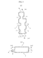
FIG. 3 is a diagram showing a cross-sectional configuration example (a) along line 3X1-3X1' and a cross-sectional configuration example (b) along line 3X2-3X2' of the shock absorber 10 shown inFIG. 2 . -
FIG 4 is a diagram showing a configuration example, on the side of afirst sidewall 4, of the shock absorber 10 shown inFIG. 2 . -
FIG. 5 is a diagram showing a configuration example, on the side of asecond sidewall 5, of the shock absorber 10 shown inFIG. 2 . -
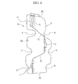
FIG. 6 is a diagram showing a configuration example, on side A (side of arear wall 3A), of the shock absorber 10 shown inFIG. 2 . -
FIG. 7 is a diagram showing a configuration example, on side B (side of anupper wall 3B) of the shock absorber 10 shown inFIG. 2 . -
FIG. 8 is a diagram showing a configuration example, on side C (side of alower wall 3C), of the shock absorber 10 shown inFIG. 2 . -
FIG. 9 is a diagram showing a configuration example, on side D (side of afront wall 3D), of the shock absorber 10 shown inFIG. 2 . -
FIG. 10 is a magnified configuration example of a third attachingpawl 13 of the shock absorber 10. -
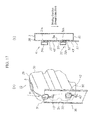
FIG. 11 is a first diagram showing a state in which theshock absorber 10 is attached onto the attachingobject 20 and is a diagram showing a state viewed from the side of the attachingobject 20. -
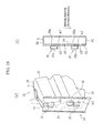
FIG. 12 is a second diagram showing a state in which theshock absorber 10 is attached onto the attachingobject 20 and is a diagram showing a state viewed from the side of thelower wall 3C. -
FIG. 13 is a third diagram showing a state in which theshock absorber 10 is attached onto the attachingobject 20 and is a diagram showing a state viewed from the side of thefirst sidewall 4. -
FIG. 14 is a fourth diagram showing a state in which theshock absorber 10 is attached onto the attachingobject 20 and is a diagram showing a state viewed from the side of thefront wall 3D. -
FIG. 15 is a first diagram showing another configuration example of the shock absorber 10 of the first embodying mode and a diagram showing a state in whichprojections holes -
FIG. 16 is a diagram showing a state in which afixing section 33 shown inFIG. 15 is inserted in the attachinghole 42 for the fixing thereof. -
FIG. 17 is a second diagram showing another configuration example of the shock absorber 10 of the first embodying mode and a diagram showing a state in which theprojections holes -
FIG. 18 is a diagram showing a state in which a fixing section 33' shown inFIG. 17 is inserted in an attaching hole 43' for the fixing thereof. -
FIG. 19 is a diagram showing an overall configuration example of a shock absorber 10 in a second embodying mode and an attachingobject 20 onto which theshock absorber 10 is attached. -
FIG. 20 is a diagram showing a cross-sectional configuration example alongline 20X-20X' of the shock absorber 10 shown inFIG. 19 . -
FIG. 21 is a diagram showing a cross-sectional configuration example alongline 21X-21X' of the shock absorber 10 shown inFIG. 19 . -
FIG. 22 is a diagram showing a cross-sectional configuration example alongline 22X-22X' of the shock absorber 10 shown inFIG. 19 . -
FIG. 23 is a diagram showing a configuration example, on the side of thefirst sidewall 4, of the shock absorber 10 shown inFIG. 19 . -
FIG. 24 is a diagram showing a configuration example, on the side of thesecond sidewall 5, of the shock absorber 10 shown inFIG. 19 . -
FIG. 25 is a diagram showing a configuration example, on side A (side of therear wall 3A), of the shock absorber 10 shown inFIG 19 . -
FIG. 26 is a diagram showing a configuration example, on side B (side of theupper wall 3B), of the shock absorber 10 shown inFIG. 19 . -
FIG. 27 is a diagram showing a configuration example, on side C (side of thelower wall 3C), of the shock absorber 10 shown inFIG. 19 . -
FIG. 28 is a diagram showing a configuration example, on side D (side of thefront wall 3D), of the shock absorber 10 shown inFIG. 19 . -
FIG. 29 is a diagram showing a state in which anaxial section 11 andremoval preventing sections body 3 are inserted in anaxial hole 21 and attachingholes object 20. -
FIG 30 is a diagram showing a state in which thebody 3 is rotated about theaxial section 11 as the axis of rotation to place portions of restricting sections 12b and 13b disposed at tip ends of theremoval preventing sections object 20. -
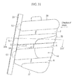
FIG. 31 is a diagram showing a configuration example, on the side of thefirst sidewall 4, of theshock absorber 10 attached onto the attachingobject 20. -
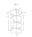
FIG. 32 is a diagram showing a configuration example, on the side of thefront wall 3D, of theshock absorber 10 attached onto the attachingobject 20. -
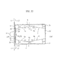
FIG. 33 is a diagram showing a cross-sectional configuration example alongline 33X-33X' shown inFIG. 31 . -
FIG. 34 is a diagram showing a configuration example of therear wall 3A. -
FIG. 35 is a diagram showing a configuration example of asplit mold 200 to form therear wall 3 A. -
FIG. 36 is a diagram showing an inflection configuration example of groove-shapedribs -
FIG. 37 is a diagram showing another configuration example of thefront wall 3D. -
FIG. 38 is a first diagram showing a configuration example in which fixingsections -
FIG. 39 is a second diagram showing a configuration example in which fixingsections -
FIG. 40 is a perspective view of theshock absorber 10 viewed from the side of therear wall 3A. -
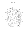
FIG. 41 is a perspective view of theshock absorber 10 viewed from the side of thefront wall 3D. -
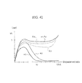
FIG. 42 is a diagram showing measurement results of shock absorbing performance. -
FIG. 43 is a diagram showing a configuration example of a shock absorber employed in measurements and tests of shock absorbing performance. -
FIG. 44 is a diagram showing an overall configuration example of ashock absorber 10 in a third embodying mode and an attachingobject 20 onto which theshock absorber 10 is attached. -
FIG. 45 is a diagram showing a cross-sectional configuration example alongline 45X-45X' of theshock absorber 10 shown inFIG. 44 . -
FIG 46 is a diagram showing a cross-sectional configuration example alongline 46X-46X' of theshock absorber 10 shown inFIG. 44 . -
FIG. 47 is a diagram showing a configuration example, on the side of anupper surface 3B, of theshock absorber 10 shown inFIG. 44 . -
FIG. 48 is a diagram showing a configuration example, on the side of alower surface 3C, of theshock absorber 10 shown inFIG. 44 . -
FIG 49 is a diagram showing a configuration example, on side A (side of arear surface 3A), of theshock absorber 10 shown inFIG. 44 . -
FIG. 50 is a diagram showing a configuration example, on side D (side of ashock receiving surface 3D), of theshock absorber 10 shown inFIG. 44 . -
FIG. 51 is a diagram showing a state of theshock absorber 10 attached onto the attachingobject 20, viewed from the side of theshock receiving surface 3D. -
FIG. 52 is a diagram showing a cross-sectional configuration example alongline 52X-52X' shown inFIG. 51 . - First, by referring to
FIG. 2 , description will be given of an outline of theshock absorber 10 of the present embodying mode.FIG. 2 shows an overall configuration example of theshock absorber 10 of the present embodying mode. - The
shock absorber 10 of the present embodying mode is characterized by including afront wall 3D to receive shock, arear wall 3A opposing thefront wall 3D, and peripheral walls (corresponding to anupper wall 3B, afirst sidewall 4, alower wall 3C, and a second sidewall 5) which connect the peripheries of thefront wall 3D and therear wall 3A to each other, and at least one attaching section (corresponding to attachingpawls 11 to 13) to attach onto the attachingobject 20 is formed to be integral with therear wall 3A, and shock received by thefront wall 3D is propagated via therear wall 3A to the attachingobject 20. - The
shock absorber 10 of the present embodying mode can be, since the attachingsections 11 to 13 are formed to be integral with therear wall 3A, easily attached and the installation space can be reduced. Next, by referring to the accompanying drawings, description will be given in detail of theshock absorber 10 of the present embodying mode. - First, by referring to
FIG. 1 , description will be given of an attaching example of theshock absorber 10 of the present embodying mode.FIG. 1 shows a state in which theshock absorber 10 shown inFIGS. 2 to 10 is installed as a shock absorber of a knee bolster 106 in acar 100. - The
car 100 shown inFIG. 1 includes acompartment 103 having afront seat 102 for a car user including adriver 101, and ameter 104 is placed on a side surface of asteering wheel 105. Thesteering wheel 105 is coupled with a steering column, not shown, and a steering support member to support the steering column is supported by an inner wall surface of the car body to be installed in a car-width direction. Theshock absorber 10 of the present embodying mode (reference is to be made toFIGS. 2 to 10 ) is attached on both sides of the steering column as a knee bolster 106 on the driver's seat side to interpose the steering column therebetween. However, each space on both sides of the steering column is elongated in association with the installing spaces of other car constituting members (ameter 104, a navigator, an air-conditioner, etc.); hence, in the elongated space, the knee bolster 106 is installed to be adjacent to eachknee 107 of thedriver 101. As a result, when thecar 100 receives shock, theknees 107 of thedriver 101 make contact with the respective knee bolsters 106 and the knee bolsters 106 absorb the shock to reduce the shock applied onto theknees 107. Incidentally,FIG 1 shows the knee bolsters 106 on the driver's seat side; however, also on the assistant driver's seat side as on the driver's seat side, the knee bolsters are installed to be adjacent to the knees of the car user sitting on the assistant driver's seat. - Next, referring to
FIGS. 2 to 10 , description will be given of a configuration example of theshock absorber 10 of the present embodying mode.FIG. 2 is a diagram showing an overall configuration example of theshock absorber 10 of the present embodying mode and the attachingobject 20 onto which theshock absorber 10 is attached,FIG. 3 (a) shows a cross-sectional configuration example along line 3X1-3X1' of theshock absorber 10 shown inFIG. 2 , andFIG. 3(b) shows a cross-sectional configuration example along line 3X2-3X2' of theshock absorber 10 shown inFIG. 2 .FIG. 4 shows a configuration example of theshock absorber 10 shown inFIG. 2 on the side of thefirst sidewall 4 andFIG. 5 shows a configuration example of theshock absorber 10 shown inFIG. 2 on the side of thesecond sidewall 5.FIG. 6 shows a configuration example of theshock absorber 10 shown inFIG. 2 on side A (side of therear wall 3A) andFIG. 7 shows a configuration example of theshock absorber 10 shown inFIG. 2 on side B (side of theupper wall 3B).FIG. 8 shows a configuration example of theshock absorber 10 shown inFIG. 2 on side C (side of thelower wall 3C) andFIG. 9 shows a configuration example of theshock absorber 10 shown inFIG. 2 on side D (side of thefront wall 3D).FIG. 10 shows a magnified configuration example of the third attachingpawl 13 of theshock absorber 10. Incidentally, in conjunction with the present embodying mode, description will be given of a situation in which a sheet of metal is employed as the attachingobject 20. However, the attachingobject 20 is not limited to the sheet of metal, but any member may be applicable. - The
shock absorber 10 of the present embodying mode is molded in a hollow shape by conducting blow molding on thermoplastic resin and includes, as shown inFIG. 3 (a) , a plurality of groove-shapedribs first sidewall 4 and thesecond sidewall 5 opposing to each other of thebody 3 including ahollow section 2. The groove-shapedribs first sidewall 4 and thesecond sidewall 5 extend, as shown inFIG. 2 , from thefront wall 3D to therear wall 3A, and the extending direction is favorably equal to the direction of shock. This makes it possible to increase rigidity against shock from the shock direction. - The
body 3 of theshock absorber 10 of the present embodying mode includes six walls which are theupper wall 3B, therear wall 3A, thelower wall 3C, thefront wall 3D, thefirst sidewall 4, and thesecond sidewall 5; and theupper wall 3B, thefirst sidewall 4, thelower wall 3C, and thesecond sidewall 5 configure a peripheral wall of thebody 3. Theshock absorber 10 of the present embodying mode is configured, as shown inFIG. 2 , such that the gap between theupper wall 3B and thelower wall 3C has a longer shape than the gap between thefirst sidewall 4 and thesecond sidewall 5. - In the
shock absorber 10 of the present embodying mode, thefront wall 3D shown inFIG. 9 receives shock and then the shock received by thefront wall 3D is propagated, via therear wall 3A which opposes thefront wall 3D and which is shown inFIG. 6 , to the attachingobject 20. In theshock absorber 10 of the present embodying mode, the parting line PL extends along theupper wall 3B, thefront wall 3D, thelower wall 3C, and therear wall 3A, to enhance rigidity of theshock absorber 10. This makes it possible that when thefront wall 3D receives shock, theshock absorber 10 is not easily cracked. - Incidentally, when the
shock absorber 10 of the present embodying mode is employed as the knee bolster 106 described above, the contour of theshock absorber 10 becomes small; hence, the position of the load point (hit point) to receive shock is easily moved in the perpendicular direction or in the horizontal direction relative to the ideal position, and the incoming angle of shock at which the shock advances toward thefront wall 3D is easily shifted in the perpendicular direction or in the horizontal direction relative to the ideal incoming angle. Incidentally, the movement described above takes place more remarkably in the perpendicular direction than in the horizontal direction. In theshock absorber 10 of the present embodying mode, the parting line PL extends along theupper wall 3B, thefront wall 3D, thelower wall 3C, and therear wall 3A; hence, it is possible that even thefront wall 3D receives shock in a state wherein such movement takes place, theshock absorber 10 does not easily crack. - Also, for the
front wall 3D, the parting line PL extends, as shown inFIG. 9 , along the upper edge (side of theupper wall 3B) and the lower edge (side of thelower wall 3C), to increase rigidity of thefront wall 3D. This makes it possible that when thefront wall 3D receives shock, thefront wall 3D does not easily crack. Further, in thefront wall 3D, the groove-shapedribs ribs ribs ribs rib 6 disposed in thefirst sidewall 4 to the parting line PL to the distance (a2,b2,c2) from the bottom section of the groove-shapedrib 7 disposed in thesecond sidewall 5 to the parting line PL, it is possible to uniformalize the rib-shapedribs front wall 3D is moved relative to the ideal position or even when the incoming angle of shock at which the shock advances toward thefront wall 3D is shifted relative to the ideal incoming angle, a desired load can be stably retained; hence, it is possible to secure a desired quantity of shock absorption. Incidentally, the contour of the parting line PL is not particularly restricted only if the parting line PL meets the conditions above and extends along the upper edge and the lower edge, and it is possible to configure it in any contour such as the contour of a straight line, the contour of a curved line, and the like. - Further, in the
first sidewall 4 and thesecond sidewall 5 which are peripheral walls to link the peripheries of thefront wall 3D and therear wall 3A to each other, there are formed, as shown inFIGS. 4 and5 , the groove-shapedribs front wall 3D to therear wall 3A. The groove-shapedribs first sidewall 4 and thesecond sidewall 5 such that the extending direction α of the groove-shapedribs rear wall 3A form the predetermined angle θ therebetween. Incidentally, the predetermined angle θ is an angle for which the extending direction α of the groove-shapedribs rear wall 3A is attached onto the attachingobject 20. This makes it possible that when thefront wall 3D receives shock, rigidity thereof against the shock is increased and the groove-shapedribs - Incidentally, in the present embodying mode, as shown in
FIGS. 4 and5 , the slender groove-shapedribs ribs ribs rib 6 formed on thefirst sidewall 4 side is equal in the contour to the groove-shapedrib 7 formed on thesecond sidewall 5 side. This makes it possible that the shock is uniformly absorbed by both groove-shapedribs ribs ribs ribs ribs ribs ribs ribs second sidewalls second sidewalls - As thermoplastic resin to constitute the
shock absorber 10 of the present embodying mode, known resin is applicable. The resin may include resin having high mechanical strength such as rigidity, the resin being, for example, polyolefin-based resin including polyethylene and polypropylene; styrene-based resin including polystyrene and ABS resin; polyester-based resin including polyethylene terephthalate, polyamide, and a mixture of these resins. - Also, in the range not to deteriorate mechanical strength (anti-shock property), there may be included one kind or two or more kinds of additives utilized in the relevant field, for example, fillers including silica; pigments, dyes, thermal stabilizers, optical stabilizers, plasticizers, antistatic agents, fire retardants, flame retardants, antiaging agents, ultraviolet-ray absorbers, antioxidants, antifogging agents, and slip additives.
- Further, the
shock absorber 10 of the present embodying mode includes, as shown inFIG. 2 , attachingpawls 11 to 13 on therear wall 3A side of thebody 3, and by engaging the attachingpawls 11 to 13 withholes 21 to 23 disposed in the attachingobject 20, it is possible to install theshock absorber 10 in a car, on therear wall 3A of thebody 3. However, to install theshock absorber 10 of the present embodying mode in a car, it is required that the attachingobject 20 is beforehand mounted on a part of the car. As a result, theshock absorber 10 of the present embodying mode can be easily installed in the car without using attaching tools such as vis and screws. - The
shock absorber 10 of the present embodying mode includes the first attachingpawl 11 formed in a hollow shape by blow molding and the second and third attachingpawls - The first attaching
pawl 11 is formed, as shown inFIG. 3 (b) , in a hollow shape to enhance rigidity. Incidentally, thehollow section 8 formed in the first attachingpawl 11 is integral with thehollow section 2 formed in thebody 3 and air is able to flow between thehollow section 2 of thebody 3 and thehollow section 8 of the first attachingpawl 11 in the configuration. - Also, since the first attaching
pawl 11 of the present embodying mode is the start point to attach theshock absorber 10 onto the attachingobject 20, the tip end of the first attachingpawl 11 is tapered. Additionally, the first attachingpawl 11 is configured in a shape such that when the first attachingpawl 11 is inserted in thehole 21 corresponding thereto, the first attachingpawl 11 is caught by the edge of thehole 21. As a result, it is possible that only the first attachingpawl 11 is easily inserted in thehole 21 to set a state in which theshock absorber 10 is caught by the attachingobject 20. - In the present embodying mode, as shown in
FIG. 2 , in the contacting section between thebody 3 and the first attachingpawl 11, there is formed a concave-shaped notch section 11' depressed toward the inside of the first attachingpawl 11 such that the first attachingpawl 11 is caught by the edge of thehole 21 by use of the notch section 11'. Further, the shape of the notch section 11' is not particularly limited, but any shape is applicable only if it is possible that the first attachingpawl 11 is caught by the edge of thehole 21. In addition, a thin section (burr) is formed in the notch section 11', and when the first attachingpawl 11 is caught by the edge of thehole 21, the thin section elastically deforms along the edge of thehole 21 such that the notch section 11' tightly makes contact with the edge of thehole 21. This makes it possible that the notch section 11' is tightly brought into contact with the edge of thehole 21 and the first attachingpawl 11 is caught by the edge of thehole 21. Also, when theshock absorber 10 of the present embodying mode is formed by blow molding, the thin section is formed between the first attachingpawl 11 and thebody 3; however, when the first attachingpawl 11 is caught by the edge of thehole 21, the thin section elastically deforms along the edge of thehole 21; hence, it is not required to cut off the thin section. - The second and third attaching
pawls FIG. 10 , a step is disposed in the attachingpawl 13, to form a centralplanar section 14 constituting the central section of the attachingpawl 13 and both-endplanar sections pawl 13 such that the both-endplanar sections pawl 13 inflect toward the side of the centralplanar section 14. - Also, coupling sections 14' and 14' in which the central
planar section 14 is coupled with the both-endplanar sections planar sections pawl 13 in thehole 23. In addition, even when the shape of the attachingpawl 13 is larger than the shape of thehole 23 corresponding to the attachingpawl 13, the both-endplanar sections pawl 13 in thehole 23. Further, after the attachingpawl 13 is engaged with thehole 23, the both-endplanar sections pawl 13 is engaged with thehole 23. Incidentally, the coupling sections 14' and 14' are favorably formed with thickness raging from 0.01 mm to 0.5 mm. As a result, the both-endplanar sections planar sections planar section 14 is favorably longer than that of the both-endplanar sections planar sections planar section 14 as the central axis. - Further, in the contacting section between the
body 3 and the attachingpawl 13, there is formed a concave-shapednotch section 17 such that when the attachingpawl 13 is inserted in thehole 23, the edge of thehole 23 engages with thenotch 17. Incidentally, the shape of thenotch section 17 is not particularly limited, but any shape is applicable only if it is possible to engage with the edge of thehole 23. Also, the centralplanar section 14 forms, due to the coupling sections 14' and 14' standing at both ends of the centralplanar section 14 to couple them with each other, a concave shape depressed toward the side of thesecond sidewall 5 relative to the both-endplanar sections planar section 14 is, the more the resin of the portion to form the coupling sections 14' and 14' is extended; hence, it is possible to make the coupling sections 14' and 14' thin. Incidentally, it is favorable that the coupling sections 14' and 14' are inclined by a predetermined angle in the configuration such that the concave shape of the centralplanar section 14 is a trapezoidal shape. This makes it easy that the both-endplanar sections planar section 14. - Further, the attaching
pawl 13 of the present embodying mode prevents the contacting position at which the centralplanar section 14 makes contact with thebody 3 and the contacting position at which the both-endplanar sections pawl 13 and thebody 3. Additionally, the attachingpawl 13 of the present embodying mode is configured such that the tip-end side of the centralplanar section 14 is inclined upward and the tip-end sides of the both-endplanar sections planar section 14 and the tip-end sections of the both-endplanar sections pawl 13 has an acute shape. This makes it possible that the tip-end side of the attachingpawl 13 is elastically deformed so that the attachingpawl 13 is easily engaged with thehole 23. Also, when the attachingpawl 13 is engaged with thehole 23, it makes contact with thehole 23 in the vicinity of the contacting section having increased strength between the attachingpawl 13 and thebody 3; hence, after the attachingpawl 13 is engaged with thehole 23, it is possible to fixedly attach theshock absorber 10 onto the attachingobject 20. - Incidentally, while
FIG. 10 shows a magnified configuration example of the third attachingpawl 13, the second attachingpawl 12 is also configured in the same way as for the third attachingpawl 13. However, while the centralplanar section 14 of the third attachingpawl 13 has a concave shape depressed toward thesecond sidewall 5 side, the centralplanar section 14 of the second attachingpawl 12 has a concave shape depressed toward thefirst sidewall 4 side. Hence, the concave -shaped section of the centralplanar section 14 of the third attachingpawl 13 and the concave-shaped section of the centralplanar section 14 of the second attachingpawl 12 face each other toward the center of thebody 3. - In the installation of the
shock absorber 10 of the present embodying mode in a car, first, by using the first attachingpawl 11 having rigidity as the start point, only the first attachingpawl 11 is inserted in thehole 21 associated with the first attachingpawl 11 in a state in which the first attachingpawl 11 is caught by thehole 21 by use of the notch section 11' of the first attachingpawl 11. Next, the second and third attachingpawls holes pawls pawls holes FIGS. 11 to 14 , to install theshock absorber 10 in the car. Incidentally,FIGS. 11 to 14 show states in which the attachingpawls 11 to 13 of theshock absorber 10 are engaged with theholes 21 to 23 disposed in the attachingobject 20, whereinFIG. 11 shows a state viewed from the side of the attachingobject 20 in which the attachingpawls 11 to 13 are engaged with theholes 21 to 23,FIG. 12 shows a state viewed from the side of thelower wall 3C,FIG. 13 shows a state viewed from the side of thefirst sidewall 4, andFIG. 14 shows a state viewed from the side of thefront wall 3D. - In the
shock absorber 10 of the present embodying mode, as shown inFIG. 13 , the groove-shapedrib 6 extending from thefront wall 3D to therear wall 3A is formed in thefirst sidewall 4, and the extending direction α of the groove-shapedrib 6 and the vertical direction β vertical to therear wall 3A form the predetermined angle θ therebetween. Hence, the groove-shapedrib 6 extends in a direction inclined with respect to the vertical direction β vertical to therear wall 3A. This makes it possible, as shown inFIG. 13 , that when therear wall 3A is attached onto the attachingobject 20, the extending direction α of the groove-shapedrib 6 is equal to the direction of shock. As a result, it is possible that at reception of shock by thefront wall 3D, rigidity against the shock is enhanced and the shock is efficiently absorbed by the groove-shapedrib 6. Incidentally, whileFIG. 13 shows the extending direction α of the groove-shapedrib 6 on thefirst sidewall 4 side, the extending direction α of the groove-shapedrib 7 on thesecond sidewall 5 side is also the same as for the groove-shapedrib 6 on thefirst sidewall 4 side.FIG. 13 shows a state viewed from a direction vertical to thefirst sidewall 4, and the extending direction α of the groove-shapedrib 6 is inclined with respect to the vertical direction β vertical to therear wall 3A. - Incidentally, to install the
shock absorber 10 of the present embodying mode in a car, it is required that the attachingobject 20 is beforehand mounted on a part of the car. As a result, theshock absorber 10 of the present embodying mode can be easily installed in the car without using attaching tools such as vis and screws. As a result, the attaching operation can be facilitated. Further, since the second and third attachingpawls pawl 11 is inserted in thehole 21 that the second and third attachingpawls holes - Incidentally, in the
shock absorber 10 of the present embodying mode, there are disposed, as shown inFIG. 2 , the attachingpawls 12 to 13 on the inflected parting line PL to prevent the attachingpawls 12 to 13 from taking positions on a straight line. This makes it possible, as shown inFIG. 11 , to prevent the positions at which theshock absorber 10 is attached onto the attachingobject 20 from being on a straight line. As a result, it is possible to stably fix theshock absorber 10 onto the attachingobject 20. Also, in the first attachingpawl 11, there exists the notch section 11'; further, in the second and third attachingpawl notch sections 17; hence, it is possible that by use of thenotch sections 11' and 17, the attachingpawls 11 to 13 engage with edges of theholes 21 to 23, to fixedly attach theshock absorber 10 onto the attachingobject 20. - As above, the
shock absorber 10 of the present embodying mode is characterized, as shown inFIG. 2 , by including afront wall 3D to receive shock, arear wall 3A opposing thefront wall 3D, and peripheral walls (anupper wall 3B, afirst sidewall 4, alower wall 3C, and a second sidewall 5) which connect the peripheries of thefront wall 3D and therear wall 3A to each other, and at least one attaching section (attachingpawls 11 to 13) to attach onto the attachingobject 20 is formed to be integral with therear wall 3A, and shock received by thefront wall 3D is propagated via therear wall 3A to the attachingobject 20. - The
shock absorber 10 of the present embodying mode can be, since the attachingsections 11 to 13 are formed to be integral with therear wall 3A, easily attached and the installation space can be reduced. - Further, the
shock absorber 10 of the present embodying mode includes a hollow, first attachingpawl 11 and solid, second and third attachingpawls pawl 11 as the start point, the attachingpawls 11 to 13 are engaged with theholes 21 to 23 disposed in the attachingobject 20, to attach theshock absorber 10 onto the attachingobject 20. This makes it possible that theshock absorber 10 is attached onto the attachingobject 20 without using attaching tools such as vis and screws; hence, the attaching operation of theshock absorber 10 can be facilitated. - Also, for the second and third attaching
pawls planar section 14 is coupled with the both-endplanar sections planar sections planar section 14. This makes it possible to intentionally inflect the second and third attachingpawls planar section 14; hence, it is possible to easily insert the second and third attachingpawls holes object 20, and after the insertion, the second and third attachingpawls holes - Incidentally, in the present embodying mode described above, the attaching
pawls 11 to 13 of theshock absorber 10 are engaged with theholes 21 to 23 disposed in the attachingobject 20. However, it is also possible that by beforehand forming theholes 21 to 23 corresponding to the attachingpawls 11 to 13 of theshock absorber 10 on a part of a car, the attachingpawls 11 to 13 of theshock absorber 10 are directly attached onto a part (attaching object) of the car. - Also, in the present embodying mode described above, as shown in
FIG. 2 , the configuration includes the hollow, first attachingpawl 11 and the solid, second and third attachingpawls pawl 11 as the start point, the attachingpawls 11 to 13 are engaged with theholes 21 to 23 disposed in the attachingobject 20, to attach theshock absorber 10 onto the attachingobject 20. - However, it is also possible that the hollow, first attaching
pawl 11 is replaced by a solid attaching pawl to include only solid attaching pawls such that the solid attaching pawls are engaged with the holes disposed in the attachingobject 20, to attach theshock absorber 10 onto the attachingobject 20. - In addition, it is also possible that the solid, second and third attaching
pawls pawl 11 to include only hollow attaching pawls such that the hollow attaching pawls are engaged with the holes disposed in the attachingobject 20, to attach theshock absorber 10 onto the attachingobject 20. - Even in such configuration, since the
shock absorber 10 can be attached onto the attachingobject 20 without using attaching tools such as vis and screws, the attaching operation of theshock absorber 10 can be facilitated. That is, in a construction in which the attaching pawls are formed to be integral with therear wall 3A and therear wall 3A can be attached onto the attachingobject 20 by use of the attaching pawls, any attaching construction is applicable. Incidentally, the attaching pawls are favorably disposed on the parting line PL. This makes it possible that therear wall 3A does not easily crack when shock is received by thefront wall 3D. - Also, in the present embodying mode described above, as shown in
FIG. 2 , therear wall 3A is attached onto the attachingobject 20 by use of the attachingpawls 11 to 13 formed to be integral with therear wall 3A. However, it is also possible, as shown inFIGS. 15 and16 , to attach therear wall 3A onto the attachingobject 20 by use ofprojections section 33 which are formed to be integral with therear wall 3A. Also in this case, as for theshock absorber 10 of the present embodying mode described above, theshock absorber 10 can be attached onto the attachingobject 20 without using attaching tools such as vis and screws. - When installing the
shock absorber 10 shown inFIGS. 15 and16 in a car, first, as shown inFIG. 15 , tip ends 31b and 32b constituting theprojections holes axial sections projections projections holes FIG. 16 , to engage the fixingsection 33 with the attachinghole 42 and to fix the fixingsection 33 on an edge section of the attachinghole 42 such that the fixingsection 33 restricts movement of theshock absorber 10 in a reverse direction with respect to the moving direction. This makes it possible to install theshock absorber 10 in the car. Theprojections section 33 of this embodying mode are formed to be integral with therear wall 3A. Further, theprojections section 33 include hollow sections integral with the hollow section of thebody 3 so that air flows between the hollow section of thebody 3 and the hollow sections of theprojections section 33 in the configuration. The fixingsection 33 includes a firstinclined section 34 and a secondinclined section 35 such that the fixingsection 33 conducts a parallel movement while an inclined surface of the firstinclined section 34 makes contact with the attachingobject 20, and when the fixingsection 33 is engaged with the attachinghole 42, an inclined surface of the secondinclined section 35 makes contact with the edge section of the attachinghole 42, and the fixingsection 33 is fixed on the edge section of the attachinghole 42. - As above, the
shock absorber 10 of the present embodying mode shown inFIGS. 15 and16 includes theprojections section 33 which are projected from therear wall 3A of thebody 3, and theprojections holes object 20 and theprojections holes section 33 is inserted and is fixed in the attachinghole 42 disposed in the attachingobject 20. As a result, since theshock absorber 10 can be attached onto the attachingobject 20 without using attaching tools such as vis and screws, the attaching operation of theshock absorber 10 is facilitated. - Also, the
shock absorber 10 of the present embodying mode shown inFIGS. 15 and16 can make thebody 3 conduct a parallel movement on almost a straight line along the attachingobject 20 by using theprojections holes body 3 with respect to the attachingobject 20. Further, the fixingsection 33 is inserted and is fixed in the attachinghole 42, to thereby attach the fixingsection 33 onto the attachinghole 42; hence, it is possible to visually recognize the state whether or not theshock absorber 10 is attached onto the attachingobject 20, and occurrence of attachment failure can be prevented. - In addition, the shape of the
shock absorber 10 of the embodying mode shown inFIGS. 15 and16 is a shape elongated in the moving direction described above; hence, when compared with a case in which theshock absorber 10 is rotated to be attached onto the attachingobject 20, it is possible to reduce the attaching space of theshock absorber 10. For example, in the case in which theshock absorber 10 is rotated to be attached onto the attachingobject 20, the attaching space is required for the area of the rotation radius of theshock absorber 10, and it is not possible to arrange any other members in the attaching space. In contrast thereto, theshock absorber 10 of the embodying mode shown inFIGS. 15 and16 conducts a parallel movement in a linear manner along the attachingobject 20 to be attached onto the attachingobject 20; hence, even when other members exist in the periphery of the attachinghole 42 of the attachingobject 20, theshock absorber 10 can be attached. - Incidentally, in the
shock absorber 10 of the embodying mode shown inFIGS. 15 and16 , the hole in which the fixingsection 33 is inserted to be fixed and the hole in which theprojection 32 is inserted are integrally formed. However, it is also possible that an exclusive hole (fixing hole) is disposed to fix the fixingsection 33 such that the fixingsection 33 is inserted and is fixed in the fixing hole. - Further, it is also possible that the
shock absorber 10 shown inFIGS. 15 and16 includes fixing sections 33' in the tip ends 31b and 32b of theprojections FIGS. 17 and18 such that the fixing sections 33' are inserted in fixing holes 43' disposed in the attachingobject 20, to thereby fix the fixing sections 33' in the fixing holes 43'. - The
shock absorber 10 shown inFIGS. 17 and18 is configured in the same way as for theshock absorber 10 shown inFIGS. 15 and16 excepting that it includes the fixing sections 33' in the tip ends 31b and 32b of theprojections FIG. 17 , the tip ends 31b and 32b constituting theprojections holes axial sections projections projections holes FIG. 18 , and the fixing section 33' is engaged with the fixing hole 43', to fix the fixing section 33' in the fixing hole 43'. This makes it possible to attach theshock absorber 10 onto the attachingobject 20. Incidentally, the shape of the fixing section 33' is favorably a shape to easily get over the attachingobject 20. Also, it is favorably a shape such that when thebody 3 is moved, the tip ends 31b and 32b of theprojections object 2 and is easily inserted in the fixing hole 43'. It is hence possible that the attachingobject 20 is interposed between part of the bottom surface of thetip end 31b (32b) of theprojection body 3 such that theprojections holes projections projections object 20 to fix the fixing sections 33'. - Incidentally, in the
shock absorber 10 shown inFIGS. 15 to 18 as in the embodying mode described above, the parting line PL extends along theupper wall 3B, thefront wall 3D, thelower wall 3C, and therear wall 3A, and theprojections sections 33 and 33' are formed on the parting line PL. Hence, on the parting line PL at the positions of theprojections sections 33 and 33', there remain burrs. In a situation in which burrs remain at the positions of theprojections sections 33 and 33'; as shown inFIGS. 15 to 18 , when theprojections holes section 33 in the attachinghole 42 and to fix the fixing section 33' in the fixing hole 43', theprojections sections 33 and 33' cannot be brought into contact with edges of the attachingholes projections sections 33 and 33'; hence, gaps take place between theprojections sections 33 and 33' and the edges of the attachingholes shock absorber 10 onto the attachingobject 20 is moved, which leads to a fear of reduction in the attaching precision of theshock absorber 10. Incidentally, even when it is desired to remove the burrs, it is difficult to clearly remove all burrs; hence, some burrs remain at theprojections sections 33 and 33' and the situation of the problem above takes place. - Hence, it is desirable that in the attaching
object 20 onto which theshock absorber 10 shown inFIGS. 15 to 18 is attached, notch sections are formed on edges of the attachingholes projections sections 33 and 33', and as shown inFIGS. 15 to 18 , when theprojections holes section 33 in the attachinghole 42 and to fix the fixing section 33' in the fixing hole 43', the parting line PL at theprojections sections 33 and 33' is placed at the notch sections, not shown, formed in the edges of the attachingholes FIGS. 15 to 18 , when theprojections holes section 33 in the attachinghole 42 and to fix the fixing section 33' in the fixing hole 43', it is possible that the burrs remaining on the parting line PL at the positions of theprojections sections 33 and 33' are accommodated in the notch sections, to thereby bring theprojections sections 33 and 33' into contact with the edges of the attachingholes projections sections 33 and 33' do not become hindrances, and theprojections sections 33 and 33' can be moved to positions to make contact with the edges of the attachingholes shock absorber 10. Incidentally, the shape of the notch sections is not particularly limited, but any shape may be used in the configuration only if the shape can accommodate the burrs remaining at theprojections sections 33 and 33'. - Incidentally, in the
shock absorber 10 shown inFIGS. 15 to 18 , theprojections shock absorber 10 are inserted in the attachingholes object 20 to fix the fixingsections 33 and 33' of theshock absorber 10 in the attachinghole 42 and the fixing hole 43' disposed in the attachingobject 20. However, it is also possible that by beforehand forming the attachingholes projections sections 33 and 33' of theshock absorber 10 on a part of a car, theprojections sections 33 and 33' of theshock absorber 10 are directly attached onto a part (attaching object) of the car. - Further, in the
shock absorber 10 shown inFIGS. 17 and18 , the fixing section 33' of theshock absorber 10 is inserted in the fixing hole 43', to fix the fixing section 33'. However, the structure of the fixing section 33' and the fixing hole 43' is not particularly limited only if the fixing section 33'can be fixed, and a fixing section of any structure may be disposed on theshock absorber 10 and the attachingobject 20. - Next, description will be given of a second embodying mode example.
- First, by referring to
FIGS. 19 ,29 , and30 , description will be given of ashock absorber 10 in a second embodying mode.FIG. 19 shows an overall configuration example of ashock absorber 10 of the present embodying mode and an attachingobject 20 onto which theshock absorber 10 is attached;FIG. 29 shows a state in which anaxial section 51 andremoval preventing sections body 3 are inserted in anaxial hole 61 and attachingholes object 20, andFIG. 30 shows a state in which thebody 3 is rotated about theaxial section 51 as a rotary axis to place portions of restrictingsections removal preventing sections object 20. - The
shock absorber 10 of the present embodying mode has an aspect to include, as shown inFIG. 19 , abody 3, anaxial section 51 projecting from thebody 3, andremoval preventing sections body 3; and theremoval preventing sections removal restricting sections object 20 to restrict removal of theaxial section 51 from theaxial hole 61 when theaxial section 51 is inserted in anaxial hole 61 disposed in the attachingobject 20 as shown inFIG. 29 and the body is rotated as shown inFIG. 30 . Incidentally, as in the configuration example described above, when theshock absorber 10 includes theaxial section 51 and theremoval preventing sections removal preventing section - Further, the
shock absorber 10 of the present embodying mode has an aspect to include, as shown inFIG. 19 , abody 3 and a plurality ofremoval preventing sections body 3; and theremoval preventing sections FIG. 29 , restrictingsections object 20 to restrict removal of theremoval preventing sections holes removal preventing sections holes object 20 and thebody 3 is rotated, as shown inFIG. 30 , such that theremoval preventing sections holes shock absorber 10 includes a plurality ofremoval preventing sections removal preventing section - In the
shock absorber 10 of the present embodying mode, when thebody 3 is rotated, it is possible to restrict removal of theaxial section 51 from theaxial hole 61 and to restrict removal of theremoval preventing sections holes shock absorber 10 of the present embodying mode, no attaching tool is required, and the attaching operation can be facilitated. Next, referring to the accompanying drawings, description will be given in detail of theshock absorber 10 of the present embodying mode. - First, referring to
FIGS. 19 to 28 , description will be given of a configuration example of theshock absorber 10 of the present embodying mode.FIG. 19 is a diagram showing an overall configuration example of theshock absorber 10 of the present embodying mode and the attachingobject 20 onto which theshock absorber 10 is attached,FIG. 20 shows a cross-sectional configuration example alongline 20X-20X' of theshock absorber 10 shown inFIG. 19 ,FIG. 21 shows a cross-sectional configuration example alongline 21X-21X' of theshock absorber 10 shown inFIG. 19 , andFIG 22 shows a cross-sectional configuration example alongline 22X-22X' of theshock absorber 10 shown inFIG. 19 .FIG. 23 shows a configuration example of theshock absorber 10 shown inFIG. 19 on the side of thefirst sidewall 4 andFIG. 24 shows a configuration example of theshock absorber 10 shown inFIG. 19 on the side of thesecond sidewall 5.FIG. 25 shows a configuration example of theshock absorber 10 shown inFIG. 19 on side A (side of therear wall 3A) andFIG. 26 shows a configuration example of theshock absorber 10 shown inFIG. 19 on side B (side of theupper wall 3B).FIG. 27 shows a configuration example of theshock absorber 10 shown inFIG. 19 on side C (side of thelower wall 3C) andFIG. 28 shows a configuration example of theshock absorber 10 shown inFIG. 19 on side D (side of thefront wall 3D). Incidentally, in conjunction with the present embodying mode, description will be given of a situation in which a sheet of metal is employed as the attachingobject 20. However, the attachingobject 20 is not limited to the sheet of metal, but any member may be applicable. - The
shock absorber 10 of the present embodying mode is molded in a hollow shape by conducting blow molding on thermoplastic resin and includes, as shown inFIG. 20 , a plurality of groove-shapedribs first sidewall 4 and thesecond sidewall 5 opposing to each other of thebody 3 including ahollow section 2. The groove-shapedribs first sidewall 4 and thesecond sidewall 5 extend as shown inFIG. 19 from thefront wall 3D to therear wall 3A, and the extending direction thereof is favorably equal to the direction of shock. This makes it possible to increase rigidity against shock from the direction of shock. - In the
shock absorber 10 of the present embodying mode, thefront wall 3D shown inFIG. 28 receives shock and then the shock received by thefront wall 3D is propagated, via therear wall 3A, which opposes thefront wall 3D and which is shown inFIG. 25 , to the attachingobject 20. In theshock absorber 10 of the present embodying mode, the parting line PL extends along theupper wall 3B, thefront wall 3D, thelower wall 3C, and therear wall 3A, to enhance rigidity of theshock absorber 10. This makes it possible that when thefront wall 3D receives shock, theshock absorber 20 is not easily cracked. - When the
shock absorber 10 of the present embodying mode is employed as the knee bolster 106 described above, since the contour of theshock absorber 10 becomes small, the position of the load point (hit point) to receive shock is easily moved in the perpendicular direction or in the horizontal direction relative to the ideal position, and the incoming angle of shock at which the shock advances toward thefront wall 3D is easily shifted in the perpendicular direction or in the horizontal direction relative to the ideal incoming angle. Incidentally, the movement described above takes place more remarkably in the perpendicular direction than in the horizontal direction. Therefore, in theshock absorber 10 of the present embodying mode, the parting line PL extends along theupper wall 3B, thefront wall 3D, thelower wall 3C, and therear wall 3A. As a result, it is possible that even thefront wall 3D receives shock in a state wherein such movement takes place, theshock absorber 10 does not easily crack. - Also, for the
front wall 3D, the parting line PL extends, as shown inFIG. 28 , along the upper edge (side of theupper wall 3B) and the lower edge (side of thelower wall 3C), to increase rigidity of thefront wall 3D. This makes it possible that when thefront wall 3D receives shock, thefront wall 3D does not easily crack. - Further, in the
front wall 3D, the groove-shapedribs ribs ribs ribs front wall 3D, by equalizing the distance (a1,b1,c1) from the bottom section of the groove-shapedrib 6 disposed in thefirst sidewall 4 to the parting line PL to the distance (a2,b2,c2) from the bottom section of the groove-shapedrib 7 disposed in thesecond sidewall 5 to the parting line PL, it is possible to uniformalize the rib-shapedribs front wall 3D is moved relative to the ideal position or even when the incoming angle of shock at which the shock advances toward thefront wall 3D is shifted relative to the ideal incoming angle, a desired load can be stably retained and it is possible to secure a desired quantity of shock absorption. - Incidentally, the contour of the parting line PL is not particularly restricted only if the parting line PL meets the conditions above and extends along the upper edge (side of the
upper wall 3B) and the lower edge (side of thelower wall 3C), and it is possible to configure it in any contour such as the contour of a straight line, the contour of a curved line, and the like. However, in theshock absorber 10 of the present embodying mode, since shock is received on thefront wall 3D side and therear wall 3A side is attached onto the attachingobject 20, it is desired that no compression section CP remains in the parting line PL passing thefront wall 3D and therear wall 3A to form the surface thereof flat and the compression section CP remains in the parting line PL passing theupper wall 3B and thelower wall 3C. The compression section CP can be formed by welding thermoplastic resin clamped by a split mold when theshock absorber 10 is the molded. It is hence possible to prevent occurrence of crack from the parting line PL and to implement stable shock absorption. - Further, in the
first sidewall 4 and thesecond sidewall 5 which are peripheral walls to link thefront wall 3D with therear wall 3A, there are formed, as shown inFIGS. 23 and24 , the groove-shapedribs front wall 3D to therear wall 3A. The groove-shapedribs first sidewall 4 and thesecond sidewall 5 such that the extending direction α of the groove-shapedribs rear wall 3A form the predetermined angle θ therebetween. Incidentally, the predetermined angle θ is an angle for which the extending direction α of the groove-shapedribs rear wall 3A is attached onto the attachingobject 20. This makes it possible that when thefront wall 3D receives shock, rigidity thereof against the shock is increased and the groove-shapedribs - Incidentally, in the present embodying mode, as shown in
FIGS. 23 and24 , the slender groove-shapedribs ribs ribs rib 6 formed on thefirst sidewall 4 side is equal in the contour to the groove-shapedrib 7 formed on thesecond sidewall 5 side. This makes it possible that the shock is uniformly absorbed by both groove-shapedribs - Further, in the present embodying mode, the slender groove-shaped
ribs ribs ribs ribs ribs ribs ribs second sidewalls second sidewalls - As thermoplastic resin to constitute the
shock absorber 10 of the present embodying mode, known resin is applicable. The resin may include resin having high mechanical strength such as rigidity, the resin being, for example, polyolefin-based resin including polyethylene and polypropylene, styrene-based resin including polystyrene and ABS resin, polyester-based resin including polyethylene terephthalate, polyamide, and a mixture of these resins. - Also, in the range not to deteriorate mechanical strength (anti-shock property), there may be included one kind or two or more kinds of additives utilized in the relevant field, for example, fillers including silica and the like, pigments, dyes, thermal stabilizers, optical stabilizer, plasticizers, antistatic agents, fire retardants, flame retardants, antiaging agents, ultraviolet-ray absorbers, antioxidants, antifogging agents, and slip additives.
- The
shock absorber 10 of the present embodying mode includes, as shown inFIG. 19 , anaxial section 51 andremoval preventing sections rear wall 3A of thebody 3. Theaxial section 51 and theremoval preventing sections shock absorber 10 onto the attachingobject 20. Thebody 3 includes six walls which are theupper wall 3B, therear wall 3A, thelower wall 3C, thefront wall 3D, thefirst sidewall 4, and thesecond sidewall 5; and theupper wall 3B, thefirst sidewall 4, thelower wall 3C, and thesecond sidewall 5 configure a peripheral wall of thebody 3. Theshock absorber 10 of the present embodying mode is configured, as shown inFIG. 19 , such that the gap between theupper wall 3B and thelower wall 3C has a longer shape than the gap between thefirst sidewall 4 and thesecond sidewall 5. - The
axial section 51 is configured in the shape of a frustum of circular cone, and as shown inFIG. 29 , theaxial section 51 is inserted in theaxial hole 61 disposed in the attachingobject 20 in association with theaxial section 51 and thebody 3 is rotated to be moved relative to the attachingobject 20 by using theaxial section 51 as the axis of rotation as shown inFIG. 30 in the configuration. Incidentally, theaxial section 51 is not limited to the shape of a frustum of circular cone, but may be configured in an arbitrary shape such as a cylindrical shape only if the shape allows the rotation of thebody 3 by using theaxial section 51 as the axis. - Additionally, the
removal preventing sections FIG. 29 , theremoval preventing sections holes removal preventing sections object 20, and as shown inFIG. 30 , when thebody 3 is rotated relative to the attachingobject 20 by using theaxial section 51 as the axis of rotation, thebody 3 is moved such that the attachingobject 20 is interposed between part of bottom surfaces of the restrictingsections removal preventing sections body 3, and part of bottom surfaces of the restrictingsections removal preventing sections object 20, to thereby restrict the removal of theremoval preventing sections holes shock absorber 10 in a car. However, to install theshock absorber 10 of the present embodying mode in a car, it is required that the attachingobject 20 is beforehand mounted on a part of the car. As a result, theshock absorber 10 of the present embodying mode can be easily installed in the car without using attaching tools such as vis and screws. - Further, as for the
shock absorber 10 of the present embodying mode, theshock absorber 10 can be attached onto the attachingobject 20 by use of theaxial section 51 and theremoval preventing sections rear wall 3A; hence, it is possible to reduce the installation space to attach theshock absorber 10 onto the attachingobject 20. For example, as in the prior art, when the attaching section is disposed in theperipheral walls rear wall 3A, there is required an excessive space for the attaching section, and the installation space is enlarged. In contrast thereto, in theshock absorber 10 of the present embodying mode, the attaching sections (theaxial section 51, theremoval preventing sections 52, 53) are disposed in therear wall 3A and theshock absorber 10 is attached onto the attachingobject 20 by use of the attachingsections shock absorber 10 of the present embodying mode, theshock absorber 10 is attached onto the attachingobject 20 by use of theaxial section 51 and theremoval preventing sections rear wall 3A; hence, as shown inFIG. 20 , adepression 40 can be formed by depressing part of thefirst sidewall 4 as the peripheral wall toward the inside. As a result, when the area of the peripheral wall is reduced and theshock absorber 10 is installed in the installation space, it is possible to prevent interference with other car constituting members. The position and the shape to form thedepression 40 are not particularly limited and it is possible to arbitrarily form it based on the installation space and the relationship of installation for the other car constituting members. - The
axial section 51 of the present embodying mode is formed, as shown inFIG. 21 , in a hollow shape by blow molding to enhance rigidity. Incidentally, thehollow section 8 formed in theaxial section 51 is integral with thehollow section 2 formed in thebody 3 and air is able to flow between thehollow section 2 of thebody 3 and thehollow section 8 of theaxial section 51 in the configuration. - Also, the
axial hole 61 corresponding to theaxial section 51 is configured in a shape equal in size to the outer shape of theaxial section 51, to rotate theaxial section 51 in theaxial hole 61. For example, when theaxial section 51 is configured in the frustum of circular cone, theaxial hole 61 is configured in a circular shape. - Further, the
removal preventing sections FIG. 22 , in a hollow shape by blow molding, to enhance rigidity. WhileFIG. 22 shows a configuration example of oneremoval preventing section 53, the other oneremoval preventing section 52 is also configured in almost the same way as for the configuration shown inFIG. 22 . In addition, thehollow sections 9 formed in theremoval preventing sections hollow section 2 formed in thebody 3 and air is able to flow between thehollow section 2 of thebody 3 and thehollow sections 9 of theremoval preventing sections - Also, the
removal preventing sections FIG. 23 ,axial sections rear wall 3A of thebody 3 and the restrictingsections axial sections FIGS. 29 and30 , when thebody 3 is rotated to be moved by using theaxial section 51 as the axis of rotation, thebody 3 is placed on one surface of the attachingobject 20, the restrictingsections object 20, and theaxial sections holes body 3 is rotated to be moved by using theaxial section 51 as the axis of rotation, part of the restrictingsections object 20, to thereby restrict removal of theremoval preventing sections holes - Further, in the
removal preventing sections sections body 3, and when thebody 3 is rotated to be moved by using theaxial section 51 as the axis of rotation, the thin sections (burrs) 52c and 53c are deformed by the attachingobject 20 such that the restrictingsections object 20 and the rear surface of the attachingobject 20 is tightly brought into contact with thebody 3 by use of the thin sections (burrs) 52c and 53c. This makes it possible to fix the attachingobject 20 in the state in which part of the restrictingsections object 20. - Also, when the
shock absorber 10 of the present embodying mode is formed by blow molding, the thin sections (burrs) 52c and 53c are inevitably formed between the restrictingsections removal preventing sections body 3; however, when thebody 3 is rotated to be moved by using theaxial section 51 as the axis of rotation, the thin sections (burrs) 52c and 53c can be deformed by the attachingobject 20; hence, it is not required to cut off the thin sections (burrs) 52c and 53c after the blow molding, and the post-processing (the finishing process such as the removing of burrs) after the blow molding can be simplified. - In the
shock absorber 10 of the present embodying mode, theaxial section 51 and theremoval preventing sections rear wall 3A. As a result, when theshock absorber 10 receives shock, it is possible to prevent crack in the parting line PL on therear wall 3 A and the shock absorbing performance can be secured. - In addition, the rear wall 3Aof the present embodying mode includes, as shown in
FIGS. 21 and22 , aconvex section 30 projecting toward the attaching object, not shown. It is favorable that theconvex section 30 is formed on both sides (side of thefirst sidewall 4 and side of the second sidewall 5) of the parting line PL (positions at which theaxial section 51 and theremoval preventing sections rear wall 3A. Hence, when therear wall 3A is attached onto the attaching object, theconvex sections 30 formed on both sides (side of thefirst sidewall 4 and side of the second sidewall 5) of therear wall 3A, rather than the positions of the parting line PL (positions at which theaxial section 51 and theremoval preventing sections body 3; hence, theshock absorber 10 does not easily fall down and it is possible to stably fix theshock absorber 10 on the attaching object. Also, even when shock is received by thefront wall 3D, since theconvex sections 30 formed on both sides (side of thefirst sidewall 4 and side of the second sidewall 5) of therear wall 3A opposing thefront wall 3D make contact with the attaching object, it is possible to prevent the lateral fall-down and the rotation of theshock absorber 10. - Also, the
shock absorber 10 of the present embodying mode includes, as shown inFIGS. 21 and22 , athin section 31 in a corner to couple thefront wall 3D to the sidewalls (thefirst sidewall 4 and the second sidewall 5). Thickness of thethin section 31 is configured in a range from 30% to 70% of the mean thickness of the wall sections of theshock absorber 10. Thethin section 31 can be formed by adjusting the curved shape of the corner which couples thefront wall 3D with the sidewalls (thefirst sidewall 4 and the second sidewall 5). That is, by reducing the radius of curvature of the mold to form the corner, it is possible to produce the corner as a thin section. - Further, the
shock absorber 10 of the present embodying mode includes, as shown inFIG. 20 , athin section 31 in the sections of the groove-shapedribs first sidewall 4 and thesecond sidewall 5. In this case, by increasing the quantity of extension of resin in the sections to form the groove-shapedribs thin section 31. That is, when the curved shape of the mold to form the groove-shapedribs thin section 31. - The
shock absorber 10 of the present embodying mode includes, as shown inFIGS. 21 and22 , athin section 31 in a corner to couple thefront wall 3D to the sidewalls (thefirst sidewall 4 and the second sidewall 5) and, as shown inFIG. 20 , in the sections of the groove-shapedribs first sidewall 4 and the second sidewall 5); hence, when theshock absorber 10 receives shock, the positions of thethin section 31 preferentially buckle. As a result, when shock is received, theshock absorber 10 starts buckling without acting against the shock, and it is possible to efficiently absorb the shock. Also, even when the position of the load point (hit point) to receive shock by thefront wall 3D is moved relative to the ideal position or the incoming angle of shock at which the shock advances toward thefront wall 3D is shifted relative to the ideal incoming angle, thethin section 31 efficiently absorbs the shock; hence, it is possible to prevent the lateral fall-down and the rotation of theshock absorber 10. - The mean thickness of the wall sections constituting of the
shock absorber 10 of the present embodying mode is configured in a range from 0.7 mm to 5.0 mm, and thethin section 31 described above is favorably configured with thickness in the range from 30% to 70% of the mean thickness. This makes it possible to efficiently absorb the shock. - Incidentally, the mean thickness can be calculated as below. For example, in the cross-sections at three points in the upper-end side (side of the
upper wall 3B), the center, and the lower-end side (side of thelower wall 3C) of the sidewalls (thefirst sidewall 4 and the second sidewall 5) shown inFIG. 20 (however, the positions where the groove-shapedribs front wall 3D with the sidewalls (thefirst sidewall 4 and the second sidewall 5)), thickness is measured by a vernier caliper at portions (six positions in total) of intersecting points of a perpendicular bisector of a straight line connecting two mold split points, and a mean value of the resultant six measured values is calculated as the mean thickness. This makes it possible to calculate the mean thickness of the wall sections constituting theshock absorber 10. - To attach the
shock absorber 10 of the present embodying mode onto the attachingobject 20, theaxial section 51 is inserted in theaxial hole 61 and theremoval preventing sections holes FIG. 29 . Next, by using theaxial section 51 as the axis of rotation, thebody 3 is rotated to be moved by a predetermined angle (for example, 30°) relative to the attachingobject 20 as shown inFIG. 30 , to set a state in which part of the restrictingsections removal preventing sections object 20. This makes it possible to restrict the removal of theaxial section 51 and theremoval preventing sections axial hole 61 and the attachingholes shock absorber 10 can be attached onto the attachingobject 20 as shown inFIGS. 31 to 33 . Incidentally,FIGS. 31 to 33 show a state in which theshock absorber 10 is attached onto the attachingobject 20;FIG. 31 shows a state viewed from the side of thefirst sidewall 4 as the peripheral wall of theshock absorber 10,FIG. 32 shows a state viewed from the side of thefront wall 3D, andFIG. 33 is a diagram showing a cross-sectional configuration example alongline 33X-33X' shown inFIG. 31 . - In the
shock absorber 10 of the present embodying mode, as shown inFIG. 31 , the groove-shapedrib 6 extending from thefront wall 3D to therear wall 3A is formed in thefirst sidewall 4 such that the extending direction α of the groove-shapedrib 6 and the vertical direction β vertical to therear wall 3A form the predetermined angle θ therebetween. Hence, the groove-shapedrib 6 extends in a direction inclined relative to the vertical direction β vertical to therear wall 3A. Consequently, as shown inFIG 31 , when therear wall 3A is attached onto the attachingobject 20, it is possible to make the extending direction α of the groove-shapedrib 6 equal to the direction of shock. As a result, it is possible that when thefront wall 3D receives shock, rigidity thereof against the shock is increased and the groove-shapedrib 6 efficiently absorbs the shock. Incidentally, whileFIG. 31 shows the extending direction α of the groove-shapedrib 6 on the side of thefirst sidewall 4, also the extending direction α of the groove-shapedrib 7 on the side of thesecond sidewall 5 is the same as for the groove-shapedrib 6 on the side of thefirst sidewall 4.FIG. 31 shows a state viewed from a direction vertical to thefirst sidewall 4, and the extending direction α of the groove-shapedrib 6 is inclined with respect to the vertical direction β vertical to therear wall 3A. - Also, in the
front wall 3D of theshock absorber 10 of the present embodying mode, as shown inFIG. 32 , the parting line PL extends along the upper edge (side of theupper wall 3B) and the lower edge (side of thelower wall 3C), to increase rigidity of thefront wall 3D. Hence, it possible that when thefront wall 3D receives shock, thefront wall 3D does not easily crack. Further, in thefront wall 3D, the groove-shapedribs ribs front wall 3D is moved relative to the ideal position or even when the incoming angle of shock at which the shock advances toward thefront wall 3D is shifted relative to the ideal incoming angle, a desired load can be stably retained and it is possible to secure a desired quantity of shock absorption. - Further, in the
shock absorber 10 of the present embodying mode, as shown inFIG. 19 , theaxial section 51 and theremoval preventing sections rear surface 3A to be aligned on one straight line. Hence, as shown inFIG. 30 , the positions to attach theshock absorber 10 onto the attachingobject 20 can be aligned on one straight line. - Additionally, the
rear wall 3A of theshock absorber 10 of the present embodying mode includes, as shown inFIG. 33 , theconvex section 30 projecting toward the attachingobject 20; theconvex section 30 is formed on both sides (side of thefirst sidewall 4 and side of the second sidewall 5) of the parting line PL (positions at which theaxial section 51 and theremoval preventing sections rear wall 3A. Hence, when therear wall 3A is attached onto the attachingobject 20, theconvex sections 30 formed on both sides (side of thefirst sidewall 4 and side of the second sidewall 5) of therear wall 3A make contact with the attachingobject 20, to serve as a support of thebody 3; hence, theshock absorber 10 does not easily fall down and it is possible to stably fix theshock absorber 10 onto the attachingobject 20. Also, even when shock is received by thefront wall 3D, since theconvex sections 30 formed on both sides (side of thefirst sidewall 4 and side of the second sidewall 5) of therear wall 3A make contact with the attachingobject 20, it is possible to prevent the lateral fall-down and the rotation of theshock absorber 10. - Incidentally, the
convex sections 30 formed on both sides of therear wall 3A of the present embodying mode are configured, as shown inFIG. 33 , such that the quantity of projection is continuously increased as they are apart from the parting line PL (positions at which theaxial section 51 and theremoval preventing sections first sidewall 4 and side of the second sidewall 5). However, they may be configured such that the quantity of projection is partially increased. Incidentally, as for the quantity of projection, it is favorable that angle θ4 formed between line L1 connecting position PL(0) at which the parting line PL is formed on therear wall 3A to vertex H of the position at whichconvex section 30 is formed and the unclamping direction L2 of the split mold to form theshock absorber 10 is in a range from 0° to 4°. In this regard, when the angle θ4 is 0°, the quantity of projection is 0. When the quantity of each projection on both edges (side of thefirst sidewall 4 and side of the second sidewall 5) of the parting line PL is 0, theconvex sections 30 formed on both sides of therear wall 3A are flat, and the surfaces of therear wall 3A on both sides of the parting line PL are placed on one and the same plane. Also in this case, since therear wall 3A on both sides (side of thefirst sidewall 4 and side of the second sidewall 5) of the parting line PL makes contact with the attachingobject 20, it is possible to prevent the lateral fall-down and the rotation of theshock absorber 10. - The
convex sections 30 formed on therear wall 3A of the present embodying mode may be formed, for example, in a configuration example shown inFIG. 34 (a). FIG 34 (a) shows a configuration example on the side of therear wall 3A and a configuration example in which theconvex sections 30 are formed in partial areas of therear wall 3A. The band-shapedconvex section 30 online 34A-34A' and the band-shapedconvex section 30 online 34C-34C' shown inFIG. 34 (a) may be formed, like theconvex sections 30 shown inFIG. 33 , in the configuration in which the quantity of projection is continuously increased as they are apart from the parting line PL toward both edges (side of thefirst sidewall 4 and side of the second sidewall 5). Also, they may be configured such that the quantity of projection is 0 from the parting line PL to both edges (side of thefirst sidewall 4 and side of the second sidewall 5). Further, they may be configured such that the quantity of projection discontinuously varies between the parting line PL and both edges (side of thefirst sidewall 4 and side of the second sidewall 5). Incidentally, in the areas other than theconvex sections 30, the quantity of projection decreases as they are apart from the parting line PL toward both edges (side of thefirst sidewall 4 and side of the second sidewall 5) as in the prior art in the configuration; hence, even in a state in which the quantity of projection of theconvex sections 30 is 0, it is resultantly possible to configure a state in which the portions of thesections 30 on both sides of the parting line PL are projecting. - Further, the rectangular
convex sections 30 online 34B-34B' shown inFIG. 34 (a) are in a state in which they are formed in some of the intervals from the parting line PL to both edges (side of thefirst sidewall 4 and side of the second sidewall 5), and theconvex sections 30 formed in the intervals may be configured such that the quantity of projection continuously increases from the side of the parting line PL to the sides of both edges (side of thefirst sidewall 4 and side of the second sidewall 5) or the quantity of projection is 0 (flat shape) from the side of the parting line PL to the sides of both edges. The cross-sectional shape of therear wall 3A online 34B-34B' shown inFIG. 34 (a) may be configured, for example, as shown inFIG. 34 (b) , by forming theconvex sections 30 with an arbitrary quantity of projection in some intervals of therear wall 3A. Theconvex sections 30 shown inFIG. 34 (b) show a configuration example of a situation in which the quantity of projection continuously increases from the side of the parting line PL to the sides of both edges (side of thefirst sidewall 4 and side of the second sidewall 5). - Incidentally, although the
convex sections 30 shown inFIG. 34 (a) are formed in partial areas of therear wall 3A, it is also possible to form them in all areas of therear wall 3A. In this case, they are configured such that the quantity of projection continuously increases as they are apart from the parting line PL toward both edges (side of thefirst sidewall 4 and side of the second sidewall 5) or the quantity of projection is 0 from the parting line PL to both edges (side of thefirst sidewall 4 and side of the second sidewall 5). - Incidentally, when forming the
rear wall 3A including theconvex section 30 to prevent the lateral fall-down and the rotation described above, asplit mold 200 including acavity surface 202 shown inFIG. 35 is employed. In thesplit mold 200 shown inFIG. 35 , thecavity surface 202 to form therear wall 3A including theconvex section 30 described above includes a concave section 202A2 depressed in the vertical direction Y vertical to the unclamping direction of thesplit mold 200. This makes it possible to form therear wall 3A including theconvex sections 30 shown inFIGS. 33 and34 . Incidentally, by forming the concave section 202A2 such that the quantity of depression in the vertical direction Y vertical to the unclamping direction of thesplit mold 200 continuously increases as it is apart from a cutoff section 202A1 to form the parting line PL, even when thecavity surface 202 includes the concave section 202A2, it is possible that theshock absorber 10 as the molded product is easily removed from thesplit mold 200. - Additionally, the groove-shaped
ribs FIG. 33 , to be convex in the direction to be apart from the opposing sidewalls (thefirst sidewall 4 and the second sidewall 5); and even when the incoming angle of shock at which the shock advances toward thefront wall 3D is different from the ideal incoming angle, it is possible to absorb the shock. The groove-shapedribs FIG. 33 are configured in an inflected shape to be convex in the direction (outside direction) to be apart from the opposing first andsecond sidewalls ribs ribs shock absorber 10 easily falls down when the incoming angle of shock at which the shock advances toward thefront wall 3D is different from the ideal incoming angle; further, when it is equal to or more than 10°, the rigidity is weakened. Hence, it is favorable that the inflection angle θ3 of the groove-shapedribs ribs FIG. 33 show thefirst sidewall 4 and thesecond sidewall 5 in the portions constituting the bottom sections of the groove-shapedribs - The inflection angle θ3 of the groove-shaped
ribs ribs rib 6 disposed on the side of thefirst sidewall 4 is the total (θ3=θ1+θ2) of the angle (θ1,θ2) formed between thefirst sidewall 4 in the portion constituting the bottom section of the groove-shapedrib 6 and thefirst sidewall 4 in the portion in which the groove-shapedrib 6 is not formed and which constitutes the flat surface. - The groove-shaped
rib 6 includes a first groove-shapedrib 6a and a second groove-shapedrib 6b, and acoupling section 6c between the first groove-shapedrib 6a and the second groove-shapedrib 6b configures an inflected section to be convex in the direction to be apart from thesecond sidewall 5. The inflection angle θ3 of the groove-shapedrib 6 includes the angle θ1 formed between thefirst sidewall 4 in the portion constituting the bottom section of the first groove-shapedrib 6a and thefirst sidewall 4 in the portion in which the groove-shapedrib 6 is not formed and which constitutes the flat surface and the angle θ2 formed between thefirst sidewall 4 in the portion constituting the bottom section of the second groove-shapedrib 6b and thefirst sidewall 4 in the portion in which the groove-shapedrib 6 is not formed and which constitutes the flat surface (θ3=θ1+θ2). - Further, the inflection angle θ3 of the groove-shaped
rib 7 disposed on the side of thesecond sidewall 5 is, like the inflection angle θ3 of the groove-shapedrib 6 described above, also the total (θ3=θ1+θ2) of the angle (θ1+θ2) formed between thesecond sidewall 5 in the portion constituting the bottom section of the groove-shapedrib 7 and thesecond sidewall 5 in the portion in which the groove-shapedrib 7 is not formed and which constitutes the flat surface. - The groove-shaped
rib 7 includes a first groove-shapedrib 7a and a second groove-shapedrib 7b, and acoupling section 7c between the first groove-shapedrib 7a and the second groove-shapedrib 7b configures an inflected section to be convex in the direction to be apart from thefirst sidewall 4. The inflection angle θ3 of the groove-shapedrib 7 includes the angle θ1 formed between thesecond sidewall 5 in the portion constituting the bottom section of the first groove-shapedrib 7a and thesecond sidewall 5 in the portion in which the groove-shapedrib 7 is not formed and which constitutes the flat surface and the angle θ2 formed between thesecond sidewall 5 in the portion constituting the bottom section of the second groove-shapedrib 7b and thesecond sidewall 5 in the portion in which the groove-shapedrib 7 is not formed and which constitutes the flat surface (θ3=θ1+θ2). - Incidentally, between the first groove-shaped
rib 6a and the second groove-shapedrib 6b constituting the groove-shapedrib 6 of the present embodying mode, there exists symmetry with respect to the plane including thecoupling section 6c. Similarly, between the first groove-shapedrib 7a and the second groove-shapedrib 7b constituting the groove-shapedrib 7, there exists symmetry with respect to the plane including thecoupling section 7c. Hence, θ1 and θ2 show inFIG. 33 are equal in angle to each other (θ1=θ2). - Moreover, between the groove-shaped
rib 6 and the groove-shapedrib 7, there exists symmetry with respect to the plane (the plane parallel to thefirst sidewall 4 and the second sidewall 5) including an area at a position of an intermediate point between the bottom section of the groove-shapedrib 6 and that of the groove-shapedrib 7. Hence, when shock is received by thefront wall 3D, the groove-shapedribs - Incidentally, although the groove-shaped
ribs FIG. 33 are configured in an inflected shape to be convex in the direction (outside direction) to be apart from the opposing first andsecond sidewalls second sidewalls ribs FIG. 33 are configured in a shape in which depth h2 of the groove-shapedribs rear wall 3A and depth h3 of the groove-shapedribs front wall 3D are larger than depth h1 of the groove-shapedribs FIG 36 , it is also possible that the depth of the groove-shapedribs front wall 3D to the vicinity of the center and the depth h2 of the groove-shapedribs rear wall 3A is larger in the configuration (h1<h2). Incidentally, the inflection angle θ3 of the groove-shapedribs FIG. 36 is the angle θ1 formed between thesidewalls ribs sidewalls ribs - As above, when the groove-shaped
ribs fist sidewall 4 andsecond sidewall 5 which are the peripheral walls coupling thefront wall 3D with therear wall 3A are inflected, the shock can be efficiently absorbed at the inflected positions. Incidentally, the groove-shapedribs FIGS. 33 and36 show a configuration example in which they are inflected in the vicinity of the center between therear wall 3A and thefront wall 3D; however, the positions of the inflection are not limited to the vicinity of the center, but they may also be inflected at an arbitrary position in the configuration example. - Also, in the
shock absorber 10 of the present embodying mode, theaxial section 51 is disposed in the center of therear wall 3A and theremoval preventing sections axial section 51. By disposing theaxial section 51 in the center of therear wall 3A, the radius of rotation of thebody 3 can be reduced and it is possible to minimize the space required for the attaching operation of theshock absorber 10. For example, in a situation wherein theaxial section 51 is disposed in the vicinity of one edge section of therear wall 3A and at least oneremoval preventing section 52 is disposed in the vicinity of the other edge section of therear wall 3A, thebody 3 is rotated by use of theaxial section 51 as the axis of rotation, to insert theremoval preventing section 52 in the attachinghole 62 corresponding to theremoval preventing section 52; hence, the radius of rotation of thebody 3 is increased. In contrast thereto, in a situation wherein theaxial section 51 is disposed in the vicinity of the center of therear wall 3A and theremoval preventing sections rear wall 3A, thebody 3 is rotated by use of theaxial section 51 as the axis of rotation, to insert theremoval preventing sections holes removal preventing sections body 3 is reduced. That is, when theaxial section 51 is disposed in the center of therear wall 3A and theremoval preventing sections axial section 51, it is possible to minimize the radius of rotation of thebody 3. Further, by disposing theremoval preventing sections axial section 51, it is possible to easily restrict rotation of thebody 3. - Also, the
shock absorber 10 of the present embodying mode includes, as shown inFIGS. 29 and30 , tworemoval preventing sections removal preventing section 52 and theaxial section 51 differs from the distance r2 between the secondremoval preventing section 53 and theaxial section 51. Incidentally, also the attachingholes object 20 are configured according to theremoval preventing sections removal preventing sections removal preventing sections axial section 51 are different from each other. However, it also possible, by configuring the tworemoval preventing sections removal preventing sections - Incidentally, the
shock absorber 10 described above is configured as shown inFIG. 28 such that the groove-shapedrib 6 disposed on the side of thefirst sidewall 4 and the groove-shapedrib 7 disposed on the side of thesecond sidewall 5 oppose each other at the same position. However, they may also be configured as shown inFIG. 37 such that the groove-shapedrib 6 disposed on the side of thefirst sidewall 4 and the groove-shapedrib 7 disposed on the side of thesecond sidewall 5 alternately oppose each other. Even in the case of this configuration, it is favorable that the groove-shapedribs ribs front wall 3D is moved relative to the ideal position or even when the incoming angle of shock at which the shock advances toward thefront wall 3D is shifted relative to the ideal incoming angle, a desired load can be stably retained and it is possible to secure a desired quantity of shock absorption. Incidentally, the distances from the bottom sections of the groove-shapedribs ribs - Also, the
shock absorber 10 described above includes, as shown inFIG. 19 , theaxial section 51 and theremoval preventing sections rear wall 3A, and as shown inFIG. 29 , theaxial section 51 is inserted in theaxial hole 61 and theremoval preventing sections holes FIG. 30 , thebody 3 is rotated to be moved relative to the attachingobject 20 by using theaxial section 51 as the axis of rotation such that part of the restrictingsections removal preventing sections object 20, to thereby attach theshock absorber 10 onto the attachingobject 20. However, at least oneremoval preventing section axial section 51 and oneremoval preventing section 52, theshock absorber 10 can be attached onto the attachingobject 20. - Further, in the
shock absorber 10 described above, theaxial section 51 is inserted in theaxial hole 61 which is a through hole. However, it is not required that theaxial hole 61 is a through hole, but it is possible, only if theaxial section 51 can stably rotate, to dispose theaxial hole 61 in any shape. Further, it is also possible that without disposing theaxial hole 61 in the attachingobject 20, theaxial section 51 is brought into contact with the attachingobject 20, to thereby rotate theaxial section 51. Additionally, it is also possible that without disposing theaxial section 51 in therear wall 3A, only tworemoval preventing sections rear wall 3A such that the tworemoval preventing sections holes removal preventing sections holes body 3 and to place part of the restrictingsections removal preventing sections object 20, to thereby attach theshock absorber 10 onto the attachingobject 20. - Also, in the
shock absorber 10 described above, theaxial section 51 is disposed on the side of therear wall 3A and theaxial hole 61 is disposed on the side of the attachingobject 20. However, it is also possible that theaxial hole 61 is disposed on the side of therear wall 3A and theaxial section 51 is disposed on the side of the attachingobject 20. - Moreover, the
shock absorber 10 of the present embodying mode may be configured to include, as shown inFIG. 38 , at least one fixingsection section 54 projecting from therear wall 3A and the fixingsection 55 projecting from theremoval preventing sections FIG. 39 , by rotating thebody 3, the fixingsections object 20, to thereby restrict rotation in the reverse direction of thebody 3. The fixinghole 64 is a hole corresponding to the fixingsection 54 projecting from therear wall 3A and the fixinghole 65 is a hole corresponding to the fixingsection 55 projecting from theremoval preventing sections - Incidentally, the fixing
sections section 54 projecting from therear wall 3A is integral with thehollow section 2 formed in thebody 3 and air is able to flow between thehollow section 2 of thebody 3 and the hollow section of the fixingsection 54 in the configuration. Further, the hollow section formed in the fixingsection 55 projecting from theremoval preventing sections hollow section 9 formed in theremoval preventing sections hollow section 9 of theremoval preventing sections section 55 in the configuration. - Incidentally, for the shapes of the fixing
sections sections sections body 3. For example, they may be configured in a triangular shape or an arc shape. However, in consideration of the restriction of the rotation in the reverse direction of thebody 3, it is favorable that the portions of the fixingsections - Also, in the
shock absorber 10 of the present embodying mode, as shown inFIGS. 40 and41 , the compression section CP remains in the portions of the parting line PL passing theupper wall 3B and thelower wall 3C, to improve strength of the welding between theupper wall 3B and thelower wall 3C. Further, it is favorable that the portions of the parting line PL passing thefront wall 3D to receive shock and therear wall 3A which is attached onto the attachingobject 20 are flat. As a result, it is possible that the crack from the parting line PL is prevented and the shock absorption is stably carried out.FIG 40 is a perspective view of theshock absorber 10 viewed from the side of therear wall 3A andFIG. 41 is a perspective view of theshock absorber 10 viewed from the side of thefront wall 3D. - Additionally, in the
shock absorber 10 of the present embodying mode, as shown inFIG. 41 , thedepression 40 can be formed by depressing part of thefirst sidewall 4 as the peripheral wall toward the inside. As a result, when the area of the peripheral wall is reduced and theshock absorber 10 is installed in the installation space, it is possible to prevent interference with other car constituting members. -
FIG. 42 is a graph showing test results obtained by use of a collision tester on blow-molded shock absorbers for the embodiment and the comparing example shown inFIG. 43 . The test results ofFIG. 42 show test results on the shock absorbers for the embodiment and the comparing example in a situation in which shock is received from the ideal position (α1,β1), a situation in which shock is received from a position shifted from the ideal position (α2,β2), and a situation in which shock is received from an incoming angle different from the ideal incoming angle (α3,β3). - For the dimensions of the shock absorber for the comparing example shown in
FIG. 43 (a) , thefront wall 3D is 120 mm x 50 mm, theupper wall 3B is 80 mm x 50 mm, therear wall 3A is 90 mm x 50 mm, and thelower wall 3C is 70 mm x 50 mm. Hence, for thefirst sidewall 4 and thesecond side wall 5, the dimension thereof on the side of theupper wall 3B is 80 mm, that on the side of thelower wall 3C is 70 mm, that on the side of therear wall 3A is 90 mm, and that on the side of thefront wall 3D is 120 mm. Also, the mean thickness of the wall sections of the shock absorber is 1.30 mm and the thickness of thethin sections 31 formed in the corners coupling thefront wall 3D with theperipheral walls ribs rear wall 3A is configured to project more toward the side of the attachingobject 20 at the position of the parting line PL than at positions of both side edges (the side of thefirst sidewall 4 and the side of the second sidewall 5). - The dimensions of the shock absorber for the embodiment shown in
FIG. 43 (b) are the same as those of the comparing example, and the mean thickness of the wall sections of the shock absorber is 1.48 mm and the thickness of thethin sections 31 formed in the corners coupling thefront wall 3D with theperipheral walls ribs rear wall 3A is configured to project more toward the side of the attachingobject 20 at positions of both side edges (the side of thefirst sidewall 4 and the side of the second sidewall 5) than at the position of the parting line PL. - The shock absorber for the embodiment shown in
FIG. 43 (b) is formed by changing the shape of therear wall 3A, the shape of the groove-shapedribs thin section 31 in order that the shock absorbing performance obtained when shock is received from the ideal position (β1) is the same as for the shock absorber of the comparing example shown inFIG. 43(a) . - As the material to configure the shock absorber, polypropylene AD571 (flexural elasticity modulus of 1050 Mpa) produced by Mitsui-Sumitomo Chemical Co., Ltd. is employed.
- The collision tester is a collision tester produced by Hodogaya Giken Co., Ltd., and a pillar-shaped collision item having mass of 20 kg, a tip end shape of φ 75 mm, and length of 160 mm is employed for collision at a speed of 19 km/h.
- As can be clearly seen from the test results shown in
FIG. 42 , in a situation wherein the target load is 5 KN from the point of view to prevent damages of the persons in the car, it is confirmed that in the case of the shock absorber of the comparing example, the quantity of shock absorption is reduced in the case in which shock is received from a position shifted from the ideal position (α2) and a case in which shock is received from an incoming angle different from the ideal incoming angle (α3). - In contrast thereto, in the case of the shock absorber of the embodiment, it is confirmed that the quantity of shock absorption is not changed even in the case in which shock is received from a position shifted from the ideal position (β2) and even in the case in which shock is received from an incoming angle different from the ideal incoming angle (β3) and a stable quantity of shock absorption can be secured. Incidentally, the quantity of shock absorption is represented by the area surrounded by a curve below the curve and the abscissa (however, excepting the range exceeding the target load).
- Therefore, as in the shock absorber of the embodiment shown in
FIG. 43 (a) , in a situation wherein thethin section 31 is formed in the corners coupling thefront wall 3D with theperipheral walls ribs rear wall 3A is configured to project more toward the side of the attachingobject 20 at positions of both side edges (the side of thefirst sidewall 4 and the side of the second sidewall 5) than at the position of the parting line PL; even in a case in which shock is received from a position shifted from the ideal position and even in a case in which shock is received from an incoming angle different from the ideal incoming angle, it is possible that the stable quantity of shock absorption is secured and the desired shock absorbing performance is obtained. - As above, the
shock absorber 10 of the present embodying mode is characterized, as shown inFIG. 19 , by including afront wall 3D to receive shock, arear wall 3A opposing thefront wall 3D, and peripheral walls (anupper wall 3B, afirst sidewall 4, alower wall 3C, and a second sidewall 5) which connect the peripheries of thefront wall 3D and therear wall 3A to each other, and at least one attaching section (anaxial section 51 andremoval preventing sections 52, 53) to attach onto the attachingobject 20 is formed to be integral with therear wall 3A, and shock received by thefront wall 3D is propagated via therear wall 3A to the attachingobject 20. - The
shock absorber 10 of the present embodying mode can be, since the attachingsections 51 to 53 are formed to be integral with therear wall 3A, easily attached and the installation space can be reduced. - Moreover, the
shock absorber 10 of the present embodying mode is characterized by including abody 3, anaxial section 51 projecting from thebody 3, andremoval preventing sections body 3; and theremoval preventing sections sections axial section 51 is inserted in anaxial hole 61 disposed in the attachingobject 20 and thebody 3 is rotated, over the attachingobject 20 to restrict removal of theaxial section 51 from theaxial hole 61. Further, theshock absorber 10 of the present embodying mode is characterized by including abody 3 and a plurality ofremoval preventing sections body 3; and theremoval preventing sections sections object 20, when theremoval preventing sections holes object 20 and thebody 3 is rotated such that theremoval preventing sections holes removal preventing sections holes - As a result, as for the
shock absorber 10 of the present embodying mode, it possible that theshock absorber 10 is attached onto the attachingobject 20 without using attaching tools such as vis and screws; hence, the attaching operation of theshock absorber 10 can be facilitated. In addition, theremoval preventing sections holes sections removal preventing sections object 20; hence, it is possible to visually recognize the state whether or not theshock absorber 10 is attached onto the attachingobject 20, and occurrence of attachment failure can be prevented. - Also, the
shock absorber 10 of the present embodying mode includes theaxial section 51 projecting from therear wall 3A, and by using theaxial section 51 as the axis of rotation, thebody 3 can be rotated to be moved relative to the attachingobject 20; hence, thebody 3 can be stably rotated to be moved. - Incidentally, in the embodying mode described above, the
removal preventing sections shock absorber 10 are inserted in the attachingholes object 20. However, it is also possible that by beforehand forming the configuration of the attachingobject 20 in a part of a car, theshock absorber 10 is attached directly onto a part (attaching object) of the car. For example, it is also possible that by beforehand forming the attachingholes removal preventing sections shock absorber 10 are attached directly onto a part (attaching object) of the car. - Next, description will be given of a third embodying mode example.
- In conjunction with the first and second embodying modes, description has been given of a
shock absorber 10 suitable for a knee bolster. - In conjunction with the third embodying mode, description will be given of a
shock absorber 10 suitable for a bumper absorber. - First, referring to
FIGS. 44 to 50 , description will be given of a configuration example of theshock absorber 10 of the present embodying mode.FIG. 44 is a diagram showing an overall configuration example of theshock absorber 10 of the present embodying mode and the attachingobject 20 onto which theshock absorber 10 is attached,FIG. 45 shows a cross-sectional configuration example alongline 45X-45X' of theshock absorber 10 shown inFIG. 44 andFIG. 46 shows a cross-sectional configuration example alongline 46X-46X' of theshock absorber 10 shown inFIG. 44 .FIG. 47 shows a configuration example of theshock absorber 10 shown inFIG. 44 on the side of anupper wall 3B andFIG. 48 shows a configuration example of theshock absorber 10 shown inFIG. 44 on the side of alower wall 3C.FIG. 49 shows a configuration example of theshock absorber 10 shown inFIG. 44 on side A (side of therear wall 3A) andFIG. 50 shows a configuration example of theshock absorber 10 shown inFIG. 44 on side D (side of thefront wall 3D). - The
shock absorber 10 of the present embodying mode is molded in a hollow shape by conducting blow molding on thermoplastic resin and includes, as shown inFIG. 45 , a plurality of groove-shapedribs upper wall 3B and thelower wall 3C opposing to each other of thebody 3 including ahollow section 2. The groove-shapedribs upper wall 3B and thelower wall 3C extend as shown inFIG. 44 from thefront wall 3D to therear wall 3A, and the extending direction thereof is favorably equal to the direction of shock. This makes it possible to increase rigidity against shock from the direction of shock. - In the
shock absorber 10 of the present embodying mode, thefront wall 3D shown inFIG. 50 receives shock and then the shock received by thefront wall 3D is propagated, via therear wall 3A, which opposes thefront wall 3D and which is shown inFIG. 49 , to the attachingobject 20. In theshock absorber 10 of the present embodying mode, the parting line PL extends along thefirst sidewall 4, thefront wall 3D, thesecond sidewall 5, and therear wall 3A, to enhance rigidity of theshock absorber 10. This makes it possible that when thefront wall 3D receives shock, theshock absorber 10 is not easily cracked. - Also, for the
front wall 3D, the parting line PL extends, as shown inFIG. 50 , along both side edges (thefirst sidewall 4 side and thesecond sidewall 5 side), to increase rigidity of thefront wall 3D. This makes it possible that when thefront wall 3D receives shock, thefront wall 3D does not easily crack. - Further, in the
front wall 3D, the groove-shapedribs ribs front wall 3D, by equalizing the distance from the bottom section of the groove-shapedrib 6 disposed in theupper wall 3B to the parting line PL to the distance from the bottom section of the groove-shapedrib 7 disposed in thelower wall 3C to the parting line PL, it is possible to uniformalize the rib-shapedribs front wall 3D is moved relative to the ideal position or even when the incoming angle of shock at which the shock advances toward thefront wall 3D is shifted relative to the ideal incoming angle, a desired load can be stably retained and it is possible to secure a desired quantity of shock absorption. Incidentally, the distances from the bottom sections of the groove-shapedribs ribs - Further, in the
upper wall 3B and thelower wall 3C, there are formed, as shown inFIGS. 47 and48 , the groove-shapedribs front wall 3D to therear wall 3A. The groove-shapedribs ribs front wall 3D receives shock, rigidity thereof against the shock is increased and the groove-shapedribs FIGS. 47 and48 , thelongitudinal ribs rectangular ribs longitudinal ribs rectangular ribs ribs FIGS. 47 and48 , it is favorable to successively form the groove-shapedribs ribs lower walls lower walls - As thermoplastic resin to constitute the
shock absorber 10 of the present embodying mode, known resin is applicable. The resin may include resin having high mechanical strength such as rigidity, the resin being, for example, polyolefin-based resin including polyethylene and polypropylene, styrene-based resin including polystyrene and ABS resin, polyester-based resin including polyethylene terephthalate, polyamide, and a mixture of these resins. - Also, in the range not to deteriorate mechanical strength (anti-shock property), there may be included one kind or two or more kinds of additives utilized in the relevant field, for example, fillers including silica and the like, pigments, dyes, thermal stabilizers, optical stabilizer, plasticizers, antistatic agents, fire retardants, flame retardants, antiaging agents, ultraviolet-ray absorbers, antioxidants, antifogging agents, and slip additives.
- The
shock absorber 10 of the present embodying mode includes, as shown inFIG. 49 , anaxial section 71 and an attachingsection 72 which are projecting from therear wall 3A of thebody 3. Theaxial section 71 and the attachingsection 72 constitute an attaching section to attach theshock absorber 10 onto the attachingobject 20. Thebody 3 includes six walls which are theupper wall 3B, therear wall 3A, thelower wall 3C, thefront wall 3D, thefirst sidewall 4, and thesecond sidewall 5; and theupper wall 3B, thefirst sidewall 4, thelower wall 3C, and thesecond sidewall 5 configure a peripheral wall of thebody 3. - The
shock absorber 10 of the present embodying mode is configured, as shown inFIG. 44 , such that the gap between thefirst sidewall 4 and thesecond sidewall 5 has a longer shape than the gap between theupper wall 3B and thelower wall 3C. - In the
shock absorber 10 of the present embodying mode, theaxial section 71 projecting from therear wall 3A is inserted in theaxial hole 81 corresponding to theaxial section 71 and the attachingsection 72 projecting from therear wall 3A is inserted in the attachinghole 82 corresponding to the attachingsection 72 disposed on the attachingobject 20, to attach thebody 3 onto the attachingobject 20 as shown inFIG. 51 in the configuration. This makes it possible to install theshock absorber 10 in a car. However, to install theshock absorber 10 of the present embodying mode in a car, it is required that the attachingobject 20 is beforehand mounted on a part of the car. As a result, theshock absorber 10 of the present embodying mode can be easily installed in the car without using attaching tools such as vis and screws. - The attaching
section 72 of the present embodying mode is formed, as shown inFIG. 46 , in a hollow shape by blow molding to enhance rigidity. In addition, thehollow section 9 formed in the attachingsection 72 is integral with thehollow section 2 formed in thebody 3 and air is able to flow between thehollow section 2 of thebody 3 and thehollow section 9 of the attachingsection 72 in the configuration. Incidentally, like the attachingsection 72 described above, theaxial section 71 is also formed in a hollow shape by blow molding. The shapes of the attachingsection 72 and theaxial section 71 of the present embodying mode are not particularly limited, but they may be configured in any shapes. - In the
shock absorber 10 of the present embodying mode, theaxial section 71 and the attaching 72 described above are disposed on the parting line PL. This makes it possible to increase strength of the parting line PL on therear wall 3A. As a result, when theshock absorber 10 receives shock, it is possible to prevent crack in the parting line PL on therear wall 3A and the shock absorbing performance can be secured. - In addition, the
rear wall 3A of the present embodying mode includes, as shown inFIG. 46 , aconvex section 30 projecting toward the attaching object, not shown. It is favorable that theconvex section 30 is formed on both sides of the parting line PL (positions at which theaxial section 71 and the attachingsection 72 are disposed) formed on therear wall 3A. Hence, when therear wall 3A is attached onto the attaching object, theconvex sections 30 formed on the upper and lower sides (side of theupper wall 3B and side of thelower wall 3C) of therear wall 3A, rather than the positions of the parting line PL (positions at which theaxial section 71 and the attachingsection 72 are disposed), make contact with the attaching object, to serve as a support of thebody 3; hence, theshock absorber 10 does not easily fall down and it is possible to stably fix theshock absorber 10 on the attaching object. Also, even when shock is received by thefront wall 3D, since theconvex sections 30 formed on the upper and lower sides (side of theupper wall 3B and side of thelower wall 3C) of therear wall 3A opposing thefront wall 3D make contact with the attachingobject 20, it is possible to prevent the fall-down of theshock absorber 10 in the perpendicular direction. - Also, the
shock absorber 10 of the present embodying mode includes, as shown inFIG. 46 , athin section 31 in a corner to couple thefront wall 3D to the upper and lower walls (theupper wall 3B and thelower wall 3C). Thickness of thethin section 31 is configured in a range from 30% to 70% of the mean thickness of the wall sections of theshock absorber 10. Thethin section 31 can be formed by adjusting the curved shape of the corner which couples thefront wall 3D with the upper and lower walls (theupper wall 3B and thelower wall 3C). That is, by reducing the radius of curvature of the mold to form the corner, it is possible to produce the corner as a thin section. - Further, the
shock absorber 10 of the present embodying mode includes, as shown inFIG. 45 , athin section 31 in the sections of the groove-shapedribs upper wall 3B and thelower wall 3C. In this case, by increasing the quantity of extension of resin in the sections to form the groove-shapedribs thin section 31. That is, when the curved shape of the mold to form the groove-shapedribs thin section 31. - The
shock absorber 10 of the present embodying mode includes, as shown inFIG. 46 , athin section 31 in a corner to couple thefront wall 3D to the upper and lower walls (theupper wall 3B and thelower wall 3C) and, as shown inFIG. 45 , in the sections of the groove-shapedribs upper wall 3B and thelower wall 3C); hence, when theshock absorber 10 receives shock, the positions of thethin section 31 preferentially buckle. As a result, when shock is received, theshock absorber 10 starts buckling without acting against the shock, and it is possible to efficiently absorb the shock. Also, even when the position of the load point (hit point) to receive shock by thefront wall 3D is moved relative to the ideal position or the incoming angle of shock at which the shock advances toward thefront wall 3D is shifted relative to the ideal incoming angle, thethin section 31 efficiently absorbs the shock; hence, it is possible to prevent the fall-down of theshock absorber 10 in the perpendicular direction. - The means thickness of the wall sections constituting the
shock absorber 10 of the present embodying mode is configured in a range from 0.3 mm to 6.0 mm, and it is favorable to configure thethin section 31 in a range from 30% to 70% of the mean thickness. This makes it possible to efficiently absorb the shock. - Incidentally, the mean thickness can be calculated as below. For example, in the cross-sections at three points on one edge side (the
first sidewall 4 side), the center, and the other edge side (thesecond sidewall 5 side) of the upper and lower walls (theupper wall 3B and thelower wall 3C) shown inFIG. 45 (however, the positions where the groove-shapedribs front wall 3D with the upper and lower walls (theupper wall 3B and thelower wall 3C)), thickness is measured by a vernier caliper at portions (six positions in total) of intersecting points of a perpendicular bisector of a straight line connecting two mold split points, and a mean value of the resultant six measured values is calculated as the mean thickness. This makes it possible to calculate the mean thickness of the wall sections constituting theshock absorber 10. - To attach the
shock absorber 10 of the present embodying mode onto the attachingobject 20, theaxial section 71 is inserted in the attachinghole 81 and the attachingsection 72 is inserted in the attachinghole 82. As a result, as shown inFIGS. 51 and52 , theshock absorber 10 can be attached onto the attachingobject 20. Incidentally,FIGS. 51 and52 show a state in which theshock absorber 10 is attached onto the attachingobject 20;FIG. 51 shows a state viewed from the side of thefront wall 3D andFIG. 52 is a diagram showing a cross-sectional configuration example alongline 52X-52X' shown inFIG 51 . - In the
shock absorber 10 of the present embodying mode, as shown inFIG. 51 , the groove-shapedribs front wall 3D to therear wall 3A are formed in the upper and lower walls (theupper wall 3B and thelower wall 3C) such that the extending direction α of the groove-shapedribs front wall 3D receives shock, rigidity thereof against the shock is increased and the groove-shapedribs FIG. 51 shows the extending direction α of the groove-shapedrib 6 on the side of theupper wall 3B, also the extending direction α of the groove-shapedrib 7 on the side of thelower wall 3C is the same as for the groove-shapedrib 6 on the side of theupper wall 3B. - Also, in the
front wall 3D constituting theshock absorber 10 of the present embodying mode, the parting line PL extends in series, as shown inFIG. 51 , along thefirst sidewall 4 side and thesecond sidewall 5 side, to enhance rigidity of thefront wall 3D. This makes it possible that when thefront wall 3D receives shock, thefront wall 3D is not easily cracked. Further, in thefront wall 3D, the groove-shapedribs ribs front wall 3D is moved relative to the ideal position or even when the incoming angle of shock at which the shock advances toward thefront wall 3D is shifted relative to the ideal incoming angle, a desired load can be stably retained and it is possible to secure a desired quantity of shock absorption. - Additionally, the
rear wall 3A of theshock absorber 10 of the present embodying mode includes, as shown inFIG. 52 , theconvex section 30 projecting toward the attachingobject 20; theconvex section 30 is formed on the upper and lower sides (side of theupper wall 3B and side of thelower wall 3C) of the parting line PL (positions at which theaxial section 71 and the attachingsection 72 are disposed) formed on therear wall 3A. Hence, when therear wall 3A is attached onto the attachingobject 20, theconvex sections 30 formed on the upper and lower sides (side of theupper wall 3B and side of thelower wall 3C) of therear wall 3A make contact with the attachingobject 20, to serve as a support of thebody 3; hence, theshock absorber 10 does not easily fall down and it is possible to stably fix theshock absorber 10 onto the attachingobject 20. Also, even when shock is received by thefront wall 3D, since theconvex sections 30 formed on the upper and lower sides (side of theupper wall 3B and side of thelower wall 3C) of therear wall 3A make contact with the attachingobject 20, it is possible to prevent the fall-down of theshock absorber 10 in the perpendicular direction. - Incidentally, the
convex sections 30 formed on the upper and lower sides of therear wall 3A of the present embodying mode are configured, as shown inFIG. 52 , such that the quantity of projection is continuously increased as they are apart from the parting line PL (positions at which theaxial section 71 and the attachingsection 72 are disposed) toward the upper and lower sides (side of theupper wall 3B and side of thelower wall 3C). However, they may be configured such that the quantity of projection is partially increased. Incidentally, as for the quantity of projection, it is favorable that angle θ4 formed between line L1 connecting position PL(0) at which the parting line PL is formed on therear wall 3A to vertex H of the position at whichconvex section 30 is formed and the unclamping direction L2 of the split mold to form theshock absorber 10 is in a range from 0° to 4°. In this regard, when the angle θ4 is 0°, the quantity of projection is 0. When the quantity of each projection on both edges with respect to the parting line PL is 0, theconvex sections 30 formed on the upper and lower sides of therear wall 3A are flat, and the surfaces of therear wall 3A on the upper and lower sides with respect to the parting line PL are placed on one and the same plane. Also in this case, since therear wall 3A on the upper and lower sides with respect to the parting line PL makes contact with the attachingobject 20, it is possible to prevent the fall-down of theshock absorber 10 in the perpendicular direction. - Additionally, the groove-shaped
rib 6 of the present embodying mode inflects, as shown inFIG. 52 , to be convex in the direction to be apart from the opposing walls (theupper wall 3B and thelower wall 3C); and even when the incoming angle of shock at which the shock advances toward thefront wall 3D is different from the ideal incoming angle, it is possible to absorb the shock. The inflection angle θ3 of the groove-shapedrib 6 is favorably in a range from 1° to 10°. - Incidentally, although the groove-shaped
rib 6 shown inFIG. 52 is configured in a shape inflected in the direction (outside direction) to be apart from the opposinglower wall 3C, it may also be configured in a shape inflected in the direction (inside direction) to approach the opposinglower wall 3C. Also, the groove-shapedrib 6 shown inFIG. 52 is configured in a shape in which depth h2 of the groove-shapedrib 6 on the side of therear wall 3A and depth h3 of the groove-shapedrib 6 on the side of thefront wall 3D are larger than depth h1 of the groove-shapedrib 6 in the vicinity of the center (h1<h2 and h1<h3). However, it is also possible that the depth of the groove-shapedrib 6 is the same depth h1 from thefront wall 3D to the vicinity of the center and the depth h2 of the groove-shapedrib 6 on the side of therear wall 3A is larger in the configuration (h1<h2). As above, when the groove-shapedrib 6 disposed on theupper wall 3B as the peripheral wall coupling thefront wall 3D with therear wall 3A is inflected, the shock can be efficiently absorbed at the inflected position. Incidentally, the groove-shapedrib 6 shown inFIG. 52 shows a configuration example in which it is inflected in the vicinity of the center between therear wall 3A and thefront wall 3D; however, the inflecting position is not limited to the vicinity of the center, but it is also possible to obtain a configuration example in which it is inflected at an arbitrary point. Incidentally, also the groove-shapedrib 7 disposed on the side of thelower wall 3C is configured to be inflected in the same way as for the groove-shapedrib 6 disposed on the side of theupper wall 3B described above. - Incidentally, in the
shock absorber 10 described above, as shown inFIG. 44 , the groove-shapedrib 6 disposed on the side of theupper wall 3B and the groove-shapedrib 7 disposed on the side of thelower wall 3C are configured to be respectively at different positions. However, it is also possible to configure the groove-shapedrib 6 disposed on the side of theupper wall 3B and the groove-shapedrib 7 disposed on the side of thelower wall 3C to mutually oppose each other at the same positions. Even in this configuration, it is favorable for the groove-shapedribs ribs front wall 3D is moved relative to the ideal position or even when the incoming angle of shock at which the shock advances toward thefront wall 3D is shifted relative to the ideal incoming angle, a desired load can be stably retained and it is hence possible to secure a desired quantity of shock absorption. - As above, the
shock absorber 10 of the present embodying mode is characterized by including, as shown inFIG 44 , afront wall 3D to receive shock, arear wall 3A opposing thefront wall 3D, and peripheral walls (anupper wall 3B, afirst sidewall 4, alower wall 3C, and a second sidewall 5) which connect the peripheries of thefront wall 3D and therear wall 3A to each other, and as shown inFIG. 49 , at least one attaching section (anaxial section 71, an attaching section 72) to attach onto the attachingobject 20 is formed to be integral with therear wall 3A, and shock received by thefront wall 3D is propagated via therear wall 3A to the attachingobject 20. - As a result, since the attaching
sections rear wall 3A, theshock absorber 10 of the present embodying mode can be easily attached, and the installation space can be reduced. Moreover, theshock absorber 10 of the present embodying mode can be attached onto the attachingobject 20 without using attaching tools such as vis and screws; hence, the attaching operation of theshock absorber 10 can be facilitated. - Incidentally, in the embodying mode described above, the attaching
section 72 of theshock absorber 10 is inserted in the attachinghole 82 disposed in the attachingobject 20. However, it is also possible that by beforehand forming the configuration of the attachingobject 20 in a part of a car, theshock absorber 10 is attached directly onto a part (attaching object) of the car. For example, it is also possible that by beforehand forming the attachinghole 82 in a part of a car, the attachingsection 72 of theshock absorber 10 is attached directly onto a part (attaching object) of the car. - Incidentally, the embodying modes described above are favorable embodying modes of the present invention and the scope of the present invention is not limited only to these embodying modes, but various changes may be made therein without departing from the gist of the present invention.
- This application is based upon and claims the benefit of priority from Japanese patent application No.
2011-083970, filed on April 5, 2011 -
- 10
- Shock absorber
- 2, 8, 9
- Hollow section
- 3
- Body
- 3A
- Rear wall
- 3B
- Upper wall
- 3C
- Lower wall
- 3D
- Front wall
- 4
- First sidewall
- 5
- Second sidewall
- 6, 7
- Groove-shaped rib
- 6a, 7a
- First groove-shaped rib
- 6b, 7b
- Second groove-shaped rib
- 6c, 7c
- Coupling section
- PL
- Parting line
- CP
- Compression section
- 11
- First attaching pawl
- 11', 17
- Notch section
- 12
- Second attaching pawl
- 13
- Third attaching pawl
- 14
- Central planar section
- 14'
- Coupling section
- 15, 16
- Both-end planar section
- 20
- Attaching object
- 21, 22, 23
- Hole
- 31,32
- Projection
- 33, 33'
- Fixing section
- 41,42
- Attaching hole
- 43'
- Fixing hole
- 51
- Axial section
- 52, 53
- Removal preventing section
- 54, 55
- Fixing section
- 61
- Axial hole
- 62, 63
- Attaching hole
- 64, 65
- Fixing hole
- 71
- Axial section
- 72
- Attaching section
- 81
- Axial hole
- 82
- Attaching hole
- 100
- Car
Claims (7)
- A shock absorber, characterized by including:a front wall to receive shock;a rear wall opposing the front wall; andperipheral walls connecting peripheries of the front wall and the rear wall to each other,whereinat least one attaching section to attach onto an attaching object is formed to be integral with the rear wall, andshock received by the front wall is propagated via the rear wall to the attaching object.
- A shock absorber in accordance with claim 1, characterized in that a parting line extends along one edge and other one edge of the rear wall, the attaching section being formed on the parting line.
- A shock absorber in accordance with claim 2, characterized in that:the parting line extends from one edge to other one edge in a longitudinal direction of the rear wall; andpositions of at least two said attaching sections formed on the parting line are different from each other in a transverse direction of the rear wall.
- A shock absorber in accordance with one of claims 1 to 3, characterized in that:the attaching section comprises at least a hollow first attaching section and a solid second attaching section; andby using the first attaching section as a start point, the first attaching section is engaged with a first attaching hole disposed in the attaching object and the second attaching section is engaged with a second attaching hole disposed in the attaching object, to thereby attach the rear wall onto the attaching object.
- A shock absorber in accordance with claim 4, characterized in that:the first attaching section comprises a notch section; andby using the first attaching section as a start point, when the first attaching section is inserted in the first attaching hole, the first attaching section is set by the notch section to a state in which the first attaching section is caught by the first attaching hole, and the second attaching section is engaged with the second attaching hole, to thereby attach the rear wall onto the attaching object.
- A shock absorber in accordance with claim 4 or 5, characterized in that a body of the shock absorber is formed in a hollow shape and a hollow section of the body is integral with a hollow section of the first attaching section.
- A shock absorber in accordance with one of claims 1 to 3, characterized in that:the attaching section comprises at least two planar sections, the at least two planar sections being coupled with each other by a coupling section formed in a thinner section thinner than the planar sections; andthe attaching section is engaged with an attaching hole disposed in the attaching object, to thereby attach the rear wall onto the attaching object.
Applications Claiming Priority (2)
| Application Number | Priority Date | Filing Date | Title |
|---|---|---|---|
| JP2011083970 | 2011-04-05 | ||
| PCT/JP2012/059420 WO2012137892A1 (en) | 2011-04-05 | 2012-04-05 | Impact absorbing body |
Publications (3)
| Publication Number | Publication Date |
|---|---|
| EP2695776A1 true EP2695776A1 (en) | 2014-02-12 |
| EP2695776A4 EP2695776A4 (en) | 2014-08-27 |
| EP2695776B1 EP2695776B1 (en) | 2018-07-18 |
Family
ID=46969279
Family Applications (1)
| Application Number | Title | Priority Date | Filing Date |
|---|---|---|---|
| EP12768556.8A Active EP2695776B1 (en) | 2011-04-05 | 2012-04-05 | Impact absorbing body |
Country Status (5)
| Country | Link |
|---|---|
| US (1) | US9599181B2 (en) |
| EP (1) | EP2695776B1 (en) |
| JP (1) | JP6081909B2 (en) |
| CN (1) | CN103562015B (en) |
| WO (3) | WO2012137892A1 (en) |
Families Citing this family (13)
| Publication number | Priority date | Publication date | Assignee | Title |
|---|---|---|---|---|
| CN102933431B (en) * | 2010-05-28 | 2016-03-16 | 京洛株式会社 | Absorbing body |
| US9643553B2 (en) * | 2012-04-05 | 2017-05-09 | Kyoraku Co., Ltd. | Impact absorber |
| CN105142989B (en) * | 2013-03-28 | 2017-11-28 | 京洛株式会社 | Kneepad |
| JP6390279B2 (en) * | 2014-09-02 | 2018-09-19 | キョーラク株式会社 | Knee bolster |
| JP6327091B2 (en) * | 2014-09-30 | 2018-05-23 | キョーラク株式会社 | Knee bolster |
| JP6278915B2 (en) * | 2015-02-20 | 2018-02-14 | 株式会社ニフコ | Load transmission member |
| JP6477060B2 (en) * | 2015-03-11 | 2019-03-06 | キョーラク株式会社 | Knee bolster |
| US9550467B2 (en) * | 2015-05-18 | 2017-01-24 | Ford Global Technologies, Llc | Tunable crash bolster |
| US9499120B1 (en) * | 2015-10-21 | 2016-11-22 | Ford Global Technologies, Llc | Active bolster and bolster vent |
| CN108291600B (en) * | 2015-11-27 | 2020-03-20 | 京洛株式会社 | Shock absorber |
| DE102016204264A1 (en) * | 2016-03-15 | 2017-09-21 | Bayerische Motoren Werke Aktiengesellschaft | Deformation structure and pedestrian protection device with a deformation structure |
| KR101806723B1 (en) * | 2016-07-19 | 2017-12-07 | 현대자동차주식회사 | Knee bolster device for vehicle |
| JP7260777B2 (en) * | 2019-05-31 | 2023-04-19 | キョーラク株式会社 | shock absorber |
Citations (4)
| Publication number | Priority date | Publication date | Assignee | Title |
|---|---|---|---|---|
| US4325574A (en) * | 1979-09-26 | 1982-04-20 | Toyota Jidosho Kogyo Kabushiki Kaisha | Shock absorbing bumper of a vehicle |
| JP2004231143A (en) * | 2003-01-31 | 2004-08-19 | Kyoraku Co Ltd | Shock absorbing body for vehicle |
| JP2008213577A (en) * | 2007-03-01 | 2008-09-18 | Hayashi Telempu Co Ltd | Bumper absorber |
| JP2011031849A (en) * | 2009-08-05 | 2011-02-17 | Kasai Kogyo Co Ltd | Interior components for vehicle |
Family Cites Families (28)
| Publication number | Priority date | Publication date | Assignee | Title |
|---|---|---|---|---|
| US3606434A (en) * | 1969-08-27 | 1971-09-20 | Ford Motor Co | Resilient bumper assembly for a motor vehicle |
| JPH0415523A (en) | 1990-05-10 | 1992-01-20 | Nec Corp | Automatic collecting system for experimental data |
| JPH0636903Y2 (en) * | 1990-05-29 | 1994-09-28 | キョーラク株式会社 | tank |
| JPH0811539A (en) * | 1994-07-01 | 1996-01-16 | Kasai Kogyo Co Ltd | Trim for automobile |
| JP3393942B2 (en) * | 1995-02-01 | 2003-04-07 | 高島屋日発工業株式会社 | Impact energy absorber and automotive door trim using the same |
| US6032978A (en) | 1998-08-07 | 2000-03-07 | Abc Group Interior Systems | Inflatable knee bolster |
| DE60017013T2 (en) * | 1999-06-02 | 2005-12-08 | Toyoda Gosei Co., Ltd., Nishikasugai | Airbag head guard with clamp to facilitate assembly and disassembly |
| JP2002029340A (en) * | 2000-07-14 | 2002-01-29 | Kyoraku Co Ltd | Automobile bumper |
| US6406079B2 (en) * | 2000-07-14 | 2002-06-18 | Kyoraku Co., Ltd. | Automobile bumper core |
| US6557929B2 (en) * | 2001-08-10 | 2003-05-06 | Lear Corporation | Impact absorbing assembly for automobile interior systems |
| EP1557582B1 (en) * | 2002-10-31 | 2012-02-29 | Kyoraku Co., Ltd. | Impact absorbing body for vehicle |
| JP2004149074A (en) * | 2002-10-31 | 2004-05-27 | Kyoraku Co Ltd | Shock absorbing body for vehicle |
| JP4280153B2 (en) * | 2003-11-28 | 2009-06-17 | キョーラク株式会社 | Shock absorber for vehicle |
| DE102004027100A1 (en) * | 2004-06-03 | 2006-01-05 | Adam Opel Ag | Safety arrangement for the interior of a motor vehicle |
| JP4598468B2 (en) * | 2004-09-30 | 2010-12-15 | キョーラク株式会社 | Shock absorber for vehicle |
| JP2006130936A (en) | 2004-11-02 | 2006-05-25 | Minoru Kasei Kk | Impact absorber |
| US20060261633A1 (en) * | 2005-05-23 | 2006-11-23 | Jay Winborn | Automobile door assemblies |
| JP4222391B2 (en) * | 2006-07-28 | 2009-02-12 | トヨタ自動車株式会社 | Energy absorption structure mounting structure |
| US7963378B2 (en) * | 2006-08-10 | 2011-06-21 | O-Flex Group, Inc. | Corrugated tubular energy absorbing structure |
| JP2008120110A (en) * | 2006-11-08 | 2008-05-29 | Aisin Seiki Co Ltd | Vehicular reinforcing member |
| CN101605677B (en) * | 2007-02-02 | 2012-09-19 | 沙普公司 | Energy absorber and its construction method, and bumper system |
| US7857610B2 (en) * | 2008-03-11 | 2010-12-28 | Safetynet Energy Management, Llc | Apparatus making thermoformed component with integral coined structure |
| DE202009013150U1 (en) * | 2009-10-01 | 2011-02-17 | Peguform Gmbh | Mounting system for mounting a bumper cover |
| US9033399B2 (en) * | 2010-03-01 | 2015-05-19 | Sabic Global Technologies B.V. | Energy absorber elements and vehicle systems |
| JP5605794B2 (en) * | 2010-04-26 | 2014-10-15 | 河西工業株式会社 | Automotive interior parts |
| US9238443B2 (en) * | 2010-12-17 | 2016-01-19 | Sabic Global Technologies B.V. | Blow molded energy absorber and systems and methods of making and using the same |
| US8408613B1 (en) * | 2011-10-18 | 2013-04-02 | GM Global Technology Operations LLC | Energy absorber for automotive bumper |
| US9643553B2 (en) * | 2012-04-05 | 2017-05-09 | Kyoraku Co., Ltd. | Impact absorber |
-
2012
- 2012-04-05 US US14/006,487 patent/US9599181B2/en active Active
- 2012-04-05 WO PCT/JP2012/059420 patent/WO2012137892A1/en active Application Filing
- 2012-04-05 EP EP12768556.8A patent/EP2695776B1/en active Active
- 2012-04-05 JP JP2013508936A patent/JP6081909B2/en active Active
- 2012-04-05 WO PCT/JP2012/059417 patent/WO2012137889A1/en active Application Filing
- 2012-04-05 WO PCT/JP2012/059419 patent/WO2012137891A1/en active Application Filing
- 2012-04-05 CN CN201280026767.0A patent/CN103562015B/en active Active
Patent Citations (4)
| Publication number | Priority date | Publication date | Assignee | Title |
|---|---|---|---|---|
| US4325574A (en) * | 1979-09-26 | 1982-04-20 | Toyota Jidosho Kogyo Kabushiki Kaisha | Shock absorbing bumper of a vehicle |
| JP2004231143A (en) * | 2003-01-31 | 2004-08-19 | Kyoraku Co Ltd | Shock absorbing body for vehicle |
| JP2008213577A (en) * | 2007-03-01 | 2008-09-18 | Hayashi Telempu Co Ltd | Bumper absorber |
| JP2011031849A (en) * | 2009-08-05 | 2011-02-17 | Kasai Kogyo Co Ltd | Interior components for vehicle |
Non-Patent Citations (1)
| Title |
|---|
| See also references of WO2012137892A1 * |
Also Published As
| Publication number | Publication date |
|---|---|
| WO2012137889A1 (en) | 2012-10-11 |
| EP2695776A4 (en) | 2014-08-27 |
| JP6081909B2 (en) | 2017-02-15 |
| US9599181B2 (en) | 2017-03-21 |
| CN103562015B (en) | 2016-08-24 |
| CN103562015A (en) | 2014-02-05 |
| EP2695776B1 (en) | 2018-07-18 |
| JPWO2012137892A1 (en) | 2014-07-28 |
| US20140048367A1 (en) | 2014-02-20 |
| WO2012137891A1 (en) | 2012-10-11 |
| WO2012137892A1 (en) | 2012-10-11 |
Similar Documents
| Publication | Publication Date | Title |
|---|---|---|
| EP2695776B1 (en) | Impact absorbing body | |
| JP5802190B2 (en) | Car cabin side wall structure | |
| EP1826069B1 (en) | Shock absorbing structure for vehicle, and attachment structure for the same | |
| WO2015118925A1 (en) | Vehicle bumper structure equipped with pedestrian collision detection sensor | |
| KR101546922B1 (en) | Auxiliary material for absorbing shock of headlining of vehicle | |
| JP2014004973A (en) | Crash box for vehicle and bumper device for vehicle and impact absorption structure for vehicle | |
| KR20180035855A (en) | Beam having a torsional deformation and a multi-geometric cross-section | |
| KR20140067958A (en) | Unitary energy absorbing assembly and method of making the same | |
| CN108569236B (en) | Adaptive energy absorbing bumper | |
| US9033380B2 (en) | Energy absorber with staggered, vertically oriented crush lobes | |
| EP2835558B1 (en) | Impact absorber | |
| JP5919976B2 (en) | Shock absorber | |
| JP5919977B2 (en) | Shock absorber | |
| JP5919975B2 (en) | Method for producing shock absorber | |
| JP5919974B2 (en) | Shock absorber | |
| US9517742B2 (en) | Shock absorber member for vehicle, vehicle door panel assembly including shock absorber member and vehicle including door panel assembly | |
| JP4372484B2 (en) | Bumper structure | |
| JP6320864B2 (en) | Shock absorbing structure for vehicle and bumper absorber | |
| JP7460910B2 (en) | Shock absorber | |
| JP2022013466A (en) | Impact absorber | |
| US7448672B2 (en) | Shock absorbing structure for vehicle | |
| KR20090103254A (en) | Energy absorber for a car | |
| JP2023110530A (en) | Vehicle side part structure | |
| JP2005047477A (en) | Duct for vehicle |
Legal Events
| Date | Code | Title | Description |
|---|---|---|---|
| PUAI | Public reference made under article 153(3) epc to a published international application that has entered the european phase |
Free format text: ORIGINAL CODE: 0009012 |
|
| 17P | Request for examination filed |
Effective date: 20130912 |
|
| AK | Designated contracting states |
Kind code of ref document: A1 Designated state(s): AL AT BE BG CH CY CZ DE DK EE ES FI FR GB GR HR HU IE IS IT LI LT LU LV MC MK MT NL NO PL PT RO RS SE SI SK SM TR |
|
| DAX | Request for extension of the european patent (deleted) | ||
| A4 | Supplementary search report drawn up and despatched |
Effective date: 20140730 |
|
| RIC1 | Information provided on ipc code assigned before grant |
Ipc: B60R 21/045 20060101ALI20140724BHEP Ipc: B60R 21/04 20060101AFI20140724BHEP |
|
| 17Q | First examination report despatched |
Effective date: 20150409 |
|
| STAA | Information on the status of an ep patent application or granted ep patent |
Free format text: STATUS: EXAMINATION IS IN PROGRESS |
|
| REG | Reference to a national code |
Ref country code: DE Ref legal event code: R079 Ref document number: 602012048631 Country of ref document: DE Free format text: PREVIOUS MAIN CLASS: B60R0021040000 Ipc: B60R0021340000 |
|
| GRAP | Despatch of communication of intention to grant a patent |
Free format text: ORIGINAL CODE: EPIDOSNIGR1 |
|
| STAA | Information on the status of an ep patent application or granted ep patent |
Free format text: STATUS: GRANT OF PATENT IS INTENDED |
|
| RIC1 | Information provided on ipc code assigned before grant |
Ipc: B60R 19/18 20060101ALI20180116BHEP Ipc: B60R 21/34 20110101AFI20180116BHEP |
|
| INTG | Intention to grant announced |
Effective date: 20180216 |
|
| GRAS | Grant fee paid |
Free format text: ORIGINAL CODE: EPIDOSNIGR3 |
|
| GRAA | (expected) grant |
Free format text: ORIGINAL CODE: 0009210 |
|
| STAA | Information on the status of an ep patent application or granted ep patent |
Free format text: STATUS: THE PATENT HAS BEEN GRANTED |
|
| AK | Designated contracting states |
Kind code of ref document: B1 Designated state(s): AL AT BE BG CH CY CZ DE DK EE ES FI FR GB GR HR HU IE IS IT LI LT LU LV MC MK MT NL NO PL PT RO RS SE SI SK SM TR |
|
| REG | Reference to a national code |
Ref country code: GB Ref legal event code: FG4D |
|
| REG | Reference to a national code |
Ref country code: CH Ref legal event code: EP |
|
| REG | Reference to a national code |
Ref country code: IE Ref legal event code: FG4D |
|
| REG | Reference to a national code |
Ref country code: AT Ref legal event code: REF Ref document number: 1018991 Country of ref document: AT Kind code of ref document: T Effective date: 20180815 |
|
| REG | Reference to a national code |
Ref country code: DE Ref legal event code: R096 Ref document number: 602012048631 Country of ref document: DE |
|
| REG | Reference to a national code |
Ref country code: NL Ref legal event code: MP Effective date: 20180718 |
|
| REG | Reference to a national code |
Ref country code: LT Ref legal event code: MG4D |
|
| REG | Reference to a national code |
Ref country code: AT Ref legal event code: MK05 Ref document number: 1018991 Country of ref document: AT Kind code of ref document: T Effective date: 20180718 |
|
| PG25 | Lapsed in a contracting state [announced via postgrant information from national office to epo] |
Ref country code: NL Free format text: LAPSE BECAUSE OF FAILURE TO SUBMIT A TRANSLATION OF THE DESCRIPTION OR TO PAY THE FEE WITHIN THE PRESCRIBED TIME-LIMIT Effective date: 20180718 |
|
| PG25 | Lapsed in a contracting state [announced via postgrant information from national office to epo] |
Ref country code: IS Free format text: LAPSE BECAUSE OF FAILURE TO SUBMIT A TRANSLATION OF THE DESCRIPTION OR TO PAY THE FEE WITHIN THE PRESCRIBED TIME-LIMIT Effective date: 20181118 Ref country code: RS Free format text: LAPSE BECAUSE OF FAILURE TO SUBMIT A TRANSLATION OF THE DESCRIPTION OR TO PAY THE FEE WITHIN THE PRESCRIBED TIME-LIMIT Effective date: 20180718 Ref country code: PL Free format text: LAPSE BECAUSE OF FAILURE TO SUBMIT A TRANSLATION OF THE DESCRIPTION OR TO PAY THE FEE WITHIN THE PRESCRIBED TIME-LIMIT Effective date: 20180718 Ref country code: LT Free format text: LAPSE BECAUSE OF FAILURE TO SUBMIT A TRANSLATION OF THE DESCRIPTION OR TO PAY THE FEE WITHIN THE PRESCRIBED TIME-LIMIT Effective date: 20180718 Ref country code: FI Free format text: LAPSE BECAUSE OF FAILURE TO SUBMIT A TRANSLATION OF THE DESCRIPTION OR TO PAY THE FEE WITHIN THE PRESCRIBED TIME-LIMIT Effective date: 20180718 Ref country code: SE Free format text: LAPSE BECAUSE OF FAILURE TO SUBMIT A TRANSLATION OF THE DESCRIPTION OR TO PAY THE FEE WITHIN THE PRESCRIBED TIME-LIMIT Effective date: 20180718 Ref country code: GR Free format text: LAPSE BECAUSE OF FAILURE TO SUBMIT A TRANSLATION OF THE DESCRIPTION OR TO PAY THE FEE WITHIN THE PRESCRIBED TIME-LIMIT Effective date: 20181019 Ref country code: NO Free format text: LAPSE BECAUSE OF FAILURE TO SUBMIT A TRANSLATION OF THE DESCRIPTION OR TO PAY THE FEE WITHIN THE PRESCRIBED TIME-LIMIT Effective date: 20181018 Ref country code: BG Free format text: LAPSE BECAUSE OF FAILURE TO SUBMIT A TRANSLATION OF THE DESCRIPTION OR TO PAY THE FEE WITHIN THE PRESCRIBED TIME-LIMIT Effective date: 20181018 Ref country code: AT Free format text: LAPSE BECAUSE OF FAILURE TO SUBMIT A TRANSLATION OF THE DESCRIPTION OR TO PAY THE FEE WITHIN THE PRESCRIBED TIME-LIMIT Effective date: 20180718 |
|
| PG25 | Lapsed in a contracting state [announced via postgrant information from national office to epo] |
Ref country code: HR Free format text: LAPSE BECAUSE OF FAILURE TO SUBMIT A TRANSLATION OF THE DESCRIPTION OR TO PAY THE FEE WITHIN THE PRESCRIBED TIME-LIMIT Effective date: 20180718 Ref country code: LV Free format text: LAPSE BECAUSE OF FAILURE TO SUBMIT A TRANSLATION OF THE DESCRIPTION OR TO PAY THE FEE WITHIN THE PRESCRIBED TIME-LIMIT Effective date: 20180718 Ref country code: AL Free format text: LAPSE BECAUSE OF FAILURE TO SUBMIT A TRANSLATION OF THE DESCRIPTION OR TO PAY THE FEE WITHIN THE PRESCRIBED TIME-LIMIT Effective date: 20180718 |
|
| REG | Reference to a national code |
Ref country code: DE Ref legal event code: R097 Ref document number: 602012048631 Country of ref document: DE |
|
| PG25 | Lapsed in a contracting state [announced via postgrant information from national office to epo] |
Ref country code: IT Free format text: LAPSE BECAUSE OF FAILURE TO SUBMIT A TRANSLATION OF THE DESCRIPTION OR TO PAY THE FEE WITHIN THE PRESCRIBED TIME-LIMIT Effective date: 20180718 Ref country code: RO Free format text: LAPSE BECAUSE OF FAILURE TO SUBMIT A TRANSLATION OF THE DESCRIPTION OR TO PAY THE FEE WITHIN THE PRESCRIBED TIME-LIMIT Effective date: 20180718 Ref country code: CZ Free format text: LAPSE BECAUSE OF FAILURE TO SUBMIT A TRANSLATION OF THE DESCRIPTION OR TO PAY THE FEE WITHIN THE PRESCRIBED TIME-LIMIT Effective date: 20180718 Ref country code: EE Free format text: LAPSE BECAUSE OF FAILURE TO SUBMIT A TRANSLATION OF THE DESCRIPTION OR TO PAY THE FEE WITHIN THE PRESCRIBED TIME-LIMIT Effective date: 20180718 Ref country code: ES Free format text: LAPSE BECAUSE OF FAILURE TO SUBMIT A TRANSLATION OF THE DESCRIPTION OR TO PAY THE FEE WITHIN THE PRESCRIBED TIME-LIMIT Effective date: 20180718 |
|
| PLBE | No opposition filed within time limit |
Free format text: ORIGINAL CODE: 0009261 |
|
| STAA | Information on the status of an ep patent application or granted ep patent |
Free format text: STATUS: NO OPPOSITION FILED WITHIN TIME LIMIT |
|
| PG25 | Lapsed in a contracting state [announced via postgrant information from national office to epo] |
Ref country code: SK Free format text: LAPSE BECAUSE OF FAILURE TO SUBMIT A TRANSLATION OF THE DESCRIPTION OR TO PAY THE FEE WITHIN THE PRESCRIBED TIME-LIMIT Effective date: 20180718 Ref country code: SM Free format text: LAPSE BECAUSE OF FAILURE TO SUBMIT A TRANSLATION OF THE DESCRIPTION OR TO PAY THE FEE WITHIN THE PRESCRIBED TIME-LIMIT Effective date: 20180718 Ref country code: DK Free format text: LAPSE BECAUSE OF FAILURE TO SUBMIT A TRANSLATION OF THE DESCRIPTION OR TO PAY THE FEE WITHIN THE PRESCRIBED TIME-LIMIT Effective date: 20180718 |
|
| 26N | No opposition filed |
Effective date: 20190423 |
|
| PG25 | Lapsed in a contracting state [announced via postgrant information from national office to epo] |
Ref country code: SI Free format text: LAPSE BECAUSE OF FAILURE TO SUBMIT A TRANSLATION OF THE DESCRIPTION OR TO PAY THE FEE WITHIN THE PRESCRIBED TIME-LIMIT Effective date: 20180718 |
|
| REG | Reference to a national code |
Ref country code: CH Ref legal event code: PL |
|
| REG | Reference to a national code |
Ref country code: BE Ref legal event code: MM Effective date: 20190430 |
|
| PG25 | Lapsed in a contracting state [announced via postgrant information from national office to epo] |
Ref country code: MC Free format text: LAPSE BECAUSE OF FAILURE TO SUBMIT A TRANSLATION OF THE DESCRIPTION OR TO PAY THE FEE WITHIN THE PRESCRIBED TIME-LIMIT Effective date: 20180718 Ref country code: LU Free format text: LAPSE BECAUSE OF NON-PAYMENT OF DUE FEES Effective date: 20190405 |
|
| PG25 | Lapsed in a contracting state [announced via postgrant information from national office to epo] |
Ref country code: LI Free format text: LAPSE BECAUSE OF NON-PAYMENT OF DUE FEES Effective date: 20190430 Ref country code: CH Free format text: LAPSE BECAUSE OF NON-PAYMENT OF DUE FEES Effective date: 20190430 |
|
| PG25 | Lapsed in a contracting state [announced via postgrant information from national office to epo] |
Ref country code: BE Free format text: LAPSE BECAUSE OF NON-PAYMENT OF DUE FEES Effective date: 20190430 |
|
| PG25 | Lapsed in a contracting state [announced via postgrant information from national office to epo] |
Ref country code: TR Free format text: LAPSE BECAUSE OF FAILURE TO SUBMIT A TRANSLATION OF THE DESCRIPTION OR TO PAY THE FEE WITHIN THE PRESCRIBED TIME-LIMIT Effective date: 20180718 |
|
| PG25 | Lapsed in a contracting state [announced via postgrant information from national office to epo] |
Ref country code: IE Free format text: LAPSE BECAUSE OF NON-PAYMENT OF DUE FEES Effective date: 20190405 |
|
| PG25 | Lapsed in a contracting state [announced via postgrant information from national office to epo] |
Ref country code: PT Free format text: LAPSE BECAUSE OF FAILURE TO SUBMIT A TRANSLATION OF THE DESCRIPTION OR TO PAY THE FEE WITHIN THE PRESCRIBED TIME-LIMIT Effective date: 20181118 |
|
| PG25 | Lapsed in a contracting state [announced via postgrant information from national office to epo] |
Ref country code: CY Free format text: LAPSE BECAUSE OF FAILURE TO SUBMIT A TRANSLATION OF THE DESCRIPTION OR TO PAY THE FEE WITHIN THE PRESCRIBED TIME-LIMIT Effective date: 20180718 |
|
| PG25 | Lapsed in a contracting state [announced via postgrant information from national office to epo] |
Ref country code: MT Free format text: LAPSE BECAUSE OF FAILURE TO SUBMIT A TRANSLATION OF THE DESCRIPTION OR TO PAY THE FEE WITHIN THE PRESCRIBED TIME-LIMIT Effective date: 20180718 Ref country code: HU Free format text: LAPSE BECAUSE OF FAILURE TO SUBMIT A TRANSLATION OF THE DESCRIPTION OR TO PAY THE FEE WITHIN THE PRESCRIBED TIME-LIMIT; INVALID AB INITIO Effective date: 20120405 |
|
| PG25 | Lapsed in a contracting state [announced via postgrant information from national office to epo] |
Ref country code: MK Free format text: LAPSE BECAUSE OF FAILURE TO SUBMIT A TRANSLATION OF THE DESCRIPTION OR TO PAY THE FEE WITHIN THE PRESCRIBED TIME-LIMIT Effective date: 20180718 |
|
| PGFP | Annual fee paid to national office [announced via postgrant information from national office to epo] |
Ref country code: GB Payment date: 20220425 Year of fee payment: 11 Ref country code: FR Payment date: 20220421 Year of fee payment: 11 |
|
| PGFP | Annual fee paid to national office [announced via postgrant information from national office to epo] |
Ref country code: DE Payment date: 20220620 Year of fee payment: 12 |
|
| GBPC | Gb: european patent ceased through non-payment of renewal fee |
Effective date: 20230405 |
|
| PG25 | Lapsed in a contracting state [announced via postgrant information from national office to epo] |
Ref country code: GB Free format text: LAPSE BECAUSE OF NON-PAYMENT OF DUE FEES Effective date: 20230405 |
|
| PG25 | Lapsed in a contracting state [announced via postgrant information from national office to epo] |
Ref country code: GB Free format text: LAPSE BECAUSE OF NON-PAYMENT OF DUE FEES Effective date: 20230405 Ref country code: FR Free format text: LAPSE BECAUSE OF NON-PAYMENT OF DUE FEES Effective date: 20230430 |