EP2695378B1 - Video signature - Google Patents
Video signature Download PDFInfo
- Publication number
- EP2695378B1 EP2695378B1 EP12767870.4A EP12767870A EP2695378B1 EP 2695378 B1 EP2695378 B1 EP 2695378B1 EP 12767870 A EP12767870 A EP 12767870A EP 2695378 B1 EP2695378 B1 EP 2695378B1
- Authority
- EP
- European Patent Office
- Prior art keywords
- frame
- video
- signature
- cells
- cell
- Prior art date
- Legal status (The legal status is an assumption and is not a legal conclusion. Google has not performed a legal analysis and makes no representation as to the accuracy of the status listed.)
- Not-in-force
Links
Images


Classifications
-
- H—ELECTRICITY
- H04—ELECTRIC COMMUNICATION TECHNIQUE
- H04N—PICTORIAL COMMUNICATION, e.g. TELEVISION
- H04N21/00—Selective content distribution, e.g. interactive television or video on demand [VOD]
- H04N21/80—Generation or processing of content or additional data by content creator independently of the distribution process; Content per se
- H04N21/83—Generation or processing of protective or descriptive data associated with content; Content structuring
- H04N21/835—Generation of protective data, e.g. certificates
- H04N21/8352—Generation of protective data, e.g. certificates involving content or source identification data, e.g. Unique Material Identifier [UMID]
-
- H—ELECTRICITY
- H04—ELECTRIC COMMUNICATION TECHNIQUE
- H04N—PICTORIAL COMMUNICATION, e.g. TELEVISION
- H04N21/00—Selective content distribution, e.g. interactive television or video on demand [VOD]
- H04N21/40—Client devices specifically adapted for the reception of or interaction with content, e.g. set-top-box [STB]; Operations thereof
- H04N21/43—Processing of content or additional data, e.g. demultiplexing additional data from a digital video stream; Elementary client operations, e.g. monitoring of home network or synchronising decoder's clock; Client middleware
- H04N21/44—Processing of video elementary streams, e.g. splicing a video clip retrieved from local storage with an incoming video stream, rendering scenes according to MPEG-4 scene graphs
- H04N21/4405—Processing of video elementary streams, e.g. splicing a video clip retrieved from local storage with an incoming video stream, rendering scenes according to MPEG-4 scene graphs involving video stream decryption
-
- G—PHYSICS
- G06—COMPUTING; CALCULATING OR COUNTING
- G06F—ELECTRIC DIGITAL DATA PROCESSING
- G06F16/00—Information retrieval; Database structures therefor; File system structures therefor
- G06F16/70—Information retrieval; Database structures therefor; File system structures therefor of video data
-
- G—PHYSICS
- G06—COMPUTING; CALCULATING OR COUNTING
- G06V—IMAGE OR VIDEO RECOGNITION OR UNDERSTANDING
- G06V20/00—Scenes; Scene-specific elements
- G06V20/40—Scenes; Scene-specific elements in video content
- G06V20/46—Extracting features or characteristics from the video content, e.g. video fingerprints, representative shots or key frames
- G06V20/47—Detecting features for summarising video content
-
- H—ELECTRICITY
- H04—ELECTRIC COMMUNICATION TECHNIQUE
- H04N—PICTORIAL COMMUNICATION, e.g. TELEVISION
- H04N21/00—Selective content distribution, e.g. interactive television or video on demand [VOD]
- H04N21/80—Generation or processing of content or additional data by content creator independently of the distribution process; Content per se
- H04N21/83—Generation or processing of protective or descriptive data associated with content; Content structuring
- H04N21/835—Generation of protective data, e.g. certificates
- H04N21/8358—Generation of protective data, e.g. certificates involving watermark
-
- H—ELECTRICITY
- H04—ELECTRIC COMMUNICATION TECHNIQUE
- H04N—PICTORIAL COMMUNICATION, e.g. TELEVISION
- H04N7/00—Television systems
- H04N7/16—Analogue secrecy systems; Analogue subscription systems
Definitions
- Identification information such as metadata, is often not included with digital video content. Often this results in a viewer being unable to identify the title, year of production, genre of content, or any other information he or she may desire for a satisfactory viewing experience.
- a method for finding a video signature comprises dividing each of frame N, frame N+1, and frame N-1 of the video into a plurality of cells and calculating a video attribute for each cell of each frame.
- a difference metric is calculated between frames N and N+1 and frames N and N-1 based on the video attributes of each frame, and the difference metrics are compared to a threshold. If the difference metric of frames N and N+1 exceeds a first threshold and a difference metric between frames N and N-1 does not exceed a second threshold, information from frame N and frame N+1 is used as a video signature.
- video signatures may be generated by identifying shot changes within the video. Shot changes may be defined by a large change in the image information between two consecutive frames N and N+1 of the video, along with a small change in the image information between frame N and the preceding frame N-1. Information from the shot change can then be used to generate a video signature. The video signature may be easily reproducible on different versions of the same video.
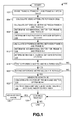
- FIG. 1 shows a flow diagram depicting a method 100 for finding a video signature according to one embodiment of this disclosure.
- Method 100 may be executed by a computing device capable of video playback and/or video streaming.
- Example computing devices include but are not limited to desktop computers, laptop computers, mobile computing devices, and TV set-top boxes.
- the computing device may further be connected to other computing devices over a network for receiving video streams and/or accessing a video signature database, which will be described in more detail below. Further detail about the computing device will be described with reference to FIG. 5 .
- method 100 includes dividing frames within the video into a plurality of cells.
- Each frame of a series of frame N, frame N+1, and frame N-1 are divided into M cells.
- M cells may include 16 equal sized cells arranged in a four by four (4x4) grid.
- M cells may include 25 equal sized cells arranged in a five-by-five grid. Any number of cells in any arrangement is within the scope of this disclosure.
- a video attribute for each cell is calculated at 104.
- the video attribute is an average luminance for that cell, calculated by averaging the luminance values for each pixel within the cell.
- the video attribute may be an average luminance for that cell normalized with respect to an average luminance for all cells of that frame.
- Other suitable attributes could be used, such as rank order of the luminance of each cell, an average color value, etc.
- a first difference metric is calculated between frame N and frame N+1.
- the difference metric may be a Euclidean distance between a vector calculated for frame N and a vector calculated for frame N+1.
- an M-dimensional vector for each of frame N and frame N+1 is determined at 108.
- the M-dimensional vector for each frame includes, for each different dimension, a video attribute of a different cell from that frame.
- FIG. 2 shows a frame N of a video divided into a 4x4 grid including 16 cells (i.e., cell N1, N2, ... N16).
- table 204 of FIG. 2 shows a luminance value for each cell of frame N.
- the average luminance is calculated from the luminance value for each pixel of that cell.
- luminance is represented by a scale from 0 to 1, where 0 is no luminance (i.e. the cell is all black and no light is emitted) and 1 is the maximum luminance (i.e. the cell is all white and the maximum amount of light the pixels can emit is being emitted).
- cell N1 has a luminance value of 0.2.
- the M-dimensional vector may include a 16-dimensional vector based on the luminance for each of the 16 cells of the divided frame.
- method 100 includes calculating a Euclidean distance between the vectors.
- a second difference metric is calculated between frame N and frame N-1 at 112. Similar to the difference metric calculated at 106, an M-dimensional vector is determined for each frame N and frame N-1 at 114, and these vectors are used to determine a second Euclidean distance at 116.
- the first difference metric calculated between frames N and N+1 is compared to a first threshold. If the first difference metric is above the first threshold, the method proceeds to 120. If it is not above the threshold, the method advances to 128.
- the second difference metric is compared to a second threshold at 120. If the second difference metric is below the second threshold, the method proceeds to 122, and if it is not below the threshold, the method advances to 128.
- the first and second thresholds for comparing the first and second difference metrics may be similar. Alternatively, the two thresholds may be different. The thresholds may be determined empirically or by any suitable mechanism.
- a 16-dimensional vector based on the luminance values in table 202 would be the same as the vector for frame N, as the frames depict the same image. Therefore, the Euclidean distance, calculated using the same equation as described above, would result in a distance of 0 between frames N and N-1.
- the calculated Euclidean distances can each be compared to a threshold.
- the first and second thresholds are equal, and empirically determined to be equal to one.
- the distance from frame N to frame N+1, ⁇ N ⁇ N +1 1.21, which is greater than the first threshold of 1.
- the distance from frame N to frame N-1, ⁇ N ⁇ N -1 0, which is less than the second threshold, which is also 1 in this case.
- a shot change is identified.
- information from one or both of frame N and frame N+1 is included as a video signature.
- the vector of frame N may be concatenated with the vector of frame N+1 at 124 to generate the signature, in this embodiment a 32-dimensional vector based on the luminance values for frame N and frame N+1.
- the signature is associated with a timestamp indicating the time relative to the start of the video at which the shot change occurs.
- the signature may then be submitted to a database of predetermined signatures, and/or the signature may be entered into a search index to search for a matching reference signature.
- the signature may be submitted to a reference video signature database along with the identifying information for use at a later time, such as when searching the database for a match to an unknown video.
- the signature generated may be entered into a search index to search for a matching signature contained within a known reference video from the reference video signature database.
- Method 100 may proceed to iteratively test subsequent frames if it is determined at 128 that the testing should continue to identify other signatures within the video. Virtually any criteria may be used to determine if additional testing should continue. For example, such testing may continue unless the end of the video has been reached or a user indicates that testing should be terminated. If the testing is to continue, the method advances one frame at 130, and loops back to the beginning of method 100. Additionally, if either of the first or second difference metrics does not meet its respective condition relative to the thresholds at 118 and 120, one frame may be advanced and the method may iteratively test subsequent frames. It should be understood that some steps for subsequent testing may not need to be repeated from previous testing. For example, if one of the tested frames has already been divided and an M-dimensional matrix has been found for that frame, such dividing and calculating need not be repeated.
- the method ends.
- the difference metric between frame N and frame N-1 may be calculated before, after, or concurrently to the calculation of the difference metric between frame N and frame N+1.
- comparing the first difference metric to the threshold may occur before, after, or concurrently to the comparison of the second difference metric to the threshold.
- shot changes may be identified even when manipulations have been made to the video. For example, it is common in videos distributed over the internet for the contrast, brightness, etc. to be altered from the original video source. By utilizing an average luminance for each cell normalized to the average luminance for the entire frame, differences in relative brightness may be accounted for. Furthermore, the identification of shot changes is not dependent on the timing of the video, so that videos that have been sped up or slowed down may also be identified. Finally, clips of videos may also be identified, so long as the clip contains at least one shot change.
- the process of identifying shot changes and creating signatures can be performed on video content that contains identifying information as well as video content that does not contain identifying information.
- Video signatures from a known video can be associated with that video in a reference database.
- One example method for searching such a database includes locality sensitive hashing.
- each reference signature is given a code, termed a hash code, and each hash code is distributed into buckets of a hash table.
- the unknown video signature, or client signature is also given a hash code.
- the bucket the client signature is distributed to reasonably contains only those reference signatures similar to the client signature. From these, a difference metric, such as a Euclidean distance, may be calculated between the client signature and the references signatures.
- method 300 includes generating a set of n random vectors (v 1 , v 2 ... v n ), the components of which should be independent and identically distributed normal random variables.
- the n random vectors may be generated once, and the set may be used for determining a hash code at 304 for every signature generated.
- the following nonlimiting example will be described with reference to a 32-dimensional vector corresponding to frames divided into 4x4 grids.
- a hash H i is determined at 306 for each random vector.
- the hash may then be converted to binary to get a hash code.
- Method 300 includes, at 312, indexing each super hash code into a bucket of a reference hash table along with tags, such as a timestamp from the video where the signature occurs, title of video, etc. If more reference signatures are to be hashed at 314, the process repeats itself.
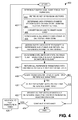
- FIG. 4 depicts a flow diagram showing an embodiment of a method 400 for entering an unknown, or client, signature into a search index to find a matching reference signature.
- the method 400 includes determining a query hash code for the client signature at 402. Similar to the method described in reference to FIG. 3 , a hash is determined at 406 based on the client signature, random vector (retrieved at 404 from the set generated at 302), and bucket size, for each random vector of the set. Each hash code is converted to binary at 408, and all binary hash codes are concatenated at 410 to produce a query super hash code for the client signature, H'.
- the query super hash code H' is assigned to a bucket of the reference hash table, and all reference hashes stored in that bucket are returned at 412.
- a difference metric such as a Euclidean distance
- a difference metric can be calculated at 414 between the client signature and each reference signature in the bucket.
- all reference signatures that have Euclidean distances below a threshold may be returned as a match. If no matches exist at 418, the method may proceed to 424. If more than one match exists at 420, the signature may be deemed to derive from common content, such as a commercial, or be a low quality signature, and thus the method may advance to 424. If it is determined at 418 and 420 that only one match exists, there is a high probability the client signature and reference signature are from the same video.
- method 400 includes determining if it is necessary to continue searching signatures within the video for more matches. For example, it may be necessary to keep searching for matches to additional client signatures within the video if no matches could initially be found, or if multiple matches were found. If it is determined that searching should be continued, the method 400 advances a next signature in the video at 426 and loops back to the beginning of method 400.
- accuracy of the matching beyond the difference metric between the client signature and the reference signature may be increased. This can be accomplished by verifying that more than one client signature in the video matches a reference signature from that video. Further, if multiple matching signatures are found between the known and unknown video, the accuracy can be further verified by correlating the difference between the timestamps from two signatures in the reference video vs. the difference between the timestamps of the same two signatures of the client video. As explained above with regard to FIG. 1 , timestamps may be associated with the video signatures. As the client video content may be altered compared to the reference video, using an absolute time correlation may not be an accurate method of verification, as the client video may be shortened, or include extra video information.
- a first video signature of a reference video may be associated with timestamp 1:35 and a second signature of that video may be associated with 1:50.
- a difference between the two is 0:15. If the client video has a signature that matches the first reference signature with a timestamp of 2:15 and a second signature that matches the second reference signature with a timestamp of 2:30, there is a high likelihood that the matches are accurate, as there are two matching signatures, and the differences between the timestamps of the signatures are the same.
- the above described methods and processes may be tied to a computing system including one or more computers.
- the methods and processes described herein may be implemented as a computer application, computer service, computer API, computer library, and/or other computer program product.
- FIG. 5 schematically shows a nonlimiting computing system 502 that may perform one or more of the above described methods and processes.
- Computing system 502 is shown in simplified form. It is to be understood that virtually any computer architecture may be used without departing from the scope of this disclosure.
- computing system 502 may take the form of a mainframe computer, server computer, desktop computer, laptop computer, tablet computer, home entertainment computer, network computing device, mobile computing device, mobile communication device, gaming device, etc.
- Computing system 502 includes a logic subsystem 504 and a data-holding subsystem 506.
- Computing system 502 may optionally include a display subsystem 508, communication subsystem 510, and/or other components not shown in FIG. 5 .
- Computing system 502 may also optionally include user input devices 512 such as keyboards, mice, game controllers, cameras, microphones, and/or touch screens, for example.
- Computing system 502 may be configured to communicate with a remote computing device such as a server 514 over a network 516. Similar to computing system 502, server 514 includes a logic subsystem 518 and a data-holding subsystem 520. Server 514 may send video streams to computing system 502 for viewing by a user. The video streams, if they lack identifying information, may be searched for video signatures, as described with reference to FIGS. 1 and 2 . Furthermore, server 514, or another server, may search reference videos for video signatures and also may utilize a reference signature database 522 for storing tagged reference signatures. Alternatively, a reference signature database 524 may be stored remotely from the server, and the server may access the database over the network.
- server 514 may be split up into a distributed network of servers.
- a load balancer which communicates with computing system 502, and delegates signature matching to one of several servers depending on the hash value for the incoming signature match request.
- Each server would host a subset of the database corresponding to certain hash buckets from the hash table. There could optionally be overlap in which hash buckets each server holds, but each hash bucket will be held by some server, so that the entire hash table is represented throughout the distributed system.
- Logic subsystem 504 may include one or more physical devices configured to execute one or more instructions.
- the logic subsystem may be configured to execute one or more instructions that are part of one or more applications, services, programs, routines, libraries, objects, components, data structures, or other logical constructs.
- Such instructions may be implemented to perform a task, implement a data type, transform the state of one or more devices, or otherwise arrive at a desired result.
- the logic subsystem may include one or more processors that are configured to execute software instructions. Additionally or alternatively, the logic subsystem may include one or more hardware or firmware logic machines configured to execute hardware or firmware instructions. Processors of the logic subsystem may be single core or multicore, and the programs executed thereon may be configured for parallel or distributed processing. The logic subsystem may optionally include individual components that are distributed throughout two or more devices, which may be remotely located and/or configured for coordinated processing. One or more aspects of the logic subsystem may be virtualized and executed by remotely accessible networked computing devices configured in a cloud computing configuration.
- Data-holding subsystem 506 may include one or more physical, non-transitory, devices configured to hold data and/or instructions executable by the logic subsystem to implement the herein described methods and processes. When such methods and processes are implemented, the state of data-holding subsystem 506 may be transformed (e.g., to hold different data).
- Data-holding subsystem 506 may include removable media and/or built-in devices.
- Data-holding subsystem 506 may include optical memory devices (e.g., CD, DVD, HD-DVD, Blu-Ray Disc, etc.), semiconductor memory devices (e.g., RAM, EPROM, EEPROM, etc.) and/or magnetic memory devices (e.g., hard disk drive, floppy disk drive, tape drive, MRAM, etc.), among others.
- Data-holding subsystem 506 may include devices with one or more of the following characteristics: volatile, nonvolatile, dynamic, static, read/write, read-only, random access, sequential access, location addressable, file addressable, and content addressable.
- logic subsystem 504 and data-holding subsystem 506 may be integrated into one or more common devices, such as an application specific integrated circuit or a system on a chip.
- FIG. 5 also shows an aspect of the data-holding subsystem in the form of removable computer-readable storage media 526, which may be used to store and/or transfer data and/or instructions executable to implement the herein described methods and processes.
- Removable computer-readable storage media 526 may take the form of CDs, DVDs, HD-DVDs, Blu-Ray Discs, EEPROMs, and/or floppy disks, among others.
- data-holding subsystem 506 includes one or more physical, non-transitory devices.
- aspects of the instructions described herein may be propagated in a transitory fashion by a pure signal (e.g., an electromagnetic signal, an optical signal, etc.) that is not held by a physical device for at least a finite duration.
- a pure signal e.g., an electromagnetic signal, an optical signal, etc.
- data and/or other forms of information pertaining to the present disclosure may be propagated by a pure signal.
- module may be used to describe an aspect of computing system 502 that is implemented to perform one or more particular functions.
- a module, program, or engine may be instantiated via logic subsystem 504 executing instructions held by data-holding subsystem 506.
- different modules, programs, and/or engines may be instantiated from the same application, service, code block, object, library, routine, API, function, etc.
- the same module, program, and/or engine may be instantiated by different applications, services, code blocks, objects, routines, APIs, functions, etc.
- module module, program,” and “engine” are meant to encompass individual or groups of executable files, data files, libraries, drivers, scripts, database records, etc.
- a "service”, as used herein, may be an application program executable across multiple user sessions and available to one or more system components, programs, and/or other services.
- a service may run on a server responsive to a request from a client.
- display subsystem 508 may be used to present a visual representation of data held by data-holding subsystem 506. As the herein described methods and processes change the data held by the data-holding subsystem, and thus transform the state of the data-holding subsystem, the state of display subsystem 508 may likewise be transformed to visually represent changes in the underlying data.
- Display subsystem 508 may include one or more display devices utilizing virtually any type of technology. Such display devices may be combined with logic subsystem 504 and/or data-holding subsystem 506 in a shared enclosure, or such display devices may be peripheral display devices.
- communication subsystem 510 may be configured to communicatively couple computing system 502 with one or more other computing devices, such as server 514.
- Communication subsystem 510 may include wired and/or wireless communication devices compatible with one or more different communication protocols.
- the communication subsystem may be configured for communication via a wireless telephone network, a wireless local area network, a wired local area network, a wireless wide area network, a wired wide area network, etc.
- the communication subsystem may allow computing system 502 to send and/or receive messages to and/or from other devices via a network such as the Internet.
Description
- Identification information, such as metadata, is often not included with digital video content. Often this results in a viewer being unable to identify the title, year of production, genre of content, or any other information he or she may desire for a satisfactory viewing experience.
- In "Scene change Detection Algorithms for Content-Based Video Indexing and Retrieval", Electronics and Communication Engineering Journal, Institution of Electrical Engineers, London, GB, vol. 13, no. 3, 1 June 2001, pages 117-128, Fernando W. A. C. et al. describe that abrupt shot transitions are very easy to detect as two frames being compared are completely uncorrelated. Most previous work on detecting a sudden scene change is based on entire images and uses difference metrics to evaluate the changes between successive frames. Zhang proposed that a change between two frames could be detected by comparing the difference in the intensity values of corresponding pixels in the two frames. In a likelihood ratio approach, the frames are subdivided into blocks, which are then compared on the basis of statistical characteristics of their intensity levels.
- In "Video fingerprinting for copy identification: from research to industry applications", Proceedings of SPIE, SPIE- International Society for Optical Engineering, US, vol. 7254, 19 January 2009, pages 725402-1, Jian Lu describes temporal signatures. A video sequence is segmented into shots. Then, the duration of each shot is taken as a temporal signature, and the sequence of concatenated shot durations form the fingerprint of the video. Temporal signatures are computed on adjacent frames in a video. A frame is subdivided into a fixed-sized grid of blocks, and the average pixel value of each block is computed.
- This Summary is provided to introduce a selection of concepts in a simplified form that are further described below in the Detailed Description. This Summary is not intended to identify key features or essential features of the claimed subject matter, nor is it intended to be used to limit the scope of the claimed subject matter. Furthermore, the claimed subject matter is not limited to implementations that solve any or all disadvantages noted in any part of this disclosure.
- A method for finding a video signature is provided. The method comprises dividing each of frame N, frame N+1, and frame N-1 of the video into a plurality of cells and calculating a video attribute for each cell of each frame. A difference metric is calculated between frames N and N+1 and frames N and N-1 based on the video attributes of each frame, and the difference metrics are compared to a threshold. If the difference metric of frames N and N+1 exceeds a first threshold and a difference metric between frames N and N-1 does not exceed a second threshold, information from frame N and frame N+1 is used as a video signature.
-
-
FIG. 1 is a flow diagram depicting a method for finding a signature of a video stream according to one embodiment of the present disclosure. -
FIG. 2 schematically shows frames from a video and associated luminance values according to one embodiment disclosed herein. -
FIG. 3 is a flow diagram depicting an example embodiment for entering reference signatures into a search index database. -
FIG. 4 is a flow diagram depicting an example embodiment for entering a client signature into a search index. -
FIG. 5 schematically shows a non-limiting computing device for executing the embodiments disclosed herein. - The playback of media content, such as digital video, that lacks external identifying information may present problems, as the title of the video, the date it was produced, and other information may be needed by a viewer for a satisfactory viewing experience. To locate identifying information for an unknown video, video signatures may be generated by identifying shot changes within the video. Shot changes may be defined by a large change in the image information between two consecutive frames N and N+1 of the video, along with a small change in the image information between frame N and the preceding frame N-1. Information from the shot change can then be used to generate a video signature. The video signature may be easily reproducible on different versions of the same video.
- Such a video signature may be compared to a video signature database that includes video signatures for a library of reference videos, as well as identifying information (e.g., metadata) for each such reference video. If a match is found, the external identifying information from the matching reference video can be applied to the unknown video. In some embodiments, a Euclidean distance between the tested signature and the reference signature may be used to determine whether a match exists. In some embodiments, such a Euclidean distance must be zero, and in other embodiments a small difference may be allowed.
-
FIG. 1 shows a flow diagram depicting amethod 100 for finding a video signature according to one embodiment of this disclosure.Method 100 may be executed by a computing device capable of video playback and/or video streaming. Example computing devices include but are not limited to desktop computers, laptop computers, mobile computing devices, and TV set-top boxes. The computing device may further be connected to other computing devices over a network for receiving video streams and/or accessing a video signature database, which will be described in more detail below. Further detail about the computing device will be described with reference toFIG. 5 . - At 102,
method 100 includes dividing frames within the video into a plurality of cells. Each frame of a series of frame N, frame N+1, and frame N-1 are divided into M cells. In one example, M cells may include 16 equal sized cells arranged in a four by four (4x4) grid. In another example, M cells may include 25 equal sized cells arranged in a five-by-five grid. Any number of cells in any arrangement is within the scope of this disclosure. - A video attribute for each cell is calculated at 104. In some embodiments, the video attribute is an average luminance for that cell, calculated by averaging the luminance values for each pixel within the cell. In some embodiments, the video attribute may be an average luminance for that cell normalized with respect to an average luminance for all cells of that frame. Other suitable attributes could be used, such as rank order of the luminance of each cell, an average color value, etc.
- At 106, a first difference metric is calculated between frame N and frame N+1. As an example, the difference metric may be a Euclidean distance between a vector calculated for frame N and a vector calculated for frame N+1. To calculate this difference metric, an M-dimensional vector for each of frame N and frame N+1 is determined at 108. The M-dimensional vector for each frame includes, for each different dimension, a video attribute of a different cell from that frame.
- For example,
FIG. 2 shows a frame N of a video divided into a 4x4 grid including 16 cells (i.e., cell N1, N2, ... N16). Furthermore, table 204 ofFIG. 2 shows a luminance value for each cell of frame N. For each cell, the average luminance is calculated from the luminance value for each pixel of that cell. In this example, luminance is represented by a scale from 0 to 1, where 0 is no luminance (i.e. the cell is all black and no light is emitted) and 1 is the maximum luminance (i.e. the cell is all white and the maximum amount of light the pixels can emit is being emitted). For example, cell N1 has a luminance value of 0.2. The M-dimensional vector may include a 16-dimensional vector based on the luminance for each of the 16 cells of the divided frame. For example, frame N would have a 16-dimensional vector comprising:
luminance values 206, would have a 16-dimensional vector comprising:
- Turning back to
FIG. 1 , at 110,method 100 includes calculating a Euclidean distance between the vectors. For example, inFIG. 2 , the Euclidean distance between frame N and frame N+1 ofFIG. 2 may be calculated using the following equation:
FIG. 2 would be approximately 1.21. - Referring back to
FIG. 1 , a second difference metric is calculated between frame N and frame N-1 at 112. Similar to the difference metric calculated at 106, an M-dimensional vector is determined for each frame N and frame N-1 at 114, and these vectors are used to determine a second Euclidean distance at 116. - At 118, the first difference metric calculated between frames N and N+1 is compared to a first threshold. If the first difference metric is above the first threshold, the method proceeds to 120. If it is not above the threshold, the method advances to 128. The second difference metric is compared to a second threshold at 120. If the second difference metric is below the second threshold, the method proceeds to 122, and if it is not below the threshold, the method advances to 128. The first and second thresholds for comparing the first and second difference metrics may be similar. Alternatively, the two thresholds may be different. The thresholds may be determined empirically or by any suitable mechanism.
- Referring to the example frames depicted in
FIG. 2 , for frame N-1, a 16-dimensional vector based on the luminance values in table 202 would be the same as the vector for frame N, as the frames depict the same image. Therefore, the Euclidean distance, calculated using the same equation as described above, would result in a distance of 0 between frames N and N-1. - In order to determine if the frames constitute a shot change, the calculated Euclidean distances can each be compared to a threshold. In this example, the first and second thresholds are equal, and empirically determined to be equal to one. Thus, the distance from frame N to frame N+1, Δ N→N+1 = 1.21, which is greater than the first threshold of 1. The distance from frame N to frame N-1, Δ N→N-1= 0, which is less than the second threshold, which is also 1 in this case. As the first distance is greater than the threshold and the second is not, a shot change is identified.
- At 122 in
FIG. 1 , information from one or both of frame N and frame N+1 is included as a video signature. The vector of frame N may be concatenated with the vector of frame N+1 at 124 to generate the signature, in this embodiment a 32-dimensional vector based on the luminance values for frame N and frame N+1. At 126, the signature is associated with a timestamp indicating the time relative to the start of the video at which the shot change occurs. The signature may then be submitted to a database of predetermined signatures, and/or the signature may be entered into a search index to search for a matching reference signature. For example, if the video is a known video that contains identifying information, the signature may be submitted to a reference video signature database along with the identifying information for use at a later time, such as when searching the database for a match to an unknown video. Alternatively, if the video is an unknown video that does not contain identifying information, the signature generated may be entered into a search index to search for a matching signature contained within a known reference video from the reference video signature database. -
Method 100 may proceed to iteratively test subsequent frames if it is determined at 128 that the testing should continue to identify other signatures within the video. Virtually any criteria may be used to determine if additional testing should continue. For example, such testing may continue unless the end of the video has been reached or a user indicates that testing should be terminated. If the testing is to continue, the method advances one frame at 130, and loops back to the beginning ofmethod 100. Additionally, if either of the first or second difference metrics does not meet its respective condition relative to the thresholds at 118 and 120, one frame may be advanced and the method may iteratively test subsequent frames. It should be understood that some steps for subsequent testing may not need to be repeated from previous testing. For example, if one of the tested frames has already been divided and an M-dimensional matrix has been found for that frame, such dividing and calculating need not be repeated. - Alternatively, if it is determined the testing should not continue (e.g. if all signatures in the video have been identified) the method ends.
- It should be understood that the
method 100 need not be carried out in the order described. For example, the difference metric between frame N and frame N-1 may be calculated before, after, or concurrently to the calculation of the difference metric between frame N and frame N+1. Similarly, comparing the first difference metric to the threshold may occur before, after, or concurrently to the comparison of the second difference metric to the threshold. - By using average luminance values of a grid of even sized cells, shot changes may be identified even when manipulations have been made to the video. For example, it is common in videos distributed over the internet for the contrast, brightness, etc. to be altered from the original video source. By utilizing an average luminance for each cell normalized to the average luminance for the entire frame, differences in relative brightness may be accounted for. Furthermore, the identification of shot changes is not dependent on the timing of the video, so that videos that have been sped up or slowed down may also be identified. Finally, clips of videos may also be identified, so long as the clip contains at least one shot change.
- The process of identifying shot changes and creating signatures can be performed on video content that contains identifying information as well as video content that does not contain identifying information. Video signatures from a known video can be associated with that video in a reference database. One example method for searching such a database includes locality sensitive hashing. In this method, each reference signature is given a code, termed a hash code, and each hash code is distributed into buckets of a hash table. The unknown video signature, or client signature, is also given a hash code. The bucket the client signature is distributed to reasonably contains only those reference signatures similar to the client signature. From these, a difference metric, such as a Euclidean distance, may be calculated between the client signature and the references signatures.
- An
example method 300 of generating hash codes for reference video signatures is described with reference toFIG. 3 . At 302,method 300 includes generating a set of n random vectors (v1, v2 ... v n ), the components of which should be independent and identically distributed normal random variables. The n random vectors may be generated once, and the set may be used for determining a hash code at 304 for every signature generated. The following nonlimiting example will be described with reference to a 32-dimensional vector corresponding to frames divided into 4x4 grids. - A hash H i is determined at 306 for each random vector. Each H i may be calculated using the following equation:

Method 300 includes, at 312, indexing each super hash code into a bucket of a reference hash table along with tags, such as a timestamp from the video where the signature occurs, title of video, etc. If more reference signatures are to be hashed at 314, the process repeats itself. -
FIG. 4 depicts a flow diagram showing an embodiment of amethod 400 for entering an unknown, or client, signature into a search index to find a matching reference signature. Themethod 400 includes determining a query hash code for the client signature at 402. Similar to the method described in reference toFIG. 3 , a hash is determined at 406 based on the client signature, random vector (retrieved at 404 from the set generated at 302), and bucket size, for each random vector of the set. Each hash code is converted to binary at 408, and all binary hash codes are concatenated at 410 to produce a query super hash code for the client signature, H'. The query super hash code H' is assigned to a bucket of the reference hash table, and all reference hashes stored in that bucket are returned at 412. A difference metric, such as a Euclidean distance, can be calculated at 414 between the client signature and each reference signature in the bucket. At 416, all reference signatures that have Euclidean distances below a threshold may be returned as a match. If no matches exist at 418, the method may proceed to 424. If more than one match exists at 420, the signature may be deemed to derive from common content, such as a commercial, or be a low quality signature, and thus the method may advance to 424. If it is determined at 418 and 420 that only one match exists, there is a high probability the client signature and reference signature are from the same video. In this case, the client video may be identified as the reference video at 422, and the information accompanying the reference video, such as title, date, etc., may be added to the client video. At 424,method 400 includes determining if it is necessary to continue searching signatures within the video for more matches. For example, it may be necessary to keep searching for matches to additional client signatures within the video if no matches could initially be found, or if multiple matches were found. If it is determined that searching should be continued, themethod 400 advances a next signature in the video at 426 and loops back to the beginning ofmethod 400. - Additionally, accuracy of the matching beyond the difference metric between the client signature and the reference signature may be increased. This can be accomplished by verifying that more than one client signature in the video matches a reference signature from that video. Further, if multiple matching signatures are found between the known and unknown video, the accuracy can be further verified by correlating the difference between the timestamps from two signatures in the reference video vs. the difference between the timestamps of the same two signatures of the client video. As explained above with regard to
FIG. 1 , timestamps may be associated with the video signatures. As the client video content may be altered compared to the reference video, using an absolute time correlation may not be an accurate method of verification, as the client video may be shortened, or include extra video information. However, if the difference between two timestamps is used, an accurate correlation may be made. For example, a first video signature of a reference video may be associated with timestamp 1:35 and a second signature of that video may be associated with 1:50. In this example a difference between the two is 0:15. If the client video has a signature that matches the first reference signature with a timestamp of 2:15 and a second signature that matches the second reference signature with a timestamp of 2:30, there is a high likelihood that the matches are accurate, as there are two matching signatures, and the differences between the timestamps of the signatures are the same. - In some embodiments, the above described methods and processes may be tied to a computing system including one or more computers. In particular, the methods and processes described herein may be implemented as a computer application, computer service, computer API, computer library, and/or other computer program product.
-
FIG. 5 schematically shows anonlimiting computing system 502 that may perform one or more of the above described methods and processes.Computing system 502 is shown in simplified form. It is to be understood that virtually any computer architecture may be used without departing from the scope of this disclosure. In different embodiments,computing system 502 may take the form of a mainframe computer, server computer, desktop computer, laptop computer, tablet computer, home entertainment computer, network computing device, mobile computing device, mobile communication device, gaming device, etc. -
Computing system 502 includes alogic subsystem 504 and a data-holdingsubsystem 506.Computing system 502 may optionally include adisplay subsystem 508,communication subsystem 510, and/or other components not shown inFIG. 5 .Computing system 502 may also optionally includeuser input devices 512 such as keyboards, mice, game controllers, cameras, microphones, and/or touch screens, for example. -
Computing system 502 may be configured to communicate with a remote computing device such as aserver 514 over anetwork 516. Similar tocomputing system 502,server 514 includes alogic subsystem 518 and a data-holdingsubsystem 520.Server 514 may send video streams tocomputing system 502 for viewing by a user. The video streams, if they lack identifying information, may be searched for video signatures, as described with reference toFIGS. 1 and2 . Furthermore,server 514, or another server, may search reference videos for video signatures and also may utilize areference signature database 522 for storing tagged reference signatures. Alternatively, areference signature database 524 may be stored remotely from the server, and the server may access the database over the network. - Because of the distributed nature of a hash table, the duties of
server 514 may be split up into a distributed network of servers. In this case, there would be a load balancer which communicates withcomputing system 502, and delegates signature matching to one of several servers depending on the hash value for the incoming signature match request. Each server would host a subset of the database corresponding to certain hash buckets from the hash table. There could optionally be overlap in which hash buckets each server holds, but each hash bucket will be held by some server, so that the entire hash table is represented throughout the distributed system. -
Logic subsystem 504 may include one or more physical devices configured to execute one or more instructions. For example, the logic subsystem may be configured to execute one or more instructions that are part of one or more applications, services, programs, routines, libraries, objects, components, data structures, or other logical constructs. Such instructions may be implemented to perform a task, implement a data type, transform the state of one or more devices, or otherwise arrive at a desired result. - The logic subsystem may include one or more processors that are configured to execute software instructions. Additionally or alternatively, the logic subsystem may include one or more hardware or firmware logic machines configured to execute hardware or firmware instructions. Processors of the logic subsystem may be single core or multicore, and the programs executed thereon may be configured for parallel or distributed processing. The logic subsystem may optionally include individual components that are distributed throughout two or more devices, which may be remotely located and/or configured for coordinated processing. One or more aspects of the logic subsystem may be virtualized and executed by remotely accessible networked computing devices configured in a cloud computing configuration.
- Data-holding
subsystem 506 may include one or more physical, non-transitory, devices configured to hold data and/or instructions executable by the logic subsystem to implement the herein described methods and processes. When such methods and processes are implemented, the state of data-holdingsubsystem 506 may be transformed (e.g., to hold different data). - Data-holding
subsystem 506 may include removable media and/or built-in devices. Data-holdingsubsystem 506 may include optical memory devices (e.g., CD, DVD, HD-DVD, Blu-Ray Disc, etc.), semiconductor memory devices (e.g., RAM, EPROM, EEPROM, etc.) and/or magnetic memory devices (e.g., hard disk drive, floppy disk drive, tape drive, MRAM, etc.), among others. Data-holdingsubsystem 506 may include devices with one or more of the following characteristics: volatile, nonvolatile, dynamic, static, read/write, read-only, random access, sequential access, location addressable, file addressable, and content addressable. In some embodiments,logic subsystem 504 and data-holdingsubsystem 506 may be integrated into one or more common devices, such as an application specific integrated circuit or a system on a chip. -
FIG. 5 also shows an aspect of the data-holding subsystem in the form of removable computer-readable storage media 526, which may be used to store and/or transfer data and/or instructions executable to implement the herein described methods and processes. Removable computer-readable storage media 526 may take the form of CDs, DVDs, HD-DVDs, Blu-Ray Discs, EEPROMs, and/or floppy disks, among others. - It is to be appreciated that data-holding
subsystem 506 includes one or more physical, non-transitory devices. In contrast, in some embodiments aspects of the instructions described herein may be propagated in a transitory fashion by a pure signal (e.g., an electromagnetic signal, an optical signal, etc.) that is not held by a physical device for at least a finite duration. Furthermore, data and/or other forms of information pertaining to the present disclosure may be propagated by a pure signal. - The terms "module," "program," and "engine" may be used to describe an aspect of
computing system 502 that is implemented to perform one or more particular functions. In some cases, such a module, program, or engine may be instantiated vialogic subsystem 504 executing instructions held by data-holdingsubsystem 506. It is to be understood that different modules, programs, and/or engines may be instantiated from the same application, service, code block, object, library, routine, API, function, etc. Likewise, the same module, program, and/or engine may be instantiated by different applications, services, code blocks, objects, routines, APIs, functions, etc. The terms "module," "program," and "engine" are meant to encompass individual or groups of executable files, data files, libraries, drivers, scripts, database records, etc. - It is to be appreciated that a "service", as used herein, may be an application program executable across multiple user sessions and available to one or more system components, programs, and/or other services. In some implementations, a service may run on a server responsive to a request from a client.
- When included,
display subsystem 508 may be used to present a visual representation of data held by data-holdingsubsystem 506. As the herein described methods and processes change the data held by the data-holding subsystem, and thus transform the state of the data-holding subsystem, the state ofdisplay subsystem 508 may likewise be transformed to visually represent changes in the underlying data.Display subsystem 508 may include one or more display devices utilizing virtually any type of technology. Such display devices may be combined withlogic subsystem 504 and/or data-holdingsubsystem 506 in a shared enclosure, or such display devices may be peripheral display devices. - When included,
communication subsystem 510 may be configured to communicatively couplecomputing system 502 with one or more other computing devices, such asserver 514.Communication subsystem 510 may include wired and/or wireless communication devices compatible with one or more different communication protocols. As nonlimiting examples, the communication subsystem may be configured for communication via a wireless telephone network, a wireless local area network, a wired local area network, a wireless wide area network, a wired wide area network, etc. In some embodiments, the communication subsystem may allowcomputing system 502 to send and/or receive messages to and/or from other devices via a network such as the Internet. - It is to be understood that the configurations and/or approaches described herein are exemplary in nature, and that these specific embodiments or examples are not to be considered in a limiting sense, because numerous variations are possible. The specific routines or methods described herein may represent one or more of any number of processing strategies. As such, various acts illustrated may be performed in the sequence illustrated, in other sequences, in parallel, or in some cases omitted. Likewise, the order of the above-described processes may be changed.
- The subject matter of the present disclosure includes all novel and nonobvious combinations and subcombinations of the various processes, systems and configurations, and other features, functions, acts, and/or properties disclosed herein, as well as any and all equivalents thereof.
Claims (8)
- A method (100) of generating a signature for a video, the method comprising:iteratively testing (130) a series of three consecutive frames N-1, N, N+1 within the video, each test comprising:dividing (102) a frame N of the video into a plurality of cells;calculating (104) a video attribute of each cell of frame N;dividing (102) a frame N+1 into the plurality of cells;calculating (104) a video attribute of each cell of frame N+1;calculating (106) a difference metric between frame N and frame N+1 that includes, for each cell of the plurality of cells, a difference between the video attribute of frame N and the video attribute of frame N+1;if the difference metric between frame N and frame N+1 exceeds (118-YES) a first threshold and a difference metric between frame N and frame N-1 does not exceed (120-YES) a second threshold, generating (122) a video signature by concatenating (124) each of the video attributes of frame N with each of the video attributes of frame N+1,wherein the video attribute is one of: an average luminance for that cell, an average luminance for that cell normalized with respect to an average luminance for all cells of that frame, a rank order of the luminance of each cell and an average color value.
- The method (100) of claim 1, wherein the plurality of cells includes M cells, and where an M-dimensional vector for each frame includes the video attribute for each of the plurality of M cells.
- The method (100) of claim 2, wherein calculating (106) the difference metric between frame N and frame N+1 includes calculating (110) a Euclidean distance between the M-dimensional vector for frame N and the M-dimensional vector for frame N+1.
- The method (100) of any one of the preceding claims, wherein dividing (102) the frame N of the video into a plurality of cells includes dividing (102) the frame N into a four by four grid of cells.
- The method (100) of any one of the preceding claims, wherein frame N-1 is divided (102) into M cells and an M-dimensional vector for frame N-1 includes the video attribute for each cell, and wherein calculating (114) the difference metric between frame N and frame N-1 includes calculating (116) a Euclidean distance between the M-dimensional vector for frame N and the M-dimensional vector for frame N-1.
- The method (100) of any one of the preceding claims, wherein generating the video signature further comprises associating (126) a timestamp with the video signature.
- The method (100) of any one of the preceding claims, further comprising submitting the video signature into a database and/or search index.
- A data-holding subsystem (506, 526) holding instructions executable by a logic subsystem (504) that, when executed by the logic subsystem (504), cause the logic subsystem (504) to perform the method (100) of any one of the preceding claims.
Applications Claiming Priority (2)
| Application Number | Priority Date | Filing Date | Title |
|---|---|---|---|
| US13/080,494 US8786785B2 (en) | 2011-04-05 | 2011-04-05 | Video signature |
| PCT/US2012/030396 WO2012138491A2 (en) | 2011-04-05 | 2012-03-23 | Video signature |
Publications (3)
| Publication Number | Publication Date |
|---|---|
| EP2695378A2 EP2695378A2 (en) | 2014-02-12 |
| EP2695378A4 EP2695378A4 (en) | 2014-09-24 |
| EP2695378B1 true EP2695378B1 (en) | 2015-08-05 |
Family
ID=46965845
Family Applications (1)
| Application Number | Title | Priority Date | Filing Date |
|---|---|---|---|
| EP12767870.4A Not-in-force EP2695378B1 (en) | 2011-04-05 | 2012-03-23 | Video signature |
Country Status (6)
| Country | Link |
|---|---|
| US (1) | US8786785B2 (en) |
| EP (1) | EP2695378B1 (en) |
| JP (1) | JP5980311B2 (en) |
| KR (1) | KR101921354B1 (en) |
| CN (1) | CN103460711B (en) |
| WO (1) | WO2012138491A2 (en) |
Families Citing this family (27)
| Publication number | Priority date | Publication date | Assignee | Title |
|---|---|---|---|---|
| KR20130020050A (en) * | 2011-08-18 | 2013-02-27 | 삼성전자주식회사 | Apparatus and method for managing bucket range of locality sensitivie hash |
| TWI538492B (en) * | 2012-10-05 | 2016-06-11 | Video clip search method | |
| MY168873A (en) * | 2012-12-07 | 2018-12-04 | Mimos Berhad | System and method for verifying authenticity of a media content |
| US9668020B2 (en) * | 2014-04-07 | 2017-05-30 | The Nielsen Company (Us), Llc | Signature retrieval and matching for media monitoring |
| US9578394B2 (en) | 2015-03-25 | 2017-02-21 | Cisco Technology, Inc. | Video signature creation and matching |
| US10015541B2 (en) * | 2015-03-25 | 2018-07-03 | Cisco Technology, Inc. | Storing and retrieval heuristics |
| WO2016151415A1 (en) * | 2015-03-25 | 2016-09-29 | Cisco Technology, Inc. | Storing and retrieval heuristics |
| KR102560635B1 (en) * | 2015-12-28 | 2023-07-28 | 삼성전자주식회사 | Content recognition device and method for controlling thereof |
| US10338916B2 (en) | 2016-12-07 | 2019-07-02 | Sap Se | Software version fingerprint generation and identification |
| CN107071577A (en) * | 2017-04-24 | 2017-08-18 | 安徽森度科技有限公司 | A kind of video transmits endorsement method |
| US20190042853A1 (en) * | 2017-08-04 | 2019-02-07 | Facebook, Inc. | System and Method of Determining Video Content |
| US10803038B2 (en) * | 2017-09-13 | 2020-10-13 | The Nielsen Company (Us), Llc | Cold matching by automatic content recognition |
| US10306333B2 (en) | 2017-09-13 | 2019-05-28 | The Nielsen Company (Us), Llc | Flagging advertisement frames for automatic content recognition |
| JP7415242B2 (en) | 2018-03-09 | 2024-01-17 | 国立研究開発法人物質・材料研究機構 | magnetic separation device |
| US10911824B2 (en) * | 2018-11-05 | 2021-02-02 | The Nielsen Company (Us), Llc | Methods and apparatus to generate reference signatures |
| WO2020152845A1 (en) * | 2019-01-25 | 2020-07-30 | 日本電気株式会社 | Security information analysis device, system, method and program |
| CN112099725A (en) * | 2019-06-17 | 2020-12-18 | 华为技术有限公司 | Data processing method and device and computer readable storage medium |
| US20210004836A1 (en) | 2019-07-05 | 2021-01-07 | Talkdesk, Inc. | System and method for pre-populating forms using agent assist within a cloud-based contact center |
| US11328205B2 (en) | 2019-08-23 | 2022-05-10 | Talkdesk, Inc. | Generating featureless service provider matches |
| US20210117882A1 (en) | 2019-10-16 | 2021-04-22 | Talkdesk, Inc | Systems and methods for workforce management system deployment |
| US20210136220A1 (en) | 2019-10-31 | 2021-05-06 | Talkdesk, Inc. | Monitoring and listening tools across omni-channel inputs in a graphically interactive voice response system |
| US11736615B2 (en) | 2020-01-16 | 2023-08-22 | Talkdesk, Inc. | Method, apparatus, and computer-readable medium for managing concurrent communications in a networked call center |
| CN112507959A (en) * | 2020-12-21 | 2021-03-16 | 中国科学院心理研究所 | Method for establishing emotion perception model based on individual face analysis in video |
| US11677875B2 (en) | 2021-07-02 | 2023-06-13 | Talkdesk Inc. | Method and apparatus for automated quality management of communication records |
| US11856140B2 (en) | 2022-03-07 | 2023-12-26 | Talkdesk, Inc. | Predictive communications system |
| US11736616B1 (en) | 2022-05-27 | 2023-08-22 | Talkdesk, Inc. | Method and apparatus for automatically taking action based on the content of call center communications |
| US11943391B1 (en) | 2022-12-13 | 2024-03-26 | Talkdesk, Inc. | Method and apparatus for routing communications within a contact center |
Family Cites Families (19)
| Publication number | Priority date | Publication date | Assignee | Title |
|---|---|---|---|---|
| US4353088A (en) * | 1980-05-14 | 1982-10-05 | Oak Industries, Inc. | Coding and decoding system for video and audio signals |
| US4739398A (en) * | 1986-05-02 | 1988-04-19 | Control Data Corporation | Method, apparatus and system for recognizing broadcast segments |
| JP3823333B2 (en) * | 1995-02-21 | 2006-09-20 | 株式会社日立製作所 | Moving image change point detection method, moving image change point detection apparatus, moving image change point detection system |
| US5870754A (en) * | 1996-04-25 | 1999-02-09 | Philips Electronics North America Corporation | Video retrieval of MPEG compressed sequences using DC and motion signatures |
| US5767923A (en) * | 1996-06-07 | 1998-06-16 | Electronic Data Systems Corporation | Method and system for detecting cuts in a video signal |
| CN1708758A (en) | 2002-11-01 | 2005-12-14 | 皇家飞利浦电子股份有限公司 | Improved audio data fingerprint searching |
| US20040240562A1 (en) | 2003-05-28 | 2004-12-02 | Microsoft Corporation | Process and system for identifying a position in video using content-based video timelines |
| AU2003272483A1 (en) | 2003-09-12 | 2005-04-27 | Nielsen Media Research, Inc. | Digital video signature apparatus and methods for use with video program identification systems |
| US7336841B2 (en) * | 2004-03-25 | 2008-02-26 | Intel Corporation | Fingerprinting digital video for rights management in networks |
| EP2126833A2 (en) * | 2006-11-30 | 2009-12-02 | Dolby Laboratories Licensing Corporation | Extracting features of video&audio signal content to provide reliable identification of the signals |
| US8655031B2 (en) | 2007-03-27 | 2014-02-18 | Sony Corporation | Video content identification using scene change signatures from downscaled images |
| ATE494587T1 (en) | 2007-05-17 | 2011-01-15 | Dolby Lab Licensing Corp | DERIVATION OF VIDEO SIGNATURES INSENSITIVE TO IMAGE EDITING AND FRAME RATE CONVERSION |
| US8442384B2 (en) | 2007-07-16 | 2013-05-14 | Michael Bronstein | Method and apparatus for video digest generation |
| US9177209B2 (en) * | 2007-12-17 | 2015-11-03 | Sinoeast Concept Limited | Temporal segment based extraction and robust matching of video fingerprints |
| JP4924447B2 (en) * | 2008-01-25 | 2012-04-25 | ソニー株式会社 | Scene switching point detector, scene switching point detection method, recording device, event generator, event generation method, and playback device |
| US20110032984A1 (en) | 2008-07-17 | 2011-02-10 | Guy Dorman | Methods circuits and systems for transmission of video |
| US8498487B2 (en) | 2008-08-20 | 2013-07-30 | Sri International | Content-based matching of videos using local spatio-temporal fingerprints |
| EP2208153B1 (en) | 2008-10-29 | 2013-12-11 | NDS Limited | Video signature |
| EP2383697A4 (en) * | 2009-01-23 | 2012-09-05 | Nec Corp | Image identifier extracting apparatus |
-
2011
- 2011-04-05 US US13/080,494 patent/US8786785B2/en not_active Expired - Fee Related
-
2012
- 2012-03-23 CN CN201280016705.1A patent/CN103460711B/en not_active Expired - Fee Related
- 2012-03-23 KR KR1020137026097A patent/KR101921354B1/en active IP Right Grant
- 2012-03-23 WO PCT/US2012/030396 patent/WO2012138491A2/en active Application Filing
- 2012-03-23 JP JP2014503677A patent/JP5980311B2/en not_active Expired - Fee Related
- 2012-03-23 EP EP12767870.4A patent/EP2695378B1/en not_active Not-in-force
Also Published As
| Publication number | Publication date |
|---|---|
| CN103460711B (en) | 2017-03-22 |
| WO2012138491A3 (en) | 2013-01-10 |
| WO2012138491A2 (en) | 2012-10-11 |
| JP2014513468A (en) | 2014-05-29 |
| EP2695378A4 (en) | 2014-09-24 |
| US20120257116A1 (en) | 2012-10-11 |
| JP5980311B2 (en) | 2016-08-31 |
| US8786785B2 (en) | 2014-07-22 |
| KR101921354B1 (en) | 2018-11-22 |
| EP2695378A2 (en) | 2014-02-12 |
| CN103460711A (en) | 2013-12-18 |
| KR20140015430A (en) | 2014-02-06 |
Similar Documents
| Publication | Publication Date | Title |
|---|---|---|
| EP2695378B1 (en) | Video signature | |
| US11080331B2 (en) | Systems and methods for addressing a media database using distance associative hashing | |
| US20210287012A1 (en) | Detection of demarcating segments in video | |
| US11949964B2 (en) | Generating action tags for digital videos | |
| JP6891170B2 (en) | Future viewing forecasts for video segments to optimize stem resource utilization | |
| US9055335B2 (en) | Systems and methods for addressing a media database using distance associative hashing | |
| US9185338B2 (en) | System and method for fingerprinting video | |
| CA2906199C (en) | Systems and methods for addressing a media database using distance associative hashing | |
| EP3001871B1 (en) | Systems and methods for addressing a media database using distance associative hashing | |
| US20190179850A1 (en) | Generating congruous metadata for multimedia | |
| US9430474B2 (en) | Automated multimedia content recognition | |
| US20110252018A1 (en) | System and method for creating search index on cloud database | |
| CN107426610B (en) | Video information synchronization method and device | |
| US8588534B2 (en) | Staged element classification | |
| JP2020525949A (en) | Media search method and device | |
| US20170357654A1 (en) | Using audio and video matching to determine age of content |
Legal Events
| Date | Code | Title | Description |
|---|---|---|---|
| PUAI | Public reference made under article 153(3) epc to a published international application that has entered the european phase |
Free format text: ORIGINAL CODE: 0009012 |
|
| 17P | Request for examination filed |
Effective date: 20130925 |
|
| AK | Designated contracting states |
Kind code of ref document: A2 Designated state(s): AL AT BE BG CH CY CZ DE DK EE ES FI FR GB GR HR HU IE IS IT LI LT LU LV MC MK MT NL NO PL PT RO RS SE SI SK SM TR |
|
| DAX | Request for extension of the european patent (deleted) | ||
| A4 | Supplementary search report drawn up and despatched |
Effective date: 20140826 |
|
| RIC1 | Information provided on ipc code assigned before grant |
Ipc: H04N 19/00 20140101ALI20140826BHEP Ipc: H04N 21/845 20110101ALI20140826BHEP Ipc: G06K 9/00 20060101ALI20140826BHEP Ipc: H04N 7/16 20110101AFI20140826BHEP |
|
| 17Q | First examination report despatched |
Effective date: 20140904 |
|
| GRAP | Despatch of communication of intention to grant a patent |
Free format text: ORIGINAL CODE: EPIDOSNIGR1 |
|
| INTG | Intention to grant announced |
Effective date: 20150318 |
|
| RAP1 | Party data changed (applicant data changed or rights of an application transferred) |
Owner name: MICROSOFT TECHNOLOGY LICENSING, LLC |
|
| GRAS | Grant fee paid |
Free format text: ORIGINAL CODE: EPIDOSNIGR3 |
|
| GRAA | (expected) grant |
Free format text: ORIGINAL CODE: 0009210 |
|
| AK | Designated contracting states |
Kind code of ref document: B1 Designated state(s): AL AT BE BG CH CY CZ DE DK EE ES FI FR GB GR HR HU IE IS IT LI LT LU LV MC MK MT NL NO PL PT RO RS SE SI SK SM TR |
|
| REG | Reference to a national code |
Ref country code: GB Ref legal event code: FG4D |
|
| REG | Reference to a national code |
Ref country code: CH Ref legal event code: EP |
|
| REG | Reference to a national code |
Ref country code: AT Ref legal event code: REF Ref document number: 741244 Country of ref document: AT Kind code of ref document: T Effective date: 20150815 |
|
| REG | Reference to a national code |
Ref country code: IE Ref legal event code: FG4D |
|
| REG | Reference to a national code |
Ref country code: NL Ref legal event code: T3 |
|
| REG | Reference to a national code |
Ref country code: DE Ref legal event code: R096 Ref document number: 602012009391 Country of ref document: DE |
|
| REG | Reference to a national code |
Ref country code: AT Ref legal event code: MK05 Ref document number: 741244 Country of ref document: AT Kind code of ref document: T Effective date: 20150805 |
|
| REG | Reference to a national code |
Ref country code: LT Ref legal event code: MG4D |
|
| PG25 | Lapsed in a contracting state [announced via postgrant information from national office to epo] |
Ref country code: GR Free format text: LAPSE BECAUSE OF FAILURE TO SUBMIT A TRANSLATION OF THE DESCRIPTION OR TO PAY THE FEE WITHIN THE PRESCRIBED TIME-LIMIT Effective date: 20151106 Ref country code: LT Free format text: LAPSE BECAUSE OF FAILURE TO SUBMIT A TRANSLATION OF THE DESCRIPTION OR TO PAY THE FEE WITHIN THE PRESCRIBED TIME-LIMIT Effective date: 20150805 Ref country code: LV Free format text: LAPSE BECAUSE OF FAILURE TO SUBMIT A TRANSLATION OF THE DESCRIPTION OR TO PAY THE FEE WITHIN THE PRESCRIBED TIME-LIMIT Effective date: 20150805 Ref country code: FI Free format text: LAPSE BECAUSE OF FAILURE TO SUBMIT A TRANSLATION OF THE DESCRIPTION OR TO PAY THE FEE WITHIN THE PRESCRIBED TIME-LIMIT Effective date: 20150805 Ref country code: NO Free format text: LAPSE BECAUSE OF FAILURE TO SUBMIT A TRANSLATION OF THE DESCRIPTION OR TO PAY THE FEE WITHIN THE PRESCRIBED TIME-LIMIT Effective date: 20151105 |
|
| REG | Reference to a national code |
Ref country code: FR Ref legal event code: PLFP Year of fee payment: 5 |
|
| PG25 | Lapsed in a contracting state [announced via postgrant information from national office to epo] |
Ref country code: PL Free format text: LAPSE BECAUSE OF FAILURE TO SUBMIT A TRANSLATION OF THE DESCRIPTION OR TO PAY THE FEE WITHIN THE PRESCRIBED TIME-LIMIT Effective date: 20150805 Ref country code: IS Free format text: LAPSE BECAUSE OF FAILURE TO SUBMIT A TRANSLATION OF THE DESCRIPTION OR TO PAY THE FEE WITHIN THE PRESCRIBED TIME-LIMIT Effective date: 20151205 Ref country code: AT Free format text: LAPSE BECAUSE OF FAILURE TO SUBMIT A TRANSLATION OF THE DESCRIPTION OR TO PAY THE FEE WITHIN THE PRESCRIBED TIME-LIMIT Effective date: 20150805 Ref country code: SE Free format text: LAPSE BECAUSE OF FAILURE TO SUBMIT A TRANSLATION OF THE DESCRIPTION OR TO PAY THE FEE WITHIN THE PRESCRIBED TIME-LIMIT Effective date: 20150805 Ref country code: ES Free format text: LAPSE BECAUSE OF FAILURE TO SUBMIT A TRANSLATION OF THE DESCRIPTION OR TO PAY THE FEE WITHIN THE PRESCRIBED TIME-LIMIT Effective date: 20150805 Ref country code: PT Free format text: LAPSE BECAUSE OF FAILURE TO SUBMIT A TRANSLATION OF THE DESCRIPTION OR TO PAY THE FEE WITHIN THE PRESCRIBED TIME-LIMIT Effective date: 20151207 Ref country code: HR Free format text: LAPSE BECAUSE OF FAILURE TO SUBMIT A TRANSLATION OF THE DESCRIPTION OR TO PAY THE FEE WITHIN THE PRESCRIBED TIME-LIMIT Effective date: 20150805 Ref country code: RS Free format text: LAPSE BECAUSE OF FAILURE TO SUBMIT A TRANSLATION OF THE DESCRIPTION OR TO PAY THE FEE WITHIN THE PRESCRIBED TIME-LIMIT Effective date: 20150805 |
|
| PG25 | Lapsed in a contracting state [announced via postgrant information from national office to epo] |
Ref country code: SK Free format text: LAPSE BECAUSE OF FAILURE TO SUBMIT A TRANSLATION OF THE DESCRIPTION OR TO PAY THE FEE WITHIN THE PRESCRIBED TIME-LIMIT Effective date: 20150805 Ref country code: EE Free format text: LAPSE BECAUSE OF FAILURE TO SUBMIT A TRANSLATION OF THE DESCRIPTION OR TO PAY THE FEE WITHIN THE PRESCRIBED TIME-LIMIT Effective date: 20150805 Ref country code: IT Free format text: LAPSE BECAUSE OF FAILURE TO SUBMIT A TRANSLATION OF THE DESCRIPTION OR TO PAY THE FEE WITHIN THE PRESCRIBED TIME-LIMIT Effective date: 20150805 Ref country code: DK Free format text: LAPSE BECAUSE OF FAILURE TO SUBMIT A TRANSLATION OF THE DESCRIPTION OR TO PAY THE FEE WITHIN THE PRESCRIBED TIME-LIMIT Effective date: 20150805 Ref country code: CZ Free format text: LAPSE BECAUSE OF FAILURE TO SUBMIT A TRANSLATION OF THE DESCRIPTION OR TO PAY THE FEE WITHIN THE PRESCRIBED TIME-LIMIT Effective date: 20150805 |
|
| REG | Reference to a national code |
Ref country code: DE Ref legal event code: R097 Ref document number: 602012009391 Country of ref document: DE |
|
| PG25 | Lapsed in a contracting state [announced via postgrant information from national office to epo] |
Ref country code: RO Free format text: LAPSE BECAUSE OF FAILURE TO SUBMIT A TRANSLATION OF THE DESCRIPTION OR TO PAY THE FEE WITHIN THE PRESCRIBED TIME-LIMIT Effective date: 20150805 |
|
| PLBE | No opposition filed within time limit |
Free format text: ORIGINAL CODE: 0009261 |
|
| STAA | Information on the status of an ep patent application or granted ep patent |
Free format text: STATUS: NO OPPOSITION FILED WITHIN TIME LIMIT |
|
| 26N | No opposition filed |
Effective date: 20160509 |
|
| PG25 | Lapsed in a contracting state [announced via postgrant information from national office to epo] |
Ref country code: SI Free format text: LAPSE BECAUSE OF FAILURE TO SUBMIT A TRANSLATION OF THE DESCRIPTION OR TO PAY THE FEE WITHIN THE PRESCRIBED TIME-LIMIT Effective date: 20150805 Ref country code: BE Free format text: LAPSE BECAUSE OF NON-PAYMENT OF DUE FEES Effective date: 20160331 |
|
| PG25 | Lapsed in a contracting state [announced via postgrant information from national office to epo] |
Ref country code: LU Free format text: LAPSE BECAUSE OF FAILURE TO SUBMIT A TRANSLATION OF THE DESCRIPTION OR TO PAY THE FEE WITHIN THE PRESCRIBED TIME-LIMIT Effective date: 20160323 Ref country code: MC Free format text: LAPSE BECAUSE OF FAILURE TO SUBMIT A TRANSLATION OF THE DESCRIPTION OR TO PAY THE FEE WITHIN THE PRESCRIBED TIME-LIMIT Effective date: 20150805 |
|
| REG | Reference to a national code |
Ref country code: CH Ref legal event code: PL |
|
| REG | Reference to a national code |
Ref country code: IE Ref legal event code: MM4A |
|
| PG25 | Lapsed in a contracting state [announced via postgrant information from national office to epo] |
Ref country code: BE Free format text: LAPSE BECAUSE OF FAILURE TO SUBMIT A TRANSLATION OF THE DESCRIPTION OR TO PAY THE FEE WITHIN THE PRESCRIBED TIME-LIMIT Effective date: 20150805 |
|
| PG25 | Lapsed in a contracting state [announced via postgrant information from national office to epo] |
Ref country code: LI Free format text: LAPSE BECAUSE OF NON-PAYMENT OF DUE FEES Effective date: 20160331 Ref country code: IE Free format text: LAPSE BECAUSE OF NON-PAYMENT OF DUE FEES Effective date: 20160323 Ref country code: CH Free format text: LAPSE BECAUSE OF NON-PAYMENT OF DUE FEES Effective date: 20160331 |
|
| REG | Reference to a national code |
Ref country code: FR Ref legal event code: PLFP Year of fee payment: 6 |
|
| PG25 | Lapsed in a contracting state [announced via postgrant information from national office to epo] |
Ref country code: MT Free format text: LAPSE BECAUSE OF FAILURE TO SUBMIT A TRANSLATION OF THE DESCRIPTION OR TO PAY THE FEE WITHIN THE PRESCRIBED TIME-LIMIT Effective date: 20150805 |
|
| REG | Reference to a national code |
Ref country code: FR Ref legal event code: PLFP Year of fee payment: 7 |
|
| PG25 | Lapsed in a contracting state [announced via postgrant information from national office to epo] |
Ref country code: HU Free format text: LAPSE BECAUSE OF FAILURE TO SUBMIT A TRANSLATION OF THE DESCRIPTION OR TO PAY THE FEE WITHIN THE PRESCRIBED TIME-LIMIT; INVALID AB INITIO Effective date: 20120323 Ref country code: CY Free format text: LAPSE BECAUSE OF FAILURE TO SUBMIT A TRANSLATION OF THE DESCRIPTION OR TO PAY THE FEE WITHIN THE PRESCRIBED TIME-LIMIT Effective date: 20150805 Ref country code: SM Free format text: LAPSE BECAUSE OF FAILURE TO SUBMIT A TRANSLATION OF THE DESCRIPTION OR TO PAY THE FEE WITHIN THE PRESCRIBED TIME-LIMIT Effective date: 20150805 |
|
| PG25 | Lapsed in a contracting state [announced via postgrant information from national office to epo] |
Ref country code: MK Free format text: LAPSE BECAUSE OF FAILURE TO SUBMIT A TRANSLATION OF THE DESCRIPTION OR TO PAY THE FEE WITHIN THE PRESCRIBED TIME-LIMIT Effective date: 20150805 Ref country code: MT Free format text: LAPSE BECAUSE OF FAILURE TO SUBMIT A TRANSLATION OF THE DESCRIPTION OR TO PAY THE FEE WITHIN THE PRESCRIBED TIME-LIMIT Effective date: 20160331 Ref country code: TR Free format text: LAPSE BECAUSE OF FAILURE TO SUBMIT A TRANSLATION OF THE DESCRIPTION OR TO PAY THE FEE WITHIN THE PRESCRIBED TIME-LIMIT Effective date: 20150805 |
|
| PG25 | Lapsed in a contracting state [announced via postgrant information from national office to epo] |
Ref country code: BG Free format text: LAPSE BECAUSE OF FAILURE TO SUBMIT A TRANSLATION OF THE DESCRIPTION OR TO PAY THE FEE WITHIN THE PRESCRIBED TIME-LIMIT Effective date: 20150805 |
|
| PG25 | Lapsed in a contracting state [announced via postgrant information from national office to epo] |
Ref country code: AL Free format text: LAPSE BECAUSE OF FAILURE TO SUBMIT A TRANSLATION OF THE DESCRIPTION OR TO PAY THE FEE WITHIN THE PRESCRIBED TIME-LIMIT Effective date: 20150805 |
|
| REG | Reference to a national code |
Ref country code: DE Ref legal event code: R082 Ref document number: 602012009391 Country of ref document: DE |
|
| PGFP | Annual fee paid to national office [announced via postgrant information from national office to epo] |
Ref country code: FR Payment date: 20210210 Year of fee payment: 10 Ref country code: NL Payment date: 20210312 Year of fee payment: 10 |
|
| PGFP | Annual fee paid to national office [announced via postgrant information from national office to epo] |
Ref country code: GB Payment date: 20210310 Year of fee payment: 10 Ref country code: DE Payment date: 20210310 Year of fee payment: 10 |
|
| REG | Reference to a national code |
Ref country code: DE Ref legal event code: R119 Ref document number: 602012009391 Country of ref document: DE |
|
| REG | Reference to a national code |
Ref country code: NL Ref legal event code: MM Effective date: 20220401 |
|
| GBPC | Gb: european patent ceased through non-payment of renewal fee |
Effective date: 20220323 |
|
| PG25 | Lapsed in a contracting state [announced via postgrant information from national office to epo] |
Ref country code: NL Free format text: LAPSE BECAUSE OF NON-PAYMENT OF DUE FEES Effective date: 20220401 Ref country code: GB Free format text: LAPSE BECAUSE OF NON-PAYMENT OF DUE FEES Effective date: 20220323 Ref country code: FR Free format text: LAPSE BECAUSE OF NON-PAYMENT OF DUE FEES Effective date: 20220331 Ref country code: DE Free format text: LAPSE BECAUSE OF NON-PAYMENT OF DUE FEES Effective date: 20221001 |
|
| P01 | Opt-out of the competence of the unified patent court (upc) registered |
Effective date: 20230502 |