EP2695014B1 - Enhanced periscope - Google Patents
Enhanced periscope Download PDFInfo
- Publication number
- EP2695014B1 EP2695014B1 EP12714040.8A EP12714040A EP2695014B1 EP 2695014 B1 EP2695014 B1 EP 2695014B1 EP 12714040 A EP12714040 A EP 12714040A EP 2695014 B1 EP2695014 B1 EP 2695014B1
- Authority
- EP
- European Patent Office
- Prior art keywords
- reflector
- periscope
- display port
- mirror
- display
- Prior art date
- Legal status (The legal status is an assumption and is not a legal conclusion. Google has not performed a legal analysis and makes no representation as to the accuracy of the status listed.)
- Active
Links
Images


Classifications
-
- G—PHYSICS
- G02—OPTICS
- G02B—OPTICAL ELEMENTS, SYSTEMS OR APPARATUS
- G02B23/00—Telescopes, e.g. binoculars; Periscopes; Instruments for viewing the inside of hollow bodies; Viewfinders; Optical aiming or sighting devices
- G02B23/02—Telescopes, e.g. binoculars; Periscopes; Instruments for viewing the inside of hollow bodies; Viewfinders; Optical aiming or sighting devices involving prisms or mirrors
- G02B23/08—Periscopes
-
- F—MECHANICAL ENGINEERING; LIGHTING; HEATING; WEAPONS; BLASTING
- F41—WEAPONS
- F41H—ARMOUR; ARMOURED TURRETS; ARMOURED OR ARMED VEHICLES; MEANS OF ATTACK OR DEFENCE, e.g. CAMOUFLAGE, IN GENERAL
- F41H5/00—Armour; Armour plates
- F41H5/26—Peepholes; Windows; Loopholes
- F41H5/266—Periscopes for fighting or armoured vehicles
-
- G—PHYSICS
- G02—OPTICS
- G02B—OPTICAL ELEMENTS, SYSTEMS OR APPARATUS
- G02B23/00—Telescopes, e.g. binoculars; Periscopes; Instruments for viewing the inside of hollow bodies; Viewfinders; Optical aiming or sighting devices
- G02B23/02—Telescopes, e.g. binoculars; Periscopes; Instruments for viewing the inside of hollow bodies; Viewfinders; Optical aiming or sighting devices involving prisms or mirrors
- G02B23/10—Telescopes, e.g. binoculars; Periscopes; Instruments for viewing the inside of hollow bodies; Viewfinders; Optical aiming or sighting devices involving prisms or mirrors reflecting into the field of view additional indications, e.g. from collimator
-
- G—PHYSICS
- G02—OPTICS
- G02B—OPTICAL ELEMENTS, SYSTEMS OR APPARATUS
- G02B26/00—Optical devices or arrangements for the control of light using movable or deformable optical elements
- G02B26/08—Optical devices or arrangements for the control of light using movable or deformable optical elements for controlling the direction of light
- G02B26/0816—Optical devices or arrangements for the control of light using movable or deformable optical elements for controlling the direction of light by means of one or more reflecting elements
Definitions
- This invention relates to a periscope.
- Periscopes are used in a number of military applications to provide the occupants of a vehicle, such as a tank, with a view of the outside environment.
- a vehicle such as a tank
- such military vehicles are often also equipped with cameras that may provide digitally enhanced views of the outside environment, for example night vision or thermal imaging.
- Such a periscope is desirably relatively compact in order to allow retrofitting into existing vehicles without affecting the comfort or ease of exit of the user.
- GB 2015765 A describes au optical transmission system with a pivotable mirror.
- a periscope comprising an object window, a first reflector, a second reflector, a viewing window and a display port for an electronic display.
- the first reflector is arranged to reflect light from the object window towards the second reflector.
- the second reflector is a mirror.
- the mirror has two opposed reflective surfaces.
- the second reflector is selectively movable between a first position of use in which a first reflective surface of the mirror reflects light from the first reflector towards the viewing window and a second position of use in which a second reflective surface of the mirror reflects light from the display port towards the viewing window.
- the second reflector is arranged to pivot between the first position of use and the second position of use.
- the second reflector is arranged to pivot about an axis which crosses the optical path between the first reflector and the viewing window.
- the user's view can be switched between an optical view through the object window and an electronically generated view from an electronic display, such as night vision or a thermal image, by simple movement of the second reflector. Pivoting tends to provide for a compact design of reflector. The movement of the second reflector can be achieved within a relatively compact footprint.
- the second reflector is arranged to pivot through an angle of substantially 90 degrees between the first position of use and the second position of use.
- the optical path from the first reflector and the optical path from the display port may approach the second reflector in opposite directions. Rotation through substantially 90 degrees allows the second reflector to reflect light from either of these optical paths towards the viewing window along an optical path at substantially at right angles to these directions.
- the mirror has two reflective surfaces which are rotated to reflect light either from the first reflector or from the display port.
- a first reflective surface of the mirror will reflect light from the first reflector towards the viewing window and in the second position of use a second reflective surface of the mirror will reflect light from the display port towards the viewing window.
- the double-sided mirror can be arranged so that in either position of use and during transition between the two positions, the mirror blocks light from the display port from entering the optical path to the object window. This can be advantageous in preventing illumination of the object window by the electronic display, which could give away the position of the periscope in a military scenario.
- the space required in the direction of the optical paths for the mirror to move between the two positions of use is minimised, as the mirror is not required to pass through a position in which its plane is parallel to the optical paths.
- the second reflector may be biased into the first and/or second position of use by a spring mechanism. This is advantageous in providing positive positioning of the reflector and reducing the sensitivity of the reflector to vibration, for example when the periscope is mounted in a vehicle.
- the periscope may comprise an adjustment mechanism for adjusting the angle of the second reflector relative to the viewing window in the first and/or second position of use.
- the adjustment mechanism allows the user to accommodate variations in height, seating position and eye position of the viewer.
- the optical path between the display port and the second reflector may be substantially straight. However, this tends to increase the vertical extent of the periscope which may be undesirable in vehicles where space is limited.
- the optical path between the display port and the second reflector comprises a third reflector arranged to reflect light from the display port towards the second reflector, such that the optical path is not straight. In this way, the shape of the optical path can be adapted to match the space requirements of the location in which the periscope is to be installed.
- the optical path between the display port and the second reflector is substantially L-shaped. In this way, the vertical extent of the optical path can be limited by providing a horizontal portion of the optical path.
- the third reflector may comprise a reflective surface at an acute angle to the optical path between the display port and the second reflector.
- the housing of the periscope may be configured to follow this reflective surface in order to provide additional space for the user.
- the third reflector may be a mirror or other suitable reflective component.
- the third reflector is a prism.
- the prism has the advantage of allowing a bend in the optics while shortening the air-equivalent optical path between the two major parts of the display optic, i.e. the part between the display port and the third reflector and the part between the second and third reflectors, thus enabling an overall display optic of higher magnification.
- the periscope may comprise a plurality of lenses between the display port and the second reflector.
- the lenses can be configured to provide a clear image of the electronic display at the viewing window.
- a concave lens particularly a plano-concave lens
- a diffractive surface may be provided between the display port and the second reflector.
- the diffractive surface provides correction for chromatic aberration.
- the diffractive surface may be provided on the prism, but is preferably provided on a lens located between the prism (third reflector) and the second reflector in order that the light incident on the diffractive surface is as normal to the surface as possible.
- the diffractive surface may be located between the prism and the second reflector.
- the periscope may comprise at least two spaced convex lenses between the display port and the second reflector.
- the convex lenses may be arranged in a Petzval configuration.
- the convex lenses may be spaced by the prism.
- the periscope comprises an electronic display device removably attached to the display port.
- the electronic components of the periscope may be provided in a cassette that can simply be replaced in the event of malfunction.
- the object window and/or the viewing window may simply be apertures in the housing of the periscope and do not necessarily include transparent material, such as glass or plastics.
- the object window may be provided by the face of a prism, which forms the first reflector.
- FIG. 1 is a sectional view of a periscope according to an embodiment of the invention.
- the periscope comprises an upper section 1 connected to a lower section 2.
- the upper section 1 comprises a housing 3 provided with a transparent window 4.
- a mirrored surface 5 at an acute angle to the plane of the window 4 reflects light from the window 4 into the lower section 2.
- the lower section 2 comprises a rotatable mirror 6 which is mounted for rotation within the housing of the lower section 2.
- the rotatable mirror 6 is mirrored on each of its major surfaces and is biased by a spring mechanism into two stable positions, represented in solid and phantom lines in Figure 1 .
- first stable position of the rotatable mirror 6, shown in solid lines in Figure 1 light from the upper section 1 of the periscope is reflected by the mirror 6 through a viewing window 7 towards the user.
- the second stable position of the mirror 6, shown in phantom lines in figure 1 light from the lower section 2 of the periscope is reflected by the mirror 6 through the viewing window 7.
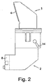
- the position of the rotatable mirror 6 is selected by actuating a lever 14, shown in Figure 2 , which toggles the mirror 6 between the first and second stable positions.
- the lower section 2 further comprises an optical train for directing light from a cassette module 8 comprising an electronic display, such as a VGA display, to the rotatable mirror 6 for reflection to the user.
- the cassette module 8 is removably mounted to the lower section 2 of the periscope for easy replacement. This ensures that the principal electronic components of the periscope can simply be replaced in the event of a malfunction.
- the connection between the cassette module 8 and the lower section 2 of the periscope includes asymmetrically arranged mating formations, such as pegs and sockets, to ensure that the cassette module 8 and hence the display is located in the correct orientation on the lower section 2.
- the VGA display is configured to show electronically generated digital images, such as night vision images, from outside the vehicle in which the periscope is mounted.
- the image from the VGA display is typically black and white and it is therefore important that chromatic aberration by the optical train does not blur the image.
- the VGA display is activated by a microswitch when the lever 14 moves the rotatable mirror 6 to the second stable position and deactivated when the lever 14 moves the rotatable mirror 6 back to the first stable position.
- the optical train comprises a first concave glass lens 9, in this case a plano-concave lens, proximate the VGA display, which is provided to ensure that the image of the VGA display is relatively flat when viewed by the user through the viewing window 7.
- a second plastic aspheric lens 10 is provided after the first lens 9 in the optical train to direct light from the first lens 9 into a glass prism 11.
- the prism 11 reflects the light from the second lens 9 towards the rotatable mirror 6 and also provides a spacing in the optical train which corrects for astigmatism in the image of the VGA display at the viewing window 7.
- the reflected light from the prism 11 passes through a third aspheric plastic lens 12 which is provided with an upper diffractive surface that corrects for chromatic aberration of the image of the VGA display.
- the light from the third lens 12 passes through a fourth glass lens 13, in this case a meniscus lens, which forms the image of the VGA display that is reflected by the rotatable mirror 6 for viewing by the user through the viewing window 7.
- the image of the VGA display is focused at around arm's length for the user.
- the axis of rotation of the rotating mirror 6 is substantially perpendicular to the optical axis of the optical train. It will be seen from Figure 1 that in rotating from the first stable position to the second stable position and back, the rotating mirror 6 always blocks the optical path between the upper section 1 and the lower section 2. In this way, the mirror 6 always prevents light from the VGA display 8 escaping through the transparent window 4. This is important for military operations, particularly at night, where there is a risk that any escaping light could give away the position of the periscope and hence the user.
- the rotating mirror 6 only rotates through approximately 90 degrees between the first stable position and the second stable position. Because the mirror 6 is not required to rotate through a full 360 degrees, the vertical space occupied by the mirror is less than the width of the mirror 6, which allows the periscope to be relatively short in the vertical direction and of minimal depth in the horizontal direction.
- the provision of the prism 11 in the optical train between the VGA display and the rotatable mirror 6 provides an L-shaped optical path. In this way, the extent of the periscope in the vertical direction is reduced compared to a straight optical path. Moreover, the housing of the lower section 2 of the periscope follows the angled reflective surface of the prism 11, which provides additional clearance for the user.
- a periscope comprises an object window 4, a first reflector 5, a second reflector 6, a viewing window 7 and a display port for an electronic display 8.
- the first reflector 5 is arranged to reflect light from the object window 4 towards the second reflector 6.
- the second reflector 6 is selectively movable between a first position of use in which the second reflector 6 reflects light from the first reflector 5 towards the viewing window 7 and a second position of use in which the second reflector 6 reflects light from the display port towards the viewing window 7.
- the periscope provides a simple design that allows the user's view to be switched between an electronically generated image, such as night vision, and a purely optical image.
Landscapes
- Physics & Mathematics (AREA)
- General Physics & Mathematics (AREA)
- Optics & Photonics (AREA)
- Astronomy & Astrophysics (AREA)
- Engineering & Computer Science (AREA)
- General Engineering & Computer Science (AREA)
- Lenses (AREA)
- Instruments For Viewing The Inside Of Hollow Bodies (AREA)
Priority Applications (1)
| Application Number | Priority Date | Filing Date | Title |
|---|---|---|---|
| PL12714040T PL2695014T3 (pl) | 2011-04-08 | 2012-04-04 | Udoskonalony peryskop |
Applications Claiming Priority (2)
| Application Number | Priority Date | Filing Date | Title |
|---|---|---|---|
| GB1105995.3A GB2489741B (en) | 2011-04-08 | 2011-04-08 | Enhanced periscope |
| PCT/GB2012/050763 WO2012137003A1 (en) | 2011-04-08 | 2012-04-04 | Enhanced periscope |
Publications (2)
| Publication Number | Publication Date |
|---|---|
| EP2695014A1 EP2695014A1 (en) | 2014-02-12 |
| EP2695014B1 true EP2695014B1 (en) | 2017-05-17 |
Family
ID=44072188
Family Applications (1)
| Application Number | Title | Priority Date | Filing Date |
|---|---|---|---|
| EP12714040.8A Active EP2695014B1 (en) | 2011-04-08 | 2012-04-04 | Enhanced periscope |
Country Status (8)
| Country | Link |
|---|---|
| US (1) | US9810897B2 (pl) |
| EP (1) | EP2695014B1 (pl) |
| CA (1) | CA2832354A1 (pl) |
| DK (1) | DK2695014T3 (pl) |
| ES (1) | ES2632415T3 (pl) |
| GB (1) | GB2489741B (pl) |
| PL (1) | PL2695014T3 (pl) |
| WO (1) | WO2012137003A1 (pl) |
Families Citing this family (10)
| Publication number | Priority date | Publication date | Assignee | Title |
|---|---|---|---|---|
| GB2519767B (en) * | 2013-10-29 | 2018-05-09 | Kent Periscopes Ltd | Periscope |
| DE102013113223B4 (de) * | 2013-11-29 | 2015-12-03 | GuS Periscopes GmbH & Co. KG | Winkelspiegel |
| ES2734737T3 (es) | 2014-06-12 | 2019-12-11 | Isoclima Spa | Periscopio |
| DE102015102376B4 (de) * | 2015-02-19 | 2018-10-25 | Krauss-Maffei Wegmann Gmbh & Co. Kg | Winkelspiegel mit einem Display zum Einblenden von Zusatzinformationen |
| DE202016102941U1 (de) * | 2016-06-02 | 2016-07-11 | GuS Periscopes GmbH & Co. KG | Winkelspiegel |
| RU169942U1 (ru) * | 2016-06-21 | 2017-04-07 | Федеральное государственное казенное военное образовательное учреждение высшего профессионального образования Рязанское высшее воздушно-десантное ордена Суворова дважды краснознаменное командное училище имени генерала армии В.Ф. Маргелова МО РФ | Прибор ночного видения |
| CN107172336B (zh) * | 2017-06-26 | 2019-01-11 | 维沃移动通信有限公司 | 一种摄像头模组、移动终端及其控制方法 |
| CN108681058A (zh) * | 2018-03-09 | 2018-10-19 | 中国人民解放军陆军装甲兵学院 | 指挥功能型坦克驾驶潜望镜 |
| DE102019131812B4 (de) * | 2019-11-25 | 2021-10-21 | GuS glass + safety GmbH & Co. KG | Winkelspiegel für ein Panzerfahrzeug |
| GB2637189A (en) * | 2024-01-15 | 2025-07-16 | Gooch & Housego Plc | Periscope |
Family Cites Families (13)
| Publication number | Priority date | Publication date | Assignee | Title |
|---|---|---|---|---|
| DE1203491B (de) * | 1963-06-05 | 1965-10-21 | Rodenstock Optik G | Rundblickfernrohr fuer Tag- und Nachtgebrauch |
| US3621131A (en) * | 1969-11-21 | 1971-11-16 | Us Navy | Visual environment simulator |
| US4175825A (en) * | 1978-03-06 | 1979-11-27 | Hughes Aircraft Company | Optical transmission system with a pechan prism for equalizing optical paths |
| JPH0345757Y2 (pl) * | 1985-10-14 | 1991-09-26 | ||
| DE3829708A1 (de) * | 1988-09-01 | 1990-03-15 | Zeiss Carl Fa | Umschaltbarer winkelspiegel fuer periskope |
| FR2662822B1 (fr) * | 1990-06-01 | 1993-05-14 | Thomson Trt Defense | Episcope multi-fonction, a faible encombrement. |
| JPH1164739A (ja) | 1997-08-13 | 1999-03-05 | Fuji Photo Optical Co Ltd | パノラマ観察光学系 |
| FR2803917B1 (fr) * | 2000-01-19 | 2002-12-20 | Giat Ind Sa | Dispositif de vision jour/nuit |
| US6513940B1 (en) * | 2002-02-07 | 2003-02-04 | Chung-Shan Institute Of Science And Technology | Field-of-view switching and focusing system of common-optical-path periscope |
| US6700689B2 (en) * | 2002-04-01 | 2004-03-02 | Su-Min Kung | Adjusting device for adjusting a projecting direction of a view |
| US8264770B2 (en) * | 2007-11-29 | 2012-09-11 | Oasis Advanced Engineering, Inc. | Multi-purpose periscope with display and overlay capabilities |
| DE102008021486B4 (de) * | 2008-04-29 | 2010-06-24 | Krauss-Maffei Wegmann Gmbh & Co. Kg | Klappwinkelspiegel für Kampffahrzeuge |
| DE102008061701A1 (de) * | 2008-12-12 | 2010-06-17 | GuS Präzision in Kunststoff Glas und Optik GmbH & Co. KG | Winkelspiegel für ein Panzerfahrzeug |
-
2011
- 2011-04-08 GB GB1105995.3A patent/GB2489741B/en active Active
-
2012
- 2012-04-04 EP EP12714040.8A patent/EP2695014B1/en active Active
- 2012-04-04 CA CA2832354A patent/CA2832354A1/en not_active Abandoned
- 2012-04-04 WO PCT/GB2012/050763 patent/WO2012137003A1/en not_active Ceased
- 2012-04-04 PL PL12714040T patent/PL2695014T3/pl unknown
- 2012-04-04 US US14/110,235 patent/US9810897B2/en active Active
- 2012-04-04 DK DK12714040.8T patent/DK2695014T3/en active
- 2012-04-04 ES ES12714040.8T patent/ES2632415T3/es active Active
Also Published As
| Publication number | Publication date |
|---|---|
| EP2695014A1 (en) | 2014-02-12 |
| WO2012137003A1 (en) | 2012-10-11 |
| CA2832354A1 (en) | 2012-10-11 |
| GB201105995D0 (en) | 2011-05-18 |
| GB2489741A (en) | 2012-10-10 |
| DK2695014T3 (en) | 2017-07-31 |
| US9810897B2 (en) | 2017-11-07 |
| GB2489741B (en) | 2013-10-02 |
| PL2695014T3 (pl) | 2017-10-31 |
| ES2632415T3 (es) | 2017-09-13 |
| US20140085716A1 (en) | 2014-03-27 |
Similar Documents
| Publication | Publication Date | Title |
|---|---|---|
| EP2695014B1 (en) | Enhanced periscope | |
| JP6311714B2 (ja) | 表示装置 | |
| JP6358248B2 (ja) | 表示装置 | |
| CN112444991B (zh) | 虚像显示装置以及导光装置 | |
| US20180067317A1 (en) | Head mounted display with reduced thickness using a single axis optical system | |
| CN102692707A (zh) | 头部安装型显示装置 | |
| CN104583842A (zh) | 图像显示装置和显示设备 | |
| WO2000079327A1 (en) | Eyeglass display lens system employing off-axis optical design | |
| US9291808B2 (en) | Combination optical aiming device for projectile weapons | |
| JP7702543B2 (ja) | ヘッドアップディスプレイ | |
| JP6830182B2 (ja) | 画像投写装置 | |
| KR20150106022A (ko) | 시도 조절이 가능한 전방 상향 시현용 광학계 | |
| WO2016208196A1 (ja) | ヘッドアップディスプレイおよびヘッドアップディスプレイを搭載した移動体 | |
| WO1994006047A1 (en) | Optical system especially for binoculars and other viewing instruments | |
| JP6064535B2 (ja) | 投射光学系及びそれを備えた画像表示装置 | |
| US20070160367A1 (en) | Optical system | |
| CN110908102B (zh) | 一种摄远倒像物镜的调节机构、倍率镜及瞄具 | |
| WO2001088597A1 (en) | Virtual imaging system for small font text | |
| EP3063583B1 (en) | Periscope | |
| GB2637189A (en) | Periscope | |
| CN112997108A (zh) | 观察光学系统和图像显示装置 | |
| KR102081677B1 (ko) | 시력보정이 가능한 헤드 마운트 디스플레이 장치 | |
| JP2022071922A (ja) | 虚像表示装置及び光学ユニット |
Legal Events
| Date | Code | Title | Description |
|---|---|---|---|
| PUAI | Public reference made under article 153(3) epc to a published international application that has entered the european phase |
Free format text: ORIGINAL CODE: 0009012 |
|
| 17P | Request for examination filed |
Effective date: 20131108 |
|
| AK | Designated contracting states |
Kind code of ref document: A1 Designated state(s): AL AT BE BG CH CY CZ DE DK EE ES FI FR GB GR HR HU IE IS IT LI LT LU LV MC MK MT NL NO PL PT RO RS SE SI SK SM TR |
|
| DAX | Request for extension of the european patent (deleted) | ||
| 17Q | First examination report despatched |
Effective date: 20141022 |
|
| GRAP | Despatch of communication of intention to grant a patent |
Free format text: ORIGINAL CODE: EPIDOSNIGR1 |
|
| INTG | Intention to grant announced |
Effective date: 20160211 |
|
| RBV | Designated contracting states (corrected) |
Designated state(s): AL AT BE BG CH CY CZ DE DK EE ES FI FR GR HR HU IE IS IT LI LT LU LV MC MK MT NL NO PL PT RO RS SE SI SK SM TR |
|
| INTC | Intention to grant announced (deleted) | ||
| GRAP | Despatch of communication of intention to grant a patent |
Free format text: ORIGINAL CODE: EPIDOSNIGR1 |
|
| INTG | Intention to grant announced |
Effective date: 20161206 |
|
| RAP1 | Party data changed (applicant data changed or rights of an application transferred) |
Owner name: KENT PERISCOPES LIMITED |
|
| GRAS | Grant fee paid |
Free format text: ORIGINAL CODE: EPIDOSNIGR3 |
|
| GRAA | (expected) grant |
Free format text: ORIGINAL CODE: 0009210 |
|
| RIN1 | Information on inventor provided before grant (corrected) |
Inventor name: OWEN, GARY |
|
| AK | Designated contracting states |
Kind code of ref document: B1 Designated state(s): AL AT BE BG CH CY CZ DE DK EE ES FI FR GR HR HU IE IS IT LI LT LU LV MC MK MT NL NO PL PT RO RS SE SI SK SM TR |
|
| REG | Reference to a national code |
Ref country code: CH Ref legal event code: EP |
|
| REG | Reference to a national code |
Ref country code: IE Ref legal event code: FG4D |
|
| REG | Reference to a national code |
Ref country code: AT Ref legal event code: REF Ref document number: 894976 Country of ref document: AT Kind code of ref document: T Effective date: 20170615 |
|
| REG | Reference to a national code |
Ref country code: DE Ref legal event code: R096 Ref document number: 602012032528 Country of ref document: DE |
|
| REG | Reference to a national code |
Ref country code: SE Ref legal event code: TRGR |
|
| REG | Reference to a national code |
Ref country code: DK Ref legal event code: T3 Effective date: 20170725 |
|
| REG | Reference to a national code |
Ref country code: ES Ref legal event code: FG2A Ref document number: 2632415 Country of ref document: ES Kind code of ref document: T3 Effective date: 20170913 |
|
| REG | Reference to a national code |
Ref country code: NL Ref legal event code: MP Effective date: 20170517 |
|
| REG | Reference to a national code |
Ref country code: LT Ref legal event code: MG4D |
|
| REG | Reference to a national code |
Ref country code: NO Ref legal event code: T2 Effective date: 20170517 |
|
| PG25 | Lapsed in a contracting state [announced via postgrant information from national office to epo] |
Ref country code: LT Free format text: LAPSE BECAUSE OF FAILURE TO SUBMIT A TRANSLATION OF THE DESCRIPTION OR TO PAY THE FEE WITHIN THE PRESCRIBED TIME-LIMIT Effective date: 20170517 Ref country code: HR Free format text: LAPSE BECAUSE OF FAILURE TO SUBMIT A TRANSLATION OF THE DESCRIPTION OR TO PAY THE FEE WITHIN THE PRESCRIBED TIME-LIMIT Effective date: 20170517 Ref country code: GR Free format text: LAPSE BECAUSE OF FAILURE TO SUBMIT A TRANSLATION OF THE DESCRIPTION OR TO PAY THE FEE WITHIN THE PRESCRIBED TIME-LIMIT Effective date: 20170818 |
|
| PG25 | Lapsed in a contracting state [announced via postgrant information from national office to epo] |
Ref country code: IS Free format text: LAPSE BECAUSE OF FAILURE TO SUBMIT A TRANSLATION OF THE DESCRIPTION OR TO PAY THE FEE WITHIN THE PRESCRIBED TIME-LIMIT Effective date: 20170917 Ref country code: BG Free format text: LAPSE BECAUSE OF FAILURE TO SUBMIT A TRANSLATION OF THE DESCRIPTION OR TO PAY THE FEE WITHIN THE PRESCRIBED TIME-LIMIT Effective date: 20170817 Ref country code: RS Free format text: LAPSE BECAUSE OF FAILURE TO SUBMIT A TRANSLATION OF THE DESCRIPTION OR TO PAY THE FEE WITHIN THE PRESCRIBED TIME-LIMIT Effective date: 20170517 Ref country code: NL Free format text: LAPSE BECAUSE OF FAILURE TO SUBMIT A TRANSLATION OF THE DESCRIPTION OR TO PAY THE FEE WITHIN THE PRESCRIBED TIME-LIMIT Effective date: 20170517 Ref country code: LV Free format text: LAPSE BECAUSE OF FAILURE TO SUBMIT A TRANSLATION OF THE DESCRIPTION OR TO PAY THE FEE WITHIN THE PRESCRIBED TIME-LIMIT Effective date: 20170517 |
|
| PG25 | Lapsed in a contracting state [announced via postgrant information from national office to epo] |
Ref country code: EE Free format text: LAPSE BECAUSE OF FAILURE TO SUBMIT A TRANSLATION OF THE DESCRIPTION OR TO PAY THE FEE WITHIN THE PRESCRIBED TIME-LIMIT Effective date: 20170517 Ref country code: SK Free format text: LAPSE BECAUSE OF FAILURE TO SUBMIT A TRANSLATION OF THE DESCRIPTION OR TO PAY THE FEE WITHIN THE PRESCRIBED TIME-LIMIT Effective date: 20170517 Ref country code: CZ Free format text: LAPSE BECAUSE OF FAILURE TO SUBMIT A TRANSLATION OF THE DESCRIPTION OR TO PAY THE FEE WITHIN THE PRESCRIBED TIME-LIMIT Effective date: 20170517 Ref country code: RO Free format text: LAPSE BECAUSE OF FAILURE TO SUBMIT A TRANSLATION OF THE DESCRIPTION OR TO PAY THE FEE WITHIN THE PRESCRIBED TIME-LIMIT Effective date: 20170517 |
|
| REG | Reference to a national code |
Ref country code: DE Ref legal event code: R097 Ref document number: 602012032528 Country of ref document: DE |
|
| PG25 | Lapsed in a contracting state [announced via postgrant information from national office to epo] |
Ref country code: SM Free format text: LAPSE BECAUSE OF FAILURE TO SUBMIT A TRANSLATION OF THE DESCRIPTION OR TO PAY THE FEE WITHIN THE PRESCRIBED TIME-LIMIT Effective date: 20170517 |
|
| PLBE | No opposition filed within time limit |
Free format text: ORIGINAL CODE: 0009261 |
|
| STAA | Information on the status of an ep patent application or granted ep patent |
Free format text: STATUS: NO OPPOSITION FILED WITHIN TIME LIMIT |
|
| REG | Reference to a national code |
Ref country code: FR Ref legal event code: PLFP Year of fee payment: 7 |
|
| 26N | No opposition filed |
Effective date: 20180220 |
|
| PG25 | Lapsed in a contracting state [announced via postgrant information from national office to epo] |
Ref country code: SI Free format text: LAPSE BECAUSE OF FAILURE TO SUBMIT A TRANSLATION OF THE DESCRIPTION OR TO PAY THE FEE WITHIN THE PRESCRIBED TIME-LIMIT Effective date: 20170517 |
|
| REG | Reference to a national code |
Ref country code: DK Ref legal event code: EBP Effective date: 20180430 Ref country code: NO Ref legal event code: MMEP |
|
| PG25 | Lapsed in a contracting state [announced via postgrant information from national office to epo] |
Ref country code: MC Free format text: LAPSE BECAUSE OF FAILURE TO SUBMIT A TRANSLATION OF THE DESCRIPTION OR TO PAY THE FEE WITHIN THE PRESCRIBED TIME-LIMIT Effective date: 20170517 |
|
| REG | Reference to a national code |
Ref country code: CH Ref legal event code: PL |
|
| REG | Reference to a national code |
Ref country code: SE Ref legal event code: EUG |
|
| REG | Reference to a national code |
Ref country code: BE Ref legal event code: MM Effective date: 20180430 |
|
| REG | Reference to a national code |
Ref country code: IE Ref legal event code: MM4A |
|
| PG25 | Lapsed in a contracting state [announced via postgrant information from national office to epo] |
Ref country code: LU Free format text: LAPSE BECAUSE OF NON-PAYMENT OF DUE FEES Effective date: 20180404 Ref country code: FI Free format text: LAPSE BECAUSE OF NON-PAYMENT OF DUE FEES Effective date: 20180404 Ref country code: NO Free format text: LAPSE BECAUSE OF NON-PAYMENT OF DUE FEES Effective date: 20180430 Ref country code: SE Free format text: LAPSE BECAUSE OF NON-PAYMENT OF DUE FEES Effective date: 20180405 |
|
| PG25 | Lapsed in a contracting state [announced via postgrant information from national office to epo] |
Ref country code: LI Free format text: LAPSE BECAUSE OF NON-PAYMENT OF DUE FEES Effective date: 20180430 Ref country code: CH Free format text: LAPSE BECAUSE OF NON-PAYMENT OF DUE FEES Effective date: 20180430 Ref country code: BE Free format text: LAPSE BECAUSE OF NON-PAYMENT OF DUE FEES Effective date: 20180430 |
|
| PG25 | Lapsed in a contracting state [announced via postgrant information from national office to epo] |
Ref country code: IT Free format text: LAPSE BECAUSE OF NON-PAYMENT OF DUE FEES Effective date: 20180404 Ref country code: IE Free format text: LAPSE BECAUSE OF NON-PAYMENT OF DUE FEES Effective date: 20180404 |
|
| PG25 | Lapsed in a contracting state [announced via postgrant information from national office to epo] |
Ref country code: DK Free format text: LAPSE BECAUSE OF NON-PAYMENT OF DUE FEES Effective date: 20180430 |
|
| REG | Reference to a national code |
Ref country code: AT Ref legal event code: MM01 Ref document number: 894976 Country of ref document: AT Kind code of ref document: T Effective date: 20180404 |
|
| REG | Reference to a national code |
Ref country code: ES Ref legal event code: FD2A Effective date: 20190911 |
|
| PG25 | Lapsed in a contracting state [announced via postgrant information from national office to epo] |
Ref country code: AT Free format text: LAPSE BECAUSE OF NON-PAYMENT OF DUE FEES Effective date: 20180404 Ref country code: ES Free format text: LAPSE BECAUSE OF NON-PAYMENT OF DUE FEES Effective date: 20180405 |
|
| PG25 | Lapsed in a contracting state [announced via postgrant information from national office to epo] |
Ref country code: MT Free format text: LAPSE BECAUSE OF NON-PAYMENT OF DUE FEES Effective date: 20180404 |
|
| REG | Reference to a national code |
Ref country code: AT Ref legal event code: UEP Ref document number: 894976 Country of ref document: AT Kind code of ref document: T Effective date: 20170517 |
|
| PG25 | Lapsed in a contracting state [announced via postgrant information from national office to epo] |
Ref country code: PL Free format text: LAPSE BECAUSE OF NON-PAYMENT OF DUE FEES Effective date: 20180404 |
|
| PG25 | Lapsed in a contracting state [announced via postgrant information from national office to epo] |
Ref country code: PT Free format text: LAPSE BECAUSE OF FAILURE TO SUBMIT A TRANSLATION OF THE DESCRIPTION OR TO PAY THE FEE WITHIN THE PRESCRIBED TIME-LIMIT Effective date: 20170517 Ref country code: HU Free format text: LAPSE BECAUSE OF FAILURE TO SUBMIT A TRANSLATION OF THE DESCRIPTION OR TO PAY THE FEE WITHIN THE PRESCRIBED TIME-LIMIT; INVALID AB INITIO Effective date: 20120404 |
|
| PG25 | Lapsed in a contracting state [announced via postgrant information from national office to epo] |
Ref country code: CY Free format text: LAPSE BECAUSE OF FAILURE TO SUBMIT A TRANSLATION OF THE DESCRIPTION OR TO PAY THE FEE WITHIN THE PRESCRIBED TIME-LIMIT Effective date: 20170517 Ref country code: MK Free format text: LAPSE BECAUSE OF NON-PAYMENT OF DUE FEES Effective date: 20170517 |
|
| PG25 | Lapsed in a contracting state [announced via postgrant information from national office to epo] |
Ref country code: AL Free format text: LAPSE BECAUSE OF FAILURE TO SUBMIT A TRANSLATION OF THE DESCRIPTION OR TO PAY THE FEE WITHIN THE PRESCRIBED TIME-LIMIT Effective date: 20170517 |
|
| PG25 | Lapsed in a contracting state [announced via postgrant information from national office to epo] |
Ref country code: TR Free format text: LAPSE BECAUSE OF NON-PAYMENT OF DUE FEES Effective date: 20180404 |
|
| PGFP | Annual fee paid to national office [announced via postgrant information from national office to epo] |
Ref country code: DE Payment date: 20250410 Year of fee payment: 14 |
|
| PGFP | Annual fee paid to national office [announced via postgrant information from national office to epo] |
Ref country code: FR Payment date: 20250410 Year of fee payment: 14 |