EP2693295A2 - Hinge device and electronic apparatus using that hinge device - Google Patents
Hinge device and electronic apparatus using that hinge device Download PDFInfo
- Publication number
- EP2693295A2 EP2693295A2 EP13174285.0A EP13174285A EP2693295A2 EP 2693295 A2 EP2693295 A2 EP 2693295A2 EP 13174285 A EP13174285 A EP 13174285A EP 2693295 A2 EP2693295 A2 EP 2693295A2
- Authority
- EP
- European Patent Office
- Prior art keywords
- hinge
- housing
- cover
- pivot
- hinge device
- Prior art date
- Legal status (The legal status is an assumption and is not a legal conclusion. Google has not performed a legal analysis and makes no representation as to the accuracy of the status listed.)
- Granted
Links
Images




Classifications
-
- G—PHYSICS
- G06—COMPUTING OR CALCULATING; COUNTING
- G06F—ELECTRIC DIGITAL DATA PROCESSING
- G06F1/00—Details not covered by groups G06F3/00 - G06F13/00 and G06F21/00
- G06F1/16—Constructional details or arrangements
- G06F1/1613—Constructional details or arrangements for portable computers
- G06F1/1633—Constructional details or arrangements of portable computers not specific to the type of enclosures covered by groups G06F1/1615 - G06F1/1626
- G06F1/1675—Miscellaneous details related to the relative movement between the different enclosures or enclosure parts
- G06F1/1681—Details related solely to hinges
-
- G—PHYSICS
- G06—COMPUTING OR CALCULATING; COUNTING
- G06F—ELECTRIC DIGITAL DATA PROCESSING
- G06F1/00—Details not covered by groups G06F3/00 - G06F13/00 and G06F21/00
- G06F1/16—Constructional details or arrangements
Definitions
- the present application relates to a hinge device which is used for opening and closing a housing of a display part with respect a housing of a keyboard part and to an electronic apparatus which uses the hinge device.
- the housing of the display part is connected to the housing of the keyboard part to be able to open and close by a hinge device.
- the hinge device is provided at a part forming the axis of opening/closing of the two housings (see Japanese Laid-Open Patent Publication No. 2011-58607 and Japanese Laid-Open Patent Publication No. 2008-250635 ). Further, when the electronic apparatus is not being used, the hinge device is used to close the display part and lay it flat over the keyboard part thereby enabling the electronic apparatus to be made more compact.
- a hinge device in general is provided with a bracket which is attached to one housing and a pivot which is attached to the other housing and is designed so that the bracket holds the pivot in a rotatable manner.
- the pivot can be made to turn with respect to the bracket so as to open or close the display part with respect to the keyboard part.
- This hinge device is a part which stands out in the appearance of an electronic apparatus, so a hinge cover is used to cover the hinge device and maintain a beautiful design and to prevent injury due to mistaken insertion of a finger into the hinge device.
- Various ideas are used to improve the method of installation of the cover for covering the hinge device.
- the hinge cover which conceals the pivot of the hinge device is provided at the far side of the housing of the keyboard part. Further, if adopting a structure in which the hinge cover is screwed to the housing of the keyboard part, the hinge cover will come off if the screws are removed. In such a structure, when performing maintenance on the display part, the screws are removed in the state with the display part closed, the display part is opened as it is, and the front cover of the display part is removed. When the display part finishes being maintained, the display part is attached to the keyboard part by assembly by the reverse procedure.
- the hinge cover may be considered to fasten the hinge cover to the housing of the keyboard part of the electronic apparatus by a tab member which is provided at the hinge cover.
- a tab member which is provided at the hinge cover.
- the hinge cover will easily detach from the keyboard part when disassembling the front cover of the display part.
- the structure of the hinge cover will end up becoming complicated.
- the present application has as its object to provide a hinge device which connects a keyboard part and a display part of an electronic apparatus, wherein a hinge cover will not be mistakenly detached at the time of use by a user and the hinge cover can be simply detached when detaching the front cover of the display part at the time of maintenance of the display part, and to provide an electronic apparatus which uses the hinge device.
- the present application provides a hinge device which is provided between a first housing and a second housing which is provided with a front cover of a display and which connects the second housing to the first housing to be able to open and close, wherein the hinge device is provided with a bracket which is provided with a first mounting part and a rotatable holding part of a pivot, the first mounting part being fastened to an end part of one of the housings, a hinge pivot member which is provided with a second mounting part and a pivot, the second mounting part being fastened to an end part of the other of the housings, the pivot being held by the rotatable holding part, and a hinge cover which is attached to the pivot of the hinge pivot member to be able to slide in its axial direction and which covers the pivot and the rotatable holding part of the bracket in a state where the pivot is held at the rotatable holding part, the hinge cover has an engagement tab which engages with the second housing to prevent the hinge cover from detaching from the pivot by the cover being slid
- the present application provides an electronic apparatus which uses a hinge device which is provided between a first housing and a second housing provided with a front cover of a display and which connects the second housing to the first housing to be able to be opened and closed.
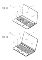
- FIG. 1A is a perspective view which illustrates the appearance of an electronic apparatus which is provided with a keyboard part and a display part which are connected by a hinge device of the present application.
- FIG. 1B is a perspective view which illustrates the appearance of an electronic apparatus which is provided with a conventional hinge device of the present application.
- FIG. 2A is a perspective view which illustrates one example of a hinge unit which forms a hinge device of the present application.
- FIG. 2B is a disassembled perspective view which illustrates an embodiment where the hinge unit which is illustrated in FIG. 2A is used to connect the display part and the keyboard part.
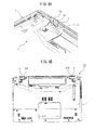
- FIG. 3A is a perspective view of the electronic apparatus of FIG. 1A which is provided with the hinge device which is illustrated in FIG. 2A as seen from the bottom surface side.
- FIG. 3B is an assembled perspective view of the partially enlarged view of part A of FIG. 3A plus a hinge cover which is used for the hinge device of the present application.
- FIG. 4A is a partially enlarged perspective view which illustrates the same portion as FIG. 3B which illustrates the state of attachment of the hinge cover which is illustrated in FIG. 3B attached to the hinge device of the electronic apparatus.
- FIG. 4B is a bottom surface view of an electronic apparatus in a state where hinge covers are attached to hinge devices as seen from the bottom surface.
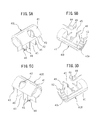
- FIG. 5A is a perspective view of a hinge cover which is used at the left side of the back surface of the electronic apparatus which is illustrated in FIG. 4B as seen from the front surface.
- FIG. 5B is a perspective view of the hinge cover which is illustrated in FIG. 5A as seen from the back surface.
- FIG. 5C is a perspective view of a hinge cover which is used at the right side of the back surface of the electronic apparatus which is illustrated in FIG. 4B as seen from the front surface.
- FIG. 5D is a perspective view of the hinge cover which is illustrated in FIG. 5C as seen from the back surface.
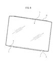
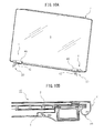
- FIG. 6 is a perspective view which illustrates the structure of one embodiment of a front cover which is used for the hinge device of the present application of the electronic apparatus which is illustrated in FIG. 1A .
- FIG. 7A is a partially enlarged perspective view which illustrates a state of a stage before a hinge cover is attached to a hinge device which is attached to a display part of the electronic apparatus which is illustrated in FIG. 1A .
- FIG. 7B is a partially enlarged perspective view which illustrates a state where the hinge cover which is illustrated in FIG. 17A is attached to the hinge device.
- FIG. 7C is a schematic cross-sectional view which illustrates the connected state of the hinge cover and the housing of the display part along the line B-B of FIG. 7B .
- FIG. 8A is a partially enlarged perspective view which illustrates the state where the hinge cover is made to slide along the pivot of the hinge device from the state of FIG. 7B so as to engage with the housing of the display part.
- FIG. 8B is a schematic cross-sectional view which illustrates the connected state of the hinge cover and the housing of the display part along the line C-C of FIG. 8A .
- FIG. 8C is a partially enlarged assembled perspective view which illustrates the process of attaching the front cover to the display part which is illustrated in FIG. 8B .
- FIG. 9A is a partially enlarged perspective view which illustrates the state of attaching the front cover which is illustrated in FIG. 8C to the display part.
- FIG. 9B is a schematic cross-sectional view which illustrates the connected state of the hinge cover and the housing of the display part along the line D-D of FIG. 9A .
- FIG. 9C is a partially enlarged perspective view which illustrates the state of fastening a screw in a through hole of a projecting piece which projects from the front cover which is illustrated in FIG. 9A and FIG. 9B .
- FIG. 9D is a schematic cross-sectional view which illustrates the connected state of the hinge cover and the housing of the display part along the line E-E of FIG. 9C .
- FIG. 10A is a perspective view which illustrates the appearance of the display part alone of the present application to which hinge devices and the front cover are attached.
- FIG. 10B is a partial cross-sectional view which illustrates the position of a hinge cover in an electronic apparatus which is provided with the hinge devices of the present application which are illustrated in FIGS. 4A and 4B .
- FIG. 1A is a perspective view which illustrates the appearance of an electronic apparatus 10 which is provided with a hinge device 4 of the present application.
- the electronic apparatus 10 has a keyboard part 1 which is provided with input keys 5 and a display part 2 which is provided with a display.
- the display part 2 has a front cover 3 which protects the display attached to it.
- the display part 2 can be folded over the keyboard part 1 by the hinge device 4.
- the hinge device 4 which is provided in the electronic apparatus 10 which is covered by the present application is at a position which is hidden from the user of the electronic apparatus 10 when opening and closing the display part 2 with respect to the keyboard part 1.
- FIG. 1B is a perspective view which illustrates the appearance of an electronic apparatus 50 which is provided with a conventional hinge device 54.
- the electronic apparatus 50 has a keyboard part 51 which is provided with input keys 55 and a display part 52 which is provided with a display.
- the display part 52 has a front cover 53 which protects the display attached to it.
- the display part 52 can be folded over the keyboard part 51 by the hinge device 54.
- the hinge device 54 which is provided at the electronic apparatus 50, the pivot of the hinge device 54 is at the upper side of the keyboard part 51, so the hinge device 54 is provided to be visible to the user of the electronic apparatus 50.
- FIG. 2A is a perspective view which illustrates one example of a hinge unit 4U which is used as the hinge device 4 which is used in the electronic apparatus 10.
- the hinge unit 4U of this embodiment is provided with a bracket 20 which rotatably holds a pivot 33 and with a hinge pivot member 30 to which the pivot 33 is fastened.
- the bracket 20 is attached to the display part 2, while the hinge pivot member 30 is attached to the keyboard part 1.
- the bracket 20 has two mounting parts 21 and 22 which are provided with mounting surfaces parallel to the pivot 33 and has rotatable holding parts 23 and 24 which are provided projecting from the mounting parts 21 and 22 and rotatably hold the pivot 33.
- the hinge pivot member 30 has a pivot mounting part 36 which fastens the pivot 33.
- This pivot mounting part 36 is provided at a front end part of an arm part 31 in a direction perpendicular to the arm part 31.
- a base part of the arm part 31 is bent at right angles to the arm part 31 to form the mounting part 32 to the display part 2.
- the mounting part 32 is provided with three through holes 34 for passing screws in this embodiment.
- the hinge unit 4U which is illustrated in FIG. 2A , as illustrated in FIG. 2B , is attached to the display part 2 by the two mounting parts 21 and 22.
- the bottom surface 11B of the housing 11 of the keyboard part 1 of the electronic apparatus 10 is provided with a boss part 13 for attachment of the hinge pivot member 30.
- the top surface of the boss part 13 is provided with_screw holes 14 to which screws may be fastened.
- the number of screw holes 14 is matched with the number of through holes 24 at the mounting part 32 of the bracket 20.
- the arm part 31 of the bracket 20 is attached to the boss part 13 along the side surface of the boss part 13.
- the mounting part 32 of the hinge pivot member 30 can be fastened to the boss part 13 by screwing a screw 6 which is passed through a through hole 34 to a screw hole 14 of the boss part 13.
- FIG. 3A is a perspective view of the electronic apparatus 10 which is illustrated in FIG. 1A which is provided with the hinge device 4 which was explained in FIGS. 2A and 2B as seen from the bottom surface, while FIG. 3B is an assembled perspective view including the partially enlarged view of part A of FIG. 3A plus a hinge cover 40 which is used for the hinge device 4 of the present application.
- the single electronic apparatus 10 is provided with hinge devices 4 at two locations.
- the hinge devices 4 are provided at the back side of the keyboard part 1 at a lower side position of the display part 2. Therefore, as illustrated in FIG. 1A , in the electronic apparatus 10 to which the present application is applied, the hinge devices 4 are not visible to the party operating the electronic apparatus 10.
- hinge devices 4 which are provided with the brackets 20 and hinge pivot members 30 which are explained in FIGS. 2A and 2B are at positions which are not visible to the operator of the electronic apparatus 10.
- the rotatable holding parts 22 of the brackets 20 and the pivots 33 of the hinge pivot members 30 of the hinge devices 4 are exposed at slots 15 of the housing 11. Therefore, in the hinge devices 4 of the present application, as illustrated in FIG. 3B , hinge covers 40 are attached to the slots 15 to cover the rotatable holding parts 22 of the brackets 20 and the pivots 33 of the hinge pivot members 30 and prevent the user from mistakenly touching the rotatable holding parts 22 and pivots 33.
- the configuration of the hinge covers 40 will be explained in detail later, but each hinge cover 40 has a blind plate 41, a circular hole 42, a pivot mounting plate 43, an engagement tab 44, a space 45, and mounting plates 46.
- FIG. 4A is a partially enlarged perspective view which illustrates the state of attachment of a hinge cover 40 which is illustrated in FIG. 3B attached to a slot 15 of the housing 11 of the keyboard part 1 to conceal the hinge device 4.
- the hinge cover 40 does not slide inside the slot 15.
- the electronic apparatus 10 is provided with hinge devices 4 at two locations, so two hinge covers 40 which cover the hinge devices 4 are required.
- FIG. 4B is a bottom surface view of an electronic apparatus 10 which illustrates a state where hinge covers 40 are attached to the hinge devices 4 at two locations of the back surface of the electronic apparatus 10.
- the hinge covers 40 which are attached to two locations of the back surface of the electronic apparatus 10 are not the same but are symmetrical in shape to the left and right at the back surface of the electronic apparatus 10.
- the hinge cover 40 at the left side of the back surface of the electronic apparatus 10 is referred to as the "hinge cover 40L”
- the hinge cover 40 at the right side is referred to as the "hinge cover 40R”.
- the hinge covers 40L and 40R are attached by screws 6 to the back surface of the electronic apparatus 10.
- FIG. 5A is a perspective view of the hinge cover 40L which is used at the left side of the back surface of the electronic apparatus 10 which is illustrated in FIG. 4B as seen from the front surface
- FIG. 5B is a perspective view of the hinge cover 40L which is illustrated in FIG. 5A as seen from the back surface
- FIG. 5C is a perspective view of the hinge cover 40R which is used at the right side of the back surface of the electronic apparatus 10 which is illustrated in FIG. 4B as seen from the front surface
- FIG. 5D is a perspective view of the hinge cover 40R which is illustrated in FIG. 5C as seen from the back surface.
- the hinge covers 40L and 40R are just symmetric in shape to the left and right. They are configured exactly the same. Here, the hinge covers will be assigned the representative numbers "40" to explain their structures.
- Each hinge cover 40 is provided with the blind p1_ate 41, the circular hole 42 which is provided at the blind plate 41, the pivot mounting plate 43, and the plurality of mounting plates 46.
- the blind plate 41 is curved and covers the rotatable holding part 22, pivot 33, and slot 15 which are illustrated in FIG. 3B .
- the pivot mounting plate 43 is attached to the pivot 33, while the plurality of mounting plates 46 are inserted into the slot 15.
- the pivot mounting plate 43 has a recessed part 43a into which the pivot 33 is inserted, while the mounting plates 46 are shaped similar to the cross-sectional shape of the slot 15 in the direction vertical to the longitudinal direction.
- an engagement tab 44 is provided for engaging the hinge cover 40 with part of the housing 12 of the display part 2 to prevent it from detaching from the housing 12 of the display part 2.
- the two mounting plates 46 at the center part of the hinge cover 40 are arranged at the two sides of the circular hole 42 at the blind plate 41. Between these two mounting plates 46, a space 45 of a predetermined distance is provided.
- Each hinge cover 40 is made of plastic and has a total length shorter than the length of the slot 15 in the longitudinal direction by exactly a length of at least the height of the engagement tab 44 from the mounting plates 46.
- FIG. 6 is a perspective view of the electronic apparatus 10 which is illustrated in FIG. 1A which illustrates extracted just the front cover 3 which protects the display at the display part 2.
- the front cover 3 is provided with a transparent acrylic sheet or glass sheet at the inside of a frame 3f.
- projecting pieces 7 are provided at two locations.
- the projecting pieces 7 are provided with through holes 8 which pass screws for attaching the front cover 3 to the display part 2.
- the widths of the projecting pieces 7 are widths which enable insertion with substantially no clearance into the space 45 at the hinge covers 40 explained in FIG. 5A to 5D .
- FIGS. 1A and 1B to FIG. 6 were used to explain the configuration of the hinge device 4 of the electronic apparatus 10 and configuration of the hinge cover 40 which covers the hinge device 4 and, furthermore, the configuration of the front cover 3 which is attached to the display part 2 of the electronic apparatus 10.
- FIGS. 7A to 7C to FIGS. 10A and 10B will be used to explain the process of attaching the hinge cover 40 to a hinge device 4 which is already attached to the display part 2 and attaching the front cover 3 to the display part 2 so as to prevent the hinge cover 40 from detaching from the display part 2.
- FIG. 7A is a partially enlarged perspective view which illustrates the state of the stage before attaching a hinge cover 40 to a hinge device 4 which is attached to the display part 2 of the electronic apparatus 10 which is illustrated in FIG. 1A .
- the bracket 20 is already attached to the display part 2.
- the pivot 33 of the hinge pivot member 30 is rotatably held by the rotatable holding parts 23 and 24 of the bracket 20.
- this state is the state where the hinge pivot member 30 is detached from the keyboard part of the electronic apparatus.
- the configuration of the hinge pivot member 30 has already been explained, so here only reference numerals will be attached to the members forming the hinge pivot member 30 and explanations will be omitted.
- reference numeral 9 which is illustrated in FIG. 7A is a screw hole which is provided at the housing 12 of the display part.
- FIG. 7B is a partially enlarged perspective view which illustrates the state where the hinge cover 40 which is illustrated in FIG. 7A is attached to the hinge device 4, while FIG. 7C is a schematic cross-sectional view which illustrates the connected state of the hinge cover 40 and the housing 12 of the display part along the line B-B of FIG. 7B .
- FIG. 7C illustrates only the positional relationship of the hinge cover 40 and the housing 12 of the display part. Illustration of the pivot 33 of the hinge device 4 is omitted.
- the hinge cover 40 is attached to the pivot 33 by the pivot mounting plate 43 which was explained in FIG. 5A to FIG. 5D . In this state, the screw hole 9 and the circular hole 32 of the hinge cover 40 are not centered with each other and the engagement tab 44 of the hinge cover 40 is not inserted in the engagement hole 12H at the housing 12 of the display part.
- FIG. 8A is a partially enlarged perspective view which illustrates the state of sliding the hinge cover 40 from the state of FIG. 7B along the pivot 33 of the hinge device 4 in the direction illustrated by the white arrow L to engage with the housing 12 of the display part.
- FIG. 8B is a schematic cross-sectional view which illustrates the connected state of the hinge cover 40 and the housing 12 of the display part along the line C-C of FIG. 8A.
- FIG. 8B also illustrates only the positional relationship between the hinge cover 40 and the housing 12 of the display part. Illustration of the pivot 33 of the hinge device 4 is omitted.
- FIG. 8C is a partially enlarged assembled perspective view which illustrates the process of attachment of the front cover 3 to the display part 2 which is illustrated in FIG. 8B .
- the position of a projecting piece 7 which is provided at the frame of the front cover 3 matches the position of the space 45 at the hinge cover 40 after sliding which is illustrated in FIG. 8A . Therefore, if attaching the front cover 3 to the display part 2, the projecting piece 7 is inserted into the space 45 of the hinge cover 40.
- FIG. 9A is a partially enlarged perspective view which illustrates the state where the front cover 3 which is illustrated in FIG. 8C is attached to the display part 2
- FIG. 9B is a schematic cross-sectional view which illustrates the connected state of the hinge cover 40 and the housing 12 of the display part along the line D-D of FIG. 9A .
- the width of a projecting piece 7 is a width enabling insertion with substantially no clearance into the space 45 at the hinge cover 40. Further, if the projecting piece 7 is inserted into the space 45, as illustrated in FIG. 9B , the projecting piece 7 enters the space 45 with no clearance and the through hole 8 which is provided at the projecting piece 7 is aligned with the screw hole 9 which is provided at the housing 12 of the display part.
- FIG. 9C is a partially enlarged perspective view which illustrates the state where a screw 6 is passed through the through hole 8 of a projecting piece 7 which is provided at the front cover 3 which is illustrated in FIGS. 9A and 9B and screwed to a screw hole 9 which is provided at the housing 12 of the display part.
- FIG. 9D is a schematic cross-sectional view which illustrates the connected state of a hinge cover 40 and the housing 12 of the display part along the line E-E of FIG. 9C .
- the screw 6 may be engaged with the through hole 8 of the projecting piece 7 through the circular hole 42 of the hinge cover 40 and screwed with the screw hole 9 through the circular hole 42 by a screwdriver.
- the screw 6 is used to prevent the front cover 3 from detaching from the housing 12 of the display part.
- the hinge cover 40 does not move since the projecting piece 7 enters the space 45 with no clearance. Accordingly, the hinge cover 40 is held in a state connected to the housing 12 of the display part and will not detach from the housing 12 of the display part.
- FIG. 10A is a perspective view which illustrates the appearance of the display part 2, standing alone, which illustrates the state of the display part 2 to which the hinge devices 4 have been attached through the process of FIGS. 7A to 7C to FIGS. 9A to 9C to which, further, the hinge covers 40 and front cover 3 are attached.
- FIG. 10B is a partial cross-sectional view which illustrates the position of a hinge cover 40 in the electronic apparatus 10 which is provided with the hinge devices 4 which are illustrated in FIGS. 4A and 4B . In this way, the display part 2 in the state with the hinge covers 40 being used to cover the hinge devices 4 can be detached from the keyboard part of the electronic apparatus.
- the hinge covers 40 are fit in the slots 15 which were explained in FIGS. 3A and 3B . Further, at the time of inspection of the display part 2, if detaching the display part 2 from the keyboard part and inserting a screwdriver into the circular holes 42 to remove the screws, the front cover 3 can be detached.
- the hinge device With the structure of the hinge device explained above, it is possible to remove the keyboard cover by just detaching the screws in the hinge covers.
- the hinge covers are easy to attach to and detach from the hinge devices and will not detach at the time of use by the user. Further, using such hinge devices, it is possible to realize an electronic apparatus which is provided with pivot structures which are easy to disassemble and assemble at minimal cost.
- the projecting pieces 7 which are formed at the frame 3f of the front cover 3 are provided with through holes 8, and the front cover 3 is screwed to the screw holes 9 which are provided at the housing 12 of the display part by screws 6 which are inserted into the through holes.
- the front cover 3 can be attached to the housing 12 of the display part at other locations and the projecting pieces 7 which are formed at the frame 3f of the front cover 3 can be given only the function of restricting movement of the hinge covers and the through holes 8 omitted.
- the front cover 3 may be provided with mounting pieces which are provided with mounting holes in addition to the projecting pieces 7 and screws which are passed through the mounting pieces may be used to screw them to the screw holes which are provided in the housing 12 of the display part 2.
- the brackets can be attached to the keyboard part side and the hinge pivot members can be attached to the display part side.
Landscapes
- Engineering & Computer Science (AREA)
- Theoretical Computer Science (AREA)
- Computer Hardware Design (AREA)
- Human Computer Interaction (AREA)
- Physics & Mathematics (AREA)
- General Engineering & Computer Science (AREA)
- General Physics & Mathematics (AREA)
- Pivots And Pivotal Connections (AREA)
- Casings For Electric Apparatus (AREA)
- Telephone Set Structure (AREA)
- Calculators And Similar Devices (AREA)
Abstract

Description
- This application claims priority from, and incorporates by reference the entire disclosure of, Japanese Patent Application No.
2012-169585, filed on July 31, 2012 - The present application relates to a hinge device which is used for opening and closing a housing of a display part with respect a housing of a keyboard part and to an electronic apparatus which uses the hinge device.
- In a notebook PC or other such electronic apparatus which is provided with a keyboard part and a display part, the housing of the display part is connected to the housing of the keyboard part to be able to open and close by a hinge device. The hinge device is provided at a part forming the axis of opening/closing of the two housings (see Japanese Laid-Open Patent Publication No.
2011-58607 2008-250635 - A hinge device in general is provided with a bracket which is attached to one housing and a pivot which is attached to the other housing and is designed so that the bracket holds the pivot in a rotatable manner. In an electronic apparatus which is provided with a keyboard part and a display part, the pivot can be made to turn with respect to the bracket so as to open or close the display part with respect to the keyboard part. This hinge device is a part which stands out in the appearance of an electronic apparatus, so a hinge cover is used to cover the hinge device and maintain a beautiful design and to prevent injury due to mistaken insertion of a finger into the hinge device. Various ideas are used to improve the method of installation of the cover for covering the hinge device.
- Among these, there is the technique of arranging the pivot itself of the hinge device at the outside of a side surface of the far side of the housing of the keyboard part of the electronic apparatus to conceal the hinge device from the side which opens and closes the display part and thereby make the hinge device invisible to the user. In this regard, even if employing this technique, the hinge device is exposed at the outside of the side surface at the far side of the housing of the keyboard part of the electronic apparatus. For this reason, when the user puts his hand at the back side of the keyboard part of the electronic apparatus, he might mistakenly insert a finger in the hinge device. To prevent this, a hinge cover which covers the hinge device is necessary. On the other hand, in a structure which conceals the hinge device at the far side of the housing of the keyboard part of the electronic apparatus, the structure for connecting the display part to the hinge device becomes complicated and the hinge cover member also becomes complex.
- In an electronic apparatus which employs a structure which conceals the hinge device from the side which opens and closes the display part, the hinge cover which conceals the pivot of the hinge device is provided at the far side of the housing of the keyboard part. Further, if adopting a structure in which the hinge cover is screwed to the housing of the keyboard part, the hinge cover will come off if the screws are removed. In such a structure, when performing maintenance on the display part, the screws are removed in the state with the display part closed, the display part is opened as it is, and the front cover of the display part is removed. When the display part finishes being maintained, the display part is attached to the keyboard part by assembly by the reverse procedure.
- In this regard, when fastening a hinge cover by screws to the housing of the keyboard part of an electronic apparatus, the hinge cover is liable to fall off when opening and closing the apparatus. For this reason, even if possible to remove the hinge cover to detach the front cover of the display part, attaching the front cover to the display part and connecting the display part to the keyboard part become extremely difficult in terms of assembly process.
- Therefore, it may be considered to fasten the hinge cover to the housing of the keyboard part of the electronic apparatus by a tab member which is provided at the hinge cover. However, when fastening a hinge cover by a tab member to a housing of a keyboard part of an electronic apparatus, there is the issue that the hinge cover will easily detach from the keyboard part when disassembling the front cover of the display part. Further, if fabricating the hinge cover so that the hinge cover does not mistakenly detach from the keyboard part during use of the electronic apparatus by the user, the structure of the hinge cover will end up becoming complicated.
- In one aspect, the present application has as its object to provide a hinge device which connects a keyboard part and a display part of an electronic apparatus, wherein a hinge cover will not be mistakenly detached at the time of use by a user and the hinge cover can be simply detached when detaching the front cover of the display part at the time of maintenance of the display part, and to provide an electronic apparatus which uses the hinge device.
- According to one aspect, the present application provides a hinge device which is provided between a first housing and a second housing which is provided with a front cover of a display and which connects the second housing to the first housing to be able to open and close, wherein the hinge device is provided with a bracket which is provided with a first mounting part and a rotatable holding part of a pivot, the first mounting part being fastened to an end part of one of the housings, a hinge pivot member which is provided with a second mounting part and a pivot, the second mounting part being fastened to an end part of the other of the housings, the pivot being held by the rotatable holding part, and a hinge cover which is attached to the pivot of the hinge pivot member to be able to slide in its axial direction and which covers the pivot and the rotatable holding part of the bracket in a state where the pivot is held at the rotatable holding part, the hinge cover has an engagement tab which engages with the second housing to prevent the hinge cover from detaching from the pivot by the cover being slid after being attached to the pivot and a space part which opens in the direction of the second housing in the engaged state of the engagement tab, the front cover is provided with a projecting piece which is inserted into the space part if attached to the second housing when the engagement tab of the hinge cover is engaged, and the hinge cover is blocked from movement in the axial direction by the projecting piece in the state where the front cover is attached.
- According to another aspect, the present application provides an electronic apparatus which uses a hinge device which is provided between a first housing and a second housing provided with a front cover of a display and which connects the second housing to the first housing to be able to be opened and closed.
-
FIG. 1A is a perspective view which illustrates the appearance of an electronic apparatus which is provided with a keyboard part and a display part which are connected by a hinge device of the present application. -
FIG. 1B is a perspective view which illustrates the appearance of an electronic apparatus which is provided with a conventional hinge device of the present application. -
FIG. 2A is a perspective view which illustrates one example of a hinge unit which forms a hinge device of the present application. -
FIG. 2B is a disassembled perspective view which illustrates an embodiment where the hinge unit which is illustrated inFIG. 2A is used to connect the display part and the keyboard part. -
FIG. 3A is a perspective view of the electronic apparatus ofFIG. 1A which is provided with the hinge device which is illustrated inFIG. 2A as seen from the bottom surface side. -
FIG. 3B is an assembled perspective view of the partially enlarged view of part A ofFIG. 3A plus a hinge cover which is used for the hinge device of the present application. -
FIG. 4A is a partially enlarged perspective view which illustrates the same portion asFIG. 3B which illustrates the state of attachment of the hinge cover which is illustrated inFIG. 3B attached to the hinge device of the electronic apparatus. -
FIG. 4B is a bottom surface view of an electronic apparatus in a state where hinge covers are attached to hinge devices as seen from the bottom surface. -
FIG. 5A is a perspective view of a hinge cover which is used at the left side of the back surface of the electronic apparatus which is illustrated inFIG. 4B as seen from the front surface. -
FIG. 5B is a perspective view of the hinge cover which is illustrated inFIG. 5A as seen from the back surface. -
FIG. 5C is a perspective view of a hinge cover which is used at the right side of the back surface of the electronic apparatus which is illustrated inFIG. 4B as seen from the front surface. -
FIG. 5D is a perspective view of the hinge cover which is illustrated inFIG. 5C as seen from the back surface. -
FIG. 6 is a perspective view which illustrates the structure of one embodiment of a front cover which is used for the hinge device of the present application of the electronic apparatus which is illustrated inFIG. 1A . -
FIG. 7A is a partially enlarged perspective view which illustrates a state of a stage before a hinge cover is attached to a hinge device which is attached to a display part of the electronic apparatus which is illustrated inFIG. 1A . -
FIG. 7B is a partially enlarged perspective view which illustrates a state where the hinge cover which is illustrated in FIG. 17A is attached to the hinge device. -
FIG. 7C is a schematic cross-sectional view which illustrates the connected state of the hinge cover and the housing of the display part along the line B-B ofFIG. 7B . -
FIG. 8A is a partially enlarged perspective view which illustrates the state where the hinge cover is made to slide along the pivot of the hinge device from the state ofFIG. 7B so as to engage with the housing of the display part. -
FIG. 8B is a schematic cross-sectional view which illustrates the connected state of the hinge cover and the housing of the display part along the line C-C ofFIG. 8A . -
FIG. 8C is a partially enlarged assembled perspective view which illustrates the process of attaching the front cover to the display part which is illustrated inFIG. 8B . -
FIG. 9A is a partially enlarged perspective view which illustrates the state of attaching the front cover which is illustrated inFIG. 8C to the display part. -
FIG. 9B is a schematic cross-sectional view which illustrates the connected state of the hinge cover and the housing of the display part along the line D-D ofFIG. 9A . -
FIG. 9C is a partially enlarged perspective view which illustrates the state of fastening a screw in a through hole of a projecting piece which projects from the front cover which is illustrated inFIG. 9A and FIG. 9B . -
FIG. 9D is a schematic cross-sectional view which illustrates the connected state of the hinge cover and the housing of the display part along the line E-E ofFIG. 9C . -
FIG. 10A is a perspective view which illustrates the appearance of the display part alone of the present application to which hinge devices and the front cover are attached. -
FIG. 10B is a partial cross-sectional view which illustrates the position of a hinge cover in an electronic apparatus which is provided with the hinge devices of the present application which are illustrated inFIGS. 4A and 4B . - Below, using the attached drawings, embodiments of the present application will be explained in detail based on specific examples.
-
FIG. 1A is a perspective view which illustrates the appearance of anelectronic apparatus 10 which is provided with ahinge device 4 of the present application. Theelectronic apparatus 10 has akeyboard part 1 which is provided withinput keys 5 and adisplay part 2 which is provided with a display. Thedisplay part 2 has afront cover 3 which protects the display attached to it. Thedisplay part 2 can be folded over thekeyboard part 1 by thehinge device 4. Thehinge device 4 which is provided in theelectronic apparatus 10 which is covered by the present application is at a position which is hidden from the user of theelectronic apparatus 10 when opening and closing thedisplay part 2 with respect to thekeyboard part 1. - As opposed to this,
FIG. 1B is a perspective view which illustrates the appearance of anelectronic apparatus 50 which is provided with aconventional hinge device 54. Theelectronic apparatus 50 has akeyboard part 51 which is provided withinput keys 55 and adisplay part 52 which is provided with a display. Thedisplay part 52 has afront cover 53 which protects the display attached to it. Thedisplay part 52 can be folded over thekeyboard part 51 by thehinge device 54. In thehinge device 54 which is provided at theelectronic apparatus 50, the pivot of thehinge device 54 is at the upper side of thekeyboard part 51, so thehinge device 54 is provided to be visible to the user of theelectronic apparatus 50. -
FIG. 2A is a perspective view which illustrates one example of a hinge unit 4U which is used as thehinge device 4 which is used in theelectronic apparatus 10. The hinge unit 4U of this embodiment is provided with abracket 20 which rotatably holds apivot 33 and with ahinge pivot member 30 to which thepivot 33 is fastened. Thebracket 20 is attached to thedisplay part 2, while thehinge pivot member 30 is attached to thekeyboard part 1. For this reason, thebracket 20 has two mountingparts pivot 33 and hasrotatable holding parts parts pivot 33. - Further, the
hinge pivot member 30 has apivot mounting part 36 which fastens thepivot 33. Thispivot mounting part 36 is provided at a front end part of anarm part 31 in a direction perpendicular to thearm part 31. A base part of thearm part 31 is bent at right angles to thearm part 31 to form the mountingpart 32 to thedisplay part 2. The mountingpart 32 is provided with three throughholes 34 for passing screws in this embodiment. The hinge unit 4U which is illustrated inFIG. 2A , as illustrated inFIG. 2B , is attached to thedisplay part 2 by the two mountingparts - On the other hand, the
bottom surface 11B of thehousing 11 of thekeyboard part 1 of theelectronic apparatus 10 is provided with aboss part 13 for attachment of thehinge pivot member 30. The top surface of theboss part 13 is providedwith_screw holes 14 to which screws may be fastened. The number of screw holes 14 is matched with the number of throughholes 24 at the mountingpart 32 of thebracket 20. Thearm part 31 of thebracket 20 is attached to theboss part 13 along the side surface of theboss part 13. The mountingpart 32 of thehinge pivot member 30 can be fastened to theboss part 13 by screwing ascrew 6 which is passed through a throughhole 34 to ascrew hole 14 of theboss part 13. -
FIG. 3A is a perspective view of theelectronic apparatus 10 which is illustrated inFIG. 1A which is provided with thehinge device 4 which was explained inFIGS. 2A and 2B as seen from the bottom surface, whileFIG. 3B is an assembled perspective view including the partially enlarged view of part A ofFIG. 3A plus ahinge cover 40 which is used for thehinge device 4 of the present application. As illustrated inFIG. 3A , the singleelectronic apparatus 10 is provided withhinge devices 4 at two locations. In theelectronic apparatus 10 to which the present application is applied, as illustrated in this figure, thehinge devices 4 are provided at the back side of thekeyboard part 1 at a lower side position of thedisplay part 2. Therefore, as illustrated inFIG. 1A , in theelectronic apparatus 10 to which the present application is applied, thehinge devices 4 are not visible to the party operating theelectronic apparatus 10. - On the other hand, the
hinge devices 4 which are provided with thebrackets 20 andhinge pivot members 30 which are explained inFIGS. 2A and 2B are at positions which are not visible to the operator of theelectronic apparatus 10. However, therotatable holding parts 22 of thebrackets 20 and thepivots 33 of thehinge pivot members 30 of thehinge devices 4 are exposed atslots 15 of thehousing 11. Therefore, in thehinge devices 4 of the present application, as illustrated inFIG. 3B , hinge covers 40 are attached to theslots 15 to cover therotatable holding parts 22 of thebrackets 20 and thepivots 33 of thehinge pivot members 30 and prevent the user from mistakenly touching therotatable holding parts 22 and pivots 33. The configuration of the hinge covers 40 will be explained in detail later, but eachhinge cover 40 has ablind plate 41, acircular hole 42, apivot mounting plate 43, anengagement tab 44, aspace 45, and mountingplates 46. -
FIG. 4A is a partially enlarged perspective view which illustrates the state of attachment of ahinge cover 40 which is illustrated inFIG. 3B attached to aslot 15 of thehousing 11 of thekeyboard part 1 to conceal thehinge device 4. In the state with thehinge cover 40 attached to theslot 15, thehinge cover 40 does not slide inside theslot 15. Further, as illustrated inFIG. 3A , theelectronic apparatus 10 is provided withhinge devices 4 at two locations, so two hinge covers 40 which cover thehinge devices 4 are required. -
FIG. 4B is a bottom surface view of anelectronic apparatus 10 which illustrates a state where hinge covers 40 are attached to thehinge devices 4 at two locations of the back surface of theelectronic apparatus 10. The hinge covers 40 which are attached to two locations of the back surface of theelectronic apparatus 10 are not the same but are symmetrical in shape to the left and right at the back surface of theelectronic apparatus 10. Here, thehinge cover 40 at the left side of the back surface of theelectronic apparatus 10 is referred to as the "hinge cover 40L", while thehinge cover 40 at the right side is referred to as the "hinge cover 40R". The hinge covers 40L and 40R are attached byscrews 6 to the back surface of theelectronic apparatus 10. -
FIG. 5A is a perspective view of thehinge cover 40L which is used at the left side of the back surface of theelectronic apparatus 10 which is illustrated inFIG. 4B as seen from the front surface, whileFIG. 5B is a perspective view of thehinge cover 40L which is illustrated inFIG. 5A as seen from the back surface. Further,FIG. 5C is a perspective view of thehinge cover 40R which is used at the right side of the back surface of theelectronic apparatus 10 which is illustrated inFIG. 4B as seen from the front surface, whileFIG. 5D is a perspective view of thehinge cover 40R which is illustrated inFIG. 5C as seen from the back surface. The hinge covers 40L and 40R are just symmetric in shape to the left and right. They are configured exactly the same. Here, the hinge covers will be assigned the representative numbers "40" to explain their structures. - Each hinge cover 40 is provided with the
blind p1_ate 41, thecircular hole 42 which is provided at theblind plate 41, thepivot mounting plate 43, and the plurality of mountingplates 46. Theblind plate 41 is curved and covers therotatable holding part 22,pivot 33, and slot 15 which are illustrated inFIG. 3B . Further, thepivot mounting plate 43 is attached to thepivot 33, while the plurality of mountingplates 46 are inserted into theslot 15. Thepivot mounting plate 43 has a recessedpart 43a into which thepivot 33 is inserted, while the mountingplates 46 are shaped similar to the cross-sectional shape of theslot 15 in the direction vertical to the longitudinal direction. - Further, at the end part of the mounting
plate 46 the furthest from thepivot mounting plate 43, anengagement tab 44 is provided for engaging thehinge cover 40 with part of thehousing 12 of thedisplay part 2 to prevent it from detaching from thehousing 12 of thedisplay part 2. Furthermore, the two mountingplates 46 at the center part of thehinge cover 40 are arranged at the two sides of thecircular hole 42 at theblind plate 41. Between these two mountingplates 46, aspace 45 of a predetermined distance is provided. Each hinge cover 40 is made of plastic and has a total length shorter than the length of theslot 15 in the longitudinal direction by exactly a length of at least the height of theengagement tab 44 from the mountingplates 46. -
FIG. 6 is a perspective view of theelectronic apparatus 10 which is illustrated inFIG. 1A which illustrates extracted just thefront cover 3 which protects the display at thedisplay part 2. Thefront cover 3 is provided with a transparent acrylic sheet or glass sheet at the inside of aframe 3f. At the bottom end part of theframe 3f, projectingpieces 7 are provided at two locations. The projectingpieces 7 are provided with throughholes 8 which pass screws for attaching thefront cover 3 to thedisplay part 2. Furthermore, the widths of the projectingpieces 7 are widths which enable insertion with substantially no clearance into thespace 45 at the hinge covers 40 explained inFIG. 5A to 5D . - Above,
FIGS. 1A and 1B toFIG. 6 were used to explain the configuration of thehinge device 4 of theelectronic apparatus 10 and configuration of thehinge cover 40 which covers thehinge device 4 and, furthermore, the configuration of thefront cover 3 which is attached to thedisplay part 2 of theelectronic apparatus 10. Next,FIGS. 7A to 7C toFIGS. 10A and 10B will be used to explain the process of attaching thehinge cover 40 to ahinge device 4 which is already attached to thedisplay part 2 and attaching thefront cover 3 to thedisplay part 2 so as to prevent the hinge cover 40 from detaching from thedisplay part 2. -
FIG. 7A is a partially enlarged perspective view which illustrates the state of the stage before attaching ahinge cover 40 to ahinge device 4 which is attached to thedisplay part 2 of theelectronic apparatus 10 which is illustrated inFIG. 1A . In this state, thebracket 20 is already attached to thedisplay part 2. Thepivot 33 of thehinge pivot member 30 is rotatably held by therotatable holding parts bracket 20. Further, this state is the state where thehinge pivot member 30 is detached from the keyboard part of the electronic apparatus. The configuration of thehinge pivot member 30 has already been explained, so here only reference numerals will be attached to the members forming thehinge pivot member 30 and explanations will be omitted. Furthermore,reference numeral 9 which is illustrated inFIG. 7A is a screw hole which is provided at thehousing 12 of the display part. -
FIG. 7B is a partially enlarged perspective view which illustrates the state where thehinge cover 40 which is illustrated inFIG. 7A is attached to thehinge device 4, whileFIG. 7C is a schematic cross-sectional view which illustrates the connected state of thehinge cover 40 and thehousing 12 of the display part along the line B-B ofFIG. 7B . Note that,FIG. 7C illustrates only the positional relationship of thehinge cover 40 and thehousing 12 of the display part. Illustration of thepivot 33 of thehinge device 4 is omitted. Thehinge cover 40 is attached to thepivot 33 by thepivot mounting plate 43 which was explained inFIG. 5A to FIG. 5D . In this state, thescrew hole 9 and thecircular hole 32 of thehinge cover 40 are not centered with each other and theengagement tab 44 of thehinge cover 40 is not inserted in theengagement hole 12H at thehousing 12 of the display part. -
FIG. 8A is a partially enlarged perspective view which illustrates the state of sliding the hinge cover 40 from the state ofFIG. 7B along thepivot 33 of thehinge device 4 in the direction illustrated by the white arrow L to engage with thehousing 12 of the display part. Further,FIG. 8B is a schematic cross-sectional view which illustrates the connected state of thehinge cover 40 and thehousing 12 of the display part along the line C-C ofFIG. 8A. FIG. 8B also illustrates only the positional relationship between thehinge cover 40 and thehousing 12 of the display part. Illustration of thepivot 33 of thehinge device 4 is omitted. In this state, thescrew hole 9 and thecircular hole 32 of thehinge cover 40 are centered with each other and theengagement tab 44 of thehinge cover 40 is inserted in theengagement hole 12H at thehousing 12 of the display part. Therefore, in this state, thehinge cover 40 is engaged with theengagement hole 12H at thehousing 12 of the display part by theengagement tab 44, so will not detach. -
FIG. 8C is a partially enlarged assembled perspective view which illustrates the process of attachment of thefront cover 3 to thedisplay part 2 which is illustrated inFIG. 8B . The position of a projectingpiece 7 which is provided at the frame of thefront cover 3 matches the position of thespace 45 at thehinge cover 40 after sliding which is illustrated inFIG. 8A . Therefore, if attaching thefront cover 3 to thedisplay part 2, the projectingpiece 7 is inserted into thespace 45 of thehinge cover 40. -
FIG. 9A is a partially enlarged perspective view which illustrates the state where thefront cover 3 which is illustrated inFIG. 8C is attached to thedisplay part 2, whileFIG. 9B is a schematic cross-sectional view which illustrates the connected state of thehinge cover 40 and thehousing 12 of the display part along the line D-D ofFIG. 9A . As explained inFIG. 6 , the width of a projectingpiece 7 is a width enabling insertion with substantially no clearance into thespace 45 at thehinge cover 40. Further, if the projectingpiece 7 is inserted into thespace 45, as illustrated inFIG. 9B , the projectingpiece 7 enters thespace 45 with no clearance and the throughhole 8 which is provided at the projectingpiece 7 is aligned with thescrew hole 9 which is provided at thehousing 12 of the display part. -
FIG. 9C is a partially enlarged perspective view which illustrates the state where ascrew 6 is passed through the throughhole 8 of a projectingpiece 7 which is provided at thefront cover 3 which is illustrated inFIGS. 9A and 9B and screwed to ascrew hole 9 which is provided at thehousing 12 of the display part. Further,FIG. 9D is a schematic cross-sectional view which illustrates the connected state of ahinge cover 40 and thehousing 12 of the display part along the line E-E ofFIG. 9C . Thescrew 6 may be engaged with the throughhole 8 of the projectingpiece 7 through thecircular hole 42 of thehinge cover 40 and screwed with thescrew hole 9 through thecircular hole 42 by a screwdriver. In this state, thescrew 6 is used to prevent thefront cover 3 from detaching from thehousing 12 of the display part. Thehinge cover 40 does not move since the projectingpiece 7 enters thespace 45 with no clearance. Accordingly, thehinge cover 40 is held in a state connected to thehousing 12 of the display part and will not detach from thehousing 12 of the display part. -
FIG. 10A is a perspective view which illustrates the appearance of thedisplay part 2, standing alone, which illustrates the state of thedisplay part 2 to which thehinge devices 4 have been attached through the process ofFIGS. 7A to 7C toFIGS. 9A to 9C to which, further, the hinge covers 40 andfront cover 3 are attached. Further,FIG. 10B is a partial cross-sectional view which illustrates the position of ahinge cover 40 in theelectronic apparatus 10 which is provided with thehinge devices 4 which are illustrated inFIGS. 4A and 4B . In this way, thedisplay part 2 in the state with the hinge covers 40 being used to cover thehinge devices 4 can be detached from the keyboard part of the electronic apparatus. If attaching thedisplay part 2 to the keyboard part, the hinge covers 40 are fit in theslots 15 which were explained inFIGS. 3A and 3B . Further, at the time of inspection of thedisplay part 2, if detaching thedisplay part 2 from the keyboard part and inserting a screwdriver into thecircular holes 42 to remove the screws, thefront cover 3 can be detached. - With the structure of the hinge device explained above, it is possible to remove the keyboard cover by just detaching the screws in the hinge covers. When desiring to detach a hinge cover, it is possible to detach the hinge cover by just removing the screw and sliding off the hinge cover. As a result, it is possible to maintain the disassembly ability of the electronic apparatus while realizing prevention of detachment of the hinge covers etc. The reliability of the electronic apparatus also rises. Further, the hinge covers are easy to attach to and detach from the hinge devices and will not detach at the time of use by the user. Further, using such hinge devices, it is possible to realize an electronic apparatus which is provided with pivot structures which are easy to disassemble and assemble at minimal cost.
- Note that, in the embodiments which are explained above, the projecting
pieces 7 which are formed at theframe 3f of thefront cover 3 are provided with throughholes 8, and thefront cover 3 is screwed to the screw holes 9 which are provided at thehousing 12 of the display part byscrews 6 which are inserted into the through holes. However, thefront cover 3 can be attached to thehousing 12 of the display part at other locations and the projectingpieces 7 which are formed at theframe 3f of thefront cover 3 can be given only the function of restricting movement of the hinge covers and the throughholes 8 omitted. In this case, thefront cover 3 may be provided with mounting pieces which are provided with mounting holes in addition to the projectingpieces 7 and screws which are passed through the mounting pieces may be used to screw them to the screw holes which are provided in thehousing 12 of thedisplay part 2. - Furthermore, if changing the shapes of the mounting parts of the brackets of the hinge units and the mounting parts of the hinge pivot members, the brackets can be attached to the keyboard part side and the hinge pivot members can be attached to the display part side.
- Although only some exemplary embodiments of this invention have been described in detail above, those skilled in the art will readily appreciate that many modifications are possible in the exemplary embodiments without materially departing from the novel teachings and advantages of this invention. Accordingly, all such modifications are intended to be included within the scope of this invention.
Claims (10)
- A hinge device (4) which is provided between a first housing (1) and a second housing (2) provided with a front cover (3) of a display and which connects the second housing (2) to the first housing (1) to be able to open and close, wherein the hinge device is provided with
a bracket (20) which is provided with a first mounting part (21) and a rotatable holding part (23) of a pivot (33), the first mounting part (21) being fastened to an end part of one of the housings,
a hinge pivot member (30) which is provided with a second mounting part (32) and a pivot (33), the second mounting part (32) being fastened to an end part of the other of the housings, the pivot (33) being held by the rotatable holding part (23), and
a hinge cover (40) which is attached to the pivot (33) of the hinge pivot member (30) to be able to slide in its axial direction and which covers the pivot (33) and the rotatable holding part (23) of the bracket (20) in a state where the pivot (33) is held at the rotatable holding part (23),
the hinge cover (40) has an engagement tab (44) which engages with the second housing (2) to prevent the hinge cover (40) from detaching from the pivot (33) by the cover being slid after being attached to the pivot (33) and a space (45) which opens in the direction of the second housing in the engaged state of the engagement tab (44),
the front cover (3) is provided with a projecting piece (7) which is inserted into the space (45) if attached to the second housing (2) when the engagement tab (44) of the hinge cover (40) is engaged, and
the hinge cover (40) is blocked from movement in the axial direction by the projecting piece (7) in the state where the front cover (3) is attached. - The hinge device according to claim 1, wherein the hinge pivot member (30) is attached to the first housing (1) and the bracket (20) is attached to the second housing (2).
- The hinge device according to claim 1, wherein the bracket is attached to the first housing and the hinge pivot member is attached to the second housing.
- The hinge device according to any one of claims 1 to 3, wherein
the rotatable holding part (23) of the bracket (20) and the pivot (33) of the hinge pivot member (30) are provided so as to be positioned at the outside from the side surface of the first housing (1) in the state where the second housing (2) is closed with respect to the first housing (1), and
when the second housing (2) is opened or closed with respect to the first housing (1), the rotatable holding part (23) of the bracket (20) and the pivot (33) of the hinge pivot member (30) are in a state where they are concealed behind the first and second housings. - The hinge device according to any one of claims 1 to 4, wherein the projecting piece (7) is provided with a through hole (8) and wherein the front cover (3) is screwed by a screw (6) which is inserted in this through hole (8) to a screw hole (9) which is provided at the second housing (2).
- The hinge device according to claim 3, wherein the hinge cover (40) is provided with a circular hole (42) which passes a screw (6) for screwing the projecting piece (7) to the screw hole (9) and which also passes a front end part of a screwdriver for turning the screw (6).
- The hinge device according to any one of claims 1 to 4, wherein the front cover (3) is provided with a mounting piece to which a mounting hole is provided in addition to the projecting piece (7) and wherein the front cover (3) is screwed to a screw hole which is provided to the second housing by a screw which is passed through the mounting piece.
- The hinge device according to any one of claims 1 to 7, wherein the first housing (1) and second housing (2) which are connected by the hinge device (4) are a housing (11) of a keyboard part which is provided with input keys (5) and a housing (12) of a display part which is provided with a display.
- The hinge device according to claim 8, wherein the second housing (2) can be detached from the first housing (1) by detaching a mounting part of the bracket (20) to the housing or a mounting part of the hinge pivot member (30) to the housing from the first housing (1).
- An electronic apparatus (50) which is provided with a first housing (1) and a second housing (2) which is provided with a front cover (3) of a display, the second housing (2) being connected to be able to be opened and closed with respect to the first housing (1) by using a hinge device according to any of claims 1 to 9.
Applications Claiming Priority (1)
| Application Number | Priority Date | Filing Date | Title |
|---|---|---|---|
| JP2012169585A JP5891991B2 (en) | 2012-07-31 | 2012-07-31 | HINGE DEVICE AND ELECTRONIC DEVICE USING THE HINGE DEVICE |
Publications (4)
| Publication Number | Publication Date |
|---|---|
| EP2693295A2 true EP2693295A2 (en) | 2014-02-05 |
| EP2693295A3 EP2693295A3 (en) | 2016-04-27 |
| EP2693295B1 EP2693295B1 (en) | 2019-01-23 |
| EP2693295B8 EP2693295B8 (en) | 2019-03-27 |
Family
ID=48792963
Family Applications (1)
| Application Number | Title | Priority Date | Filing Date |
|---|---|---|---|
| EP13174285.0A Not-in-force EP2693295B8 (en) | 2012-07-31 | 2013-06-28 | Hinge device and electronic apparatus using that hinge device |
Country Status (4)
| Country | Link |
|---|---|
| US (1) | US9274565B2 (en) |
| EP (1) | EP2693295B8 (en) |
| JP (1) | JP5891991B2 (en) |
| CN (1) | CN103576774B (en) |
Families Citing this family (63)
| Publication number | Priority date | Publication date | Assignee | Title |
|---|---|---|---|---|
| JP5891991B2 (en) * | 2012-07-31 | 2016-03-23 | 富士通株式会社 | HINGE DEVICE AND ELECTRONIC DEVICE USING THE HINGE DEVICE |
| TWI515538B (en) * | 2013-10-02 | 2016-01-01 | 緯創資通股份有限公司 | Hinge structure and electronic device having the same |
| KR102167051B1 (en) | 2014-03-27 | 2020-10-16 | 삼성전자주식회사 | Portable device |
| JP6342264B2 (en) * | 2014-08-29 | 2018-06-13 | 株式会社東芝 | Hinge device |
| US9507386B2 (en) | 2015-04-28 | 2016-11-29 | Microsoft Technology Licensing, Llc | Dual pivot mechanical hinge with discreet wiring |
| TWI562713B (en) * | 2015-09-16 | 2016-12-11 | Wistron Corp | Elcetronic device |
| US9990006B2 (en) * | 2016-05-24 | 2018-06-05 | Intel Corporation | 360 degree hinge assembly for electronic devices |
| US10768672B2 (en) * | 2016-10-07 | 2020-09-08 | Hewlett-Packard Development Company, L.P. | Insert molded hinge |
| JP6643723B2 (en) * | 2017-01-05 | 2020-02-12 | 富士通クライアントコンピューティング株式会社 | Information processing terminal and hinge unit |
| CN107219886B (en) * | 2017-04-07 | 2020-12-01 | 深圳市明致集成股份有限公司 | A multifunctional laptop |
| CN111542798B (en) * | 2018-04-11 | 2023-02-28 | 华为技术有限公司 | Hinge structure, hinge device and electronic equipment |
| JP7151988B2 (en) * | 2018-05-25 | 2022-10-12 | 岐阜プラスチック工業株式会社 | collapsible transport container |
| CN110288967B (en) * | 2019-07-25 | 2024-05-10 | 得理乐器(珠海)有限公司 | Hinge mechanism and keyboard instrument with same |
| CN110580084B (en) | 2019-08-06 | 2021-10-15 | 华为技术有限公司 | a mobile terminal |
| US12223473B2 (en) | 2021-12-13 | 2025-02-11 | Dell Products L.P. | Information handling system main board disposition automated using performance metrics |
| US11907042B2 (en) | 2021-12-13 | 2024-02-20 | Dell Products L.P. | Reduction of high battery voltage by ratios using a main board for power supply of processing unit based on battery voltage changes over time |
| US11579663B1 (en) * | 2021-12-13 | 2023-02-14 | Dell Products L.P. | Modular information handling system with automated housing cover removal |
| US12306618B2 (en) | 2021-12-13 | 2025-05-20 | Dell Products L.P. | Information handling system disposition automated using system metrics |
| US12189370B2 (en) | 2021-12-13 | 2025-01-07 | Dell Products L.P. | Information handling system display backplane vapor chamber |
| US12560960B2 (en) | 2021-12-13 | 2026-02-24 | Dell Products L.P. | Modular information handling system and subscription deployment thereof |
| US12222769B2 (en) | 2021-12-13 | 2025-02-11 | Dell Products L.P. | Modular information handling system component connections |
| US11915207B2 (en) * | 2021-12-13 | 2024-02-27 | Dell Products L.P. | Modular information handling system with automated display removal |
| US11829223B2 (en) | 2021-12-13 | 2023-11-28 | Dell Products L.P. | Information handling system battery disposition automated using performance metrics |
| US12235625B2 (en) | 2021-12-13 | 2025-02-25 | Dell Products L.P. | Information handling system keyboard disposition automated using performance metrics |
| US12282407B2 (en) | 2021-12-13 | 2025-04-22 | Dell Products L.P. | Information handling system hinge disposition automated using performance metrics |
| US12189437B2 (en) | 2021-12-13 | 2025-01-07 | Dell Products L.P. | Modular speakers for portable information handling system audio |
| US12354509B2 (en) | 2021-12-13 | 2025-07-08 | Dell Products L.P. | Information handling system display disposition automated using performance metrics |
| US12560976B2 (en) | 2022-12-14 | 2026-02-24 | Dell Products L.P. | Information handling system security lock and keystone housing assembly |
| US12468358B2 (en) | 2022-12-14 | 2025-11-11 | Dell Products L.P. | Information handling system motherboard battery cable free connector |
| US12306672B2 (en) | 2022-12-14 | 2025-05-20 | Dell Products L.P. | Portable information handling system keyboard membrane having liquid detection |
| US11832069B1 (en) | 2022-12-14 | 2023-11-28 | Dell Products L.P. | Information handling system speaker with dampened speaker signal interface |
| US12498772B2 (en) | 2022-12-14 | 2025-12-16 | Dell Products L.P. | Information handling system circuit board retention with bi-stable flexture plate |
| US12416948B2 (en) | 2022-12-14 | 2025-09-16 | Dell Products L.P. | Information handling system keyboard support with rail guide structure assembly to a housing rail |
| US12223119B2 (en) | 2022-12-14 | 2025-02-11 | Dell Products L.P. | Portable information handling system modular keyboard having removable lattice and keys |
| US12446184B2 (en) | 2022-12-14 | 2025-10-14 | Dell Products L.P. | Information handling system serial thermal solution with motherboard engagement |
| US12353640B2 (en) | 2022-12-14 | 2025-07-08 | Dell Products L.P. | Information handling system keyboard support with rail guide structure assembly to a housing rail |
| US12443220B2 (en) | 2022-12-14 | 2025-10-14 | Dell Products L.P. | Information handling system keyboard support with internal component assembly features |
| US12216512B2 (en) | 2022-12-14 | 2025-02-04 | Dell Products L.P. | Information handling system retention nut for automated assembly and disassembly |
| US11914428B1 (en) | 2022-12-14 | 2024-02-27 | Dell Products L.P. | Portable information handling system keyboard assembly having separable palm rest |
| US11740707B1 (en) | 2022-12-14 | 2023-08-29 | Dell Products L.P. | Portable information handling system keyboard membrane having serial connector hub |
| US12225684B2 (en) | 2022-12-14 | 2025-02-11 | Dell Products L.P. | Information handling system keyboard motherboard and thermal solution engagement |
| US12585421B2 (en) | 2022-12-14 | 2026-03-24 | Dell Products L.P. | Information handling system keyboard membrane with speaker interface |
| JP7284444B1 (en) | 2022-12-20 | 2023-05-31 | 富士通クライアントコンピューティング株式会社 | Electronics |
| JP7328602B1 (en) * | 2023-01-25 | 2023-08-17 | 富士通クライアントコンピューティング株式会社 | notebook computer |
| US12436899B2 (en) | 2023-01-30 | 2025-10-07 | Dell Products L.P. | Information handling system peripheral device health state tracking for enhanced reuse and recycling |
| US12602667B2 (en) | 2023-01-30 | 2026-04-14 | Dell Products L.P. | Information handling system secure keyboard health state tracking for enhanced reuse and recycling |
| US12499420B2 (en) | 2023-01-30 | 2025-12-16 | Dell Products L.P. | Information handling system peripheral device health state tracking for enhanced reuse and recycling |
| US12493859B2 (en) | 2023-01-30 | 2025-12-09 | Dell Products L.P. | Information handling system component health state tracking for enhanced reuse and recycling |
| US12523985B2 (en) | 2023-01-30 | 2026-01-13 | Dell Products L.P. | Information handling system micro manufacturing center for reuse and recycling factoring carbon footprint |
| US12470080B2 (en) | 2023-01-30 | 2025-11-11 | Dell Products L.P. | Information handling system battery charge arbitration factoring energy consumption and energy source |
| US12602666B2 (en) | 2023-01-30 | 2026-04-14 | Dell Products L.P. | Information handling system micro manufacturing center for reuse and recycling factoring inventory |
| CN220208484U (en) * | 2023-06-16 | 2023-12-19 | 深圳市得一创新技术有限公司 | Multi-screen display |
| US12499022B2 (en) | 2023-09-08 | 2025-12-16 | Dell Products L.P. | Information handling system display cable link training to monitor for cable failures |
| US12386431B2 (en) | 2023-09-08 | 2025-08-12 | Dell Products L.P. | Information handling system keyboard membrane integrated high speed input/output connection |
| US12554293B2 (en) | 2023-09-08 | 2026-02-17 | Dell Products L.P. | Information handling system display cable to hinge-up camera interface |
| US12578772B2 (en) | 2023-09-08 | 2026-03-17 | Dell Products L.P. | Information handling system power use telemetry to predict system state of health |
| US12386400B2 (en) | 2023-09-08 | 2025-08-12 | Dell Products L.P. | Information handling system cable backplane with snap in cable retention |
| US12524046B2 (en) | 2023-10-04 | 2026-01-13 | Dell Products L.P. | Modular portable information handling system hinge with selectively disengaged rotation stop |
| US12602770B2 (en) | 2023-10-17 | 2026-04-14 | Dell Products L.P. | Information handling system visual image inspection to support hinge reuse and recycling |
| US12360611B2 (en) | 2023-10-17 | 2025-07-15 | Dell Products L.P. | Information handling system keyboard lighting and language by key lattice coupling |
| US12468353B2 (en) | 2023-10-27 | 2025-11-11 | Dell Products L.P. | Information handling system speaker identification to set audio drive settings |
| US12468354B2 (en) | 2023-10-27 | 2025-11-11 | Dell Products L.P. | Information handling system speaker magnet to hold housing portions in a closed position |
| US12436578B2 (en) | 2023-10-27 | 2025-10-07 | Dell Products L.P. | Information handling system speaker magnet to hold housing portions in a closed position |
Citations (2)
| Publication number | Priority date | Publication date | Assignee | Title |
|---|---|---|---|---|
| JP2008250635A (en) | 2007-03-30 | 2008-10-16 | Toshiba Corp | Electronic device and manufacturing method thereof |
| JP2011058607A (en) | 2009-09-14 | 2011-03-24 | Strawberry Corporation | Hinge device and electronic device using hinge device |
Family Cites Families (44)
| Publication number | Priority date | Publication date | Assignee | Title |
|---|---|---|---|---|
| JP2749469B2 (en) | 1991-11-29 | 1998-05-13 | 日本電気株式会社 | Display panel unit mounting device |
| JP3732619B2 (en) * | 1997-06-16 | 2006-01-05 | 加藤電機株式会社 | Hinge device |
| TW411069U (en) * | 1997-10-08 | 2000-11-01 | Kato Electric & Machinary Co | Hinge device |
| JP4335521B2 (en) * | 2002-12-26 | 2009-09-30 | 加藤電機株式会社 | Hinge device |
| JP2005054890A (en) * | 2003-08-04 | 2005-03-03 | Kato Electrical Mach Co Ltd | Hinge for portable terminal |
| JP2005054891A (en) * | 2003-08-04 | 2005-03-03 | Kato Electrical Mach Co Ltd | Hinge for portable terminal |
| TWM246422U (en) * | 2003-08-27 | 2004-10-11 | Hon Hai Prec Ind Co Ltd | Hinge assembly |
| JP2005165478A (en) * | 2003-11-28 | 2005-06-23 | Toshiba Corp | Electronic device and hinge device used in the electronic device |
| CN100507195C (en) * | 2004-07-24 | 2009-07-01 | 索斯科公司 | Self-locking hinge assembly |
| CN2728174Y (en) * | 2004-07-30 | 2005-09-21 | 深圳富泰宏精密工业有限公司 | Hinge structure |
| CN100478832C (en) * | 2004-08-19 | 2009-04-15 | 富士通株式会社 | Shell structure and electronic equipment with same |
| TWM288084U (en) * | 2005-10-25 | 2006-02-21 | Coretronic Corp | Dampended hinge with active flip fuction for a foldable cover of an electronic device |
| JP5114035B2 (en) * | 2006-09-08 | 2013-01-09 | 日本電気株式会社 | Hinge structure and folding portable terminal using the same |
| US20090217486A1 (en) * | 2008-02-28 | 2009-09-03 | Kabushiki Kaisha Toshiba | Hinge device and electronic apparatus |
| JP4978567B2 (en) * | 2008-06-10 | 2012-07-18 | 富士通株式会社 | Electronics |
| US20100026855A1 (en) * | 2008-08-04 | 2010-02-04 | Todd Conard | Portable Multi Position Magnifier Camera |
| JP5344247B2 (en) * | 2009-11-20 | 2013-11-20 | 富士通株式会社 | Electronics |
| WO2011061858A1 (en) * | 2009-11-20 | 2011-05-26 | 富士通株式会社 | Display device and electronic apparatus |
| CN102252014B (en) * | 2010-05-19 | 2014-03-05 | 深圳富泰宏精密工业有限公司 | Hinge structure and portable electronic device applying same |
| US8424160B2 (en) * | 2010-08-11 | 2013-04-23 | E-Lead Electronics Co., Ltd. | Asymmetrical resistant hinge set |
| US20120102675A1 (en) * | 2010-11-02 | 2012-05-03 | Shin Zu Shing Co., Ltd. | Torque-adjustable hinge and portable device with the same |
| CN103370551A (en) * | 2011-02-17 | 2013-10-23 | 日本发条株式会社 | Hinge device |
| CN102938988A (en) * | 2011-08-15 | 2013-02-20 | 鸿富锦精密工业(深圳)有限公司 | Electronic device and hinge structure thereof |
| TWI452211B (en) * | 2011-11-14 | 2014-09-11 | Avision Inc | Automatically closing hinge and electronic device using such hinge |
| TWI435681B (en) * | 2011-12-30 | 2014-04-21 | Pegatron Corp | Electronic apparatus and hinge structure thereof |
| US20130175914A1 (en) * | 2012-01-10 | 2013-07-11 | Le-Yao Lin | Twin-shaft hinge and electronic device with the twin-shaft hinge |
| US8891244B2 (en) * | 2012-01-13 | 2014-11-18 | Wistron Corporation | Hinge assembly |
| TWI493321B (en) * | 2012-05-21 | 2015-07-21 | Pegatron Corp | Hinge module and portable electronic device |
| JP5704613B2 (en) * | 2012-05-30 | 2015-04-22 | 株式会社ナチュラレーザ・ワン | 2-axis hinge |
| TW201401988A (en) * | 2012-06-25 | 2014-01-01 | Ant Prec Industry Co Ltd | Hinge structure and portable device using the same |
| TWI532929B (en) * | 2012-07-04 | 2016-05-11 | 緯創資通股份有限公司 | Hinge and an electronic device having the same |
| JP6082199B2 (en) * | 2012-07-12 | 2017-02-15 | 任天堂株式会社 | Hinge structure and electronic device |
| JP5891991B2 (en) * | 2012-07-31 | 2016-03-23 | 富士通株式会社 | HINGE DEVICE AND ELECTRONIC DEVICE USING THE HINGE DEVICE |
| CN103671473A (en) * | 2012-08-30 | 2014-03-26 | 光宝电子(广州)有限公司 | Hinge |
| TWI482576B (en) * | 2012-11-07 | 2015-04-21 | Wistron Corp | Portable electronic device with a hinge structure |
| TWM456678U (en) * | 2012-12-19 | 2013-07-01 | Acer Inc | Hinge mechanism |
| CN104141679A (en) * | 2013-05-07 | 2014-11-12 | 纬创资通股份有限公司 | Electronic device and pivot structure |
| US8931141B2 (en) * | 2013-05-30 | 2015-01-13 | Chin-Hsing Horng | Planetary type dual-shaft hinge |
| TWI525261B (en) * | 2013-07-03 | 2016-03-11 | 緯創資通股份有限公司 | Hinge module and foldable device |
| TWI504336B (en) * | 2013-07-05 | 2015-10-11 | Pegatron Corp | Rotary shaft module and electronic device using same |
| TWI515538B (en) * | 2013-10-02 | 2016-01-01 | 緯創資通股份有限公司 | Hinge structure and electronic device having the same |
| TWI597431B (en) * | 2013-10-09 | 2017-09-01 | 緯創資通股份有限公司 | Hinge structure and electronic device having the same |
| DE102014115661B4 (en) * | 2013-11-04 | 2022-11-03 | Southco, Inc. | Variable friction hinge |
| US9021658B1 (en) * | 2013-12-09 | 2015-05-05 | Chin-Hsing Horng | Trigger hinge |
-
2012
- 2012-07-31 JP JP2012169585A patent/JP5891991B2/en not_active Expired - Fee Related
-
2013
- 2013-06-28 EP EP13174285.0A patent/EP2693295B8/en not_active Not-in-force
- 2013-06-28 US US13/930,804 patent/US9274565B2/en not_active Expired - Fee Related
- 2013-07-26 CN CN201310319557.7A patent/CN103576774B/en not_active Expired - Fee Related
Patent Citations (2)
| Publication number | Priority date | Publication date | Assignee | Title |
|---|---|---|---|---|
| JP2008250635A (en) | 2007-03-30 | 2008-10-16 | Toshiba Corp | Electronic device and manufacturing method thereof |
| JP2011058607A (en) | 2009-09-14 | 2011-03-24 | Strawberry Corporation | Hinge device and electronic device using hinge device |
Also Published As
| Publication number | Publication date |
|---|---|
| US9274565B2 (en) | 2016-03-01 |
| CN103576774A (en) | 2014-02-12 |
| JP5891991B2 (en) | 2016-03-23 |
| US20140036423A1 (en) | 2014-02-06 |
| EP2693295B8 (en) | 2019-03-27 |
| EP2693295B1 (en) | 2019-01-23 |
| JP2014029171A (en) | 2014-02-13 |
| EP2693295A3 (en) | 2016-04-27 |
| CN103576774B (en) | 2016-09-21 |
Similar Documents
| Publication | Publication Date | Title |
|---|---|---|
| US9274565B2 (en) | Hinge device and electronic apparatus using that hinge device | |
| JP5337279B1 (en) | Electronics | |
| US9297190B2 (en) | Hinge device for a folding door | |
| TWI486746B (en) | Electronic device | |
| CN101763150B (en) | Opening device for input / output module | |
| CN101742851B (en) | Hanging ornament installation structure and portable electronic device with same | |
| US20060215358A1 (en) | Computer housing with removable aesthetic outer shells | |
| US7746625B2 (en) | Computer front bezel | |
| US7934782B2 (en) | Hinge system | |
| CN204199984U (en) | A kind of cabinet rotary door structure | |
| US7388758B2 (en) | Computer enclosure with connecting device | |
| US20070247035A1 (en) | Computer enclosure with removable side panel | |
| US8376220B2 (en) | Automatic teller machine | |
| CN102880231A (en) | Decorative plate structure easy to disassemble and assemble | |
| CN102207755A (en) | Computer cabinet | |
| CN100516981C (en) | LCD Monitor | |
| JP2008140342A (en) | Electronic equipment and parts | |
| JP2021073130A (en) | Sidewall panel assembly | |
| JP5445850B2 (en) | Case opening and closing structure | |
| CN208370016U (en) | Display device shell | |
| US20130147323A1 (en) | Electronic device enclosure | |
| CN103163981A (en) | Electronic device | |
| CN208985103U (en) | Hidden type keyboard mouse rack and miniature lens module detection system with it | |
| KR101758683B1 (en) | Case for installing electronic components | |
| JP5749078B2 (en) | Slide type electronic equipment |
Legal Events
| Date | Code | Title | Description |
|---|---|---|---|
| AK | Designated contracting states |
Kind code of ref document: A2 Designated state(s): AL AT BE BG CH CY CZ DE DK EE ES FI FR GB GR HR HU IE IS IT LI LT LU LV MC MK MT NL NO PL PT RO RS SE SI SK SM TR |
|
| AX | Request for extension of the european patent |
Extension state: BA ME |
|
| PUAI | Public reference made under article 153(3) epc to a published international application that has entered the european phase |
Free format text: ORIGINAL CODE: 0009012 |
|
| PUAL | Search report despatched |
Free format text: ORIGINAL CODE: 0009013 |
|
| RIC1 | Information provided on ipc code assigned before grant |
Ipc: G06F 1/16 20060101AFI20160317BHEP |
|
| AK | Designated contracting states |
Kind code of ref document: A3 Designated state(s): AL AT BE BG CH CY CZ DE DK EE ES FI FR GB GR HR HU IE IS IT LI LT LU LV MC MK MT NL NO PL PT RO RS SE SI SK SM TR |
|
| AX | Request for extension of the european patent |
Extension state: BA ME |
|
| 17P | Request for examination filed |
Effective date: 20160812 |
|
| RBV | Designated contracting states (corrected) |
Designated state(s): AL AT BE BG CH CY CZ DE DK EE ES FI FR GB GR HR HU IE IS IT LI LT LU LV MC MK MT NL NO PL PT RO RS SE SI SK SM TR |
|
| STAA | Information on the status of an ep patent application or granted ep patent |
Free format text: STATUS: EXAMINATION IS IN PROGRESS |
|
| 17Q | First examination report despatched |
Effective date: 20180502 |
|
| GRAP | Despatch of communication of intention to grant a patent |
Free format text: ORIGINAL CODE: EPIDOSNIGR1 |
|
| STAA | Information on the status of an ep patent application or granted ep patent |
Free format text: STATUS: GRANT OF PATENT IS INTENDED |
|
| INTG | Intention to grant announced |
Effective date: 20180822 |
|
| RIN1 | Information on inventor provided before grant (corrected) |
Inventor name: TANAKA, KAIGO |
|
| GRAS | Grant fee paid |
Free format text: ORIGINAL CODE: EPIDOSNIGR3 |
|
| GRAA | (expected) grant |
Free format text: ORIGINAL CODE: 0009210 |
|
| STAA | Information on the status of an ep patent application or granted ep patent |
Free format text: STATUS: THE PATENT HAS BEEN GRANTED |
|
| AK | Designated contracting states |
Kind code of ref document: B1 Designated state(s): AL AT BE BG CH CY CZ DE DK EE ES FI FR GB GR HR HU IE IS IT LI LT LU LV MC MK MT NL NO PL PT RO RS SE SI SK SM TR |
|
| REG | Reference to a national code |
Ref country code: GB Ref legal event code: FG4D |
|
| REG | Reference to a national code |
Ref country code: CH Ref legal event code: EP |
|
| REG | Reference to a national code |
Ref country code: AT Ref legal event code: REF Ref document number: 1091956 Country of ref document: AT Kind code of ref document: T Effective date: 20190215 |
|
| REG | Reference to a national code |
Ref country code: IE Ref legal event code: FG4D |
|
| REG | Reference to a national code |
Ref country code: DE Ref legal event code: R096 Ref document number: 602013050120 Country of ref document: DE |
|
| RAP2 | Party data changed (patent owner data changed or rights of a patent transferred) |
Owner name: FUJITSU CLIENT COMPUTING LIMITED |
|
| REG | Reference to a national code |
Ref country code: DE Ref legal event code: R082 Ref document number: 602013050120 Country of ref document: DE Representative=s name: HASELTINE LAKE LLP, DE Ref country code: DE Ref legal event code: R082 Ref document number: 602013050120 Country of ref document: DE Representative=s name: HASELTINE LAKE KEMPNER LLP, DE |
|
| REG | Reference to a national code |
Ref country code: CH Ref legal event code: PK Free format text: BERICHTIGUNG B8 |
|
| REG | Reference to a national code |
Ref country code: NL Ref legal event code: MP Effective date: 20190123 |
|
| PG25 | Lapsed in a contracting state [announced via postgrant information from national office to epo] |
Ref country code: NL Free format text: LAPSE BECAUSE OF FAILURE TO SUBMIT A TRANSLATION OF THE DESCRIPTION OR TO PAY THE FEE WITHIN THE PRESCRIBED TIME-LIMIT Effective date: 20190123 |
|
| PG25 | Lapsed in a contracting state [announced via postgrant information from national office to epo] |
Ref country code: ES Free format text: LAPSE BECAUSE OF FAILURE TO SUBMIT A TRANSLATION OF THE DESCRIPTION OR TO PAY THE FEE WITHIN THE PRESCRIBED TIME-LIMIT Effective date: 20190123 Ref country code: LT Free format text: LAPSE BECAUSE OF FAILURE TO SUBMIT A TRANSLATION OF THE DESCRIPTION OR TO PAY THE FEE WITHIN THE PRESCRIBED TIME-LIMIT Effective date: 20190123 Ref country code: SE Free format text: LAPSE BECAUSE OF FAILURE TO SUBMIT A TRANSLATION OF THE DESCRIPTION OR TO PAY THE FEE WITHIN THE PRESCRIBED TIME-LIMIT Effective date: 20190123 Ref country code: PL Free format text: LAPSE BECAUSE OF FAILURE TO SUBMIT A TRANSLATION OF THE DESCRIPTION OR TO PAY THE FEE WITHIN THE PRESCRIBED TIME-LIMIT Effective date: 20190123 Ref country code: NO Free format text: LAPSE BECAUSE OF FAILURE TO SUBMIT A TRANSLATION OF THE DESCRIPTION OR TO PAY THE FEE WITHIN THE PRESCRIBED TIME-LIMIT Effective date: 20190423 Ref country code: PT Free format text: LAPSE BECAUSE OF FAILURE TO SUBMIT A TRANSLATION OF THE DESCRIPTION OR TO PAY THE FEE WITHIN THE PRESCRIBED TIME-LIMIT Effective date: 20190523 Ref country code: FI Free format text: LAPSE BECAUSE OF FAILURE TO SUBMIT A TRANSLATION OF THE DESCRIPTION OR TO PAY THE FEE WITHIN THE PRESCRIBED TIME-LIMIT Effective date: 20190123 |
|
| REG | Reference to a national code |
Ref country code: AT Ref legal event code: MK05 Ref document number: 1091956 Country of ref document: AT Kind code of ref document: T Effective date: 20190123 |
|
| PG25 | Lapsed in a contracting state [announced via postgrant information from national office to epo] |
Ref country code: HR Free format text: LAPSE BECAUSE OF FAILURE TO SUBMIT A TRANSLATION OF THE DESCRIPTION OR TO PAY THE FEE WITHIN THE PRESCRIBED TIME-LIMIT Effective date: 20190123 Ref country code: LV Free format text: LAPSE BECAUSE OF FAILURE TO SUBMIT A TRANSLATION OF THE DESCRIPTION OR TO PAY THE FEE WITHIN THE PRESCRIBED TIME-LIMIT Effective date: 20190123 Ref country code: BG Free format text: LAPSE BECAUSE OF FAILURE TO SUBMIT A TRANSLATION OF THE DESCRIPTION OR TO PAY THE FEE WITHIN THE PRESCRIBED TIME-LIMIT Effective date: 20190423 Ref country code: RS Free format text: LAPSE BECAUSE OF FAILURE TO SUBMIT A TRANSLATION OF THE DESCRIPTION OR TO PAY THE FEE WITHIN THE PRESCRIBED TIME-LIMIT Effective date: 20190123 Ref country code: IS Free format text: LAPSE BECAUSE OF FAILURE TO SUBMIT A TRANSLATION OF THE DESCRIPTION OR TO PAY THE FEE WITHIN THE PRESCRIBED TIME-LIMIT Effective date: 20190523 Ref country code: GR Free format text: LAPSE BECAUSE OF FAILURE TO SUBMIT A TRANSLATION OF THE DESCRIPTION OR TO PAY THE FEE WITHIN THE PRESCRIBED TIME-LIMIT Effective date: 20190424 |
|
| REG | Reference to a national code |
Ref country code: DE Ref legal event code: R097 Ref document number: 602013050120 Country of ref document: DE |
|
| PG25 | Lapsed in a contracting state [announced via postgrant information from national office to epo] |
Ref country code: EE Free format text: LAPSE BECAUSE OF FAILURE TO SUBMIT A TRANSLATION OF THE DESCRIPTION OR TO PAY THE FEE WITHIN THE PRESCRIBED TIME-LIMIT Effective date: 20190123 Ref country code: DK Free format text: LAPSE BECAUSE OF FAILURE TO SUBMIT A TRANSLATION OF THE DESCRIPTION OR TO PAY THE FEE WITHIN THE PRESCRIBED TIME-LIMIT Effective date: 20190123 Ref country code: SK Free format text: LAPSE BECAUSE OF FAILURE TO SUBMIT A TRANSLATION OF THE DESCRIPTION OR TO PAY THE FEE WITHIN THE PRESCRIBED TIME-LIMIT Effective date: 20190123 Ref country code: AL Free format text: LAPSE BECAUSE OF FAILURE TO SUBMIT A TRANSLATION OF THE DESCRIPTION OR TO PAY THE FEE WITHIN THE PRESCRIBED TIME-LIMIT Effective date: 20190123 Ref country code: CZ Free format text: LAPSE BECAUSE OF FAILURE TO SUBMIT A TRANSLATION OF THE DESCRIPTION OR TO PAY THE FEE WITHIN THE PRESCRIBED TIME-LIMIT Effective date: 20190123 Ref country code: IT Free format text: LAPSE BECAUSE OF FAILURE TO SUBMIT A TRANSLATION OF THE DESCRIPTION OR TO PAY THE FEE WITHIN THE PRESCRIBED TIME-LIMIT Effective date: 20190123 Ref country code: RO Free format text: LAPSE BECAUSE OF FAILURE TO SUBMIT A TRANSLATION OF THE DESCRIPTION OR TO PAY THE FEE WITHIN THE PRESCRIBED TIME-LIMIT Effective date: 20190123 |
|
| PG25 | Lapsed in a contracting state [announced via postgrant information from national office to epo] |
Ref country code: SM Free format text: LAPSE BECAUSE OF FAILURE TO SUBMIT A TRANSLATION OF THE DESCRIPTION OR TO PAY THE FEE WITHIN THE PRESCRIBED TIME-LIMIT Effective date: 20190123 |
|
| PLBE | No opposition filed within time limit |
Free format text: ORIGINAL CODE: 0009261 |
|
| STAA | Information on the status of an ep patent application or granted ep patent |
Free format text: STATUS: NO OPPOSITION FILED WITHIN TIME LIMIT |
|
| PG25 | Lapsed in a contracting state [announced via postgrant information from national office to epo] |
Ref country code: AT Free format text: LAPSE BECAUSE OF FAILURE TO SUBMIT A TRANSLATION OF THE DESCRIPTION OR TO PAY THE FEE WITHIN THE PRESCRIBED TIME-LIMIT Effective date: 20190123 |
|
| 26N | No opposition filed |
Effective date: 20191024 |
|
| REG | Reference to a national code |
Ref country code: DE Ref legal event code: R119 Ref document number: 602013050120 Country of ref document: DE |
|
| PG25 | Lapsed in a contracting state [announced via postgrant information from national office to epo] |
Ref country code: MC Free format text: LAPSE BECAUSE OF FAILURE TO SUBMIT A TRANSLATION OF THE DESCRIPTION OR TO PAY THE FEE WITHIN THE PRESCRIBED TIME-LIMIT Effective date: 20190123 |
|
| REG | Reference to a national code |
Ref country code: CH Ref legal event code: PL |
|
| GBPC | Gb: european patent ceased through non-payment of renewal fee |
Effective date: 20190628 |
|
| PG25 | Lapsed in a contracting state [announced via postgrant information from national office to epo] |
Ref country code: SI Free format text: LAPSE BECAUSE OF FAILURE TO SUBMIT A TRANSLATION OF THE DESCRIPTION OR TO PAY THE FEE WITHIN THE PRESCRIBED TIME-LIMIT Effective date: 20190123 |
|
| REG | Reference to a national code |
Ref country code: BE Ref legal event code: MM Effective date: 20190630 |
|
| PG25 | Lapsed in a contracting state [announced via postgrant information from national office to epo] |
Ref country code: TR Free format text: LAPSE BECAUSE OF FAILURE TO SUBMIT A TRANSLATION OF THE DESCRIPTION OR TO PAY THE FEE WITHIN THE PRESCRIBED TIME-LIMIT Effective date: 20190123 |
|
| PG25 | Lapsed in a contracting state [announced via postgrant information from national office to epo] |
Ref country code: DE Free format text: LAPSE BECAUSE OF NON-PAYMENT OF DUE FEES Effective date: 20200101 Ref country code: IE Free format text: LAPSE BECAUSE OF NON-PAYMENT OF DUE FEES Effective date: 20190628 Ref country code: GB Free format text: LAPSE BECAUSE OF NON-PAYMENT OF DUE FEES Effective date: 20190628 |
|
| PG25 | Lapsed in a contracting state [announced via postgrant information from national office to epo] |
Ref country code: BE Free format text: LAPSE BECAUSE OF NON-PAYMENT OF DUE FEES Effective date: 20190630 Ref country code: LU Free format text: LAPSE BECAUSE OF NON-PAYMENT OF DUE FEES Effective date: 20190628 Ref country code: CH Free format text: LAPSE BECAUSE OF NON-PAYMENT OF DUE FEES Effective date: 20190630 Ref country code: LI Free format text: LAPSE BECAUSE OF NON-PAYMENT OF DUE FEES Effective date: 20190630 |
|
| PG25 | Lapsed in a contracting state [announced via postgrant information from national office to epo] |
Ref country code: FR Free format text: LAPSE BECAUSE OF NON-PAYMENT OF DUE FEES Effective date: 20190630 |
|
| PG25 | Lapsed in a contracting state [announced via postgrant information from national office to epo] |
Ref country code: CY Free format text: LAPSE BECAUSE OF FAILURE TO SUBMIT A TRANSLATION OF THE DESCRIPTION OR TO PAY THE FEE WITHIN THE PRESCRIBED TIME-LIMIT Effective date: 20190123 |
|
| PG25 | Lapsed in a contracting state [announced via postgrant information from national office to epo] |
Ref country code: MT Free format text: LAPSE BECAUSE OF FAILURE TO SUBMIT A TRANSLATION OF THE DESCRIPTION OR TO PAY THE FEE WITHIN THE PRESCRIBED TIME-LIMIT Effective date: 20190123 Ref country code: HU Free format text: LAPSE BECAUSE OF FAILURE TO SUBMIT A TRANSLATION OF THE DESCRIPTION OR TO PAY THE FEE WITHIN THE PRESCRIBED TIME-LIMIT; INVALID AB INITIO Effective date: 20130628 |
|
| PG25 | Lapsed in a contracting state [announced via postgrant information from national office to epo] |
Ref country code: MK Free format text: LAPSE BECAUSE OF FAILURE TO SUBMIT A TRANSLATION OF THE DESCRIPTION OR TO PAY THE FEE WITHIN THE PRESCRIBED TIME-LIMIT Effective date: 20190123 |