EP2693144A1 - Roof for electric furnace - Google Patents
Roof for electric furnace Download PDFInfo
- Publication number
- EP2693144A1 EP2693144A1 EP11862482.4A EP11862482A EP2693144A1 EP 2693144 A1 EP2693144 A1 EP 2693144A1 EP 11862482 A EP11862482 A EP 11862482A EP 2693144 A1 EP2693144 A1 EP 2693144A1
- Authority
- EP
- European Patent Office
- Prior art keywords
- roof panel
- roof
- ceiling
- electric furnace
- cooling
- Prior art date
- Legal status (The legal status is an assumption and is not a legal conclusion. Google has not performed a legal analysis and makes no representation as to the accuracy of the status listed.)
- Granted
Links
Images


Classifications
-
- F—MECHANICAL ENGINEERING; LIGHTING; HEATING; WEAPONS; BLASTING
- F27—FURNACES; KILNS; OVENS; RETORTS
- F27B—FURNACES, KILNS, OVENS OR RETORTS IN GENERAL; OPEN SINTERING OR LIKE APPARATUS
- F27B14/00—Crucible or pot furnaces
- F27B14/08—Details specially adapted for crucible or pot furnaces
- F27B14/10—Crucibles
- F27B14/12—Covers therefor
-
- F—MECHANICAL ENGINEERING; LIGHTING; HEATING; WEAPONS; BLASTING
- F27—FURNACES; KILNS; OVENS; RETORTS
- F27B—FURNACES, KILNS, OVENS OR RETORTS IN GENERAL; OPEN SINTERING OR LIKE APPARATUS
- F27B3/00—Hearth-type furnaces, e.g. of reverberatory type; Electric arc furnaces ; Tank furnaces
- F27B3/08—Hearth-type furnaces, e.g. of reverberatory type; Electric arc furnaces ; Tank furnaces heated electrically, with or without any other source of heat
- F27B3/085—Arc furnaces
-
- F—MECHANICAL ENGINEERING; LIGHTING; HEATING; WEAPONS; BLASTING
- F27—FURNACES; KILNS; OVENS; RETORTS
- F27D—DETAILS OR ACCESSORIES OF FURNACES, KILNS, OVENS OR RETORTS, IN SO FAR AS THEY ARE OF KINDS OCCURRING IN MORE THAN ONE KIND OF FURNACE
- F27D1/00—Casings; Linings; Walls; Roofs
- F27D1/02—Crowns; Roofs
-
- C—CHEMISTRY; METALLURGY
- C21—METALLURGY OF IRON
- C21C—PROCESSING OF PIG-IRON, e.g. REFINING, MANUFACTURE OF WROUGHT-IRON OR STEEL; TREATMENT IN MOLTEN STATE OF FERROUS ALLOYS
- C21C5/00—Manufacture of carbon-steel, e.g. plain mild steel, medium carbon steel or cast steel or stainless steel
- C21C5/52—Manufacture of steel in electric furnaces
-
- F—MECHANICAL ENGINEERING; LIGHTING; HEATING; WEAPONS; BLASTING
- F27—FURNACES; KILNS; OVENS; RETORTS
- F27B—FURNACES, KILNS, OVENS OR RETORTS IN GENERAL; OPEN SINTERING OR LIKE APPARATUS
- F27B3/00—Hearth-type furnaces, e.g. of reverberatory type; Electric arc furnaces ; Tank furnaces
- F27B3/10—Details, accessories or equipment, e.g. dust-collectors, specially adapted for hearth-type furnaces
- F27B3/12—Working chambers or casings; Supports therefor
- F27B3/16—Walls; Roofs
-
- F—MECHANICAL ENGINEERING; LIGHTING; HEATING; WEAPONS; BLASTING
- F27—FURNACES; KILNS; OVENS; RETORTS
- F27D—DETAILS OR ACCESSORIES OF FURNACES, KILNS, OVENS OR RETORTS, IN SO FAR AS THEY ARE OF KINDS OCCURRING IN MORE THAN ONE KIND OF FURNACE
- F27D1/00—Casings; Linings; Walls; Roofs
- F27D1/02—Crowns; Roofs
- F27D1/025—Roofs supported around their periphery, e.g. arched roofs
-
- F—MECHANICAL ENGINEERING; LIGHTING; HEATING; WEAPONS; BLASTING
- F27—FURNACES; KILNS; OVENS; RETORTS
- F27D—DETAILS OR ACCESSORIES OF FURNACES, KILNS, OVENS OR RETORTS, IN SO FAR AS THEY ARE OF KINDS OCCURRING IN MORE THAN ONE KIND OF FURNACE
- F27D1/00—Casings; Linings; Walls; Roofs
- F27D1/12—Casings; Linings; Walls; Roofs incorporating cooling arrangements
-
- F—MECHANICAL ENGINEERING; LIGHTING; HEATING; WEAPONS; BLASTING
- F27—FURNACES; KILNS; OVENS; RETORTS
- F27D—DETAILS OR ACCESSORIES OF FURNACES, KILNS, OVENS OR RETORTS, IN SO FAR AS THEY ARE OF KINDS OCCURRING IN MORE THAN ONE KIND OF FURNACE
- F27D1/00—Casings; Linings; Walls; Roofs
- F27D1/18—Door frames; Doors, lids or removable covers
- F27D1/1808—Removable covers
- F27D1/1816—Removable covers specially adapted for arc furnaces
Definitions
- the present invention relates, in general, to roofs for electric furnaces which open or close the electric furnaces and, more particularly, to a roof for an electric furnace which is configured such that the lifetime thereof can be extended and the safety and convenience of a worker can be provided when conducting the work of repairing the roof.
- electric furnaces are devices which manufacture steel in such a way that raw materials such as iron ore are melted and refined by arc heat generated between a plurality of electrode rods and scrap when current is applied to the electrode rods.
- the roof which covers the electric furnace is opened, and raw material such as scrap is put into the electric furnace by a crane or the like. Thereafter, high voltage is applied to the electrode rods that are vertically connected to the roof after the roof covers the upper end of the electric furnace. Then, the raw material is melted by high-temperature arc heat. Molten steel which is formed by melting the raw material such as scrap iron is transferred into a teeming ladle through an outlet hole formed in a lower portion of the electric furnace. The teeming ladle filled with molten steel is transferred to a place for another process by a transport carrier.
- the above-mentioned roof effectively blocks and discharges a large amount of fumes which are generated in the electric furnace during the process of melting scrap or the like that has been put into the electric furnace. Also, the roof prevents noise from occurring during the melting process and blocks splash slag from scattering out of the electric furnace.
- an object of the present invention is to provide a roof for electric furnaces in which an inclination angle of a lower roof panel is increased, and ceramic heat resistant paint is applied to the lower roof panel, whereby the junction between the lower roof panel and a small-ceiling seating port can be prevented from being damaged by heat, and the lower roof panel can be protected from spark, thus improving the lifetime of the roof.
- Another object of the present invention is to provide a roof for electric furnaces which is provided with a safety structure to provide the safety of a worker when repairing the roof, thus preventing the worker from falling from the roof because of accidents during the work of repairing the roof.
- a further object of the present invention is to provide a roof for electric furnaces in which an anti-dust unit is installed on a lift structure that is provided on the upper roof panel and is connected to a lift cylinder when the roof is lifted, whereby the separate work of removing dust, which has accumulated in the lift structure, before the roof lifting process is not required.
- the objects of the present invention are not limited to the above objects.
- the present invention provides a roof for an electric furnace, including: a small-ceiling seating port having a small-ceiling seating surface provided horizontally and having an annular shape, and a small-ceiling support surface extending from an inner circumferential edge of the small-ceiling seating surface inwards and downwards in such a way that a diameter of the small-ceiling support surface is reduced from a top thereof to a bottom; and a large ceiling comprising an upper roof panel disposed enclosing the small-ceiling seating port and radially extending from the small-ceiling seating port at a downward inclination angle, a lower roof panel disposed below the upper roof panel at a position spaced apart from the upper roof panel by a predetermined distance, and a side roof panel connected both to an extension edge of the upper roof panel and to an extension edge of the lower roof panel in such a way that the side roof panel encloses the extension edges of the upper and lower roof panels, wherein the upper roof panel is
- a plurality of slag catchers may be provided on the lower roof panel, and a coating layer and a heat resistance layer may be successively formed on the lower roof panel having the slag catchers.
- a cooling passage may be provided among the side roof panel, the lower roof panel and the upper roof panel, and a plurality of injection pipes may be radially arranged in the cooling passage and connected to each other, the injection pipes discharging cooling fluid into the cooling passage. At least one of the injection pipes may be connected to a cooling fluid supply pipe through side roof panel, the cooling fluid supply pipe supplying cooling fluid into the cooling passage, and cooling fluid injected into the cooling passage may be discharged out of the cooling passage through a cooling fluid discharge pipe provided on the side roof panel.
- Inspection holes may be formed in the upper roof panel at positions corresponding to the respective injection pipes, and inspection hole covers may cover the respective inspection holes, each of the inspection hole covers being rotatably connected to the upper roof panel by a hinge.
- the large ceiling may further include a safety structure.
- the safety structure may include: a plurality of support rods arranged along a perimeter of the upper roof panel; and a banister having a pair of vertical legs respectively fitted into one of the support rods and another adjacent support rod, and a horizontal beam connecting upper ends of the vertical legs to each other.
- a cooling pipe may be coupled to the support rods to cool heat transferred from the electric furnace, the cooling pipe being disposed in such a way as to horizontally connect one of the support rods to another adjacent support rod, and a cooling water supply pipe for supplying cooling water into the cooling pipe and a cooling water discharge pipe for discharging the cooling water from the cooling pipe may be connected to the cooling pipe.
- the large ceiling may further include a lift structure.
- the lift structure may include a pair of horizontal support arms horizontally extending from a portion the upper roof panel that is adjacent to the small-ceiling seating port towards a perimeter of the upper roof panel; a pair of vertical support arms provided on the perimeter of the upper roof panel, the vertical support arms supporting the horizontal support arms; a connection block coupled to outer surfaces of the vertical support arms so that when the roof is lifted, the connection block being connected to a lift cylinder disposed outside the roof; and an anti-dust unit preventing dust from entering the lift structure.
- the anti-dust unit may include: a blocking panel provided on outer side surfaces of the horizontal support arms and the vertical support arms; and a blocking cover disposed on upper surfaces of the horizontal support arms, wherein the blocking cover is rotatably coupled to either of the horizontal support arms by a hinge and blocks a space between the horizontal support arms.
- a roof for electric furnaces according to the present invention has the following effects.
- an inclination angle of a lower roof panel is increased so that the height of the ceiling can be increased.
- a large amount of scrap iron can be put into the electric furnace.
- the junction can be prevented from being damaged by heat. As a result, it is expected that the lifetime of the roof can be extended.
- a small-ceiling support surface of the small-ceiling seating port is on the same level, and the lower roof panel is connected to the small-ceiling support surface. Therefore, repair work for the junction between the small-ceiling support surface and the lower roof panel can be facilitated, and the repair period can be reduced.
- ceramic heat resistant paint is applied to the lower roof panel so that the lower roof panel can be protected from spark, thus increasing the lifetime of the roof.
- a safety structure which includes support rods and a banister removably fitted to the support rods, is provided on an upper roof panel, thus preventing accidents such as a worker falling from the roof when repairing the roof. Also, the safety structure can provide a sense of safety to the worker who is doing work on the roof.
- the roof is provided with an anti-dust unit which covers an upper portion and both side surfaces of the lift structure, thus preventing dust or the like from entering the lift structure and accumulating therein. Therefore, the present invention can avoid a problem in which the worker must remove dust that has accumulated in the lift structure so as to balance the center of gravity of the roof when lifting the roof.
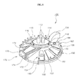
- Fig. 1 is a perspective view illustrating a roof for an electric furnace, according to the present invention.
- the electric furnace roof 100 includes a small-ceiling seating port 120 into which a small ceiling 110 is seated, and a large ceiling 130 which encloses the small ceiling 110.
- the small ceiling 110 is formed of castable refractories or concrete. Three electrode holes 114 into which respective electrode rods 112 are inserted are formed in the small ceiling 110.
- the electrode rods 112 are coupled to an electrode arm (not shown) which is provided above the small ceiling 110 so that vertical movement of the electrode rods 112 can be automatically adjusted while the electric furnace is operated, whereby an arc distance between lower ends of the electrode rods 112 and an upper surface of molten filling can be maintained constant.
- the small-ceiling seating port 120 into which the small ceiling 110 is seated has an annular shape and is oriented horizontally. As shown in Fig. 2 , a small-ceiling seating surface 122 is formed on an upper end of the small-ceiling seating port 120. A small-ceiling support surface 124 is formed in an inner circumferential surface of the small-ceiling seating port 120. The small-ceiling support surface 124 is formed in such a way that the diameter thereof is reduced from the top of the inner circumferential surface of the small-ceiling seating port 120 to the bottom thereof. A shell 116 which is provided enclosing an outer circumferential surface of small ceiling 120 is brought into close contact with the small-ceiling support surface 124. Stop protrusions 118 are provided on the shell 116 and are placed on the small-ceiling seating surface 122.
- the large ceiling 130 includes an upper roof panel 132, a lower roof panel 134 which is spaced apart from the upper roof panel 132, and a side roof panel 136 which is connected both to an extension edge of the upper roof panel 132 and to an extension edge of the lower roof panel 134 in such a way that the side roof panel 136 encloses the extension edges of the upper and lower roof panels 132 and 134.
- the upper roof panel 132 radially extends outwards from an outer circumferential surface of the small-ceiling seating port 120 at a downward inclination angle.
- the lower roof panel 134 radially extends outwards from a lower end of the small-ceiling support surface 124 at a downward inclination angle.
- an angle ⁇ between the lower roof panel 134 and the bottom of the large ceiling 130 is increased.
- a height H of the top of the large ceiling 130 is increased.
- the angle ⁇ ranges from 19° to 25° and, preferably, it ranges from 20.1° to 20.5°.
- Slag catchers 138 are provided on a surface of the lower roof panel 134 that faces molten metal.
- a coating layer 139 and a heat resistance layer 140 are successively formed on the lower roof panel 134 on which the slag catchers 138 are provided. The slag catchers 138, the coating layer 139 and the heat resistance layer 140 prevent the lower roof panel 134 from being damaged by heat transferred from the molten metal.
- each slag catcher 138 is an approximately "U" shaped to catch slag and prevent the caught slag from easily flowing downwards.
- the coating layer 139 is formed of at least one selected from among Al, Ni, Cr, an Al alloy, a Ni alloy, a Cr alloy and an ultra heat resistant alloy by spray coating.
- the heat resistance layer 140 is formed of ceramic that is a heat resistant material applied by either spray coating or enamel coating.
- a cooling passage 142 is formed in the large ceiling 130, that is, in the side roof panel 136, the lower roof panel 134 and the upper roof panel 132, to cool heat transferred from the electric furnace.
- a plurality of injection pipes 144 which discharge cooling fluid are arranged in the cooling passage 142.
- the injection pipes 144 of the cooling passage 142 are connected to each other and are radially arranged in the cooling passage 142.
- At least one of the injection pipes 144 is connected to a cooling fluid supply pipe 146 through which cooling fluid is supplied from the outside into the cooling passage 142. Cooling fluid that has been injected into the cooling passage 142 is discharged out of the cooling passage 142 through a cooling fluid discharge pipe 148.
- the cooling fluid supply pipe 146 is connected to the injection pipes 144 through the side roof panel 136, and the cooling fluid discharge pipe 148 is preferably provided on the side roof panel 136.
- inspection holes 150 are formed in the upper roof panel 132 at positions corresponding to the respective injection pipes 144.
- the inspection holes 150 are covered with respective inspection hole covers 152.
- Each inspection hole cover 152 is rotatably connected to the upper roof panel 132 by a hinge.
- a safety structure 154 and a lift structure 170 are further provided on the large ceiling 130. Also, a dust collection elbow 184 and an auxiliary raw material inlet 186 are provided on the large ceiling 130.
- the safety structure 154 is provided on the large ceiling 130 to secure the safety of a worker when conducting the work of repairing the roof 100.
- the safety structure 154 includes a plurality of support rods 156, each of which has a vertical cylindrical shape, and a banister 164 which is selectively fitted into the support rods 156.
- the support rods 156 are vertically provided on the perimeter of the upper roof panel 132 at positions spaced apart from each other at regular intervals.
- a cooling pipe 158 is coupled to the support rods 156 to cool heat transferred from the electric furnace.
- the cooling pipe 158 is disposed in such a way that it horizontally connects one support rod 156 to another adjacent support rod 156.
- Another cooling water supply pipe 160 is connected to the cooling pipe 158 to supply cooling water from the outside thereto.
- Another cooling water discharge pipe 162 is connected to the cooling pipe 158 to discharge cooling water out of the cooling pipe 158.
- the banister 164 is selectively fitted into the support rods 156 to which the cooling pipe 158 is coupled.
- the banister 164 includes a pair of vertical legs 166 which are respectively fitted into one support rod 156 and another adjacent support rod 156, and at least one horizontal beam 168 which connects upper ends of the vertical legs 166 to each other. Only when the work of repairing the roof 100 is conducted is the banister 164 inserted into two selected support rods 156 by the worker. In other words, the worker installs the banister 164 on the corresponding support rods 156 adjacent to a task location so as to protect himself/herself from danger, e.g., falling from the roof 100.
- the lift structure 170 is provided on the large ceiling 130 to make it possible to lift the roof 100.
- a lift cylinder (not shown) which is disposed outside the roof 100 is connected to the lift structure 170.
- the lift structure 170 is installed on the roof 100 with a balanced center of gravity such that the roof 100 is not tilted to one side.
- the lift structure 170 includes a horizontal support arm 172 and a vertical support arm 174.
- the horizontal support arm 172 comprises a pair of horizontal support arms 172.
- the horizontal support arms 172 horizontally extend from a portion the upper roof panel 132 that is adjacent to the small-ceiling seating port 120 towards the perimeter of the upper roof panel 132.
- the vertical support arm 174 comprises a pair of vertical support arms 174 which are provided on the perimeter of the upper roof panel 132.
- the vertical support arms 174 are connected to the horizontal support arms 172 that extend towards the perimeter of the upper roof panel 132, thus supporting the horizontal support arms 172.
- a connection block 176 is coupled to outer surfaces of the vertical support arms 174 so that the lift cylinder is connected to the connection block 176 when lifting the roof 100.
- the lift structure 170 includes an anti-dust unit 178.
- the anti-dust unit 178 functions to prevent dust from entering the lift structure 170 and accumulating therein and includes blocking panels 180 which block both sides of the lift structure 170, and a blocking cover 182 which blocks an upper portion of the lift structure 170.
- each blocking panel 180 is fixed to the outer surfaces of one of the horizontal support arms 172 and the corresponding adjacent vertical support arm 174 to prevent dust from entering the lift structure through space between the horizontal support arm 172 and the vertical support arm 174.
- the blocking cover 182 is disposed on the upper surfaces of the horizontal support arms 172 to prevent dust from entering the lift structure through space between the horizontal support arms 172.
- the blocking cover 182 that blocks the space between the horizontal support arms 172 is rotatably connected to either of the horizontal support arms 172 by a hinge.
- the inclination angle of the lower roof panel 134 of the large ceiling 130 is increased so that the height of the ceiling can be increased.
- a large amount of scrap iron can be put into the electric furnace.
- the slag catchers 138 are attached to the lower roof panel 134 and ceramic heat resistant paint 140 is applied thereto, whereby the lower roof panel 134 can be protected from sparks.
- the safety structure 154 which includes the support rods 156 and the banister 164 removably fitted into the support rods 156, is provided on the upper roof panel 132, thus preventing accidents such as a worker falling from the roof 100 when conducting the work of repairing the roof 100. Also, the safety structure 154 can provide a sense of safety to the worker who is doing work on the roof 100.
- the electric furnace roof 100 includes the anti-dust unit 178 which covers the upper portion and both side surfaces of the lift structure 170, thus preventing dust or the like from entering the lift structure 170 and accumulating therein. Therefore, the present invention can avoid a problem in which the worker must remove dust that has accumulated in the lift structure 170 so as to balance the center of gravity of the roof 100 when lifting the roof 100.
- roof for electric furnace 110 small ceiling 120: small-ceiling seating port 122: small-ceiling seating surface 124: small-ceiling support surface 130: large ceiling 132: upper roof panel 134: lower roof panel 136: side roof panel 142: cooling passage 144: injection pipe 150: inspection hole 152: inspection hole cover 154: safety structure 156: support rod 158: cooling pipe 164: banister 170: lift structure 178: anti-dust unit 180: blocking panel 182: blocking cover
Landscapes
- Engineering & Computer Science (AREA)
- Mechanical Engineering (AREA)
- General Engineering & Computer Science (AREA)
- Chemical & Material Sciences (AREA)
- Manufacturing & Machinery (AREA)
- Materials Engineering (AREA)
- Metallurgy (AREA)
- Organic Chemistry (AREA)
- Vertical, Hearth, Or Arc Furnaces (AREA)
- Furnace Housings, Linings, Walls, And Ceilings (AREA)
- Refinement Of Pig-Iron, Manufacture Of Cast Iron, And Steel Manufacture Other Than In Revolving Furnaces (AREA)
- Coating By Spraying Or Casting (AREA)
Abstract
Description
- The present invention relates, in general, to roofs for electric furnaces which open or close the electric furnaces and, more particularly, to a roof for an electric furnace which is configured such that the lifetime thereof can be extended and the safety and convenience of a worker can be provided when conducting the work of repairing the roof.
- Generally, electric furnaces are devices which manufacture steel in such a way that raw materials such as iron ore are melted and refined by arc heat generated between a plurality of electrode rods and scrap when current is applied to the electrode rods.
- In such an electric furnace, the roof which covers the electric furnace is opened, and raw material such as scrap is put into the electric furnace by a crane or the like. Thereafter, high voltage is applied to the electrode rods that are vertically connected to the roof after the roof covers the upper end of the electric furnace. Then, the raw material is melted by high-temperature arc heat. Molten steel which is formed by melting the raw material such as scrap iron is transferred into a teeming ladle through an outlet hole formed in a lower portion of the electric furnace. The teeming ladle filled with molten steel is transferred to a place for another process by a transport carrier.
- The above-mentioned roof effectively blocks and discharges a large amount of fumes which are generated in the electric furnace during the process of melting scrap or the like that has been put into the electric furnace. Also, the roof prevents noise from occurring during the melting process and blocks splash slag from scattering out of the electric furnace.
- An example of the prior art was proposed in Korean Utility Model Publication No.
1983-0003259 (Publication date: Dec. 12, 1983 - Accordingly, the present invention has been made keeping in mind the above problems occurring in the prior art, and an object of the present invention is to provide a roof for electric furnaces in which an inclination angle of a lower roof panel is increased, and ceramic heat resistant paint is applied to the lower roof panel, whereby the junction between the lower roof panel and a small-ceiling seating port can be prevented from being damaged by heat, and the lower roof panel can be protected from spark, thus improving the lifetime of the roof.
- Another object of the present invention is to provide a roof for electric furnaces which is provided with a safety structure to provide the safety of a worker when repairing the roof, thus preventing the worker from falling from the roof because of accidents during the work of repairing the roof.
- A further object of the present invention is to provide a roof for electric furnaces in which an anti-dust unit is installed on a lift structure that is provided on the upper roof panel and is connected to a lift cylinder when the roof is lifted, whereby the separate work of removing dust, which has accumulated in the lift structure, before the roof lifting process is not required.
- The objects of the present invention are not limited to the above objects.
- In order to accomplish the above objects, the present invention provides a roof for an electric furnace, including: a small-ceiling seating port having a small-ceiling seating surface provided horizontally and having an annular shape, and a small-ceiling support surface extending from an inner circumferential edge of the small-ceiling seating surface inwards and downwards in such a way that a diameter of the small-ceiling support surface is reduced from a top thereof to a bottom; and a large ceiling comprising an upper roof panel disposed enclosing the small-ceiling seating port and radially extending from the small-ceiling seating port at a downward inclination angle, a lower roof panel disposed below the upper roof panel at a position spaced apart from the upper roof panel by a predetermined distance, and a side roof panel connected both to an extension edge of the upper roof panel and to an extension edge of the lower roof panel in such a way that the side roof panel encloses the extension edges of the upper and lower roof panels, wherein the upper roof panel is connected to an outer circumferential surface of the small-ceiling seating port, and the lower roof panel is connected to a lower end of the small-ceiling support surface so that the inclination angle of the lower roof panel can be increased.
- Furthermore, a plurality of slag catchers may be provided on the lower roof panel, and a coating layer and a heat resistance layer may be successively formed on the lower roof panel having the slag catchers.
- In addition, a cooling passage may be provided among the side roof panel, the lower roof panel and the upper roof panel, and a plurality of injection pipes may be radially arranged in the cooling passage and connected to each other, the injection pipes discharging cooling fluid into the cooling passage. At least one of the injection pipes may be connected to a cooling fluid supply pipe through side roof panel, the cooling fluid supply pipe supplying cooling fluid into the cooling passage, and cooling fluid injected into the cooling passage may be discharged out of the cooling passage through a cooling fluid discharge pipe provided on the side roof panel.
- Inspection holes may be formed in the upper roof panel at positions corresponding to the respective injection pipes, and inspection hole covers may cover the respective inspection holes, each of the inspection hole covers being rotatably connected to the upper roof panel by a hinge.
- The large ceiling may further include a safety structure. The safety structure may include: a plurality of support rods arranged along a perimeter of the upper roof panel; and a banister having a pair of vertical legs respectively fitted into one of the support rods and another adjacent support rod, and a horizontal beam connecting upper ends of the vertical legs to each other.
- In detail, a cooling pipe may be coupled to the support rods to cool heat transferred from the electric furnace, the cooling pipe being disposed in such a way as to horizontally connect one of the support rods to another adjacent support rod, and a cooling water supply pipe for supplying cooling water into the cooling pipe and a cooling water discharge pipe for discharging the cooling water from the cooling pipe may be connected to the cooling pipe.
- The large ceiling may further include a lift structure. The lift structure may include a pair of horizontal support arms horizontally extending from a portion the upper roof panel that is adjacent to the small-ceiling seating port towards a perimeter of the upper roof panel; a pair of vertical support arms provided on the perimeter of the upper roof panel, the vertical support arms supporting the horizontal support arms; a connection block coupled to outer surfaces of the vertical support arms so that when the roof is lifted, the connection block being connected to a lift cylinder disposed outside the roof; and an anti-dust unit preventing dust from entering the lift structure.
- The anti-dust unit may include: a blocking panel provided on outer side surfaces of the horizontal support arms and the vertical support arms; and a blocking cover disposed on upper surfaces of the horizontal support arms, wherein the blocking cover is rotatably coupled to either of the horizontal support arms by a hinge and blocks a space between the horizontal support arms.
- A roof for electric furnaces according to the present invention has the following effects.
- First, an inclination angle of a lower roof panel is increased so that the height of the ceiling can be increased. Thereby, a large amount of scrap iron can be put into the electric furnace. Furthermore, because the distance between a heat source and the junction between the lower roof panel and a small-ceiling seating port is increased, the junction can be prevented from being damaged by heat. As a result, it is expected that the lifetime of the roof can be extended.
- Second, a small-ceiling support surface of the small-ceiling seating port is on the same level, and the lower roof panel is connected to the small-ceiling support surface. Therefore, repair work for the junction between the small-ceiling support surface and the lower roof panel can be facilitated, and the repair period can be reduced.
- Third, ceramic heat resistant paint is applied to the lower roof panel so that the lower roof panel can be protected from spark, thus increasing the lifetime of the roof.
- Fourth, a safety structure, which includes support rods and a banister removably fitted to the support rods, is provided on an upper roof panel, thus preventing accidents such as a worker falling from the roof when repairing the roof. Also, the safety structure can provide a sense of safety to the worker who is doing work on the roof.
- Fifth, the roof is provided with an anti-dust unit which covers an upper portion and both side surfaces of the lift structure, thus preventing dust or the like from entering the lift structure and accumulating therein. Therefore, the present invention can avoid a problem in which the worker must remove dust that has accumulated in the lift structure so as to balance the center of gravity of the roof when lifting the roof.
-
-
Fig. 1 is a perspective view illustrating a roof for an electric furnace, according to the present invention, -
Fig. 2 is a partially sectional perspective view of the electric furnace roof ofFig. 1 according to the present invention, -
Fig. 3 is an enlarged view of portion "A" ofFig. 2 , -
Fig. 4 is a perspective view illustrating the coupling of a safety structure shown inFig. 1 to the electric furnace roof, and -
Fig. 5 is an enlarged perspective view of a lift structure shown inFig. 1 . - Hereinafter, the present invention will be described with reference to the attached drawings. Reference should now be made to the drawings, in which the same reference numerals are used throughout the different drawings to designate the same or similar components. If detailed descriptions of well-known functions or configurations would unnecessarily obfuscate the gist of the present invention, the detailed descriptions will be omitted.
-
Fig. 1 is a perspective view illustrating a roof for an electric furnace, according to the present invention. Theelectric furnace roof 100 includes a small-ceiling seating port 120 into which asmall ceiling 110 is seated, and alarge ceiling 130 which encloses thesmall ceiling 110. - The
small ceiling 110 is formed of castable refractories or concrete. Threeelectrode holes 114 into whichrespective electrode rods 112 are inserted are formed in thesmall ceiling 110. Theelectrode rods 112 are coupled to an electrode arm (not shown) which is provided above thesmall ceiling 110 so that vertical movement of theelectrode rods 112 can be automatically adjusted while the electric furnace is operated, whereby an arc distance between lower ends of theelectrode rods 112 and an upper surface of molten filling can be maintained constant. - The small-
ceiling seating port 120 into which thesmall ceiling 110 is seated has an annular shape and is oriented horizontally. As shown inFig. 2 , a small-ceiling seating surface 122 is formed on an upper end of the small-ceiling seating port 120. A small-ceiling support surface 124 is formed in an inner circumferential surface of the small-ceiling seating port 120. The small-ceiling support surface 124 is formed in such a way that the diameter thereof is reduced from the top of the inner circumferential surface of the small-ceiling seating port 120 to the bottom thereof. Ashell 116 which is provided enclosing an outer circumferential surface ofsmall ceiling 120 is brought into close contact with the small-ceiling support surface 124.Stop protrusions 118 are provided on theshell 116 and are placed on the small-ceiling seating surface 122. - The
large ceiling 130 includes anupper roof panel 132, alower roof panel 134 which is spaced apart from theupper roof panel 132, and aside roof panel 136 which is connected both to an extension edge of theupper roof panel 132 and to an extension edge of thelower roof panel 134 in such a way that theside roof panel 136 encloses the extension edges of the upper andlower roof panels upper roof panel 132 radially extends outwards from an outer circumferential surface of the small-ceiling seating port 120 at a downward inclination angle. In a similar manner, thelower roof panel 134 radially extends outwards from a lower end of the small-ceiling support surface 124 at a downward inclination angle. Because thelower roof panel 134 is directly connected to the lower end of the small-ceiling support surface 124, an angle θ between thelower roof panel 134 and the bottom of thelarge ceiling 130 is increased. As a result, a height H of the top of thelarge ceiling 130 is increased. The angle θ ranges from 19° to 25° and, preferably, it ranges from 20.1° to 20.5°.Slag catchers 138 are provided on a surface of thelower roof panel 134 that faces molten metal. Acoating layer 139 and aheat resistance layer 140 are successively formed on thelower roof panel 134 on which theslag catchers 138 are provided. Theslag catchers 138, thecoating layer 139 and theheat resistance layer 140 prevent thelower roof panel 134 from being damaged by heat transferred from the molten metal. - As shown in the drawings, each
slag catcher 138 is an approximately "U" shaped to catch slag and prevent the caught slag from easily flowing downwards. Thecoating layer 139 is formed of at least one selected from among Al, Ni, Cr, an Al alloy, a Ni alloy, a Cr alloy and an ultra heat resistant alloy by spray coating. Theheat resistance layer 140 is formed of ceramic that is a heat resistant material applied by either spray coating or enamel coating. - Meanwhile, a
cooling passage 142 is formed in thelarge ceiling 130, that is, in theside roof panel 136, thelower roof panel 134 and theupper roof panel 132, to cool heat transferred from the electric furnace. A plurality ofinjection pipes 144 which discharge cooling fluid are arranged in thecooling passage 142. Theinjection pipes 144 of thecooling passage 142 are connected to each other and are radially arranged in thecooling passage 142. At least one of theinjection pipes 144 is connected to a coolingfluid supply pipe 146 through which cooling fluid is supplied from the outside into thecooling passage 142. Cooling fluid that has been injected into thecooling passage 142 is discharged out of thecooling passage 142 through a coolingfluid discharge pipe 148. The coolingfluid supply pipe 146 is connected to theinjection pipes 144 through theside roof panel 136, and the coolingfluid discharge pipe 148 is preferably provided on theside roof panel 136. As shown inFig. 2 , inspection holes 150 are formed in theupper roof panel 132 at positions corresponding to therespective injection pipes 144. The inspection holes 150 are covered with respective inspection hole covers 152. Eachinspection hole cover 152 is rotatably connected to theupper roof panel 132 by a hinge. - A
safety structure 154 and alift structure 170 are further provided on thelarge ceiling 130. Also, adust collection elbow 184 and an auxiliaryraw material inlet 186 are provided on thelarge ceiling 130. - The
safety structure 154 is provided on thelarge ceiling 130 to secure the safety of a worker when conducting the work of repairing theroof 100. As shown inFIG. 4 , thesafety structure 154 includes a plurality ofsupport rods 156, each of which has a vertical cylindrical shape, and abanister 164 which is selectively fitted into thesupport rods 156. - The
support rods 156 are vertically provided on the perimeter of theupper roof panel 132 at positions spaced apart from each other at regular intervals. A coolingpipe 158 is coupled to thesupport rods 156 to cool heat transferred from the electric furnace. Thecooling pipe 158 is disposed in such a way that it horizontally connects onesupport rod 156 to anotheradjacent support rod 156. Another coolingwater supply pipe 160 is connected to thecooling pipe 158 to supply cooling water from the outside thereto. Another coolingwater discharge pipe 162 is connected to thecooling pipe 158 to discharge cooling water out of thecooling pipe 158. Thebanister 164 is selectively fitted into thesupport rods 156 to which thecooling pipe 158 is coupled. - The
banister 164 includes a pair ofvertical legs 166 which are respectively fitted into onesupport rod 156 and anotheradjacent support rod 156, and at least onehorizontal beam 168 which connects upper ends of thevertical legs 166 to each other. Only when the work of repairing theroof 100 is conducted is thebanister 164 inserted into two selectedsupport rods 156 by the worker. In other words, the worker installs thebanister 164 on thecorresponding support rods 156 adjacent to a task location so as to protect himself/herself from danger, e.g., falling from theroof 100. - The
lift structure 170 is provided on thelarge ceiling 130 to make it possible to lift theroof 100. When it is required to lift theroof 100, a lift cylinder (not shown) which is disposed outside theroof 100 is connected to thelift structure 170. Thelift structure 170 is installed on theroof 100 with a balanced center of gravity such that theroof 100 is not tilted to one side. - As shown in
Fig. 5 , thelift structure 170 includes ahorizontal support arm 172 and avertical support arm 174. Thehorizontal support arm 172 comprises a pair ofhorizontal support arms 172. Thehorizontal support arms 172 horizontally extend from a portion theupper roof panel 132 that is adjacent to the small-ceiling seating port 120 towards the perimeter of theupper roof panel 132. Thevertical support arm 174 comprises a pair ofvertical support arms 174 which are provided on the perimeter of theupper roof panel 132. Thevertical support arms 174 are connected to thehorizontal support arms 172 that extend towards the perimeter of theupper roof panel 132, thus supporting thehorizontal support arms 172. Aconnection block 176 is coupled to outer surfaces of thevertical support arms 174 so that the lift cylinder is connected to theconnection block 176 when lifting theroof 100. - The
lift structure 170 includes ananti-dust unit 178. Theanti-dust unit 178 functions to prevent dust from entering thelift structure 170 and accumulating therein and includes blockingpanels 180 which block both sides of thelift structure 170, and a blockingcover 182 which blocks an upper portion of thelift structure 170. As shown in the drawing, each blockingpanel 180 is fixed to the outer surfaces of one of thehorizontal support arms 172 and the corresponding adjacentvertical support arm 174 to prevent dust from entering the lift structure through space between thehorizontal support arm 172 and thevertical support arm 174. The blockingcover 182 is disposed on the upper surfaces of thehorizontal support arms 172 to prevent dust from entering the lift structure through space between thehorizontal support arms 172. The blockingcover 182 that blocks the space between thehorizontal support arms 172 is rotatably connected to either of thehorizontal support arms 172 by a hinge. - In the
electric furnace roof 100 according to the present invention having the above-mentioned construction, the inclination angle of thelower roof panel 134 of thelarge ceiling 130 is increased so that the height of the ceiling can be increased. Thereby, a large amount of scrap iron can be put into the electric furnace. Furthermore, because the distance between a heat source and the junction between thelower roof panel 134 and the small-ceiling seating port 120 is increased, the junction can be prevented from being damaged by heat. Theslag catchers 138 are attached to thelower roof panel 134 and ceramic heatresistant paint 140 is applied thereto, whereby thelower roof panel 134 can be protected from sparks. - Further, in the
electric furnace roof 100 according to the present invention, thesafety structure 154, which includes thesupport rods 156 and thebanister 164 removably fitted into thesupport rods 156, is provided on theupper roof panel 132, thus preventing accidents such as a worker falling from theroof 100 when conducting the work of repairing theroof 100. Also, thesafety structure 154 can provide a sense of safety to the worker who is doing work on theroof 100. - Moreover, the
electric furnace roof 100 according to the present invention includes theanti-dust unit 178 which covers the upper portion and both side surfaces of thelift structure 170, thus preventing dust or the like from entering thelift structure 170 and accumulating therein. Therefore, the present invention can avoid a problem in which the worker must remove dust that has accumulated in thelift structure 170 so as to balance the center of gravity of theroof 100 when lifting theroof 100. - Although the preferred embodiment of the present invention has been disclosed for illustrative purposes, those skilled in the art will appreciate that various modifications, additions and substitutions are possible, without departing from the scope and spirit of the invention as disclosed in the accompanying claims.
-
100: roof for electric furnace 110: small ceiling 120: small-ceiling seating port 122: small-ceiling seating surface 124: small-ceiling support surface 130: large ceiling 132: upper roof panel 134: lower roof panel 136: side roof panel 142: cooling passage 144: injection pipe 150: inspection hole 152: inspection hole cover 154: safety structure 156: support rod 158: cooling pipe 164: banister 170: lift structure 178: anti-dust unit 180: blocking panel 182: blocking cover
Claims (11)
- A roof for an electric furnace, comprising:a seating port of annual shape that has a ceiling seating surface disposed horizontally and a ceiling support surface that extends from an inner circumferential edge of the ceiling seating surface inwards and downwards reducing a diameter of the ceiling support surface from a top thereof to a bottom; anda ceiling including:an upper roof panel that encloses the ceiling seating port and radially extends from the ceiling seating port at a downward inclination angle;a lower roof panel disposed below the upper roof panel at a position spaced apart from the upper roof panel by a predetermined distance; anda side roof panel connected to an extension edge of the upper roof panel and to an extension edge of the lower roof panel to enclose the extension edges of the upper and lower roof panels,wherein the upper roof panel is connected to an outer circumferential surface of the ceiling seating port, andwherein the lower roof panel is connected to a lower end of the ceiling support surface to increase the inclination angle of the lower roof panel.
- The roof for an electric furnace according to claim 1, further comprising:a plurality of slag catchers disposed on the lower roof panel; anda coating layer and a heat resistance layer successively formed on the lower roof panel that has the plurality of slag catchers.
- The roof for an electric furnace according to claim 2, wherein the coating layer is formed of at least one selected from a group consisting of: Aluminum (Al), Nickel (Ni), Chromium (Cr), an Al alloy, a Ni alloy, a Cr alloy and an ultra-heat resistant alloy by spray coating.
- The roof for an electric furnace according to claim 2, wherein the heat resistance layer is formed of ceramic that is a heat resistant material by either spray coating or enamel coating.
- The roof for an electric furnace according to claim 1, further comprising:a cooling passageway is provided among the side roof panel, the lower roof panel and the upper roof panel; anda plurality of injection pipes radially arranged within the cooling passageway and connected to each other, wherein the injection pipes discharge cooling fluid into the cooling passageway.
- The roof for an electric furnace according to claim 5, wherein
at least one of the injection pipes is connected to a cooling fluid supply pipe via the side roof panel,
the cooling fluid supply pipe supplies cooling fluid into the cooling passageway, and
cooling fluid injected into the cooling passageway is discharged out of the cooling passageway via a cooling fluid discharge pipe disposed on the side roof panel. - The roof for an electric furnace according to claim 5, further comprising:a plurality of inspection apertures formed in the upper roof panel at positions that correspond to the respective injection pipes; anda plurality of inspection aperture covers that cover the respective inspection apertures,wherein each of the inspection aperture covers are rotatably connected to the upper roof panel by a hinge.
- The roof for an electric furnace according to claim 1, wherein the ceiling further comprises a safety structure, the safety structure including:a plurality of support rods arranged along a perimeter of the upper roof panel; anda banister that has a pair of vertical legs respectively fitted into one of the support rods and another adjacent support rod, and a horizontal beam that connects upper ends of the vertical legs.
- The roof for an electric furnace according to claim 8, further comprising:a cooling pipe coupled to the support rods to cool heat transferred from the electric furnace, wherein the cooling pipe being horizontally connects one of the support rods to another adjacent support rod, anda cooling water supply pipe that supplies cooling water into the cooling pipe and a cooling water discharge pipe that discharges the cooling water from the cooling pipe are connected to the cooling pipe.
- The roof for an electric furnace according to claim 1, wherein the ceiling further comprises a lift structure, the lift structure including:a pair of horizontal support arms that extend horizontally from a portion of the upper roof panel adjacent to the ceiling seating port towards a perimeter of the upper roof panel;a pair of vertical support arms disposed on the perimeter of the upper roof panel, wherein the vertical support arms support the horizontal support arms;a connection block coupled to outer surfaces of the vertical support arms to connect the connection block to a lift cylinder disposed extraneous to the roof when the roof is lifted; andan anti-dust unit that prevents dust from entering the lift structure.
- The roof for an electric furnace according to claim 10, wherein the anti-dust unit includes:a blocking panel disposed on outer side surfaces of the horizontal support arms and the vertical support arms; anda blocking cover disposed on upper surfaces of the horizontal support arms, wherein the blocking cover is rotatably coupled to either of the horizontal support arms by a hinge and blocks a space between the horizontal support arms.
Applications Claiming Priority (4)
| Application Number | Priority Date | Filing Date | Title |
|---|---|---|---|
| KR20110028501 | 2011-03-30 | ||
| KR20110040074 | 2011-04-28 | ||
| KR1020110123634A KR101293060B1 (en) | 2011-03-30 | 2011-11-24 | Furnace Roof |
| PCT/KR2011/010138 WO2012134036A1 (en) | 2011-03-30 | 2011-12-27 | Roof for electric furnace |
Publications (3)
| Publication Number | Publication Date |
|---|---|
| EP2693144A1 true EP2693144A1 (en) | 2014-02-05 |
| EP2693144A4 EP2693144A4 (en) | 2014-09-17 |
| EP2693144B1 EP2693144B1 (en) | 2016-08-31 |
Family
ID=47282469
Family Applications (1)
| Application Number | Title | Priority Date | Filing Date |
|---|---|---|---|
| EP11862482.4A Not-in-force EP2693144B1 (en) | 2011-03-30 | 2011-12-27 | Roof for electric furnace |
Country Status (6)
| Country | Link |
|---|---|
| US (1) | US10132566B2 (en) |
| EP (1) | EP2693144B1 (en) |
| JP (1) | JP5719474B2 (en) |
| KR (1) | KR101293060B1 (en) |
| CN (1) | CN103459961B (en) |
| WO (1) | WO2012134036A1 (en) |
Cited By (1)
| Publication number | Priority date | Publication date | Assignee | Title |
|---|---|---|---|---|
| EP3824235A4 (en) * | 2018-07-17 | 2022-04-20 | Systems Spray-Cooled, Inc. | Metallurgical furnace having an integrated off-gas hood |
Families Citing this family (11)
| Publication number | Priority date | Publication date | Assignee | Title |
|---|---|---|---|---|
| WO2016126801A1 (en) * | 2015-02-04 | 2016-08-11 | E I Du Pont De Nemours And Company | Conductive paste composition and semiconductor devices made therewith |
| JP6693669B2 (en) * | 2015-03-12 | 2020-05-13 | ホヤ レンズ タイランド リミテッドHOYA Lens Thailand Ltd | Method for storing isocyanate compound |
| US10488114B1 (en) * | 2015-06-09 | 2019-11-26 | Materion Corporation | Fluid-cooled copper lid for arc furnace |
| KR101669403B1 (en) | 2016-07-04 | 2016-10-26 | 주식회사 청우기연 | roof cover improved heat reservance for electric furnace |
| US10598436B2 (en) * | 2017-04-18 | 2020-03-24 | Systems Spray-Cooled, Inc. | Cooling system for a surface of a metallurgical furnace |
| CN110186284A (en) * | 2019-05-20 | 2019-08-30 | 河南天利热工装备股份有限公司 | A kind of electric pushrod lifting furnace cover structure |
| KR102187418B1 (en) * | 2019-09-23 | 2020-12-08 | 주식회사 엠텍 | Roof apparatus of ladle furnace |
| JP2024518144A (en) * | 2021-04-15 | 2024-04-25 | シエル・インターナシヨネイル・リサーチ・マーチヤツピイ・ベー・ウイ | Electric heating device |
| US12442596B2 (en) * | 2022-03-02 | 2025-10-14 | Systems Spray-Cooled, Inc. | Spray-cooled furnace roof with gravity drain |
| KR20230134044A (en) | 2022-03-11 | 2023-09-20 | 이근홍 | Automatic opening and closing device for electric furnace cover |
| US20250271212A1 (en) * | 2024-02-22 | 2025-08-28 | Systems Spray-Cooled, Inc. | Metallurgical furnace hot plate with cooling features |
Family Cites Families (32)
| Publication number | Priority date | Publication date | Assignee | Title |
|---|---|---|---|---|
| US3053237A (en) * | 1959-11-02 | 1962-09-11 | Sunrod Mfg Corp | Furnace lining |
| US3555163A (en) * | 1969-05-16 | 1971-01-12 | United States Steel Corp | Fume-exhaust hood for electric furnace |
| GB1331459A (en) * | 1970-12-22 | 1973-09-26 | Steetley Mfg Ltd | Furnace construction |
| US3967048A (en) * | 1975-06-06 | 1976-06-29 | Longenecker Levi S | Dual ring supported roof for electric arc furnace |
| US4021603A (en) * | 1975-10-22 | 1977-05-03 | Ishikawajima-Harima Jukogyo Kabushiki Kaisha | Roof for arc furnace |
| US4182610A (en) * | 1977-02-08 | 1980-01-08 | Daidotokushuko Kabushikikaisha | Water-cooled furnace cover |
| US4273949A (en) * | 1979-04-17 | 1981-06-16 | Fried. Krupp Huttenwerke Aktiengesellschaft | Arc furnace roof |
| US4644558A (en) * | 1983-06-24 | 1987-02-17 | Wean United, Inc. | Roof assembly for an electric arc furnace |
| JPS6013014A (en) | 1983-06-30 | 1985-01-23 | Ishikawajima Harima Heavy Ind Co Ltd | Ladle refining equipment |
| US4633480A (en) * | 1984-08-16 | 1986-12-30 | Fuchs Systems, Inc. | Liquid cooled cover for electric arc furnace |
| CA1257473A (en) * | 1984-10-12 | 1989-07-18 | Willard Mcclintock | Furnace cooling system and method |
| JPS6345672Y2 (en) | 1985-02-05 | 1988-11-28 | ||
| US4815096A (en) * | 1988-03-08 | 1989-03-21 | Union Carbide Corporation | Cooling system and method for molten material handling vessels |
| US4849987A (en) * | 1988-10-19 | 1989-07-18 | Union Carbide Corporation | Combination left and right handed furnace roof |
| DE4103508A1 (en) * | 1991-02-06 | 1992-08-13 | Kortec Ag | METHOD AND DEVICE FOR COOLING VESSEL PARTS FOR CARRYING OUT PYRO METHODS, IN PARTICULAR METALLURGICAL TYPE |
| US5115184A (en) * | 1991-03-28 | 1992-05-19 | Ucar Carbon Technology Corporation | Cooling system for furnace roof having a removable delta |
| JPH05140666A (en) * | 1991-11-19 | 1993-06-08 | Daido Steel Co Ltd | Electric furnace operating method and electric furnace |
| US5444734A (en) * | 1993-02-18 | 1995-08-22 | Ucar Carbon Technology Corporation | Device for lifting and moving the roof of a spray cooled furnace |
| JPH09273870A (en) * | 1996-04-03 | 1997-10-21 | Daido Steel Co Ltd | Water cooling furnace lid |
| US5887017A (en) * | 1996-09-27 | 1999-03-23 | Ucar Carbon Technology Corporation | Panelized spray-cooled furnace roof |
| IT1291117B1 (en) * | 1997-03-25 | 1998-12-29 | Acciai Speciali Terni Spa | DEVICE FOR THE PROTECTION OF GRAPHITE ELECTRODES IN METALLURGIC ELECTRIC OVENS |
| KR200181923Y1 (en) | 1999-12-22 | 2000-05-15 | 포항종합제철주식회사 | Anti-crevice apparatus of tranion ring cotter pin and core liner of converter |
| JP2001194070A (en) * | 2000-01-07 | 2001-07-17 | Godo Steel Ltd | Furnace lid for electric furnace |
| CN2514003Y (en) * | 2001-12-21 | 2002-10-02 | 烟台冶金水冷件厂 | Drain pipe water cooling furnace lid for steel-smelting electric furnace |
| US6870873B2 (en) * | 2003-05-28 | 2005-03-22 | Systems Spray-Cooled, Inc. | Device for improved slag retention in water cooled furnace elements |
| WO2006080269A1 (en) * | 2005-01-25 | 2006-08-03 | Toho Titanium Co., Ltd. | Apparatus for melting metal by electron beams and process for producing high-melting metal ingot using this apparatus |
| CN1818084A (en) * | 2006-03-10 | 2006-08-16 | 刘成龙 | Spraying and water-cooling furnace top cover |
| EP1881285A1 (en) * | 2006-07-20 | 2008-01-23 | Vesuvius Crucible Company | Ceiling of an electric arc furnace and central part thereof |
| KR101186198B1 (en) | 2007-08-13 | 2012-10-08 | 주식회사 포스코 | Apparatus for protecting electrode holder and electric furnace using the same |
| CN201292377Y (en) * | 2008-11-25 | 2009-08-19 | 长春电炉成套设备有限责任公司 | Electric-arc steel furnace |
| KR101026515B1 (en) | 2010-03-19 | 2011-04-01 | 주식회사 엠텍이엔지 | Ladle furnace roof device |
| CN201621962U (en) * | 2010-04-20 | 2010-11-03 | 西安同欣电热设备有限公司 | A Composite Furnace Roof of a Large Zinc Powder Submerged Thermal Electric Furnace |
-
2011
- 2011-11-24 KR KR1020110123634A patent/KR101293060B1/en not_active Expired - Fee Related
- 2011-12-27 EP EP11862482.4A patent/EP2693144B1/en not_active Not-in-force
- 2011-12-27 JP JP2014502438A patent/JP5719474B2/en not_active Expired - Fee Related
- 2011-12-27 WO PCT/KR2011/010138 patent/WO2012134036A1/en not_active Ceased
- 2011-12-27 CN CN201180069762.1A patent/CN103459961B/en not_active Expired - Fee Related
-
2013
- 2013-09-27 US US14/040,369 patent/US10132566B2/en active Active
Cited By (3)
| Publication number | Priority date | Publication date | Assignee | Title |
|---|---|---|---|---|
| EP3824235A4 (en) * | 2018-07-17 | 2022-04-20 | Systems Spray-Cooled, Inc. | Metallurgical furnace having an integrated off-gas hood |
| US11815313B2 (en) | 2018-07-17 | 2023-11-14 | Systems Spray-Cooled, Inc. | Metallurgical furnace having an integrated off-gas hood |
| US12292237B2 (en) | 2018-07-17 | 2025-05-06 | Systems Spray-Cooled, Inc. | Metallurgical furnace having an integrated off-gas hood |
Also Published As
| Publication number | Publication date |
|---|---|
| EP2693144A4 (en) | 2014-09-17 |
| KR101293060B1 (en) | 2013-08-05 |
| CN103459961A (en) | 2013-12-18 |
| US10132566B2 (en) | 2018-11-20 |
| EP2693144B1 (en) | 2016-08-31 |
| WO2012134036A1 (en) | 2012-10-04 |
| JP5719474B2 (en) | 2015-05-20 |
| CN103459961B (en) | 2015-10-14 |
| KR20120111892A (en) | 2012-10-11 |
| US20140029643A1 (en) | 2014-01-30 |
| JP2014515085A (en) | 2014-06-26 |
Similar Documents
| Publication | Publication Date | Title |
|---|---|---|
| EP2693144B1 (en) | Roof for electric furnace | |
| KR101141320B1 (en) | Melting furnace, in particular electric arc furnace | |
| US9618266B2 (en) | Ladle metallurgy furnace having improved roof | |
| US20170122665A1 (en) | Station and Method for Transferring a Metal Melt from a Melting Furnace to a Transport Crucible, and Arrangement Having Such a Station | |
| AU2024203512A1 (en) | Split roof for a metallurgical furnace | |
| US10598436B2 (en) | Cooling system for a surface of a metallurgical furnace | |
| KR101235614B1 (en) | Apparatus for lifting of ladle | |
| US20130322485A1 (en) | Burner insert for an arc furnace | |
| CN105671244A (en) | Spherical hinge support replacement method for 120-ton or above converter | |
| CN211522247U (en) | System for blowing argon to refine high manganese steel | |
| CN204702510U (en) | A kind of furnace of calcium carbide drawing mechanism | |
| CA2521705A1 (en) | Direct smelting plant | |
| JP6361622B2 (en) | Protective member for converter discharge, converter equipment and converter refining method | |
| CN213090488U (en) | Ou ye stove stave water pipe protection device | |
| KR100950365B1 (en) | Furnace with loop of multistage structure | |
| CN223138301U (en) | A charging port device for the top of a reverberatory furnace | |
| CN210254213U (en) | Brick cup repairing device for air brick | |
| CN205576205U (en) | Vacuum tank structure for RH | |
| CN217709532U (en) | Anti-splashing residual iron discharging device for blast furnace | |
| CN222182322U (en) | A protective device for arc furnace electrode lifting mechanism | |
| CN220270069U (en) | Slag blocking protection device for smelting furnace | |
| CN102392100A (en) | Converter alloy charging mechanism | |
| US20230175779A1 (en) | Side-supported cantilever furnace roof | |
| RU2373468C2 (en) | Arched steel furnace of small capacity | |
| ITRM20090576A1 (en) | FULLY MODULAR ALUMINUM ALLOY FOUNDATION PLANT. |
Legal Events
| Date | Code | Title | Description |
|---|---|---|---|
| PUAI | Public reference made under article 153(3) epc to a published international application that has entered the european phase |
Free format text: ORIGINAL CODE: 0009012 |
|
| 17P | Request for examination filed |
Effective date: 20130930 |
|
| AK | Designated contracting states |
Kind code of ref document: A1 Designated state(s): AL AT BE BG CH CY CZ DE DK EE ES FI FR GB GR HR HU IE IS IT LI LT LU LV MC MK MT NL NO PL PT RO RS SE SI SK SM TR |
|
| DAX | Request for extension of the european patent (deleted) | ||
| A4 | Supplementary search report drawn up and despatched |
Effective date: 20140814 |
|
| RIC1 | Information provided on ipc code assigned before grant |
Ipc: F27B 14/12 20060101ALI20140808BHEP Ipc: F27D 1/18 20060101ALI20140808BHEP Ipc: F27D 1/02 20060101AFI20140808BHEP Ipc: F27B 3/16 20060101ALI20140808BHEP Ipc: F27B 3/08 20060101ALI20140808BHEP Ipc: C21C 5/52 20060101ALI20140808BHEP Ipc: F27D 1/12 20060101ALI20140808BHEP |
|
| GRAP | Despatch of communication of intention to grant a patent |
Free format text: ORIGINAL CODE: EPIDOSNIGR1 |
|
| INTG | Intention to grant announced |
Effective date: 20160317 |
|
| GRAS | Grant fee paid |
Free format text: ORIGINAL CODE: EPIDOSNIGR3 |
|
| GRAA | (expected) grant |
Free format text: ORIGINAL CODE: 0009210 |
|
| AK | Designated contracting states |
Kind code of ref document: B1 Designated state(s): AL AT BE BG CH CY CZ DE DK EE ES FI FR GB GR HR HU IE IS IT LI LT LU LV MC MK MT NL NO PL PT RO RS SE SI SK SM TR |
|
| REG | Reference to a national code |
Ref country code: CH Ref legal event code: EP Ref country code: GB Ref legal event code: FG4D |
|
| REG | Reference to a national code |
Ref country code: IE Ref legal event code: FG4D |
|
| REG | Reference to a national code |
Ref country code: DE Ref legal event code: R096 Ref document number: 602011029978 Country of ref document: DE |
|
| REG | Reference to a national code |
Ref country code: AT Ref legal event code: REF Ref document number: 825371 Country of ref document: AT Kind code of ref document: T Effective date: 20161015 |
|
| REG | Reference to a national code |
Ref country code: LT Ref legal event code: MG4D |
|
| REG | Reference to a national code |
Ref country code: NL Ref legal event code: MP Effective date: 20160831 |
|
| PG25 | Lapsed in a contracting state [announced via postgrant information from national office to epo] |
Ref country code: HR Free format text: LAPSE BECAUSE OF FAILURE TO SUBMIT A TRANSLATION OF THE DESCRIPTION OR TO PAY THE FEE WITHIN THE PRESCRIBED TIME-LIMIT Effective date: 20160831 Ref country code: NO Free format text: LAPSE BECAUSE OF FAILURE TO SUBMIT A TRANSLATION OF THE DESCRIPTION OR TO PAY THE FEE WITHIN THE PRESCRIBED TIME-LIMIT Effective date: 20161130 Ref country code: LT Free format text: LAPSE BECAUSE OF FAILURE TO SUBMIT A TRANSLATION OF THE DESCRIPTION OR TO PAY THE FEE WITHIN THE PRESCRIBED TIME-LIMIT Effective date: 20160831 Ref country code: FI Free format text: LAPSE BECAUSE OF FAILURE TO SUBMIT A TRANSLATION OF THE DESCRIPTION OR TO PAY THE FEE WITHIN THE PRESCRIBED TIME-LIMIT Effective date: 20160831 Ref country code: RS Free format text: LAPSE BECAUSE OF FAILURE TO SUBMIT A TRANSLATION OF THE DESCRIPTION OR TO PAY THE FEE WITHIN THE PRESCRIBED TIME-LIMIT Effective date: 20160831 |
|
| PG25 | Lapsed in a contracting state [announced via postgrant information from national office to epo] |
Ref country code: LV Free format text: LAPSE BECAUSE OF FAILURE TO SUBMIT A TRANSLATION OF THE DESCRIPTION OR TO PAY THE FEE WITHIN THE PRESCRIBED TIME-LIMIT Effective date: 20160831 Ref country code: NL Free format text: LAPSE BECAUSE OF FAILURE TO SUBMIT A TRANSLATION OF THE DESCRIPTION OR TO PAY THE FEE WITHIN THE PRESCRIBED TIME-LIMIT Effective date: 20160831 Ref country code: GR Free format text: LAPSE BECAUSE OF FAILURE TO SUBMIT A TRANSLATION OF THE DESCRIPTION OR TO PAY THE FEE WITHIN THE PRESCRIBED TIME-LIMIT Effective date: 20161201 Ref country code: SE Free format text: LAPSE BECAUSE OF FAILURE TO SUBMIT A TRANSLATION OF THE DESCRIPTION OR TO PAY THE FEE WITHIN THE PRESCRIBED TIME-LIMIT Effective date: 20160831 Ref country code: ES Free format text: LAPSE BECAUSE OF FAILURE TO SUBMIT A TRANSLATION OF THE DESCRIPTION OR TO PAY THE FEE WITHIN THE PRESCRIBED TIME-LIMIT Effective date: 20160831 |
|
| PG25 | Lapsed in a contracting state [announced via postgrant information from national office to epo] |
Ref country code: EE Free format text: LAPSE BECAUSE OF FAILURE TO SUBMIT A TRANSLATION OF THE DESCRIPTION OR TO PAY THE FEE WITHIN THE PRESCRIBED TIME-LIMIT Effective date: 20160831 Ref country code: RO Free format text: LAPSE BECAUSE OF FAILURE TO SUBMIT A TRANSLATION OF THE DESCRIPTION OR TO PAY THE FEE WITHIN THE PRESCRIBED TIME-LIMIT Effective date: 20160831 |
|
| PG25 | Lapsed in a contracting state [announced via postgrant information from national office to epo] |
Ref country code: SK Free format text: LAPSE BECAUSE OF FAILURE TO SUBMIT A TRANSLATION OF THE DESCRIPTION OR TO PAY THE FEE WITHIN THE PRESCRIBED TIME-LIMIT Effective date: 20160831 Ref country code: BE Free format text: LAPSE BECAUSE OF FAILURE TO SUBMIT A TRANSLATION OF THE DESCRIPTION OR TO PAY THE FEE WITHIN THE PRESCRIBED TIME-LIMIT Effective date: 20160831 Ref country code: BG Free format text: LAPSE BECAUSE OF FAILURE TO SUBMIT A TRANSLATION OF THE DESCRIPTION OR TO PAY THE FEE WITHIN THE PRESCRIBED TIME-LIMIT Effective date: 20161130 Ref country code: DK Free format text: LAPSE BECAUSE OF FAILURE TO SUBMIT A TRANSLATION OF THE DESCRIPTION OR TO PAY THE FEE WITHIN THE PRESCRIBED TIME-LIMIT Effective date: 20160831 Ref country code: PT Free format text: LAPSE BECAUSE OF FAILURE TO SUBMIT A TRANSLATION OF THE DESCRIPTION OR TO PAY THE FEE WITHIN THE PRESCRIBED TIME-LIMIT Effective date: 20170102 Ref country code: CZ Free format text: LAPSE BECAUSE OF FAILURE TO SUBMIT A TRANSLATION OF THE DESCRIPTION OR TO PAY THE FEE WITHIN THE PRESCRIBED TIME-LIMIT Effective date: 20160831 Ref country code: SM Free format text: LAPSE BECAUSE OF FAILURE TO SUBMIT A TRANSLATION OF THE DESCRIPTION OR TO PAY THE FEE WITHIN THE PRESCRIBED TIME-LIMIT Effective date: 20160831 Ref country code: PL Free format text: LAPSE BECAUSE OF FAILURE TO SUBMIT A TRANSLATION OF THE DESCRIPTION OR TO PAY THE FEE WITHIN THE PRESCRIBED TIME-LIMIT Effective date: 20160831 |
|
| REG | Reference to a national code |
Ref country code: DE Ref legal event code: R097 Ref document number: 602011029978 Country of ref document: DE |
|
| PG25 | Lapsed in a contracting state [announced via postgrant information from national office to epo] |
Ref country code: IT Free format text: LAPSE BECAUSE OF FAILURE TO SUBMIT A TRANSLATION OF THE DESCRIPTION OR TO PAY THE FEE WITHIN THE PRESCRIBED TIME-LIMIT Effective date: 20160831 |
|
| PLBE | No opposition filed within time limit |
Free format text: ORIGINAL CODE: 0009261 |
|
| STAA | Information on the status of an ep patent application or granted ep patent |
Free format text: STATUS: NO OPPOSITION FILED WITHIN TIME LIMIT |
|
| REG | Reference to a national code |
Ref country code: CH Ref legal event code: PL |
|
| 26N | No opposition filed |
Effective date: 20170601 |
|
| GBPC | Gb: european patent ceased through non-payment of renewal fee |
Effective date: 20161227 |
|
| PG25 | Lapsed in a contracting state [announced via postgrant information from national office to epo] |
Ref country code: SI Free format text: LAPSE BECAUSE OF FAILURE TO SUBMIT A TRANSLATION OF THE DESCRIPTION OR TO PAY THE FEE WITHIN THE PRESCRIBED TIME-LIMIT Effective date: 20160831 |
|
| PG25 | Lapsed in a contracting state [announced via postgrant information from national office to epo] |
Ref country code: MC Free format text: LAPSE BECAUSE OF FAILURE TO SUBMIT A TRANSLATION OF THE DESCRIPTION OR TO PAY THE FEE WITHIN THE PRESCRIBED TIME-LIMIT Effective date: 20160831 |
|
| REG | Reference to a national code |
Ref country code: FR Ref legal event code: ST Effective date: 20170831 |
|
| REG | Reference to a national code |
Ref country code: IE Ref legal event code: MM4A |
|
| PG25 | Lapsed in a contracting state [announced via postgrant information from national office to epo] |
Ref country code: LI Free format text: LAPSE BECAUSE OF NON-PAYMENT OF DUE FEES Effective date: 20161231 Ref country code: CH Free format text: LAPSE BECAUSE OF NON-PAYMENT OF DUE FEES Effective date: 20161231 Ref country code: LU Free format text: LAPSE BECAUSE OF NON-PAYMENT OF DUE FEES Effective date: 20161227 Ref country code: FR Free format text: LAPSE BECAUSE OF NON-PAYMENT OF DUE FEES Effective date: 20170102 |
|
| PG25 | Lapsed in a contracting state [announced via postgrant information from national office to epo] |
Ref country code: IE Free format text: LAPSE BECAUSE OF NON-PAYMENT OF DUE FEES Effective date: 20161227 Ref country code: GB Free format text: LAPSE BECAUSE OF NON-PAYMENT OF DUE FEES Effective date: 20161227 |
|
| PG25 | Lapsed in a contracting state [announced via postgrant information from national office to epo] |
Ref country code: CY Free format text: LAPSE BECAUSE OF FAILURE TO SUBMIT A TRANSLATION OF THE DESCRIPTION OR TO PAY THE FEE WITHIN THE PRESCRIBED TIME-LIMIT Effective date: 20160831 Ref country code: HU Free format text: LAPSE BECAUSE OF FAILURE TO SUBMIT A TRANSLATION OF THE DESCRIPTION OR TO PAY THE FEE WITHIN THE PRESCRIBED TIME-LIMIT; INVALID AB INITIO Effective date: 20111227 |
|
| PG25 | Lapsed in a contracting state [announced via postgrant information from national office to epo] |
Ref country code: IS Free format text: LAPSE BECAUSE OF FAILURE TO SUBMIT A TRANSLATION OF THE DESCRIPTION OR TO PAY THE FEE WITHIN THE PRESCRIBED TIME-LIMIT Effective date: 20160831 Ref country code: MK Free format text: LAPSE BECAUSE OF FAILURE TO SUBMIT A TRANSLATION OF THE DESCRIPTION OR TO PAY THE FEE WITHIN THE PRESCRIBED TIME-LIMIT Effective date: 20160831 |
|
| PG25 | Lapsed in a contracting state [announced via postgrant information from national office to epo] |
Ref country code: MT Free format text: LAPSE BECAUSE OF NON-PAYMENT OF DUE FEES Effective date: 20161227 |
|
| PG25 | Lapsed in a contracting state [announced via postgrant information from national office to epo] |
Ref country code: TR Free format text: LAPSE BECAUSE OF FAILURE TO SUBMIT A TRANSLATION OF THE DESCRIPTION OR TO PAY THE FEE WITHIN THE PRESCRIBED TIME-LIMIT Effective date: 20160831 Ref country code: AL Free format text: LAPSE BECAUSE OF FAILURE TO SUBMIT A TRANSLATION OF THE DESCRIPTION OR TO PAY THE FEE WITHIN THE PRESCRIBED TIME-LIMIT Effective date: 20160831 |
|
| REG | Reference to a national code |
Ref country code: AT Ref legal event code: UEP Ref document number: 825371 Country of ref document: AT Kind code of ref document: T Effective date: 20160831 |
|
| PGFP | Annual fee paid to national office [announced via postgrant information from national office to epo] |
Ref country code: DE Payment date: 20201111 Year of fee payment: 10 Ref country code: AT Payment date: 20201215 Year of fee payment: 10 |
|
| REG | Reference to a national code |
Ref country code: DE Ref legal event code: R119 Ref document number: 602011029978 Country of ref document: DE |
|
| REG | Reference to a national code |
Ref country code: AT Ref legal event code: MM01 Ref document number: 825371 Country of ref document: AT Kind code of ref document: T Effective date: 20211227 |
|
| PG25 | Lapsed in a contracting state [announced via postgrant information from national office to epo] |
Ref country code: DE Free format text: LAPSE BECAUSE OF NON-PAYMENT OF DUE FEES Effective date: 20220701 Ref country code: AT Free format text: LAPSE BECAUSE OF NON-PAYMENT OF DUE FEES Effective date: 20211227 |