EP2693110A2 - Vehicular headlamp - Google Patents
Vehicular headlamp Download PDFInfo
- Publication number
- EP2693110A2 EP2693110A2 EP13176939.0A EP13176939A EP2693110A2 EP 2693110 A2 EP2693110 A2 EP 2693110A2 EP 13176939 A EP13176939 A EP 13176939A EP 2693110 A2 EP2693110 A2 EP 2693110A2
- Authority
- EP
- European Patent Office
- Prior art keywords
- distribution pattern
- light
- reflective surface
- shade
- projection lens
- Prior art date
- Legal status (The legal status is an assumption and is not a legal conclusion. Google has not performed a legal analysis and makes no representation as to the accuracy of the status listed.)
- Withdrawn
Links
- 230000003287 optical effect Effects 0.000 description 10
- 230000004438 eyesight Effects 0.000 description 4
- 238000000034 method Methods 0.000 description 4
- 230000004313 glare Effects 0.000 description 2
- 238000004080 punching Methods 0.000 description 2
- 238000002835 absorbance Methods 0.000 description 1
- 238000005452 bending Methods 0.000 description 1
- 230000000903 blocking effect Effects 0.000 description 1
- 239000002184 metal Substances 0.000 description 1
- 239000003973 paint Substances 0.000 description 1
- 239000011347 resin Substances 0.000 description 1
- 229920005989 resin Polymers 0.000 description 1
- 238000007788 roughening Methods 0.000 description 1
Images


Classifications
-
- F—MECHANICAL ENGINEERING; LIGHTING; HEATING; WEAPONS; BLASTING
- F21—LIGHTING
- F21S—NON-PORTABLE LIGHTING DEVICES; SYSTEMS THEREOF; VEHICLE LIGHTING DEVICES SPECIALLY ADAPTED FOR VEHICLE EXTERIORS
- F21S41/00—Illuminating devices specially adapted for vehicle exteriors, e.g. headlamps
- F21S41/30—Illuminating devices specially adapted for vehicle exteriors, e.g. headlamps characterised by reflectors
- F21S41/32—Optical layout thereof
- F21S41/321—Optical layout thereof the reflector being a surface of revolution or a planar surface, e.g. truncated
-
- F—MECHANICAL ENGINEERING; LIGHTING; HEATING; WEAPONS; BLASTING
- F21—LIGHTING
- F21S—NON-PORTABLE LIGHTING DEVICES; SYSTEMS THEREOF; VEHICLE LIGHTING DEVICES SPECIALLY ADAPTED FOR VEHICLE EXTERIORS
- F21S41/00—Illuminating devices specially adapted for vehicle exteriors, e.g. headlamps
- F21S41/30—Illuminating devices specially adapted for vehicle exteriors, e.g. headlamps characterised by reflectors
- F21S41/32—Optical layout thereof
- F21S41/33—Multi-surface reflectors, e.g. reflectors with facets or reflectors with portions of different curvature
- F21S41/338—Multi-surface reflectors, e.g. reflectors with facets or reflectors with portions of different curvature the reflector having surface portions added to its general concavity
-
- F—MECHANICAL ENGINEERING; LIGHTING; HEATING; WEAPONS; BLASTING
- F21—LIGHTING
- F21S—NON-PORTABLE LIGHTING DEVICES; SYSTEMS THEREOF; VEHICLE LIGHTING DEVICES SPECIALLY ADAPTED FOR VEHICLE EXTERIORS
- F21S41/00—Illuminating devices specially adapted for vehicle exteriors, e.g. headlamps
- F21S41/30—Illuminating devices specially adapted for vehicle exteriors, e.g. headlamps characterised by reflectors
- F21S41/32—Optical layout thereof
- F21S41/36—Combinations of two or more separate reflectors
- F21S41/365—Combinations of two or more separate reflectors successively reflecting the light
-
- F—MECHANICAL ENGINEERING; LIGHTING; HEATING; WEAPONS; BLASTING
- F21—LIGHTING
- F21S—NON-PORTABLE LIGHTING DEVICES; SYSTEMS THEREOF; VEHICLE LIGHTING DEVICES SPECIALLY ADAPTED FOR VEHICLE EXTERIORS
- F21S41/00—Illuminating devices specially adapted for vehicle exteriors, e.g. headlamps
- F21S41/30—Illuminating devices specially adapted for vehicle exteriors, e.g. headlamps characterised by reflectors
- F21S41/37—Illuminating devices specially adapted for vehicle exteriors, e.g. headlamps characterised by reflectors characterised by their material, surface treatment or coatings
-
- F—MECHANICAL ENGINEERING; LIGHTING; HEATING; WEAPONS; BLASTING
- F21—LIGHTING
- F21S—NON-PORTABLE LIGHTING DEVICES; SYSTEMS THEREOF; VEHICLE LIGHTING DEVICES SPECIALLY ADAPTED FOR VEHICLE EXTERIORS
- F21S41/00—Illuminating devices specially adapted for vehicle exteriors, e.g. headlamps
- F21S41/40—Illuminating devices specially adapted for vehicle exteriors, e.g. headlamps characterised by screens, non-reflecting members, light-shielding members or fixed shades
- F21S41/43—Illuminating devices specially adapted for vehicle exteriors, e.g. headlamps characterised by screens, non-reflecting members, light-shielding members or fixed shades characterised by the shape thereof
-
- F—MECHANICAL ENGINEERING; LIGHTING; HEATING; WEAPONS; BLASTING
- F21—LIGHTING
- F21S—NON-PORTABLE LIGHTING DEVICES; SYSTEMS THEREOF; VEHICLE LIGHTING DEVICES SPECIALLY ADAPTED FOR VEHICLE EXTERIORS
- F21S41/00—Illuminating devices specially adapted for vehicle exteriors, e.g. headlamps
- F21S41/20—Illuminating devices specially adapted for vehicle exteriors, e.g. headlamps characterised by refractors, transparent cover plates, light guides or filters
- F21S41/25—Projection lenses
- F21S41/255—Lenses with a front view of circular or truncated circular outline
-
- F—MECHANICAL ENGINEERING; LIGHTING; HEATING; WEAPONS; BLASTING
- F21—LIGHTING
- F21W—INDEXING SCHEME ASSOCIATED WITH SUBCLASSES F21K, F21L, F21S and F21V, RELATING TO USES OR APPLICATIONS OF LIGHTING DEVICES OR SYSTEMS
- F21W2102/00—Exterior vehicle lighting devices for illuminating purposes
- F21W2102/10—Arrangement or contour of the emitted light
- F21W2102/17—Arrangement or contour of the emitted light for regions other than high beam or low beam
- F21W2102/18—Arrangement or contour of the emitted light for regions other than high beam or low beam for overhead signs
Definitions
- the present invention relates to a vehicular headlamp.
- Patent Document 1 describes an example of a vehicular headlamp capable of forming an overhead sign distribution pattern that illuminates a sign positioned above and ahead of a vehicle (overhead sign) etc. during travel of the vehicle.
- Patent Document 1 Japanese Patent No. 4579154
- the illuminance is reduced in a certain region called "eye point" in order not to radiate bright light to the eyes of a driver of an oncoming vehicle (in order to prevent giving glare).
- eye point a certain region called "eye point” in order not to radiate bright light to the eyes of a driver of an oncoming vehicle (in order to prevent giving glare).
- a part of light to reach the eye point is blocked by the distal-end portion of an additional shielding portion to reduce the illuminance at the eye point.
- the distal-end portion of the additional shielding portion is disposed in the vicinity of the rear focal point of a projection lens, and therefore the outline of the additional shielding portion may be clearly projected forward of the lamp to form an unnatural light distribution pattern.
- a dark portion formed by a member that supports the distal-end portion of the additional shielding portion blocking light is also projected forward of the lamp, which may also form an unnatural light distribution pattern.
- the additional shielding portion is formed separately from a shade that forms a low-beam distribution pattern and a contrast boundary forming plate, which increases the number of components of the lamp.
- a vehicular headlamp that is composed of a small number of components and that enables an overhead sign to be seen naturally.
- a vehicular headlamp according to one or more of the present invention comprises a projection lens; a light source disposed in rear of a rear focal point of the projection lens; and a reflector that reflects light from the light source forward, the vehicular headlamp forming a forward light distribution pattern, characterized in that the vehicular headlamp includes a plate-like shade having a front-end portion positioned in the vicinity of the rear focal point of the projection lens to form a cut-off line of the forward light distribution pattern, the shade extending rearward and obliquely downward from the front-end portion; an overhead sign reflective surface is provided on a lower surface of the shade, the overhead sign reflective surface reflecting light from the reflector toward the projection lens to form a part of an overhead sign distribution pattern; and a dark portion forming portion is formed on the overhead sign reflective surface, the dark portion forming portion making a portion of the overhead sign distribution pattern
- the dark portion forming portion may be formed at a position spaced rearward from the rear focal point of the projection lens.
- the dark portion forming portion may be a projecting portion that projects downward.
- the dark portion forming portion may be formed in an elongated shape to extend in a longitudinal direction.
- the dark portion forming portion may diffuse or absorb light from the reflector to make the eye point darker than around the eye point.
- the dark portion forming portion which darkens the eye point of a driver of an oncoming vehicle is formed on the overhead sign reflective surface which forms an overhead sign distribution pattern.
- a dark portion due to a member other than the dark portion forming portion is not projected on the overhead sign distribution pattern. This makes it possible to form an overhead sign distribution pattern that provides natural vision that does not give an uncomfortable feeling.
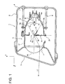
- FIG. 1 is a sectional view of a vehicular headlamp according to one or more embodiments of the present invention.
- FIG. 1 is a sectional view of a vehicular headlamp 1.
- the vehicular headlamp 1 includes a lamp body 2 having an opening portion that opens forward of the lamp, and a cover (outer cover) 3 made of a transparent resin and attached to the opening portion.
- the outer cover 3 is disposed to close the opening portion of the lamp body 2 from the front, and forms a lamp chamber 4 together with the lamp body 2.
- the direction of the arrow X shown in FIG. 1 is referred to as "forward”
- the direction of the arrow Y is referred to as "above”.
- a lamp unit 5 is disposed in the lamp chamber 4.
- the lamp unit 5 is supported by the lamp body 2 via an aiming mechanism 6.
- the direction of an optical axis Ax of the lamp unit 5 is adjustable by means of the aiming mechanism 6.
- the lamp unit 5 includes a projection lens 11 having the optical axis Ax extending in the vehicular longitudinal direction, a light source 12 disposed in rear of a rear focal point F2 of the projection lens 11, a reflector 13 that reflects light from the light source 12 forward and closer to the optical axis Ax, and a first shade 14 and a second shade 15 disposed between the light source 12 and the projection lens 11.
- the light source 12 is a light emitting portion (filament) of a filament bulb 16, for example.
- the filament bulb 16 is disposed with its long axis extending along the optical axis Ax.
- the filament bulb 16 is attached to the reflector 13 such that the light source 12 is positioned on the optical axis Ax extending in the vehicular longitudinal direction.
- a discharge bulb, an LED, an organic EL, etc. may also be employed as the light source 12.
- the reflector 13 includes a first reflective surface 13a and a second reflective surface 13b provided at a part of the outer periphery of the first reflective surface 13a.
- the first reflective surface 13a generally has the shape of a spheroid about the optical axis Ax.
- the first reflective surface 13a has a first focal point F1 generally matching the light source 12, and a second focal point generally matching the rear focal point F2 of the projection lens 11 to be discussed later. Consequently, the first reflective surface 13a reflects light from the light source 12 forward and closer to the optical axis Ax.
- the second reflective surface 13b is provided at the lower portion of the outer periphery of the first reflective surface 13a.
- the second reflective surface 13b reflects light from the light source 12 toward an OHS reflective surface 15c or a second opening 22 to be discussed later.
- the projection lens 11 is fixed to the front-end portion of the reflector 13 via a lens holder 17.
- the projection lens 11 is a planoconvex lens with a convex front-side surface and a flat rear-side surface. As discussed above, the projection lens 11 is disposed such that the rear focal point F2 generally matches the second focal point of the first reflective surface 13a of the reflector 13.
- the lens holder 17 is a tubular member that extends forward from the front-end opening portion of the reflector 13. The rear-end portion of the lens holder 17 is screwed to the reflector 13.
- the first shade 14 and the second shade 15 are formed by punching and bending a metal plate.
- the first shade 14 is fixed between the lens holder 17 and the reflector 13 to extend perpendicularly to the optical axis Ax.
- the first shade 14 is disposed at a position generally matching the second focal point of the first reflective surface 13a (rear focal point F2 of the projection lens 11) in the longitudinal direction of the optical axis Ax.
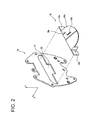
- FIG. 2 is an exploded perspective view of the first shade 14 and the second shade 15.
- FIG. 3 is a bottom view of the second shade 15.
- the first shade 14 is provided with a first opening 21 that is transversely long, and a second opening 22 that is narrower than the first opening 21. Light reflected from the reflector 13 passes through the first opening 21 and the second opening 22 to be radiated forward of the lamp via the projection lens 11.
- the second shade 15 includes a plate-like (tongue-shaped) body portion 15a that extends rearward and obliquely downward, and attachment portions 15b that extend toward both sides from the body portion 15a.
- the second shade 15 is fixed to the first shade 14 with the attachment portion 15b welded to the back surface of the first shade 14.
- a front-end portion 15e of the second shade 15 has a stepped shape in which the right side is higher than the left side as seen from the rear of the optical axis Ax.
- the second shade 15 is attached to the first shade 14 such that the front-end portion 15e extends along the boundary between the first opening 21 and the second opening 22 of the first shade 14.
- the front-end portion 15e is disposed at a position in the vicinity of the rear focal point F2 of the projection lens 11.
- the lower surface of the body portion 15a has been subjected to a reflective surface process to form the OHS reflective surface 15c which forms a part of an overhead sign distribution pattern (hereinafter abbreviated as "OHS distribution pattern") as discussed later.
- OHS distribution pattern an overhead sign distribution pattern
- a dark portion forming portion 15d to be discussed in detail later is provided in a part of the OHS reflective surface 15c.
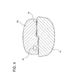
- FIG. 4 shows a light distribution pattern formed on a virtual vertical screen provided at a distance of about 25 m ahead of the lamp.
- the front-end portion 15e of the second shade 15 is positioned at the lower end of the first opening 21.
- the front-end portion 15e generally matches the rear focal point F2 of the projection lens 11. Therefore, when an image in the vicinity of the rear focal point F2 is projected ahead of the lamp in a vertically and laterally inverted manner by the projection lens 11, the outline of the front-end portion 15e forms a clear cut-off line CL positioned at the upper end of the low-beam distribution pattern PL.
- the front-end portion 15e of the second shade 15 has a stepped shape in which the right side is higher than the left side as seen from the rear. Therefore, as shown in FIG. 4 , the cut-off line CL is formed such that the low-beam distribution pattern PL has a stepped shape in which the left side is lower than the right side.
- the thus shaped low-beam distribution pattern PL is used in an area in which an oncoming vehicle passes on the left side of a host vehicle.
- FIG. 5 is a schematic view illustrating the paths of light in the vicinity of the first shade 14 and the second shade 15.
- a part of light L2 emitted from the light source 12 and reflected by the second reflective surface 13b of the reflector 13 directly passes through the second opening 22.
- another part of light L3 emitted from the light source 12 and reflected by the second reflective surface 13b of the reflector 13 is reflected by the OHS reflective surface 15c to pass through the second opening 22.
- a light beam L32 in FIG. 5 passes through a side of the dark portion forming portion 15d (back side with respect to the sheet surface corresponding to the section shown in FIG. 5 ) and is reflected by the OHS reflective surface 15c to pass through the second opening 22.
- the second opening 22 is provided below the first opening 21. Therefore, when the light L2 and L3 is projected by the projection lens 11, the OHS distribution pattern PO positioned above the low-beam distribution pattern PL is formed as shown in FIG. 4 . Consequently, a sign or the like positioned above and not illuminated with the low-beam distribution pattern PL can be illuminated with the OHS distribution pattern PO.
- the area of the second reflective surface 13b is set to be smaller than the area of the first reflective surface 13a. Consequently, the intensity of light passing through the second opening 22 is lower than the intensity of light passing through the first opening 21, and the illuminance of the OHS distribution pattern PO is lower than that of the low-beam distribution pattern PL.
- the area of the second reflective surface 13b is set to be smaller than the area of the first reflective surface 13a. Consequently, the intensity of light reflected by the second reflective surface 13b is lower than the intensity of light reflected by the first reflective surface 13a.
- the second focal point of the second reflective surface 13b is disposed at a position shifted downward with respect to the rear focal point F2 of the projection lens 11. Consequently, light reflected by the second reflective surface 13b is projected with a light source image blurred and enlarged.
- the OHS distribution pattern PO is formed ahead of the lamp as a blurred light distribution pattern with lower light intensity than that of the low-beam distribution pattern PL.
- the dark portion forming portion 15d which makes the eye point Px darker than around the eye point Px is formed on the OHS reflective surface 15c which forms a part of the OHS distribution pattern PO.
- the eye point Px corresponds to a region on the virtual screen discussed earlier in which the eyes of the driver of an oncoming vehicle is positioned.
- the dark portion forming portion 15d is provided at such a position that the light L3 would be reflected toward the eye point Px if the dark portion forming portion 15d were not provided but a reflective surface were provided in place of the dark portion forming portion 15d.
- the dark portion forming portion 15d reduces light directed toward the eye point Px to make the eye point Px darker than a portion of the OHS distribution pattern PO around the eye point Px.
- the dark portion forming portion 15d is a projecting portion formed on the OHS reflective surface 15c to project downward.
- the projecting portion can be easily formed by punching, for example.
- the dark portion forming portion 15d is provided at a position spaced rearward from the rear focal point of the projection lens 11 (position at a spacing distance L).
- light L31 incident on the dark portion forming portion 15d is diffused in the lateral direction of the lamp by the surface of the dark portion forming portion 15 so that most of the light incident on the dark portion forming portion 15d does not pass through the second opening 22. Consequently, it is possible to reduce light directed toward the eye point Px of the driver of an oncoming vehicle, thereby making the eye point Px darker than a portion of the OHS distribution pattern PO around the eye point Px.
- the dark portion forming portion 15d which makes the eye point Px darker than around the eye point Px is provided on the OHS reflective surface 15c of the second shade 15. This eliminates the need for a member that supports the dark portion forming portion 15d as in Patent Document 1. Thus, it is possible to provide the vehicular headlamp 1 composed of a smaller number of components and capable of forming the OHS distribution pattern PO.
- the dark portion forming portion 15d is formed integrally with the reflective surface 15c, which eliminates the need for a member that supports the dark portion forming portion 15d as in Patent Document 1.
- a shadow of a member that supports the dark portion forming portion is not projected forward of the lamp.
- only the low-beam distribution pattern PL and the OHS distribution pattern PO in which the eye point Px has been darkened are formed forward of the lamp. Consequently, it is possible to form a light distribution pattern that provides natural vision that does not give a user an uncomfortable feeling.
- the front end of the dark portion forming portion 15d is formed at a position spaced rearward from the rear focal point F2 of the projection lens 11. Therefore, a clear shadow of the outline of the dark portion forming portion 15d is not projected forward of the lamp. That is, the boundary between bright and dark portions is blurred in the light projected forward of the lamp, and therefore the dark portion at the eye point Px is not conspicuous unnaturally.
- the OHS distribution pattern PO which provides natural vision that does not give a user an uncomfortable feeling.
- the dark portion forming portion 15d can be formed at the same time as the second shade 15 is pressed, which facilitates processing.
- the vehicular headlamp 1 is not limited to the embodiment discussed earlier, and may be modified, improved, etc. as appropriate.
- the dark portion forming portion 15d is formed as a projecting portion in the embodiment discussed above, embodiments of the present invention is not limited thereto.
- the dark portion forming portion 15d may be formed as a recessed portion or a succession of recessed and projecting portions that is formed in the OHS reflective surface 15c.
- the dark portion forming portion 15d may be formed by performing a graining process or a surface roughening process on a part of the OHS reflective surface 15c.
- the eye point Px is darkened with the dark portion forming portion 15d diffusing light in directions other than the direction of the eye point Px. If light is diffused by the dark portion forming portion 15d to darken the eye point Px, it is easy to form the OHS distribution pattern PO which provides natural vision in which the light intensity is gradually lowered toward around the eye point Px.
- the dark portion forming portion 15d may be formed by applying or printing a paint with high absorbance, or affixing a laser mark to burn a part of the OHS reflective surface 15c.
- the dark portion forming portion 15d absorbs light to darken the eye point.
- the dark portion forming portion 15d can be formed easily.
- the dark portion forming portion 15d is formed in an elongated shape to extend in the longitudinal direction in accordance with the shape of the filament extending in the longitudinal direction of the filament bulb 16. This makes it possible to efficiently diffuse light directed from the light source 12 toward the eye point Px, and to efficiently darken the eye point Px.
- the dark portion forming portion 15d may be shaped variously in accordance with the shape of the light source 12. For example, in the case where an LED array in which a plurality of LEDs are arranged in the transverse direction is used as the light source, the dark portion forming portion 15d may also be shaped to extend in the transverse direction.
- the vehicular headlamp 1 can form a low-beam distribution pattern for use in an area in which an oncoming vehicle passes on the left side of the host vehicle.
- embodiments of the present invention is not limited thereto. It is possible to form the vehicular headlamp 1 which forms a variety of light distribution patterns as the forward light distribution pattern, such as a low-beam distribution pattern for use in an area in which an oncoming vehicle passes on the right side of the host vehicle, by changing the shape of the front-end portion 15e of the second shade 15.
- the vehicular headlamp 1 forms the low-beam distribution pattern PL and the OHS distribution pattern PO as the forward light distribution pattern.
- the present invention is not limited thereto.
- one or more embodiments of the present invention may be applied to a vehicular headlamp that forms a fog lamp distribution pattern having a cut-off line and the OHS distribution pattern PO as the forward light distribution pattern.
Landscapes
- Engineering & Computer Science (AREA)
- General Engineering & Computer Science (AREA)
- Non-Portable Lighting Devices Or Systems Thereof (AREA)
Abstract

Description
- The present invention relates to a vehicular headlamp.
- Patent Document 1 describes an example of a vehicular headlamp capable of forming an overhead sign distribution pattern that illuminates a sign positioned above and ahead of a vehicle (overhead sign) etc. during travel of the vehicle.
- Patent Document 1: Japanese Patent No.
4579154 - In such an overhead sign distribution pattern, the illuminance is reduced in a certain region called "eye point" in order not to radiate bright light to the eyes of a driver of an oncoming vehicle (in order to prevent giving glare). In the vehicular headlamp described in Patent Document 1, a part of light to reach the eye point is blocked by the distal-end portion of an additional shielding portion to reduce the illuminance at the eye point.
- The distal-end portion of the additional shielding portion is disposed in the vicinity of the rear focal point of a projection lens, and therefore the outline of the additional shielding portion may be clearly projected forward of the lamp to form an unnatural light distribution pattern. In addition, a dark portion formed by a member that supports the distal-end portion of the additional shielding portion blocking light is also projected forward of the lamp, which may also form an unnatural light distribution pattern. Further, the additional shielding portion is formed separately from a shade that forms a low-beam distribution pattern and a contrast boundary forming plate, which increases the number of components of the lamp.
- One or more embodiments of the present invention provides a vehicular headlamp that is composed of a small number of components and that enables an overhead sign to be seen naturally.
A vehicular headlamp according to one or more of the present invention comprises a projection lens; a light source disposed in rear of a rear focal point of the projection lens; and a reflector that reflects light from the light source forward, the vehicular headlamp forming a forward light distribution pattern, characterized in that the vehicular headlamp includes a plate-like shade having a front-end portion positioned in the vicinity of the rear focal point of the projection lens to form a cut-off line of the forward light distribution pattern, the shade extending rearward and obliquely downward from the front-end portion; an overhead sign reflective surface is provided on a lower surface of the shade, the overhead sign reflective surface reflecting light from the reflector toward the projection lens to form a part of an overhead sign distribution pattern; and a dark portion forming portion is formed on the overhead sign reflective surface, the dark portion forming portion making a portion of the overhead sign distribution pattern corresponding to an eye point of a driver of an oncoming vehicle darker than around the eye point. - In a vehicular headlamp according to one or more embodiments of the present invention, the dark portion forming portion may be formed at a position spaced rearward from the rear focal point of the projection lens.
- In a vehicular headlamp according to one or more embodiments of the present invention, the dark portion forming portion may be a projecting portion that projects downward.
- In a vehicular headlamp according to one or more embodiments of the present invention, the dark portion forming portion may be formed in an elongated shape to extend in a longitudinal direction.
- In a vehicular headlamp according to one or more embodiments of the present invention, the dark portion forming portion may diffuse or absorb light from the reflector to make the eye point darker than around the eye point.
- According to one or more embodiments of the present invention, the dark portion forming portion which darkens the eye point of a driver of an oncoming vehicle is formed on the overhead sign reflective surface which forms an overhead sign distribution pattern. This makes it possible to provide a vehicular headlamp composed of a small number of components and capable of forming an overhead sign distribution pattern in which the eye point has been darkened. In addition, a dark portion due to a member other than the dark portion forming portion is not projected on the overhead sign distribution pattern. This makes it possible to form an overhead sign distribution pattern that provides natural vision that does not give an uncomfortable feeling.
-
FIG. 1 is a sectional view of a vehicular headlamp according to one or more embodiments of the present invention. -
FIG. 2 is an exploded perspective view of a first shade and a second shade. -
FIG. 3 is a bottom view of the second shade. -
FIG. 4 shows a forward light distribution pattern formed by the vehicular headlamp. -
FIG. 5 is a schematic view illustrating the paths of light in the vicinity of the first shade and the second shade. - A vehicular headlamp according to embodiments of the present invention will be described below with reference to the accompanying drawings. In embodiments of the invention, numerous specific details are set forth in order to provide a more thorough understanding of the invention. However, it will be apparent to one of ordinary skill in the art that the invention may be practiced without these specific details. In other instances, well-known features have not been described in detail to avoid obscuring the invention.
-
FIG. 1 is a sectional view of a vehicular headlamp 1. The vehicular headlamp 1 includes alamp body 2 having an opening portion that opens forward of the lamp, and a cover (outer cover) 3 made of a transparent resin and attached to the opening portion. Theouter cover 3 is disposed to close the opening portion of thelamp body 2 from the front, and forms a lamp chamber 4 together with thelamp body 2. In the following description, the direction of the arrow X shown inFIG. 1 is referred to as "forward", and the direction of the arrow Y is referred to as "above". - A
lamp unit 5 is disposed in the lamp chamber 4. Thelamp unit 5 is supported by thelamp body 2 via an aiming mechanism 6. The direction of an optical axis Ax of thelamp unit 5 is adjustable by means of the aiming mechanism 6. - The
lamp unit 5 includes a projection lens 11 having the optical axis Ax extending in the vehicular longitudinal direction, alight source 12 disposed in rear of a rear focal point F2 of the projection lens 11, areflector 13 that reflects light from thelight source 12 forward and closer to the optical axis Ax, and afirst shade 14 and asecond shade 15 disposed between thelight source 12 and the projection lens 11. - The
light source 12 is a light emitting portion (filament) of afilament bulb 16, for example. In the embodiment, thefilament bulb 16 is disposed with its long axis extending along the optical axis Ax. In addition, thefilament bulb 16 is attached to thereflector 13 such that thelight source 12 is positioned on the optical axis Ax extending in the vehicular longitudinal direction. A discharge bulb, an LED, an organic EL, etc. may also be employed as thelight source 12. - The
reflector 13 includes a firstreflective surface 13a and a secondreflective surface 13b provided at a part of the outer periphery of the firstreflective surface 13a. The firstreflective surface 13a generally has the shape of a spheroid about the optical axis Ax. The firstreflective surface 13a has a first focal point F1 generally matching thelight source 12, and a second focal point generally matching the rear focal point F2 of the projection lens 11 to be discussed later. Consequently, the firstreflective surface 13a reflects light from thelight source 12 forward and closer to the optical axis Ax. - The second
reflective surface 13b is provided at the lower portion of the outer periphery of the firstreflective surface 13a. The secondreflective surface 13b reflects light from thelight source 12 toward an OHSreflective surface 15c or asecond opening 22 to be discussed later. - The projection lens 11 is fixed to the front-end portion of the
reflector 13 via alens holder 17. The projection lens 11 is a planoconvex lens with a convex front-side surface and a flat rear-side surface. As discussed above, the projection lens 11 is disposed such that the rear focal point F2 generally matches the second focal point of the firstreflective surface 13a of thereflector 13. - The
lens holder 17 is a tubular member that extends forward from the front-end opening portion of thereflector 13. The rear-end portion of thelens holder 17 is screwed to thereflector 13. - The
first shade 14 and thesecond shade 15 are formed by punching and bending a metal plate. Thefirst shade 14 is fixed between thelens holder 17 and thereflector 13 to extend perpendicularly to the optical axis Ax. In addition, thefirst shade 14 is disposed at a position generally matching the second focal point of the firstreflective surface 13a (rear focal point F2 of the projection lens 11) in the longitudinal direction of the optical axis Ax. -
FIG. 2 is an exploded perspective view of thefirst shade 14 and thesecond shade 15.FIG. 3 is a bottom view of thesecond shade 15. As shown inFIG. 2 , thefirst shade 14 is provided with afirst opening 21 that is transversely long, and a second opening 22 that is narrower than thefirst opening 21. Light reflected from thereflector 13 passes through the first opening 21 and the second opening 22 to be radiated forward of the lamp via the projection lens 11. - The
second shade 15 includes a plate-like (tongue-shaped)body portion 15a that extends rearward and obliquely downward, andattachment portions 15b that extend toward both sides from thebody portion 15a. Thesecond shade 15 is fixed to thefirst shade 14 with theattachment portion 15b welded to the back surface of thefirst shade 14. - A front-
end portion 15e of thesecond shade 15 has a stepped shape in which the right side is higher than the left side as seen from the rear of the optical axis Ax. Thesecond shade 15 is attached to thefirst shade 14 such that the front-end portion 15e extends along the boundary between thefirst opening 21 and thesecond opening 22 of thefirst shade 14. In addition, the front-end portion 15e is disposed at a position in the vicinity of the rear focal point F2 of the projection lens 11. - The lower surface of the
body portion 15a has been subjected to a reflective surface process to form the OHSreflective surface 15c which forms a part of an overhead sign distribution pattern (hereinafter abbreviated as "OHS distribution pattern") as discussed later. In addition, a darkportion forming portion 15d to be discussed in detail later is provided in a part of the OHSreflective surface 15c. - Next, a low-beam distribution pattern PL serving as a forward light distribution pattern will be described. As shown in
FIG. 1 , light L1 emitted from thelight source 12 and reflected by the firstreflective surface 13a of thereflector 13 passes through thefirst opening 21 of thefirst shade 14 to form the low-beam distribution pattern PL shown inFIG. 4. FIG. 4 shows a light distribution pattern formed on a virtual vertical screen provided at a distance of about 25 m ahead of the lamp. - The front-
end portion 15e of thesecond shade 15 is positioned at the lower end of thefirst opening 21. In addition, the front-end portion 15e generally matches the rear focal point F2 of the projection lens 11. Therefore, when an image in the vicinity of the rear focal point F2 is projected ahead of the lamp in a vertically and laterally inverted manner by the projection lens 11, the outline of the front-end portion 15e forms a clear cut-off line CL positioned at the upper end of the low-beam distribution pattern PL. - In the embodiment, as discussed above, the front-
end portion 15e of thesecond shade 15 has a stepped shape in which the right side is higher than the left side as seen from the rear. Therefore, as shown inFIG. 4 , the cut-off line CL is formed such that the low-beam distribution pattern PL has a stepped shape in which the left side is lower than the right side. The thus shaped low-beam distribution pattern PL is used in an area in which an oncoming vehicle passes on the left side of a host vehicle. - Next, an OHS distribution pattern PO will be described with reference to
FIG. 5. FIG. 5 is a schematic view illustrating the paths of light in the vicinity of thefirst shade 14 and thesecond shade 15. As shown inFIG. 5 , a part of light L2 emitted from thelight source 12 and reflected by the secondreflective surface 13b of thereflector 13 directly passes through thesecond opening 22. In addition, another part of light L3 emitted from thelight source 12 and reflected by the secondreflective surface 13b of thereflector 13 is reflected by the OHSreflective surface 15c to pass through thesecond opening 22. A light beam L32 inFIG. 5 passes through a side of the darkportion forming portion 15d (back side with respect to the sheet surface corresponding to the section shown inFIG. 5 ) and is reflected by the OHSreflective surface 15c to pass through thesecond opening 22. - The
second opening 22 is provided below thefirst opening 21. Therefore, when the light L2 and L3 is projected by the projection lens 11, the OHS distribution pattern PO positioned above the low-beam distribution pattern PL is formed as shown inFIG. 4 . Consequently, a sign or the like positioned above and not illuminated with the low-beam distribution pattern PL can be illuminated with the OHS distribution pattern PO. - The area of the second
reflective surface 13b is set to be smaller than the area of the firstreflective surface 13a. Consequently, the intensity of light passing through thesecond opening 22 is lower than the intensity of light passing through thefirst opening 21, and the illuminance of the OHS distribution pattern PO is lower than that of the low-beam distribution pattern PL. - Again, the area of the second
reflective surface 13b is set to be smaller than the area of the firstreflective surface 13a. Consequently, the intensity of light reflected by the secondreflective surface 13b is lower than the intensity of light reflected by the firstreflective surface 13a. In addition, the second focal point of the secondreflective surface 13b is disposed at a position shifted downward with respect to the rear focal point F2 of the projection lens 11. Consequently, light reflected by the secondreflective surface 13b is projected with a light source image blurred and enlarged. Thus, the OHS distribution pattern PO is formed ahead of the lamp as a blurred light distribution pattern with lower light intensity than that of the low-beam distribution pattern PL. - According to one or more embodiments of the present invention, in the thus formed OHS distribution pattern PO, only extremely weak light is radiated to an eye point Px in order not to give glare to the driver of an oncoming vehicle. Therefore, in the vehicular headlamp 1 according to the embodiment, the dark
portion forming portion 15d which makes the eye point Px darker than around the eye point Px is formed on the OHSreflective surface 15c which forms a part of the OHS distribution pattern PO. The eye point Px corresponds to a region on the virtual screen discussed earlier in which the eyes of the driver of an oncoming vehicle is positioned. - The dark
portion forming portion 15d is provided at such a position that the light L3 would be reflected toward the eye point Px if the darkportion forming portion 15d were not provided but a reflective surface were provided in place of the darkportion forming portion 15d. The darkportion forming portion 15d reduces light directed toward the eye point Px to make the eye point Px darker than a portion of the OHS distribution pattern PO around the eye point Px. - In the embodiment, as shown in
FIG. 5 , the darkportion forming portion 15d is a projecting portion formed on the OHSreflective surface 15c to project downward. The projecting portion can be easily formed by punching, for example. In addition, according to one or more embodiments of the present invention, as shown inFIG. 2 , the darkportion forming portion 15d is provided at a position spaced rearward from the rear focal point of the projection lens 11 (position at a spacing distance L). - Of the light L3 incident on the OHS
reflective surface 15c, light L31 incident on the darkportion forming portion 15d is diffused in the lateral direction of the lamp by the surface of the darkportion forming portion 15 so that most of the light incident on the darkportion forming portion 15d does not pass through thesecond opening 22. Consequently, it is possible to reduce light directed toward the eye point Px of the driver of an oncoming vehicle, thereby making the eye point Px darker than a portion of the OHS distribution pattern PO around the eye point Px. - In the vehicular headlamp 1 according to the embodiment described above, the dark
portion forming portion 15d which makes the eye point Px darker than around the eye point Px is provided on the OHSreflective surface 15c of thesecond shade 15. This eliminates the need for a member that supports the darkportion forming portion 15d as in Patent Document 1. Thus, it is possible to provide the vehicular headlamp 1 composed of a smaller number of components and capable of forming the OHS distribution pattern PO. - In addition, the dark
portion forming portion 15d is formed integrally with thereflective surface 15c, which eliminates the need for a member that supports the darkportion forming portion 15d as in Patent Document 1. Thus, a shadow of a member that supports the dark portion forming portion is not projected forward of the lamp. Thus, only the low-beam distribution pattern PL and the OHS distribution pattern PO in which the eye point Px has been darkened are formed forward of the lamp. Consequently, it is possible to form a light distribution pattern that provides natural vision that does not give a user an uncomfortable feeling. - In addition, the front end of the dark
portion forming portion 15d is formed at a position spaced rearward from the rear focal point F2 of the projection lens 11. Therefore, a clear shadow of the outline of the darkportion forming portion 15d is not projected forward of the lamp. That is, the boundary between bright and dark portions is blurred in the light projected forward of the lamp, and therefore the dark portion at the eye point Px is not conspicuous unnaturally. Thus, it is possible to form the OHS distribution pattern PO which provides natural vision that does not give a user an uncomfortable feeling. - In the case where a projecting portion is formed as the dark
portion forming portion 15d as in the embodiment, the darkportion forming portion 15d can be formed at the same time as thesecond shade 15 is pressed, which facilitates processing. Thus, it is possible to form the darkportion forming portion 15d without preparing a special process, and thus to provide the vehicular headlamp 1 capable of forming the OHS distribution pattern PO at a low cost. - The vehicular headlamp 1 is not limited to the embodiment discussed earlier, and may be modified, improved, etc. as appropriate.
- For example, although the dark
portion forming portion 15d is formed as a projecting portion in the embodiment discussed above, embodiments of the present invention is not limited thereto. For example, the darkportion forming portion 15d may be formed as a recessed portion or a succession of recessed and projecting portions that is formed in the OHSreflective surface 15c. Alternatively, the darkportion forming portion 15d may be formed by performing a graining process or a surface roughening process on a part of the OHSreflective surface 15c. - In such cases, the eye point Px is darkened with the dark
portion forming portion 15d diffusing light in directions other than the direction of the eye point Px. If light is diffused by the darkportion forming portion 15d to darken the eye point Px, it is easy to form the OHS distribution pattern PO which provides natural vision in which the light intensity is gradually lowered toward around the eye point Px. - Alternatively, the dark
portion forming portion 15d may be formed by applying or printing a paint with high absorbance, or affixing a laser mark to burn a part of the OHSreflective surface 15c. In this case, the darkportion forming portion 15d absorbs light to darken the eye point. Also in this case, the darkportion forming portion 15d can be formed easily. - In the embodiment discussed above, the dark
portion forming portion 15d is formed in an elongated shape to extend in the longitudinal direction in accordance with the shape of the filament extending in the longitudinal direction of thefilament bulb 16. This makes it possible to efficiently diffuse light directed from thelight source 12 toward the eye point Px, and to efficiently darken the eye point Px. The darkportion forming portion 15d may be shaped variously in accordance with the shape of thelight source 12. For example, in the case where an LED array in which a plurality of LEDs are arranged in the transverse direction is used as the light source, the darkportion forming portion 15d may also be shaped to extend in the transverse direction. - As discussed above, the vehicular headlamp 1 can form a low-beam distribution pattern for use in an area in which an oncoming vehicle passes on the left side of the host vehicle. However, embodiments of the present invention is not limited thereto. It is possible to form the vehicular headlamp 1 which forms a variety of light distribution patterns as the forward light distribution pattern, such as a low-beam distribution pattern for use in an area in which an oncoming vehicle passes on the right side of the host vehicle, by changing the shape of the front-
end portion 15e of thesecond shade 15. - As discussed above, the vehicular headlamp 1 forms the low-beam distribution pattern PL and the OHS distribution pattern PO as the forward light distribution pattern. However, the present invention is not limited thereto. For example, one or more embodiments of the present invention may be applied to a vehicular headlamp that forms a fog lamp distribution pattern having a cut-off line and the OHS distribution pattern PO as the forward light distribution pattern.
- While the invention has been described with respect to a limited number of embodiments, those skilled in the art, having benefit of this disclosure, will appreciate that other embodiments can be devised which do not depart from the scope of the invention as disclosed herein. Accordingly, the scope of the invention should be limited only by the attached claims.
- Description of the Reference Numerals
- 1
- VEHICULAR HEADLAMP
- 2
- LAMP BODY
- 3
- OUTER COVER
- 4
- LAMP CHAMBER
- 5
- LAMP UNIT
- 11
- PROJECTION LENS
- 12
- LIGHT SOURCE
- 13
- REFLECTOR
- 13a
- FIRST REFLECTIVE SURFACE
- 13b
- SECOND REFLECTIVE SURFACE
- 14
- FIRST SHADE
- 15
- SECOND SHADE
- 15a
- BODY PORTION
- 15b
- ATTACHMENT PORTION
- 15c
- OHS REFLECTIVE SURFACE
- 15d
- DARK PORTION FORMING PORTION
- 15e
- FRONT-END PORTION
- 21
- FIRST OPENING
- 22
- SECOND OPENING
Claims (5)
- A vehicular headlamp comprising:a projection lens;a light source disposed behind a rear focal point of the projection lens; anda reflector that reflects light from the light source forward,wherein the vehicular headlamp forms a forward light distribution pattern,wherein the vehicular headlamp includes a plate-like shade having a front-end portion positioned in the vicinity of the rear focal point of the projection lens to form a cut-off line of the forward light distribution pattern,wherein the shade extends rearward and obliquely downward from the front-end portion,wherein an overhead sign reflective surface is provided on a lower surface of the shade,wherein the overhead sign reflective surface reflects light from the reflector toward the projection lens to form a part of an overhead sign distribution pattern,wherein a dark portion forming portion is formed on the overhead sign reflective surface, andwherein the dark portion forming portion forms a first portion of the overhead sign distribution pattern corresponding to an eye point of a driver of an oncoming vehicle to be darker than a second portion around the eye point.
- The vehicle headlamp according to claim 1, wherein the dark portion forming portion is formed at a position spaced rearward from the rear focal point of the projection lens.
- The vehicular headlamp according to claim 1 to 2, wherein the dark portion forming portion is a projecting portion that projects downward.
- The vehicular headlamp according to claim 1 to 3, wherein the dark portion forming portion is formed in an elongated shape to extend in a longitudinal direction.
- The vehicular headlamp according to claim 1 to 4, wherein the dark portion forming portion diffuses or absorbs light from the reflector to make the first portion darker than the second portion.
Applications Claiming Priority (1)
| Application Number | Priority Date | Filing Date | Title |
|---|---|---|---|
| JP2012169252A JP5977111B2 (en) | 2012-07-31 | 2012-07-31 | Vehicle headlamp |
Publications (2)
| Publication Number | Publication Date |
|---|---|
| EP2693110A2 true EP2693110A2 (en) | 2014-02-05 |
| EP2693110A3 EP2693110A3 (en) | 2015-12-23 |
Family
ID=48793100
Family Applications (1)
| Application Number | Title | Priority Date | Filing Date |
|---|---|---|---|
| EP13176939.0A Withdrawn EP2693110A3 (en) | 2012-07-31 | 2013-07-17 | Vehicular headlamp |
Country Status (4)
| Country | Link |
|---|---|
| US (1) | US9028118B2 (en) |
| EP (1) | EP2693110A3 (en) |
| JP (1) | JP5977111B2 (en) |
| CN (1) | CN103574462A (en) |
Families Citing this family (6)
| Publication number | Priority date | Publication date | Assignee | Title |
|---|---|---|---|---|
| JP6595258B2 (en) * | 2015-08-26 | 2019-10-23 | 株式会社小糸製作所 | Lamp |
| CN105240765A (en) * | 2015-10-30 | 2016-01-13 | 江苏亿诺车辆部件有限公司 | Far and near light switchable type lens set |
| JP2018073775A (en) * | 2016-11-04 | 2018-05-10 | 市光工業株式会社 | Vehicular lamp |
| JP6885268B2 (en) * | 2017-09-04 | 2021-06-09 | トヨタ自動車株式会社 | Vehicle lighting device |
| TWI651489B (en) * | 2018-01-29 | 2019-02-21 | 誠益光電科技股份有限公司 | Smart headlight |
| US11048454B2 (en) | 2018-03-07 | 2021-06-29 | Zebra Technologies Corporation | Method and apparatus to protect sensitive information on media processing devices |
Citations (1)
| Publication number | Priority date | Publication date | Assignee | Title |
|---|---|---|---|---|
| US20070147062A1 (en) * | 2005-12-28 | 2007-06-28 | Koito Manufacturing Co., Ltd. | Vehicle headlamp |
Family Cites Families (8)
| Publication number | Priority date | Publication date | Assignee | Title |
|---|---|---|---|---|
| JP3964089B2 (en) * | 2000-01-12 | 2007-08-22 | 株式会社小糸製作所 | Vehicle headlamp |
| AT412992B (en) * | 2000-11-07 | 2005-09-26 | Zizala Lichtsysteme Gmbh | VEHICLE HEADLIGHTS |
| JP3798723B2 (en) * | 2002-04-08 | 2006-07-19 | 株式会社小糸製作所 | Vehicle headlamp |
| JP4669434B2 (en) * | 2006-04-24 | 2011-04-13 | 株式会社小糸製作所 | Vehicle headlamp |
| JP4781951B2 (en) * | 2006-09-19 | 2011-09-28 | 株式会社小糸製作所 | Vehicle lamp unit and vehicle lamp |
| JP4811429B2 (en) * | 2008-05-07 | 2011-11-09 | 市光工業株式会社 | Projector type headlamp |
| JP5524470B2 (en) * | 2008-11-12 | 2014-06-18 | 株式会社小糸製作所 | Vehicle lamp unit and vehicle lamp |
| JP5535663B2 (en) * | 2010-01-14 | 2014-07-02 | 株式会社小糸製作所 | Vehicle headlamp |
-
2012
- 2012-07-31 JP JP2012169252A patent/JP5977111B2/en not_active Expired - Fee Related
-
2013
- 2013-07-17 EP EP13176939.0A patent/EP2693110A3/en not_active Withdrawn
- 2013-07-30 US US13/954,264 patent/US9028118B2/en not_active Expired - Fee Related
- 2013-07-31 CN CN201310328984.1A patent/CN103574462A/en active Pending
Patent Citations (2)
| Publication number | Priority date | Publication date | Assignee | Title |
|---|---|---|---|---|
| US20070147062A1 (en) * | 2005-12-28 | 2007-06-28 | Koito Manufacturing Co., Ltd. | Vehicle headlamp |
| JP4579154B2 (en) | 2005-12-28 | 2010-11-10 | 株式会社小糸製作所 | Vehicle headlamp |
Also Published As
| Publication number | Publication date |
|---|---|
| US20140036524A1 (en) | 2014-02-06 |
| JP5977111B2 (en) | 2016-08-24 |
| US9028118B2 (en) | 2015-05-12 |
| CN103574462A (en) | 2014-02-12 |
| EP2693110A3 (en) | 2015-12-23 |
| JP2014029772A (en) | 2014-02-13 |
Similar Documents
| Publication | Publication Date | Title |
|---|---|---|
| US9644811B2 (en) | Vehicular headlamp | |
| EP2299166B1 (en) | Lamp unit for vehicle headlamp | |
| JP4205048B2 (en) | Vehicle headlamp | |
| US8523417B2 (en) | Vehicular headlamp | |
| KR100815039B1 (en) | Lamp unit of vehicular headlamp | |
| JP6246007B2 (en) | Vehicle lighting | |
| US9028118B2 (en) | Vehicular headlamp | |
| EP2216590A1 (en) | Vehicle lamp | |
| CN102374468B (en) | Vehicle headlamp | |
| EP2028411A2 (en) | Vehicle cornering lamp | |
| EP2407710A2 (en) | Vehicle lamp | |
| JP6030932B2 (en) | Vehicle headlamp | |
| JP2001195910A (en) | Vehicle headlights | |
| JP4781951B2 (en) | Vehicle lamp unit and vehicle lamp | |
| JP2010118203A (en) | Vehicular lighting fixture unit and vehicular lighting fixture | |
| US20120140503A1 (en) | Head Lamp for Vehicle | |
| JP5686240B2 (en) | Vehicle lighting | |
| JP2018041589A (en) | Vehicular headlamp | |
| US7350946B2 (en) | Vehicle headlamp | |
| US20030185017A1 (en) | Projection-type vehicular headlamp | |
| US6837601B2 (en) | Lighting system for vehicle | |
| JP2021034339A (en) | Vehicular headlight | |
| EP2226555A2 (en) | Vehicular headlamp | |
| JP3145958B2 (en) | Vehicle headlights | |
| JP2015146270A (en) | Vehicle lighting |
Legal Events
| Date | Code | Title | Description |
|---|---|---|---|
| 17P | Request for examination filed |
Effective date: 20130717 |
|
| AK | Designated contracting states |
Kind code of ref document: A2 Designated state(s): AL AT BE BG CH CY CZ DE DK EE ES FI FR GB GR HR HU IE IS IT LI LT LU LV MC MK MT NL NO PL PT RO RS SE SI SK SM TR |
|
| AX | Request for extension of the european patent |
Extension state: BA ME |
|
| PUAI | Public reference made under article 153(3) epc to a published international application that has entered the european phase |
Free format text: ORIGINAL CODE: 0009012 |
|
| PUAL | Search report despatched |
Free format text: ORIGINAL CODE: 0009013 |
|
| AK | Designated contracting states |
Kind code of ref document: A3 Designated state(s): AL AT BE BG CH CY CZ DE DK EE ES FI FR GB GR HR HU IE IS IT LI LT LU LV MC MK MT NL NO PL PT RO RS SE SI SK SM TR |
|
| AX | Request for extension of the european patent |
Extension state: BA ME |
|
| RIC1 | Information provided on ipc code assigned before grant |
Ipc: F21S 8/10 20060101AFI20151119BHEP Ipc: F21S 8/12 20060101ALI20151119BHEP Ipc: F21V 11/00 20150101ALI20151119BHEP |
|
| 17Q | First examination report despatched |
Effective date: 20191025 |
|
| GRAP | Despatch of communication of intention to grant a patent |
Free format text: ORIGINAL CODE: EPIDOSNIGR1 |
|
| RIC1 | Information provided on ipc code assigned before grant |
Ipc: F21V 11/00 20150101ALI20200220BHEP Ipc: F21S 41/32 20180101AFI20200220BHEP Ipc: F21S 41/33 20180101ALI20200220BHEP |
|
| INTG | Intention to grant announced |
Effective date: 20200318 |
|
| STAA | Information on the status of an ep patent application or granted ep patent |
Free format text: STATUS: THE APPLICATION IS DEEMED TO BE WITHDRAWN |
|
| 18D | Application deemed to be withdrawn |
Effective date: 20200729 |