EP2692837A1 - Method of molding gas hydrate pellet - Google Patents
Method of molding gas hydrate pellet Download PDFInfo
- Publication number
- EP2692837A1 EP2692837A1 EP12765558.7A EP12765558A EP2692837A1 EP 2692837 A1 EP2692837 A1 EP 2692837A1 EP 12765558 A EP12765558 A EP 12765558A EP 2692837 A1 EP2692837 A1 EP 2692837A1
- Authority
- EP
- European Patent Office
- Prior art keywords
- gas hydrate
- compression
- pellet
- slurry
- plunger
- Prior art date
- Legal status (The legal status is an assumption and is not a legal conclusion. Google has not performed a legal analysis and makes no representation as to the accuracy of the status listed.)
- Granted
Links
Images



Classifications
-
- C—CHEMISTRY; METALLURGY
- C10—PETROLEUM, GAS OR COKE INDUSTRIES; TECHNICAL GASES CONTAINING CARBON MONOXIDE; FUELS; LUBRICANTS; PEAT
- C10L—FUELS NOT OTHERWISE PROVIDED FOR; NATURAL GAS; SYNTHETIC NATURAL GAS OBTAINED BY PROCESSES NOT COVERED BY SUBCLASSES C10G OR C10K; LIQUIFIED PETROLEUM GAS; USE OF ADDITIVES TO FUELS OR FIRES; FIRE-LIGHTERS
- C10L3/00—Gaseous fuels; Natural gas; Synthetic natural gas obtained by processes not covered by subclass C10G, C10K; Liquefied petroleum gas
- C10L3/06—Natural gas; Synthetic natural gas obtained by processes not covered by C10G, C10K3/02 or C10K3/04
-
- B—PERFORMING OPERATIONS; TRANSPORTING
- B01—PHYSICAL OR CHEMICAL PROCESSES OR APPARATUS IN GENERAL
- B01J—CHEMICAL OR PHYSICAL PROCESSES, e.g. CATALYSIS OR COLLOID CHEMISTRY; THEIR RELEVANT APPARATUS
- B01J2/00—Processes or devices for granulating materials, e.g. fertilisers in general; Rendering particulate materials free flowing in general, e.g. making them hydrophobic
- B01J2/22—Processes or devices for granulating materials, e.g. fertilisers in general; Rendering particulate materials free flowing in general, e.g. making them hydrophobic by pressing in moulds or between rollers
-
- B—PERFORMING OPERATIONS; TRANSPORTING
- B30—PRESSES
- B30B—PRESSES IN GENERAL
- B30B9/00—Presses specially adapted for particular purposes
- B30B9/02—Presses specially adapted for particular purposes for squeezing-out liquid from liquid-containing material, e.g. juice from fruits, oil from oil-containing material
- B30B9/04—Presses specially adapted for particular purposes for squeezing-out liquid from liquid-containing material, e.g. juice from fruits, oil from oil-containing material using press rams
-
- B—PERFORMING OPERATIONS; TRANSPORTING
- B30—PRESSES
- B30B—PRESSES IN GENERAL
- B30B9/00—Presses specially adapted for particular purposes
- B30B9/02—Presses specially adapted for particular purposes for squeezing-out liquid from liquid-containing material, e.g. juice from fruits, oil from oil-containing material
- B30B9/04—Presses specially adapted for particular purposes for squeezing-out liquid from liquid-containing material, e.g. juice from fruits, oil from oil-containing material using press rams
- B30B9/06—Presses specially adapted for particular purposes for squeezing-out liquid from liquid-containing material, e.g. juice from fruits, oil from oil-containing material using press rams co-operating with permeable casings or strainers
- B30B9/067—Presses specially adapted for particular purposes for squeezing-out liquid from liquid-containing material, e.g. juice from fruits, oil from oil-containing material using press rams co-operating with permeable casings or strainers with a retractable abutment member closing one end of the press chamber
-
- C—CHEMISTRY; METALLURGY
- C10—PETROLEUM, GAS OR COKE INDUSTRIES; TECHNICAL GASES CONTAINING CARBON MONOXIDE; FUELS; LUBRICANTS; PEAT
- C10L—FUELS NOT OTHERWISE PROVIDED FOR; NATURAL GAS; SYNTHETIC NATURAL GAS OBTAINED BY PROCESSES NOT COVERED BY SUBCLASSES C10G OR C10K; LIQUIFIED PETROLEUM GAS; USE OF ADDITIVES TO FUELS OR FIRES; FIRE-LIGHTERS
- C10L3/00—Gaseous fuels; Natural gas; Synthetic natural gas obtained by processes not covered by subclass C10G, C10K; Liquefied petroleum gas
- C10L3/06—Natural gas; Synthetic natural gas obtained by processes not covered by C10G, C10K3/02 or C10K3/04
- C10L3/10—Working-up natural gas or synthetic natural gas
-
- C—CHEMISTRY; METALLURGY
- C10—PETROLEUM, GAS OR COKE INDUSTRIES; TECHNICAL GASES CONTAINING CARBON MONOXIDE; FUELS; LUBRICANTS; PEAT
- C10L—FUELS NOT OTHERWISE PROVIDED FOR; NATURAL GAS; SYNTHETIC NATURAL GAS OBTAINED BY PROCESSES NOT COVERED BY SUBCLASSES C10G OR C10K; LIQUIFIED PETROLEUM GAS; USE OF ADDITIVES TO FUELS OR FIRES; FIRE-LIGHTERS
- C10L3/00—Gaseous fuels; Natural gas; Synthetic natural gas obtained by processes not covered by subclass C10G, C10K; Liquefied petroleum gas
- C10L3/06—Natural gas; Synthetic natural gas obtained by processes not covered by C10G, C10K3/02 or C10K3/04
- C10L3/10—Working-up natural gas or synthetic natural gas
- C10L3/108—Production of gas hydrates
-
- C—CHEMISTRY; METALLURGY
- C10—PETROLEUM, GAS OR COKE INDUSTRIES; TECHNICAL GASES CONTAINING CARBON MONOXIDE; FUELS; LUBRICANTS; PEAT
- C10L—FUELS NOT OTHERWISE PROVIDED FOR; NATURAL GAS; SYNTHETIC NATURAL GAS OBTAINED BY PROCESSES NOT COVERED BY SUBCLASSES C10G OR C10K; LIQUIFIED PETROLEUM GAS; USE OF ADDITIVES TO FUELS OR FIRES; FIRE-LIGHTERS
- C10L5/00—Solid fuels
- C10L5/02—Solid fuels such as briquettes consisting mainly of carbonaceous materials of mineral or non-mineral origin
- C10L5/06—Methods of shaping, e.g. pelletizing or briquetting
- C10L5/08—Methods of shaping, e.g. pelletizing or briquetting without the aid of extraneous binders
-
- C—CHEMISTRY; METALLURGY
- C10—PETROLEUM, GAS OR COKE INDUSTRIES; TECHNICAL GASES CONTAINING CARBON MONOXIDE; FUELS; LUBRICANTS; PEAT
- C10L—FUELS NOT OTHERWISE PROVIDED FOR; NATURAL GAS; SYNTHETIC NATURAL GAS OBTAINED BY PROCESSES NOT COVERED BY SUBCLASSES C10G OR C10K; LIQUIFIED PETROLEUM GAS; USE OF ADDITIVES TO FUELS OR FIRES; FIRE-LIGHTERS
- C10L5/00—Solid fuels
- C10L5/02—Solid fuels such as briquettes consisting mainly of carbonaceous materials of mineral or non-mineral origin
- C10L5/34—Other details of the shaped fuels, e.g. briquettes
- C10L5/36—Shape
-
- C—CHEMISTRY; METALLURGY
- C10—PETROLEUM, GAS OR COKE INDUSTRIES; TECHNICAL GASES CONTAINING CARBON MONOXIDE; FUELS; LUBRICANTS; PEAT
- C10L—FUELS NOT OTHERWISE PROVIDED FOR; NATURAL GAS; SYNTHETIC NATURAL GAS OBTAINED BY PROCESSES NOT COVERED BY SUBCLASSES C10G OR C10K; LIQUIFIED PETROLEUM GAS; USE OF ADDITIVES TO FUELS OR FIRES; FIRE-LIGHTERS
- C10L5/00—Solid fuels
- C10L5/02—Solid fuels such as briquettes consisting mainly of carbonaceous materials of mineral or non-mineral origin
- C10L5/34—Other details of the shaped fuels, e.g. briquettes
- C10L5/36—Shape
- C10L5/363—Pellets or granulates
-
- C—CHEMISTRY; METALLURGY
- C10—PETROLEUM, GAS OR COKE INDUSTRIES; TECHNICAL GASES CONTAINING CARBON MONOXIDE; FUELS; LUBRICANTS; PEAT
- C10L—FUELS NOT OTHERWISE PROVIDED FOR; NATURAL GAS; SYNTHETIC NATURAL GAS OBTAINED BY PROCESSES NOT COVERED BY SUBCLASSES C10G OR C10K; LIQUIFIED PETROLEUM GAS; USE OF ADDITIVES TO FUELS OR FIRES; FIRE-LIGHTERS
- C10L2290/00—Fuel preparation or upgrading, processes or apparatus therefore, comprising specific process steps or apparatus units
- C10L2290/32—Molding or moulds
-
- C—CHEMISTRY; METALLURGY
- C10—PETROLEUM, GAS OR COKE INDUSTRIES; TECHNICAL GASES CONTAINING CARBON MONOXIDE; FUELS; LUBRICANTS; PEAT
- C10L—FUELS NOT OTHERWISE PROVIDED FOR; NATURAL GAS; SYNTHETIC NATURAL GAS OBTAINED BY PROCESSES NOT COVERED BY SUBCLASSES C10G OR C10K; LIQUIFIED PETROLEUM GAS; USE OF ADDITIVES TO FUELS OR FIRES; FIRE-LIGHTERS
- C10L2290/00—Fuel preparation or upgrading, processes or apparatus therefore, comprising specific process steps or apparatus units
- C10L2290/46—Compressors or pumps
-
- C—CHEMISTRY; METALLURGY
- C10—PETROLEUM, GAS OR COKE INDUSTRIES; TECHNICAL GASES CONTAINING CARBON MONOXIDE; FUELS; LUBRICANTS; PEAT
- C10L—FUELS NOT OTHERWISE PROVIDED FOR; NATURAL GAS; SYNTHETIC NATURAL GAS OBTAINED BY PROCESSES NOT COVERED BY SUBCLASSES C10G OR C10K; LIQUIFIED PETROLEUM GAS; USE OF ADDITIVES TO FUELS OR FIRES; FIRE-LIGHTERS
- C10L2290/00—Fuel preparation or upgrading, processes or apparatus therefore, comprising specific process steps or apparatus units
- C10L2290/58—Control or regulation of the fuel preparation of upgrading process
Definitions
- natural gas hydrate such as existing under the seabed or the like is generated and produced into gas hydrate pellets suitable for transportation, storage, and so on.
- the present invention relates to a method of molding the gas hydrate pellets with high strength in the gas hydrate formation plant.
- Natural gas hydrate that is composed mostly of methane exists under the seabed not greater than 500m deep surrounding the continent and in the frozen areas such as Siberia, Canada and Alaska.
- the NGH is water solid substance or clathrate hydrate of which primary components are gas molecules of methane and others and water molecules, this water solid substance or clathrate hydrate is stable at low temperature under high pressure.
- the NGH draws attention as clean energy with low emission of carbon dioxide and air pollutant.
- natural gas is liquefied, and then stored to be used as energy.
- the liquefied natural gas is produced and stored at extremely-low temperature of -162°C.
- the natural gas hydrate has the advantage of exhibiting stable properties without decomposition and being handled as a solid at temperature of -20°C, and so on. Since the natural gas hydrate has such properties, a natural gas hydrate method (NGH method) involving formation, transportation, storage and regasification of natural gas is expected as means of effective use of gas resources in small- and medium- scale gas fields all over the world which have not been developed due to profitability reasons, or in such a case that a small lot is transported a short distance from a large-scale gas field.
- NSH method natural gas hydrate method
- NGH is formed in a format suitable for transportation and storage at a NGH shipping site such as a small- or medium- scale gas field, and the NGH is transported to a NGH receiving site as designated by a vessel, vehicle or the like.
- the transported NGH is stored and used by gasification in a gasification apparatus as energy source when needed.
- Fig. 5 is a schematic view for explaining an example of a structure of the plant which is used at the NGH shipping site for forming a gas hydrate.
- a mined raw material gas G is hydrated by being mixed fully with water W in a generator 1 that is a high-pressure reaction vessel, thereby a low-density gas hydrate (GH) slurry is generated.
- GH low-density gas hydrate
- the generated GH slurry is fed in a dewaterer 3 by a feed pump 2, then dewatered, and thereby a high-density GH slurry is obtained. At that time, the GH slurry is fed into a bottom of the dewaterer 3. The fed GH slurry goes upward in the dewaterer 3. The GH slurry is dewatered while going upward at a draining portion (a portion provided with micropores, slits or the like for separating hydrate particles from water) which is provided on a mid-position its way up in the dewaterer 3, and is taken out of an upper end portion of the dewaterer 3. The gas hydrate taken out is in the form of GH cake.
- a draining portion a portion provided with micropores, slits or the like for separating hydrate particles from water
- the GH cake is fed in a pellet molding apparatus 4 for pelletization, and molded into pellets having a size suitable for transportation, storage or the like. Subsequently, the GH pellet is cooled by a cooler 5 to such a temperature at which the GH pellet does not decompose under ambient pressure, and then fed in a depressurizer 6.
- the process steps for the gas hydrate from the generator 1 before the cooler 5 is performed at room temperature under high pressure which is the condition for forming the gas hydrate. Then, the gas hydrate is processed to such a temperature that the gas hydrate does not decompose under ambient pressure in the cooler 5 and the depressurizer 6. After that, the molded GH pellets are fed to and stored in a storage tank.
- the applicant of the present application proposes the method and the apparatus for producing gas hydrate pellets, allowing for production of gas hydrate pellets excellent in storability at low cost (refer to Patent Document 1).
- a gas hydrate is dewatered by compression and molding means under the condition of forming the gas hydrate so that a gas hydrate is generated with raw material gas between the gas hydrate particles and water, and thereby a gas hydrate pellet is produced.
- the compression and molding means used is a briquetting machine comprising a pair of rollers rotating in opposite directions and each having an outer peripheral surface provided with a plurality of molds for pellets.
- the applicant of the present application proposed an apparatus for molding gas hydrate pellets to improve the efficiency in molding the GH pellets by performing a dewatering process and a molding process of the GH pellets by using a single device in a gas hydrate formation plant (refer to Patent Document 2).
- a compression plunger is arranged in an inner cylinder of a compression chamber, water is squeezed out from GH slurry which is fed into the inner cylinder by advancing the compression plunger, and the water is drained through a screening portion provided in a part of the inner cylinder.
- a gate valve is opened, the GH pellet P is pushed and moved into a cooling chamber through the gate valve by further advancing the plunger. Then, the gate valve is closed, the cooling chamber is cooled, and following GH slurry is fed subsequent to retreat of the compression plunger.
- the inventors of the present invention repeated shearing tests on GH pellets molded from generated GH for the purpose of obtaining data contributing to project and design of an apparatus for molding the GH pellets.
- the molding rate of the GH pellets was increased by increasing a stroking speed of the compression plunger, thus the processing rate was increased.
- specimens for shearing tests are molded with the stroking speed of the compression plunger being increased.
- a method of molding a gas hydrate pellet in a gas hydrate formation plant including a generator in which a raw material gas and water are fed and adapted for reacting the raw material gas with water under high pressure in the generator to produce a gas hydrate slurry and removing water from the gas hydrate slurry to mold the gas hydrate slurry into a gas hydrate pellet of desired size.
- the method comprises the steps of feeding the gas hydrate slurry in a cylindrical compression chamber provided with a compression plunger capable of advancing and retreating in the cylindrical compression chamber in a direction of an axis of the compression chamber, and advancing the compression plunger to exert compression action for squeezing out water from the gas hydrate slurry to mold the gas hydrate pellet.
- An advancing speed of the compression plunger is set minimum.
- a compression speed of the compression plunger is reduced as low as possible.
- a retreating speed of the compression plunger may be set high.
- the advancing speed of the compression plunger is set less than the value expressed by: Length of the pellet before compression x 10 - 2 m / min
- the GH pellet is molded from the GH slurry fed in the compression chamber.
- a size of the GH pellet to be molded depends on a specification of the compression chamber.
- the GH pellet is preferably molded with high density regardless of the size of the compression chamber.
- the percentage of water squeezed out from the GH slurry in the process of squeezing out water is constant regardless of the size of the compression chamber. For this reason, the binding between the GH particles is tightened regardless of the size or the like of the compressing chamber, by squeezing out water by advancing the compression plunger at low speed.
- the advancing speed of the compression plunger at that time is set less than the value expressed by; Length of a pellet before compression x 10 - 2 m / min
- the GH pellets may be molded with high shearing strength by tight binding between GH particles.
- the GH which is very convenient for handling during transport and storage.
- FIG. 4 an apparatus for molding GH pellets comprising a compression chamber and a compression plunger and adapted for practicing the invention.
- a raw material gas G and water W are fed in the generator 1 via a raw material feed pipe 11 and a refrigerant feed pipe 12, respectively.
- GH slurry is generated by reacting the raw material gas G and the water W in the generator 1, then the GH slurry is fed in a compression chamber 21 of a pellet molding apparatus 20 via a slurry feed pipe 13.
- an unreacted refrigerant is recovered from the generator 1 by a refrigerant recirculation pump 1a via a return pipe 1b.
- a discharge end of the refrigerant recirculation pump 1a is connected to the refrigerant feed pipe 12.
- the refrigerant feed pipe 12 is provided with a regulation valve 12a, and a valve opening of the regulation valve 12a is regulated based on measurement values of a pressure gauge 11c which measures an internal pressure of the generator 1.
- the compression chamber 21 comprises an inner cylinder 21a of cylindrical shape and an outer cylinder 21b which accommodates the inner cylinder 21a.
- the inner cylinder 21a accommodates a compression plunger 21e capable of advancing and retreating slidingly in a direction of an axis O of the inner cylinder 21a.
- the compression plunger 21e advances and retreats by operation of a not-shown drive source.
- a hydraulically drive source, a motor drive source with a rack-pinion mechanism which converts an output power of a motor into a linear motion, or the like may be used as the drive source.
- a part of the inner cylinder 21a defines a screening part 21c which is provided with perforations of suitable size.
- the compression chamber 21 is communicated with a cooling chamber 23 via a gate valve 22, at an advanced end position of the compression plunger 21e. Opening the gate valve 22 allows communication between the compression chamber 21 and the cooling chamber 23.
- the cooling chamber 23 is in the form of a cylinder having an inner diameter equal to or greater than that of the inner cylinder 21a of the compression chamber 21.
- the cooling chamber 23 is provided with a pellet transfer valve 24, at an end opposite from the compression chamber 21.
- the pellet transfer valve 24 comprises a valve casing 24b accommodating a spherical valve element 24a, like a so-called ball valve.
- the valve element 24a includes a holding chamber 24c.
- the holding chamber 24c is sized with an inner diameter equal to or greater than that of the cooling chamber 23 and a depth sufficient to accommodate a GH pellet.
- a part of the holding chamber 24c is open and defines an opening 24d.
- the opening 24d is designed to be located at a receiving position facing the cooling chamber 23, and at a discharge position facing a feed path 25 for feeding the GH pellet to a dewatering process in response to turning of the valve element 24a relative to the valve casing 24b.
- valve element 24a When the feed path 25 communicates with a following depressurizing process, an internal pressure thereof is ambient pressure, therefore, the cooling chamber 23 is not allowed to communicate with the feed path 25 by rotating action of the valve element 24a.
- the valve element 24a is adapted to be positioned at the discharge portion by turning from the receiving position as shown in Fig. 4 in a clockwise direction, and to be positioned at the receiving position by turning from the discharge position in an anti-clockwise direction.
- a lower portion of the compression chamber 21 is connected to a slurry recovery pipe 21d.
- a slurry circulation pump 11a is connected at a suction end to the slurry recovery pipe 21d, and at a discharge end to the raw material feed pipe 11. Further, the slurry circulation pump 11a is connected also at the suction end to a discharge end of the raw material feed pump 11b. That is to say, water squeezed out during process of the GH slurry in the compression chamber 21 joins with the raw material fed by the raw material feed pump 11b, and is returned in the generator 1 by the slurry circulation pump 11a.
- the slurry feed pipe 13 is connected at a mid-position along its length to the slurry recovery pipe 21d by way of a return pipe 13a.
- the return pipe 13a is provided with a return valve 13b at a mid-position along its length.
- a gas/water buffer 21h is connected via a back-pressure pipe 21i to a back-pressure chamber 21g which is located opposite from the compression chamber 21 with respect to the compression plunger 21e.
- the gas/water buffer 21 h is connected to the slurry recovery pipe 21 d via a regulation valve 21j.
- a high-pressure cooling medium is fed via a refrigerant feed pipe 23a, and the cooling medium is recovered via a refrigerant recovery pipe 23c by a recovery pump 23b.
- the refrigerant recovery pipe 23b is provided with a refrigerant buffer 23d which is adapted to stabilize operation of the recovery pump 23c by transiently storing the refrigerant recovered.
- a discharge pipe 23e which is connected to the recovery pump 23c at a discharge end of the recovery pump 23c, is connected to a not-shown refrigerant source such as a cooler to which the refrigerant feed pipe 23a is also connected, whereby a temporary cooling medium which is fed in the cooling chamber 23 from the refrigerant source is recovered.
- the compression plunger 21e is located at a backmost retreated position, namely, at a position most away from the cooling chamber 23, the gate valve 22 is closed, and the valve element 24a of the pellet transfer valve 24 is located at the receiving position.
- the inner cylinder 21a of the compression chamber 21 is fed with GH slurry, and charged with a predetermined amount of the GH slurry.
- the plunger 21e advances, thereby the GH slurry in the compression chamber 21 is compressed and thus squeezed out water to a 90-weight percent GH in the form of a GH pellet P.
- the water squeezed out here flows out through the screening portion 21c into the outer cylinder 21b and is recovered via the slurry recovery pipe 21d by the slurry circulation pump 11a, and is returned into the generator 1.
- Fig. 1 (a) shows that the compression plunger 21e is located at a back position with the GH slurry being fed in the compression chamber 21. Subsequent to this state, the compression plunger 21e is advanced and the GH slurry fed in the compression chamber 21 is squeezed out water. At that time, the advancing speed, namely the compression speed of the compression plunger 21e is minimized.
- D (m) represents a length of the compression chamber 21 as shown in Fig. 1 (a)
- the compression speed V p is preferably given by the following. V p ⁇ D x 10 - 2 m / min
- the gate valve 22 When the GH pellet is molded, the gate valve 22 is opened to communicate the compression chamber 21 with the cooling chamber 23.
- the compression chamber 21 has the same internal pressure as the cooling chamber 23 and the holding chamber 24c, since the pellet transfer valve 24 is located at the receiving position with respect to the feed path 25.
- the compression plunger 21e continues to advance to a position of the gate valve 22, and the 90-weight-percent GH in the form of the pellet to which water is squeezed out is pushed out of the compression chamber 21 and fed in the cooling chamber 23.
- the GH pellet P in the same quantity as the GH pellet to be fed in the cooling chamber 23 is pushed out of the cooling chamber 23 into the holding chamber 24c when the compression plunger 21e reaches the fully advanced end position.
- the gate valve 22 is closed.
- the gate valve 22 is closed, the compression plunger 21e begins to retreat, and the GH slurry is fed in the inner cylinder 21a. Since the cooling chamber 23 is made airtight when the gate valve 22 is closed, the GH pellet in the cooling chamber 23 is cooled to such a temperature that the GH pellet is kept stable even under ambient pressure, by feeding the refrigerant through the refrigerant feed pipe 23a in the cooling chamber 23.
- valve element 24a At retreat of the compression plunger 21a to the backmost end position, the valve element 24a is turned from the receiving position to the discharge position. At that time, an end portion of the cooling chamber 23 is kept closed with the valve element 24a by turning the valve element 24a in the clockwise direction. While the valve element 24a is located at the discharge position, the GH pellet P is depressurized, and the GH pellet P received in the holding chamber 24c falls in the feed path 25. Subsequently, the valve element 24a is returned to the receiving position by turning the valve element 24a from the discharge position in the anti-clockwise direction, in Fig. 4 . Then, a series of the process by the apparatus for molding a GH pellet is completed.
- the GH pellets may be produced successively, and the GH pellets molded in this manner may have increased strength.
- Figs. 2 and 3 show the relationship between the axial stress sv' (MPa) and the axial strain Epa (%) as the results of the tests performed in regard to strength of GH pellets produced by the molding method according to the present invention, by using a triaxial compression test apparatus.
- the test is performed by placing the GH pellets obtained by using the apparatus for molding GH pellets as shown in Fig. 4 , in the triaxial compression test apparatus.
- the triaxial compression test is adapted for the GH only in the solid state.
- the results of the tests are equivalent to the results based on repeated compressions in the compression chamber 21 as shown in Fig. 4 .
- an axial stress (stress in the vertical direction) relative to a predetermined lateral stress (stress in the horizontal direction) sh' is applied to specimens in the triaxial test apparatus.
- the lateral stresses sh' are 1.0, 1.5 and 3.0 (MPa), respectively, and the length D of a stroke of the compression plunger represents the initial length L 0 of the GH pellet.
- the axial strain Epa given by the Equation 2 is obtained with increasing the axial stress sv'.
- the speed of a plunger for applying the axial stress sv' is according to the above Equation 1, and equal to the initial length L 0 of GH pellet x 10 -4 (m/min).
- Axial Strain Epa % L 0 - L / L 0 x 100
- L represents the length of GH pellet at the time.
- Fig. 3 shows the result of the test where the lateral stresses sh' are 1.0, 2.0 and 3.0 (MPa), respectively and the advancing speed of the compression plunger is equal to the initial length L 0 of the GH pellet x 10 -3 (m/min).
- the lager the axial strain Epa the more the axial stress sv' is increased.
- the strength of the pellet is increased by compression. That is, we can determine that the strength of a GH pellet is increased by molding the GH pellet under compression applied to the GH by advancing the compression plunger at low speed.
- the GH pellet is molded so as to be suitable to be placed in the triaxial compression test apparatus, and is used as specimen for the strength test. In the GH formation plant, GH pellets are molded by compressing GH slurry by advancing a compression plunger at the lowest speed.
- the GH pellets with high strength can be molded, therefore, easiness of handling of GH pellets during transportation and storage is optimized, and the method of molding GH pellets of the present invention can make a contribution to improved utility value of GH as energy.
Landscapes
- Chemical & Material Sciences (AREA)
- Oil, Petroleum & Natural Gas (AREA)
- Organic Chemistry (AREA)
- Engineering & Computer Science (AREA)
- Chemical Kinetics & Catalysis (AREA)
- Geochemistry & Mineralogy (AREA)
- Life Sciences & Earth Sciences (AREA)
- Environmental & Geological Engineering (AREA)
- General Life Sciences & Earth Sciences (AREA)
- Geology (AREA)
- General Chemical & Material Sciences (AREA)
- Mechanical Engineering (AREA)
- Glanulating (AREA)
- Organic Low-Molecular-Weight Compounds And Preparation Thereof (AREA)
Abstract
Description
- In a gas hydrate formation plant, natural gas hydrate such as existing under the seabed or the like is generated and produced into gas hydrate pellets suitable for transportation, storage, and so on. The present invention relates to a method of molding the gas hydrate pellets with high strength in the gas hydrate formation plant.
- Natural gas hydrate (NGH) that is composed mostly of methane exists under the seabed not greater than 500m deep surrounding the continent and in the frozen areas such as Siberia, Canada and Alaska. The NGH is water solid substance or clathrate hydrate of which primary components are gas molecules of methane and others and water molecules, this water solid substance or clathrate hydrate is stable at low temperature under high pressure. The NGH draws attention as clean energy with low emission of carbon dioxide and air pollutant.
- In general, natural gas is liquefied, and then stored to be used as energy. The liquefied natural gas is produced and stored at extremely-low temperature of -162°C. On the contrary, the natural gas hydrate has the advantage of exhibiting stable properties without decomposition and being handled as a solid at temperature of -20°C, and so on. Since the natural gas hydrate has such properties, a natural gas hydrate method (NGH method) involving formation, transportation, storage and regasification of natural gas is expected as means of effective use of gas resources in small- and medium- scale gas fields all over the world which have not been developed due to profitability reasons, or in such a case that a small lot is transported a short distance from a large-scale gas field.
- In the NGH method, NGH is formed in a format suitable for transportation and storage at a NGH shipping site such as a small- or medium- scale gas field, and the NGH is transported to a NGH receiving site as designated by a vessel, vehicle or the like. At the NGH receiving site, the transported NGH is stored and used by gasification in a gasification apparatus as energy source when needed.
Fig. 5 is a schematic view for explaining an example of a structure of the plant which is used at the NGH shipping site for forming a gas hydrate. A mined raw material gas G is hydrated by being mixed fully with water W in agenerator 1 that is a high-pressure reaction vessel, thereby a low-density gas hydrate (GH) slurry is generated. The generated GH slurry is fed in adewaterer 3 by afeed pump 2, then dewatered, and thereby a high-density GH slurry is obtained. At that time, the GH slurry is fed into a bottom of thedewaterer 3. The fed GH slurry goes upward in thedewaterer 3. The GH slurry is dewatered while going upward at a draining portion (a portion provided with micropores, slits or the like for separating hydrate particles from water) which is provided on a mid-position its way up in thedewaterer 3, and is taken out of an upper end portion of thedewaterer 3. The gas hydrate taken out is in the form of GH cake. The GH cake is fed in apellet molding apparatus 4 for pelletization, and molded into pellets having a size suitable for transportation, storage or the like. Subsequently, the GH pellet is cooled by acooler 5 to such a temperature at which the GH pellet does not decompose under ambient pressure, and then fed in adepressurizer 6. The process steps for the gas hydrate from thegenerator 1 before thecooler 5 is performed at room temperature under high pressure which is the condition for forming the gas hydrate. Then, the gas hydrate is processed to such a temperature that the gas hydrate does not decompose under ambient pressure in thecooler 5 and thedepressurizer 6. After that, the molded GH pellets are fed to and stored in a storage tank. - By the way, the applicant of the present application proposes the method and the apparatus for producing gas hydrate pellets, allowing for production of gas hydrate pellets excellent in storability at low cost (refer to Patent Document 1). According to the method for producing gas hydrate pellets, a gas hydrate is dewatered by compression and molding means under the condition of forming the gas hydrate so that a gas hydrate is generated with raw material gas between the gas hydrate particles and water, and thereby a gas hydrate pellet is produced. And, as the compression and molding means, used is a briquetting machine comprising a pair of rollers rotating in opposite directions and each having an outer peripheral surface provided with a plurality of molds for pellets.
- Further, the applicant of the present application proposed an apparatus for molding gas hydrate pellets to improve the efficiency in molding the GH pellets by performing a dewatering process and a molding process of the GH pellets by using a single device in a gas hydrate formation plant (refer to Patent Document 2). In the apparatus for molding gas hydrate pellets according to
Patent Document 2, a compression plunger is arranged in an inner cylinder of a compression chamber, water is squeezed out from GH slurry which is fed into the inner cylinder by advancing the compression plunger, and the water is drained through a screening portion provided in a part of the inner cylinder. After the water is squeezed out, a gate valve is opened, the GH pellet P is pushed and moved into a cooling chamber through the gate valve by further advancing the plunger. Then, the gate valve is closed, the cooling chamber is cooled, and following GH slurry is fed subsequent to retreat of the compression plunger. -
- Patent Document 1:
-
JP-A, 2007-270029 - Patent Document 2:
-
JP-A, 2010-235868 - The inventors of the present invention repeated shearing tests on GH pellets molded from generated GH for the purpose of obtaining data contributing to project and design of an apparatus for molding the GH pellets. Here, considering efficiency in operation of a GH formation plant, the molding rate of the GH pellets was increased by increasing a stroking speed of the compression plunger, thus the processing rate was increased. For this reason, specimens for shearing tests are molded with the stroking speed of the compression plunger being increased.
- However, when the specimens of the GH pellets obtained in the above molding manner were placed in a triaxial compression test apparatus for the shearing test and the shearing test was conducted, the specimens were broken just under a slight axial load stress, and accurate measurements were not obtained. Then, after trial and error in various studies, the GH pellets with enhanced strength have been successfully formed, and as a result, almost accurate shearing stress has been able to be measured. That is, strength of the GH pellets generated and molded in the GH formation plant can be increased.
- Then, it is an object of the present invention to provide a method of molding GH pellets with increased shearing strength, for facilitating handling of the GH pellets during transportation and storage.
- Now provided is technical means to accomplish the foregoing object, which is derived from a method for testing shearing strength of gas hydrate pellets according to the present invention. According to the present invention, there is provided a method of molding a gas hydrate pellet in a gas hydrate formation plant including a generator in which a raw material gas and water are fed and adapted for reacting the raw material gas with water under high pressure in the generator to produce a gas hydrate slurry and removing water from the gas hydrate slurry to mold the gas hydrate slurry into a gas hydrate pellet of desired size. The method comprises the steps of feeding the gas hydrate slurry in a cylindrical compression chamber provided with a compression plunger capable of advancing and retreating in the cylindrical compression chamber in a direction of an axis of the compression chamber, and advancing the compression plunger to exert compression action for squeezing out water from the gas hydrate slurry to mold the gas hydrate pellet. An advancing speed of the compression plunger is set minimum.
- According to the present invention, a compression speed of the compression plunger is reduced as low as possible. On the other hand, a retreating speed of the compression plunger may be set high.
- When the GH pellet is molded by applying compression at high compression speed, compression action of the compression plunger is completed before binding between GH particles is tightened. This is considered a possible reason why GH pellets with low shearing strength were molded.
- On the other hand, when the GH pellet is molded by applying compression at low compression speed, compression pressure is applied until binding between the GH particles is tightened. This is considered a reason why GH pellets have high shearing strength.
- In the method of molding a gas hydrate pellet according to
claim 2, the advancing speed of the compression plunger is set less than the value expressed by:
- When the compression plunger moves in a predetermined length for compressing the gas hydrate slurry, the GH pellet is molded from the GH slurry fed in the compression chamber. A size of the GH pellet to be molded depends on a specification of the compression chamber. However, the GH pellet is preferably molded with high density regardless of the size of the compression chamber. Further, since the density of the GH slurry fed is almost constant, the percentage of water squeezed out from the GH slurry in the process of squeezing out water is constant regardless of the size of the compression chamber. For this reason, the binding between the GH particles is tightened regardless of the size or the like of the compressing chamber, by squeezing out water by advancing the compression plunger at low speed. The advancing speed of the compression plunger at that time is set less than the value expressed by;

- According to the method of molding GH pellets according to the present invention, the GH pellets may be molded with high shearing strength by tight binding between GH particles. Thus, it is possible to provide the GH which is very convenient for handling during transport and storage.
-
-
Fig. 1 is a view schematically showing a structure of a compression chamber and a compression plunger for explaining a method of molding a GH pellet according to the present invention. -
Fig. 2 is a view showing a result of a strength test conducted with regard to a GH pellet molded in a method of molding a GH pellet according to the present invention. In the method, a speed of the compression plunger is equal to a value expressed by an initial length L0 of a GH pellet x 10-4 (m/min.). In the test, each lateral stress sh' of 1.0, 1.5, and 3.0 (MPa) is applied. -
Fig. 3 is a view showing a result of a strength test conducted with regard to a GH pellet molded in a method of molding a GH pellet according to the present invention. In the method, a speed of a compression plunger is equal to a value expressed by an initial length L0 of a GH pellet x 10-3 (m/min.). In the test, each lateral stress sh' of 1.0, 2.0, and 3.0 (MPa) is applied. -
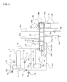
Fig. 4 is an explanatory view showing an example of a GH formation plant, and illustrating the example of the GH formation plant suitable for practicing the method of molding a GH pellet according to the present invention. -
Fig. 5 is a block diagram for explaining an example of a structure of a conventional GH formation plant which is applied at a natural GH shipping site. - Hereinafter, a method of molding a gas hydrate pellet according to the present invention will be concretely described based on the preferred embodiments as illustrated in the drawings.
- In
Fig. 4 , an apparatus for molding GH pellets comprising a compression chamber and a compression plunger and adapted for practicing the invention. - In a GH formation plant, a raw material gas G and water W are fed in the
generator 1 via a rawmaterial feed pipe 11 and arefrigerant feed pipe 12, respectively. GH slurry is generated by reacting the raw material gas G and the water W in thegenerator 1, then the GH slurry is fed in acompression chamber 21 of apellet molding apparatus 20 via aslurry feed pipe 13. On the other hand, an unreacted refrigerant is recovered from thegenerator 1 by arefrigerant recirculation pump 1a via areturn pipe 1b. A discharge end of therefrigerant recirculation pump 1a is connected to therefrigerant feed pipe 12. Therefrigerant feed pipe 12 is provided with aregulation valve 12a, and a valve opening of theregulation valve 12a is regulated based on measurement values of apressure gauge 11c which measures an internal pressure of thegenerator 1. - The
compression chamber 21 comprises aninner cylinder 21a of cylindrical shape and anouter cylinder 21b which accommodates theinner cylinder 21a. Theinner cylinder 21a accommodates acompression plunger 21e capable of advancing and retreating slidingly in a direction of an axis O of theinner cylinder 21a. Thecompression plunger 21e advances and retreats by operation of a not-shown drive source. A hydraulically drive source, a motor drive source with a rack-pinion mechanism which converts an output power of a motor into a linear motion, or the like may be used as the drive source. A part of theinner cylinder 21a defines ascreening part 21c which is provided with perforations of suitable size. - The
compression chamber 21 is communicated with a coolingchamber 23 via agate valve 22, at an advanced end position of thecompression plunger 21e. Opening thegate valve 22 allows communication between thecompression chamber 21 and the coolingchamber 23. The coolingchamber 23 is in the form of a cylinder having an inner diameter equal to or greater than that of theinner cylinder 21a of thecompression chamber 21. - The cooling
chamber 23 is provided with apellet transfer valve 24, at an end opposite from thecompression chamber 21. Thepellet transfer valve 24 comprises avalve casing 24b accommodating aspherical valve element 24a, like a so-called ball valve. Thevalve element 24a includes a holdingchamber 24c. The holdingchamber 24c is sized with an inner diameter equal to or greater than that of the coolingchamber 23 and a depth sufficient to accommodate a GH pellet. A part of the holdingchamber 24c is open and defines anopening 24d. Theopening 24d is designed to be located at a receiving position facing the coolingchamber 23, and at a discharge position facing afeed path 25 for feeding the GH pellet to a dewatering process in response to turning of thevalve element 24a relative to thevalve casing 24b. When thefeed path 25 communicates with a following depressurizing process, an internal pressure thereof is ambient pressure, therefore, the coolingchamber 23 is not allowed to communicate with thefeed path 25 by rotating action of thevalve element 24a. For example, thevalve element 24a is adapted to be positioned at the discharge portion by turning from the receiving position as shown inFig. 4 in a clockwise direction, and to be positioned at the receiving position by turning from the discharge position in an anti-clockwise direction. - A lower portion of the
compression chamber 21 is connected to aslurry recovery pipe 21d. Aslurry circulation pump 11a is connected at a suction end to theslurry recovery pipe 21d, and at a discharge end to the rawmaterial feed pipe 11. Further, theslurry circulation pump 11a is connected also at the suction end to a discharge end of the rawmaterial feed pump 11b. That is to say, water squeezed out during process of the GH slurry in thecompression chamber 21 joins with the raw material fed by the rawmaterial feed pump 11b, and is returned in thegenerator 1 by theslurry circulation pump 11a. Theslurry feed pipe 13 is connected at a mid-position along its length to theslurry recovery pipe 21d by way of areturn pipe 13a. Thereturn pipe 13a is provided with areturn valve 13b at a mid-position along its length. A gas/water buffer 21h is connected via a back-pressure pipe 21i to a back-pressure chamber 21g which is located opposite from thecompression chamber 21 with respect to thecompression plunger 21e. The gas/water buffer 21 h is connected to theslurry recovery pipe 21 d via aregulation valve 21j. - In the cooling
chamber 23, a high-pressure cooling medium is fed via arefrigerant feed pipe 23a, and the cooling medium is recovered via arefrigerant recovery pipe 23c by arecovery pump 23b. Meanwhile, therefrigerant recovery pipe 23b is provided with arefrigerant buffer 23d which is adapted to stabilize operation of therecovery pump 23c by transiently storing the refrigerant recovered. Adischarge pipe 23e which is connected to therecovery pump 23c at a discharge end of therecovery pump 23c, is connected to a not-shown refrigerant source such as a cooler to which therefrigerant feed pipe 23a is also connected, whereby a temporary cooling medium which is fed in the coolingchamber 23 from the refrigerant source is recovered. - For molding a GH pellet, first, the
compression plunger 21e is located at a backmost retreated position, namely, at a position most away from the coolingchamber 23, thegate valve 22 is closed, and thevalve element 24a of thepellet transfer valve 24 is located at the receiving position. At that time, theinner cylinder 21a of thecompression chamber 21 is fed with GH slurry, and charged with a predetermined amount of the GH slurry. - For example, when a 10-weight percent GH slurry is fed in the
inner cylinder 21a, theplunger 21e advances, thereby the GH slurry in thecompression chamber 21 is compressed and thus squeezed out water to a 90-weight percent GH in the form of a GH pellet P. The water squeezed out here flows out through thescreening portion 21c into theouter cylinder 21b and is recovered via theslurry recovery pipe 21d by theslurry circulation pump 11a, and is returned into thegenerator 1. -
Fig. 1 (a) shows that thecompression plunger 21e is located at a back position with the GH slurry being fed in thecompression chamber 21. Subsequent to this state, thecompression plunger 21e is advanced and the GH slurry fed in thecompression chamber 21 is squeezed out water. At that time, the advancing speed, namely the compression speed of thecompression plunger 21e is minimized. Where D (m) represents a length of thecompression chamber 21 as shown inFig. 1 (a) , the compression speed Vp is preferably given by the following.
- When the GH pellet is molded, the
gate valve 22 is opened to communicate thecompression chamber 21 with the coolingchamber 23. Thecompression chamber 21 has the same internal pressure as the coolingchamber 23 and the holdingchamber 24c, since thepellet transfer valve 24 is located at the receiving position with respect to thefeed path 25. Thecompression plunger 21e continues to advance to a position of thegate valve 22, and the 90-weight-percent GH in the form of the pellet to which water is squeezed out is pushed out of thecompression chamber 21 and fed in the coolingchamber 23. By the way, in the case that the coolingchamber 23 is occupied by a GH pellet which has been molded in a precedent cycle, the GH pellet P in the same quantity as the GH pellet to be fed in the coolingchamber 23 is pushed out of the coolingchamber 23 into the holdingchamber 24c when thecompression plunger 21e reaches the fully advanced end position. When the GH pellet is pushed out of thecompression chamber 21 by advancing thecompression plunger 21e, thegate valve 22 is closed. - The
gate valve 22 is closed, thecompression plunger 21e begins to retreat, and the GH slurry is fed in theinner cylinder 21a. Since the coolingchamber 23 is made airtight when thegate valve 22 is closed, the GH pellet in the coolingchamber 23 is cooled to such a temperature that the GH pellet is kept stable even under ambient pressure, by feeding the refrigerant through therefrigerant feed pipe 23a in the coolingchamber 23. - At retreat of the
compression plunger 21a to the backmost end position, thevalve element 24a is turned from the receiving position to the discharge position. At that time, an end portion of the coolingchamber 23 is kept closed with thevalve element 24a by turning thevalve element 24a in the clockwise direction. While thevalve element 24a is located at the discharge position, the GH pellet P is depressurized, and the GH pellet P received in the holdingchamber 24c falls in thefeed path 25. Subsequently, thevalve element 24a is returned to the receiving position by turning thevalve element 24a from the discharge position in the anti-clockwise direction, inFig. 4 . Then, a series of the process by the apparatus for molding a GH pellet is completed. - By repeating the above operation, the GH pellets may be produced successively, and the GH pellets molded in this manner may have increased strength.
-
Figs. 2 and3 show the relationship between the axial stress sv' (MPa) and the axial strain Epa (%) as the results of the tests performed in regard to strength of GH pellets produced by the molding method according to the present invention, by using a triaxial compression test apparatus. The test is performed by placing the GH pellets obtained by using the apparatus for molding GH pellets as shown inFig. 4 , in the triaxial compression test apparatus. The triaxial compression test is adapted for the GH only in the solid state. The results of the tests are equivalent to the results based on repeated compressions in thecompression chamber 21 as shown inFig. 4 . For shearing testing, an axial stress (stress in the vertical direction) relative to a predetermined lateral stress (stress in the horizontal direction) sh' is applied to specimens in the triaxial test apparatus. In the test shown inFig. 2 , the lateral stresses sh' are 1.0, 1.5 and 3.0 (MPa), respectively, and the length D of a stroke of the compression plunger represents the initial length L0 of the GH pellet. The axial strain Epa given by theEquation 2 is obtained with increasing the axial stress sv'. The speed of a plunger for applying the axial stress sv' is according to theabove Equation 1, and equal to the initial length L0 of GH pellet x 10-4 (m/min).
- L represents the length of GH pellet at the time.
-
Fig. 3 shows the result of the test where the lateral stresses sh' are 1.0, 2.0 and 3.0 (MPa), respectively and the advancing speed of the compression plunger is equal to the initial length L0 of the GH pellet x 10-3 (m/min). - As shown in
Figs. 2 and3 , the lager the axial strain Epa, the more the axial stress sv' is increased. We can determine that in either of the conditions, the strength of the pellet is increased by compression. That is, we can determine that the strength of a GH pellet is increased by molding the GH pellet under compression applied to the GH by advancing the compression plunger at low speed. For performing the strength test, the GH pellet is molded so as to be suitable to be placed in the triaxial compression test apparatus, and is used as specimen for the strength test. In the GH formation plant, GH pellets are molded by compressing GH slurry by advancing a compression plunger at the lowest speed. - According to the method of molding GH pellets of the present invention, the GH pellets with high strength can be molded, therefore, easiness of handling of GH pellets during transportation and storage is optimized, and the method of molding GH pellets of the present invention can make a contribution to improved utility value of GH as energy.
-
- 1
- Generator
- 20
- Pellet molding apparatus
- 21
- Compression chamber
- 21a
- Inner cylinder
- 21b
- Outer cylinder
- 21e
- Compression plunger
- 22
- Gate valve
- 23
- Cooling chamber
- 25
- Feed path
Claims (2)
- A method of molding a gas hydrate pellet in a gas hydrate formation plant including a generator in which a raw material gas and water are fed and adapted for reacting the raw material gas with water under high pressure in the generator to produce a gas hydrate slurry and removing water from the gas hydrate slurry to mold the gas hydrate slurry into a gas hydrate pellet of desired size, the method, comprising the steps of:feeding the gas hydrate slurry in a cylindrical compression chamber provided with a compression plunger capable of advancing and retreating in the cylindrical compression chamber in a direction of an axis of the compression chamber, and,advancing the compression plunger to exert compression action for squeezing out water from the gas hydrate slurry to mold the gas hydrate pellet,wherein an advancing speed of the compression plunger is set minimum.
- The method of molding a gas hydrate pellet as set forth in Claim 1, wherein the advancing speed of the compression plunger is less than a value expressed by length of the pellet before compression x 10-2 (m/min).
Applications Claiming Priority (2)
| Application Number | Priority Date | Filing Date | Title |
|---|---|---|---|
| JP2011073903 | 2011-03-30 | ||
| PCT/JP2012/056957 WO2012132980A1 (en) | 2011-03-30 | 2012-03-19 | Method of molding gas hydrate pellet |
Publications (3)
| Publication Number | Publication Date |
|---|---|
| EP2692837A1 true EP2692837A1 (en) | 2014-02-05 |
| EP2692837A4 EP2692837A4 (en) | 2014-10-01 |
| EP2692837B1 EP2692837B1 (en) | 2018-12-26 |
Family
ID=46930712
Family Applications (1)
| Application Number | Title | Priority Date | Filing Date |
|---|---|---|---|
| EP12765558.7A Active EP2692837B1 (en) | 2011-03-30 | 2012-03-19 | Method of molding gas hydrate pellet |
Country Status (9)
| Country | Link |
|---|---|
| US (1) | US9039949B2 (en) |
| EP (1) | EP2692837B1 (en) |
| JP (1) | JPWO2012132980A1 (en) |
| AU (1) | AU2012234629B2 (en) |
| BR (1) | BR112013034023A2 (en) |
| CA (1) | CA2834763C (en) |
| ES (1) | ES2716011T3 (en) |
| RU (1) | RU2584685C2 (en) |
| WO (1) | WO2012132980A1 (en) |
Families Citing this family (6)
| Publication number | Priority date | Publication date | Assignee | Title |
|---|---|---|---|---|
| US9744508B2 (en) * | 2013-06-27 | 2017-08-29 | Dongshin Hydraulics Co., Ltd. | Apparatus for revaporizing gas hydrate pellets |
| WO2016108177A2 (en) * | 2014-12-28 | 2016-07-07 | Yehoshua Fishler | Gas hydrate transportation and storage system and method |
| RU2643370C1 (en) * | 2017-06-16 | 2018-02-01 | Федеральное государственное бюджетное учреждение науки Объединенный институт высоких температур Российской академии наук (ОИВТ РАН) | Plant for production of methane hydrate |
| CN108102760B (en) * | 2018-01-24 | 2024-08-02 | 南阳理工学院 | Biomass solid particle forming machine |
| CN108410528B (en) * | 2018-05-30 | 2020-11-24 | 河南理工大学 | A kind of natural biomass solution for improving gas hydration rate and preparation method thereof |
| CN113900143B (en) * | 2021-09-29 | 2023-03-14 | 中国石油化工股份有限公司 | Method and device for determining attribute characteristics of natural gas hydrate and server |
Family Cites Families (15)
| Publication number | Priority date | Publication date | Assignee | Title |
|---|---|---|---|---|
| US3070003A (en) * | 1960-05-16 | 1962-12-25 | French Oil Mill Machinery | Automatic cage type press |
| JPH0787999B2 (en) | 1990-06-22 | 1995-09-27 | ティーディーケイ株式会社 | Wet powder molding apparatus and wet powder molding method |
| US6874411B2 (en) * | 2000-04-28 | 2005-04-05 | Ntn Corporation | Recycle of grinding sludge |
| KR20030004434A (en) * | 2001-03-29 | 2003-01-14 | 미츠비시 쥬고교 가부시키가이샤 | Gas hydrate production device and gas hydrate dehydrating device |
| RU2418846C2 (en) * | 2006-03-30 | 2011-05-20 | Мицуи Инджиниринг энд Шипбилдинг Ко., Лтд. | Procedure for production of granules of gas hydrate |
| WO2007116456A1 (en) * | 2006-03-30 | 2007-10-18 | Mitsui Engineering & Shipbuilding Co., Ltd. | Process for producing gas hydrate pellet |
| JP4897333B2 (en) | 2006-03-31 | 2012-03-14 | 三井造船株式会社 | Method and apparatus for producing gas hydrate pellets |
| RU2447134C2 (en) * | 2007-03-30 | 2012-04-10 | Мицуи Инджиниринг энд Шипбилдинг Ко., Лтд. | Hydrated gas article extruder |
| WO2009044468A1 (en) * | 2007-10-03 | 2009-04-09 | Mitsui Engineering & Shipbuilding Co., Ltd. | Process and apparatus for producing gas hydrate pellet |
| JP2009221458A (en) | 2008-02-22 | 2009-10-01 | Mitsui Zosen Akishima Kenkyusho:Kk | Purification process for gas hydrate |
| JP5052386B2 (en) * | 2008-03-31 | 2012-10-17 | 三井造船株式会社 | Gas hydrate manufacturing equipment |
| JP4698698B2 (en) | 2008-03-31 | 2011-06-08 | 三井造船株式会社 | Gas hydrate granulator |
| JP5153414B2 (en) | 2008-03-31 | 2013-02-27 | 三井造船株式会社 | NGH pellet pressing and dehydration |
| JP2010235868A (en) | 2009-03-31 | 2010-10-21 | Mitsui Eng & Shipbuild Co Ltd | Gas hydrate pellet forming equipment |
| US8486340B2 (en) * | 2009-09-15 | 2013-07-16 | Korea Institute Of Industrial Technology | Apparatus and method for continuously producing and pelletizing gas hydrates using dual cylinder |
-
2012
- 2012-03-19 AU AU2012234629A patent/AU2012234629B2/en active Active
- 2012-03-19 ES ES12765558T patent/ES2716011T3/en active Active
- 2012-03-19 BR BR112013034023A patent/BR112013034023A2/en not_active IP Right Cessation
- 2012-03-19 WO PCT/JP2012/056957 patent/WO2012132980A1/en not_active Ceased
- 2012-03-19 CA CA2834763A patent/CA2834763C/en active Active
- 2012-03-19 RU RU2013148118/04A patent/RU2584685C2/en active
- 2012-03-19 JP JP2013507395A patent/JPWO2012132980A1/en active Pending
- 2012-03-19 EP EP12765558.7A patent/EP2692837B1/en active Active
- 2012-03-19 US US14/114,728 patent/US9039949B2/en active Active
Also Published As
| Publication number | Publication date |
|---|---|
| WO2012132980A1 (en) | 2012-10-04 |
| RU2584685C2 (en) | 2016-05-20 |
| AU2012234629A1 (en) | 2013-11-14 |
| BR112013034023A2 (en) | 2018-07-10 |
| JPWO2012132980A1 (en) | 2014-07-28 |
| US20140203471A1 (en) | 2014-07-24 |
| EP2692837B1 (en) | 2018-12-26 |
| CA2834763A1 (en) | 2012-10-04 |
| AU2012234629B2 (en) | 2017-03-23 |
| CA2834763C (en) | 2019-09-24 |
| EP2692837A4 (en) | 2014-10-01 |
| RU2013148118A (en) | 2015-05-10 |
| ES2716011T3 (en) | 2019-06-07 |
| US9039949B2 (en) | 2015-05-26 |
Similar Documents
| Publication | Publication Date | Title |
|---|---|---|
| EP2692837B1 (en) | Method of molding gas hydrate pellet | |
| JP2012208015A (en) | Breaking strength testing method for gas hydrate pellet | |
| Cheng et al. | Quantitative analysis of methane hydrate formation in size-varied porous media for gas storage and transportation application | |
| Burla et al. | Enrichment of gas storage in clathrate hydrates by optimizing the molar liquid water–gas ratio | |
| JPWO2011111189A1 (en) | Biomass hydrothermal decomposition apparatus and temperature control method thereof, organic raw material production system using biomass raw material | |
| CN103214405B (en) | A kind of production equipment of liquid Sodium Dimethyldithiocarbamate and production method thereof | |
| Cheng et al. | Direct reduction of nickel catalyst with model bio-compounds | |
| WO2020117129A9 (en) | Apparatus and method for forming gas hydrates | |
| EP2267105A1 (en) | Process and apparatus for producing gas hydrate | |
| KR20120023912A (en) | Method for manufacturing of gas hydrate and device for manufacturing of gas hydrate and for measurement of raman peak | |
| Jeenmuang et al. | Scalable continuous hydrate systems for natural gas storage and transportation: Development from lab-scale pelletization to industrial application | |
| CN104628062B (en) | Method for gasifying unsymmetrical dimethylhydrazine waste liquor through supercritical water | |
| JP4638706B2 (en) | Gas hydrate manufacturing method | |
| EP2133404B1 (en) | Gas hydrate compression molding machine | |
| JP5302065B2 (en) | Gas hydrate pellet forming equipment | |
| JP2006045128A (en) | Methane hydrate decomposition method and decomposition apparatus | |
| JP2009221458A (en) | Purification process for gas hydrate | |
| JP2010235868A (en) | Gas hydrate pellet forming equipment | |
| JP2012115880A (en) | Device and method for forming gas hydrate pellet | |
| JP2013184950A (en) | Method for production of formic acid | |
| Cheng et al. | Study on the micro-macro kinetic and amino acid-enhanced separation of CO2-CH4 via sII hydrate | |
| Wang et al. | Novel supercritical CO2 coal upgrading technology: Experimental and simulation investigation | |
| JP2012005944A (en) | Apparatus for separating water sticking to gas hydrate | |
| JP2012046696A (en) | Device and method for generating mixed gas hydrate, and device for producing mixed gas hydrate pellet | |
| JP2012000541A (en) | Gas hydrate pellet molding apparatus and gas hydrate pellet |
Legal Events
| Date | Code | Title | Description |
|---|---|---|---|
| PUAI | Public reference made under article 153(3) epc to a published international application that has entered the european phase |
Free format text: ORIGINAL CODE: 0009012 |
|
| 17P | Request for examination filed |
Effective date: 20131030 |
|
| AK | Designated contracting states |
Kind code of ref document: A1 Designated state(s): AL AT BE BG CH CY CZ DE DK EE ES FI FR GB GR HR HU IE IS IT LI LT LU LV MC MK MT NL NO PL PT RO RS SE SI SK SM TR |
|
| DAX | Request for extension of the european patent (deleted) | ||
| A4 | Supplementary search report drawn up and despatched |
Effective date: 20140828 |
|
| RIC1 | Information provided on ipc code assigned before grant |
Ipc: B30B 9/04 20060101ALI20140822BHEP Ipc: B01J 2/22 20060101ALI20140822BHEP Ipc: C10L 3/06 20060101AFI20140822BHEP |
|
| REG | Reference to a national code |
Ref country code: DE Ref legal event code: R079 Ref document number: 602012055158 Country of ref document: DE Free format text: PREVIOUS MAIN CLASS: C10L0003060000 Ipc: B30B0009060000 |
|
| GRAP | Despatch of communication of intention to grant a patent |
Free format text: ORIGINAL CODE: EPIDOSNIGR1 |
|
| STAA | Information on the status of an ep patent application or granted ep patent |
Free format text: STATUS: GRANT OF PATENT IS INTENDED |
|
| RIC1 | Information provided on ipc code assigned before grant |
Ipc: B30B 9/06 20060101AFI20180612BHEP |
|
| INTG | Intention to grant announced |
Effective date: 20180705 |
|
| RIC1 | Information provided on ipc code assigned before grant |
Ipc: B30B 9/06 20060101AFI20180622BHEP Ipc: C10L 3/10 20060101ALI20180622BHEP |
|
| GRAS | Grant fee paid |
Free format text: ORIGINAL CODE: EPIDOSNIGR3 |
|
| GRAA | (expected) grant |
Free format text: ORIGINAL CODE: 0009210 |
|
| STAA | Information on the status of an ep patent application or granted ep patent |
Free format text: STATUS: THE PATENT HAS BEEN GRANTED |
|
| AK | Designated contracting states |
Kind code of ref document: B1 Designated state(s): AL AT BE BG CH CY CZ DE DK EE ES FI FR GB GR HR HU IE IS IT LI LT LU LV MC MK MT NL NO PL PT RO RS SE SI SK SM TR |
|
| REG | Reference to a national code |
Ref country code: GB Ref legal event code: FG4D |
|
| REG | Reference to a national code |
Ref country code: CH Ref legal event code: EP |
|
| REG | Reference to a national code |
Ref country code: AT Ref legal event code: REF Ref document number: 1080827 Country of ref document: AT Kind code of ref document: T Effective date: 20190115 |
|
| REG | Reference to a national code |
Ref country code: DE Ref legal event code: R096 Ref document number: 602012055158 Country of ref document: DE |
|
| REG | Reference to a national code |
Ref country code: IE Ref legal event code: FG4D |
|
| PG25 | Lapsed in a contracting state [announced via postgrant information from national office to epo] |
Ref country code: LV Free format text: LAPSE BECAUSE OF FAILURE TO SUBMIT A TRANSLATION OF THE DESCRIPTION OR TO PAY THE FEE WITHIN THE PRESCRIBED TIME-LIMIT Effective date: 20181226 Ref country code: HR Free format text: LAPSE BECAUSE OF FAILURE TO SUBMIT A TRANSLATION OF THE DESCRIPTION OR TO PAY THE FEE WITHIN THE PRESCRIBED TIME-LIMIT Effective date: 20181226 Ref country code: LT Free format text: LAPSE BECAUSE OF FAILURE TO SUBMIT A TRANSLATION OF THE DESCRIPTION OR TO PAY THE FEE WITHIN THE PRESCRIBED TIME-LIMIT Effective date: 20181226 Ref country code: NO Free format text: LAPSE BECAUSE OF FAILURE TO SUBMIT A TRANSLATION OF THE DESCRIPTION OR TO PAY THE FEE WITHIN THE PRESCRIBED TIME-LIMIT Effective date: 20190326 Ref country code: BG Free format text: LAPSE BECAUSE OF FAILURE TO SUBMIT A TRANSLATION OF THE DESCRIPTION OR TO PAY THE FEE WITHIN THE PRESCRIBED TIME-LIMIT Effective date: 20190326 Ref country code: FI Free format text: LAPSE BECAUSE OF FAILURE TO SUBMIT A TRANSLATION OF THE DESCRIPTION OR TO PAY THE FEE WITHIN THE PRESCRIBED TIME-LIMIT Effective date: 20181226 |
|
| REG | Reference to a national code |
Ref country code: NL Ref legal event code: MP Effective date: 20181226 |
|
| REG | Reference to a national code |
Ref country code: LT Ref legal event code: MG4D |
|
| PG25 | Lapsed in a contracting state [announced via postgrant information from national office to epo] |
Ref country code: RS Free format text: LAPSE BECAUSE OF FAILURE TO SUBMIT A TRANSLATION OF THE DESCRIPTION OR TO PAY THE FEE WITHIN THE PRESCRIBED TIME-LIMIT Effective date: 20181226 Ref country code: GR Free format text: LAPSE BECAUSE OF FAILURE TO SUBMIT A TRANSLATION OF THE DESCRIPTION OR TO PAY THE FEE WITHIN THE PRESCRIBED TIME-LIMIT Effective date: 20190327 Ref country code: AL Free format text: LAPSE BECAUSE OF FAILURE TO SUBMIT A TRANSLATION OF THE DESCRIPTION OR TO PAY THE FEE WITHIN THE PRESCRIBED TIME-LIMIT Effective date: 20181226 Ref country code: SE Free format text: LAPSE BECAUSE OF FAILURE TO SUBMIT A TRANSLATION OF THE DESCRIPTION OR TO PAY THE FEE WITHIN THE PRESCRIBED TIME-LIMIT Effective date: 20181226 |
|
| REG | Reference to a national code |
Ref country code: ES Ref legal event code: FG2A Ref document number: 2716011 Country of ref document: ES Kind code of ref document: T3 Effective date: 20190607 |
|
| REG | Reference to a national code |
Ref country code: AT Ref legal event code: MK05 Ref document number: 1080827 Country of ref document: AT Kind code of ref document: T Effective date: 20181226 |
|
| PG25 | Lapsed in a contracting state [announced via postgrant information from national office to epo] |
Ref country code: NL Free format text: LAPSE BECAUSE OF FAILURE TO SUBMIT A TRANSLATION OF THE DESCRIPTION OR TO PAY THE FEE WITHIN THE PRESCRIBED TIME-LIMIT Effective date: 20181226 |
|
| PG25 | Lapsed in a contracting state [announced via postgrant information from national office to epo] |
Ref country code: PL Free format text: LAPSE BECAUSE OF FAILURE TO SUBMIT A TRANSLATION OF THE DESCRIPTION OR TO PAY THE FEE WITHIN THE PRESCRIBED TIME-LIMIT Effective date: 20181226 Ref country code: IT Free format text: LAPSE BECAUSE OF FAILURE TO SUBMIT A TRANSLATION OF THE DESCRIPTION OR TO PAY THE FEE WITHIN THE PRESCRIBED TIME-LIMIT Effective date: 20181226 Ref country code: PT Free format text: LAPSE BECAUSE OF FAILURE TO SUBMIT A TRANSLATION OF THE DESCRIPTION OR TO PAY THE FEE WITHIN THE PRESCRIBED TIME-LIMIT Effective date: 20190426 Ref country code: CZ Free format text: LAPSE BECAUSE OF FAILURE TO SUBMIT A TRANSLATION OF THE DESCRIPTION OR TO PAY THE FEE WITHIN THE PRESCRIBED TIME-LIMIT Effective date: 20181226 |
|
| PG25 | Lapsed in a contracting state [announced via postgrant information from national office to epo] |
Ref country code: RO Free format text: LAPSE BECAUSE OF FAILURE TO SUBMIT A TRANSLATION OF THE DESCRIPTION OR TO PAY THE FEE WITHIN THE PRESCRIBED TIME-LIMIT Effective date: 20181226 Ref country code: SK Free format text: LAPSE BECAUSE OF FAILURE TO SUBMIT A TRANSLATION OF THE DESCRIPTION OR TO PAY THE FEE WITHIN THE PRESCRIBED TIME-LIMIT Effective date: 20181226 Ref country code: IS Free format text: LAPSE BECAUSE OF FAILURE TO SUBMIT A TRANSLATION OF THE DESCRIPTION OR TO PAY THE FEE WITHIN THE PRESCRIBED TIME-LIMIT Effective date: 20190426 Ref country code: SM Free format text: LAPSE BECAUSE OF FAILURE TO SUBMIT A TRANSLATION OF THE DESCRIPTION OR TO PAY THE FEE WITHIN THE PRESCRIBED TIME-LIMIT Effective date: 20181226 Ref country code: EE Free format text: LAPSE BECAUSE OF FAILURE TO SUBMIT A TRANSLATION OF THE DESCRIPTION OR TO PAY THE FEE WITHIN THE PRESCRIBED TIME-LIMIT Effective date: 20181226 |
|
| REG | Reference to a national code |
Ref country code: DE Ref legal event code: R097 Ref document number: 602012055158 Country of ref document: DE |
|
| REG | Reference to a national code |
Ref country code: DE Ref legal event code: R119 Ref document number: 602012055158 Country of ref document: DE |
|
| PG25 | Lapsed in a contracting state [announced via postgrant information from national office to epo] |
Ref country code: AT Free format text: LAPSE BECAUSE OF FAILURE TO SUBMIT A TRANSLATION OF THE DESCRIPTION OR TO PAY THE FEE WITHIN THE PRESCRIBED TIME-LIMIT Effective date: 20181226 Ref country code: DK Free format text: LAPSE BECAUSE OF FAILURE TO SUBMIT A TRANSLATION OF THE DESCRIPTION OR TO PAY THE FEE WITHIN THE PRESCRIBED TIME-LIMIT Effective date: 20181226 Ref country code: MC Free format text: LAPSE BECAUSE OF FAILURE TO SUBMIT A TRANSLATION OF THE DESCRIPTION OR TO PAY THE FEE WITHIN THE PRESCRIBED TIME-LIMIT Effective date: 20181226 |
|
| REG | Reference to a national code |
Ref country code: CH Ref legal event code: PL |
|
| PLBE | No opposition filed within time limit |
Free format text: ORIGINAL CODE: 0009261 |
|
| STAA | Information on the status of an ep patent application or granted ep patent |
Free format text: STATUS: NO OPPOSITION FILED WITHIN TIME LIMIT |
|
| GBPC | Gb: european patent ceased through non-payment of renewal fee |
Effective date: 20190326 |
|
| PG25 | Lapsed in a contracting state [announced via postgrant information from national office to epo] |
Ref country code: LU Free format text: LAPSE BECAUSE OF NON-PAYMENT OF DUE FEES Effective date: 20190319 |
|
| 26N | No opposition filed |
Effective date: 20190927 |
|
| REG | Reference to a national code |
Ref country code: BE Ref legal event code: MM Effective date: 20190331 |
|
| PG25 | Lapsed in a contracting state [announced via postgrant information from national office to epo] |
Ref country code: LI Free format text: LAPSE BECAUSE OF NON-PAYMENT OF DUE FEES Effective date: 20190331 Ref country code: DE Free format text: LAPSE BECAUSE OF NON-PAYMENT OF DUE FEES Effective date: 20191001 Ref country code: GB Free format text: LAPSE BECAUSE OF NON-PAYMENT OF DUE FEES Effective date: 20190326 Ref country code: CH Free format text: LAPSE BECAUSE OF NON-PAYMENT OF DUE FEES Effective date: 20190331 Ref country code: IE Free format text: LAPSE BECAUSE OF NON-PAYMENT OF DUE FEES Effective date: 20190319 |
|
| PG25 | Lapsed in a contracting state [announced via postgrant information from national office to epo] |
Ref country code: SI Free format text: LAPSE BECAUSE OF FAILURE TO SUBMIT A TRANSLATION OF THE DESCRIPTION OR TO PAY THE FEE WITHIN THE PRESCRIBED TIME-LIMIT Effective date: 20181226 Ref country code: BE Free format text: LAPSE BECAUSE OF NON-PAYMENT OF DUE FEES Effective date: 20190331 Ref country code: FR Free format text: LAPSE BECAUSE OF NON-PAYMENT OF DUE FEES Effective date: 20190331 |
|
| PG25 | Lapsed in a contracting state [announced via postgrant information from national office to epo] |
Ref country code: TR Free format text: LAPSE BECAUSE OF FAILURE TO SUBMIT A TRANSLATION OF THE DESCRIPTION OR TO PAY THE FEE WITHIN THE PRESCRIBED TIME-LIMIT Effective date: 20181226 |
|
| PG25 | Lapsed in a contracting state [announced via postgrant information from national office to epo] |
Ref country code: MT Free format text: LAPSE BECAUSE OF NON-PAYMENT OF DUE FEES Effective date: 20190319 |
|
| REG | Reference to a national code |
Ref country code: ES Ref legal event code: PC2A Owner name: NATIONAL INSTITUTE OF ADVANCED INDUSTRIAL SCIENCE AND TECHNOLOGY Effective date: 20200807 |
|
| PG25 | Lapsed in a contracting state [announced via postgrant information from national office to epo] |
Ref country code: CY Free format text: LAPSE BECAUSE OF FAILURE TO SUBMIT A TRANSLATION OF THE DESCRIPTION OR TO PAY THE FEE WITHIN THE PRESCRIBED TIME-LIMIT Effective date: 20181226 |
|
| PG25 | Lapsed in a contracting state [announced via postgrant information from national office to epo] |
Ref country code: HU Free format text: LAPSE BECAUSE OF FAILURE TO SUBMIT A TRANSLATION OF THE DESCRIPTION OR TO PAY THE FEE WITHIN THE PRESCRIBED TIME-LIMIT; INVALID AB INITIO Effective date: 20120319 |
|
| PG25 | Lapsed in a contracting state [announced via postgrant information from national office to epo] |
Ref country code: MK Free format text: LAPSE BECAUSE OF FAILURE TO SUBMIT A TRANSLATION OF THE DESCRIPTION OR TO PAY THE FEE WITHIN THE PRESCRIBED TIME-LIMIT Effective date: 20181226 |
|
| PGFP | Annual fee paid to national office [announced via postgrant information from national office to epo] |
Ref country code: ES Payment date: 20250408 Year of fee payment: 14 |