EP2692653A1 - Blank and box having a tolerance on the folding line between walls - Google Patents
Blank and box having a tolerance on the folding line between walls Download PDFInfo
- Publication number
- EP2692653A1 EP2692653A1 EP12178695.8A EP12178695A EP2692653A1 EP 2692653 A1 EP2692653 A1 EP 2692653A1 EP 12178695 A EP12178695 A EP 12178695A EP 2692653 A1 EP2692653 A1 EP 2692653A1
- Authority
- EP
- European Patent Office
- Prior art keywords
- panel
- rectangular
- joined
- length
- blank
- Prior art date
- Legal status (The legal status is an assumption and is not a legal conclusion. Google has not performed a legal analysis and makes no representation as to the accuracy of the status listed.)
- Granted
Links
Images






Classifications
-
- B—PERFORMING OPERATIONS; TRANSPORTING
- B65—CONVEYING; PACKING; STORING; HANDLING THIN OR FILAMENTARY MATERIAL
- B65D—CONTAINERS FOR STORAGE OR TRANSPORT OF ARTICLES OR MATERIALS, e.g. BAGS, BARRELS, BOTTLES, BOXES, CANS, CARTONS, CRATES, DRUMS, JARS, TANKS, HOPPERS, FORWARDING CONTAINERS; ACCESSORIES, CLOSURES, OR FITTINGS THEREFOR; PACKAGING ELEMENTS; PACKAGES
- B65D5/00—Rigid or semi-rigid containers of polygonal cross-section, e.g. boxes, cartons or trays, formed by folding or erecting one or more blanks made of paper
- B65D5/02—Rigid or semi-rigid containers of polygonal cross-section, e.g. boxes, cartons or trays, formed by folding or erecting one or more blanks made of paper by folding or erecting a single blank to form a tubular body with or without subsequent folding operations, or the addition of separate elements, to close the ends of the body
- B65D5/0236—Rigid or semi-rigid containers of polygonal cross-section, e.g. boxes, cartons or trays, formed by folding or erecting one or more blanks made of paper by folding or erecting a single blank to form a tubular body with or without subsequent folding operations, or the addition of separate elements, to close the ends of the body with end closures formed by inward folding of flaps and securing them by adhesive tapes, labels or the like; for decoration purposes
-
- B—PERFORMING OPERATIONS; TRANSPORTING
- B65—CONVEYING; PACKING; STORING; HANDLING THIN OR FILAMENTARY MATERIAL
- B65D—CONTAINERS FOR STORAGE OR TRANSPORT OF ARTICLES OR MATERIALS, e.g. BAGS, BARRELS, BOTTLES, BOXES, CANS, CARTONS, CRATES, DRUMS, JARS, TANKS, HOPPERS, FORWARDING CONTAINERS; ACCESSORIES, CLOSURES, OR FITTINGS THEREFOR; PACKAGING ELEMENTS; PACKAGES
- B65D5/00—Rigid or semi-rigid containers of polygonal cross-section, e.g. boxes, cartons or trays, formed by folding or erecting one or more blanks made of paper
- B65D5/02—Rigid or semi-rigid containers of polygonal cross-section, e.g. boxes, cartons or trays, formed by folding or erecting one or more blanks made of paper by folding or erecting a single blank to form a tubular body with or without subsequent folding operations, or the addition of separate elements, to close the ends of the body
- B65D5/0227—Rigid or semi-rigid containers of polygonal cross-section, e.g. boxes, cartons or trays, formed by folding or erecting one or more blanks made of paper by folding or erecting a single blank to form a tubular body with or without subsequent folding operations, or the addition of separate elements, to close the ends of the body with end closures formed by inward folding of flaps and securing them by heat-sealing, by applying adhesive to the flaps or by staples
-
- B—PERFORMING OPERATIONS; TRANSPORTING
- B65—CONVEYING; PACKING; STORING; HANDLING THIN OR FILAMENTARY MATERIAL
- B65D—CONTAINERS FOR STORAGE OR TRANSPORT OF ARTICLES OR MATERIALS, e.g. BAGS, BARRELS, BOTTLES, BOXES, CANS, CARTONS, CRATES, DRUMS, JARS, TANKS, HOPPERS, FORWARDING CONTAINERS; ACCESSORIES, CLOSURES, OR FITTINGS THEREFOR; PACKAGING ELEMENTS; PACKAGES
- B65D5/00—Rigid or semi-rigid containers of polygonal cross-section, e.g. boxes, cartons or trays, formed by folding or erecting one or more blanks made of paper
- B65D5/20—Rigid or semi-rigid containers of polygonal cross-section, e.g. boxes, cartons or trays, formed by folding or erecting one or more blanks made of paper by folding-up portions connected to a central panel from all sides to form a container body, e.g. of tray-like form
- B65D5/2052—Rigid or semi-rigid containers of polygonal cross-section, e.g. boxes, cartons or trays, formed by folding or erecting one or more blanks made of paper by folding-up portions connected to a central panel from all sides to form a container body, e.g. of tray-like form characterised by integral closure-flaps
Definitions
- the invention relates to an assembly of a blank for a box and a tape used for sealing the box, said tape having a breadth B, said blank having a thickness T and a rectangular bottom panel, a first rectangular side panel joined to a first side of the rectangular bottom panel, a second rectangular side panel joined to a second side of the rectangular bottom panel opposite the first side thereof, a first rectangular end panel joined to a first end of the bottom panel, a second rectangular end panel joined to a second end of the bottom panel opposite the first end of the rectangular bottom panel, a first rectangular corner panel joined to a first side of the first end panel, a second rectangular corner panel joined to a second side of the first end panel opposite the first side thereof, a third rectangular corner panel joined to a first side of the second end panel, a fourth rectangular corner panel joined to a second side of the second end panel opposite the first side thereof, a rectangular top panel joined to the first the end panel such that it is arranged at the side of the first end panel opposite to the side where the bottom panel is joined to the first end
- Such a layout of a blank is known as the International fibreboard case code, also called the FEFCO-ESBO code 11th Edition, 2007, number 0410 M/A . From such a blank a box for packaging items can be erected which box is sealed by attaching tape over the seam between respective panels or by using glue.
- Drawbacks of the known assembly and blank are that sealing the box formed out of said known blank by using tape is relatively difficult to perform and in some cases during transport of the box the tape tears resulting in the unwanted opening of the erected box.
- a further drawback of the known blank is that it is relatively complicated to use for automated packaging of articles.
- an object of the invention to provide an alternative assembly of a blank for a box and a tape. It is a further object of the invention to provide an assembly of a blank for a box and a tape from which a box can be formed which can relatively easily be sealed by means of the tape. It is a further object of the invention to provide an assembly of a blank for a box and a tape from which a box can be formed which when sealed by means of the tape can be transported with a relative low risk of unwanted opening. Another object of the invention is to provide a blank for a box from which relatively easily a box can be folded around articles to be packaged in an automated way.
- At least one of these objects is achieved by providing an assembly of a blank for a box and a tape used for sealing the box, said tape having a breadth B, said blank having a thickness T and a rectangular bottom panel, a first rectangular side panel joined to a first side of the rectangular bottom panel, a second rectangular side panel joined to a second side of the rectangular bottom panel opposite the first side thereof, a first rectangular end panel joined to a first end of the bottom panel, a second rectangular end panel joined to a second end of the bottom panel opposite the first end of the rectangular bottom panel, a first rectangular corner panel joined to a first side of the first end panel, a second rectangular corner panel joined to a second side of the first end panel opposite the first side thereof, a third rectangular corner panel joined to a first side of the second end panel, a fourth rectangular corner panel joined to a second side of the second end panel opposite the first side thereof, a rectangular top panel joined to the first the end panel such that it is arranged at the side of the first end panel opposite to the side where the
- t is a tolerance value satisfying the relation 0 ⁇ t ⁇ 2T defining a tolerance with regard to the height, width and length of the panels of the blank, which dimensions due to the tolerance value may deviate a small amount depending on the material of which the blank is made and taking account of cutting, creasing and folding properties.
- the material is relatively thick compared to the box size (typically when the thickness is more than 1% of the length, width or height of the box)it is preferred that t is approximately equal to T, i.e. the thickness of the blank.
- the invention is based on the insight that the drawbacks of the known assembly and blank mentioned above are at least partly the result of the fact that the seam of a box folded from the blank is situated at an edge of the box.
- H - H1 ⁇ 1 ⁇ 2B and/or H - H2 ⁇ 1 ⁇ 2B such that after folding of the box the seam of the box is positioned at a distance of at least 1 ⁇ 2B from the edge of the box.
- a box can be obtained in which the horizontal seams are neatly arranged along one line around the external contour of the box, in a plane substantially parallel to the bottom and top plane of the assembled box. This makes it possible to easily apply a tape at least approximately centered with respect to the seam in a direction parallel to the seam, since the tape can be applied completely in a flat arrangement.
- the sealing tape does not extend over the top or bottom edges of the erected box, making it less prone to impact and tear and wear during handling and transport.
- the width of the side panels relates to the height of the box, in order to obtain a box that has seams along three exterior sides of the box, at a constant height with respect to the bottom plane of the assembled box, in which said height is such that the ease of closing and opening of the box are improved while the risk of untimely opening is reduced.
- At least one of the objects identified above is achieved by providing an assembly of a blank for a box and a tape used for sealing the box, said tape having a breadth B, said blank having a thickness T and a rectangular bottom panel, a first rectangular side panel joined to a first side of the rectangular bottom panel, a second rectangular side panel joined to a second side of the rectangular bottom panel opposite the first side thereof, a first rectangular end panel joined to a first end of the bottom panel, a second rectangular end panel joined to a second end of the bottom panel opposite the first end of the rectangular bottom panel, a first rectangular corner panel joined to a first side of the first end panel, a second rectangular corner panel joined to a second side of the first end panel opposite the first side thereof, a third rectangular corner panel joined to a first side of the second end panel, a fourth rectangular corner panel joined to a second side of the second end panel opposite the first side thereof, a rectangular top panel joined to the first the end panel such that it is arranged at the side of the first end
- the rectangular corner panels each have a length of about H.
- the rectangular corner panels each have a width of about H1 + 2t.
- Such a length of the corner panels is advantageous since, when folding them at the inside of the box, the height equals the internal height of the box, so that these corner panels act as a support between the bottom and top panel and thus give additional strength to the box which is beneficial during the assembly of the box, especially when this is done in an automated way, and which is also beneficial for handling the assembled box.
- H1 H2.
- This provides an improvement of the protection of items packaged within the box, but the circumference of the complete blank is not rectangular any more, which could lead to additional steps of manufacturing the blank.
- D ⁇ 6 cm, preferably D is at least about 1 cm, most preferably at least about 3 cm.
- protection of items packaged within the box is improved while using a relatively low amount of material for manufacturing the blank.
- the top side panels overlap the side panels with an amount of D or 2D it is ensured that opening of the box by breaking the tape, e.g. with a knife, does not damage the items packaged inside the box.
- breaking the tape e.g. with a knife
- the cut-outs have a length G (measured in longitudinal direction of the blank) with a value ranging between 0 and about 4T, preferably having a value of about 2T.
- the cut-out length may be 0, which simplifies the cutting process and limits the amount of generated waste material, in other cases wider cut-outs, up to 4T may be preferred to ease automated manufacturing of the box from the blank.
- the cut-out length is about 2T, in this manner sufficient material is cut out during manufacturing of the blank, which makes it possible to correctly fold the blank into a box without compromising the blank too much to obtain a strong box.
- the most advantageous embodiment can differ from situation to situation, depending on the type of products to be packaged, on the desired level of protection for the items in the box, on the sizes of the box, the thickness and stiffness of the blank material, automation aspects and customer preferences.
- each of the folding lines connecting neighboring panels are formed of a number of parallel score lines, preferably two or three parallel score lines, which are spaced at a mutual distance of t", so that it is possible to compensate for this stiffness and for possible tolerances in dimensions and thickness of the material from which the blank is manufactured.
- the folding lines between separate panels are staggered with respect to each other, i.e. are not in line with each other.
- the folding line between the bottom panel and the second side panel is not in line with the folding line between the first end panel and the first corner panel, but these folding lines have an offset t"'.
- the distance t" between the score lines and the offset t"' each preferably have a value in the range of T to 3T.
- Preferred values of t" depend on the stiffness and/or thickness of the blank material and possibly on the dimensions of the box to be assembled; for two parallel score lines a mutual distance between about T and about 2T is preferred and for three parallel score lines a mutual distance of about T is preferred.
- the blank is made of a single piece of board having a substantially uniform thickness of 1 cm or less, and preferably a thickness less than 0.5 cm.
- the blank has a length of about 2L + 2.5 H + 9t and a width of about W + H + 6t, wherein L, W and H are the inside dimensions of a box after folding it from the blank and wherein 0 ⁇ t ⁇ 2T, wherein T is the thickness of the blank.
- the blank has a length of about 2L + 2.5 H + 2D + 9t and a width of about W + H + 2D + 6t, wherein L, W and H are the inside dimensions of a box after folding it from the blank and wherein 0 ⁇ t ⁇ 2T, wherein T is the thickness of the blank.
- the tape integrally comprises tear means. Since in accordance with the invention the seam of the box (after proper folding) is situated at a single vertical height from the bottom, it is possible to easily apply a tape around the box at a reproducible defined position. In this manner a sealing tape integrally comprising tear means can be applied to the box in a manner that it is extremely user friendly to open the box, by simply tearing the tear means, such that the seam is exposed to be manually opened by the user without much effort.
- a single tape surrounding the entire box can be used to seal the box, it is in alternative embodiments possible to use two or more pieces of tape to seal the box. In addition these tapes need not necessarily surround the box completely.
- the invention further relates to a blank for an assembly according to the invention.
- the invention further relates to a box formed from any one of the embodiments of an assembly as described above, wherein L is the inside length of the box, W is the inside width of the box and H is the inside height of the box, the box being folded such from the blank that the only seams substantially parallel to the bottom and top plane are a seam for attaching the first side panel to the first top side panel, a seam for attaching the second side panel to the second top side panel, and a seam for attaching the top end panel to the second end panel; wherein said seams are formed on an external surface of the box and are situated at a same distance from the bottom panel, said distance being larger than or equal to 1 ⁇ 2B.
- the invention is further based on the insight that a box can be formed out of a blank for the inventive assembly wherein the box is sealed by other means than by tape, such as by glue or by wrapping, such as foil wrapping or shrink wrapping.
- the invention further relates to a blank, preferably for a box according to the invention, said blank having a thickness T and a rectangular bottom panel, a first rectangular side panel joined to a first side of the rectangular bottom panel, a second rectangular side panel joined to a second side of the rectangular bottom panel opposite the first side thereof, a first rectangular end panel joined to a first end of the bottom panel, a second rectangular end panel joined to a second end of the bottom panel opposite the first end of the rectangular bottom panel, a first rectangular corner panel joined to a first side of the first end panel, a second rectangular corner panel joined to a second side of the first end panel opposite the first side thereof, a third rectangular corner panel joined to a first side of the second end panel, a fourth rectangular corner panel joined to a second side of the second end panel opposite the first side thereof, a rectangular top panel joined to the first the end panel such that it is arranged at the side of the first end panel opposite to the side where the bottom panel is joined to the first end panel, a first rectangular top side panel joined to a
- the invention even further relates to a blank, preferably for a box according to the invention, said blank having a thickness T and a rectangular bottom panel, a first rectangular side panel joined to a first side of the rectangular bottom panel, a second rectangular side panel joined to a second side of the rectangular bottom panel opposite the first side thereof, a first rectangular end panel joined to a first end of the bottom panel, a second rectangular end panel joined to a second end of the bottom panel opposite the first end of the rectangular bottom panel, a first rectangular corner panel joined to a first side of the first end panel, a second rectangular corner panel joined to a second side of the first end panel opposite the first side thereof, a third rectangular corner panel joined to a first side of the second end panel, a fourth rectangular corner panel joined to a second side of the second end panel opposite the first side thereof, a rectangular top panel joined to the first the end panel such that it is arranged at the side of the first end panel opposite to the side where the bottom panel is joined to the first end panel, a first rectangular top side panel joined to
- the invention further relates to a blank, preferably for a box according to the invention, said blank having a thickness T and a rectangular bottom panel, a first rectangular side panel joined to a first side of the rectangular bottom panel, a second rectangular side panel joined to a second side of the rectangular bottom panel opposite the first side thereof, a first rectangular end panel joined to a first end of the bottom panel, a second rectangular end panel joined to a second end of the bottom panel opposite the first end of the rectangular bottom panel, a first rectangular corner panel joined to a first side of the first end panel, a second rectangular corner panel joined to a second side of the first end panel opposite the first side thereof, a third rectangular corner panel joined to a first side of the second end panel, a fourth rectangular corner panel joined to a second side of the second end panel opposite the first side thereof, a rectangular top panel joined to the first the end panel such that it is arranged at the side of the first end panel opposite to the side where the bottom panel is joined to the first end panel, a first rectangular top side panel joined to a
- the invention still further relates to a blank, preferably for a box according to the invention, said blank having a thickness T and a rectangular bottom panel, a first rectangular side panel joined to a first side of the rectangular bottom panel, a second rectangular side panel joined to a second side of the rectangular bottom panel opposite the first side thereof, a first rectangular end panel joined to a first end of the bottom panel, a second rectangular end panel joined to a second end of the bottom panel opposite the first end of the rectangular bottom panel, a first rectangular corner panel joined to a first side of the first end panel, a second rectangular corner panel joined to a second side of the first end panel opposite the first side thereof, a third rectangular corner panel joined to a first side of the second end panel, a fourth rectangular corner panel joined to a second side of the second end panel opposite the first side thereof, a rectangular top panel joined to the first the end panel such that it is arranged at the side of the first end panel opposite to the side where the bottom panel is joined to the first end panel, a first rectangular top side panel joined to
- the invention even further relates to a blank, preferably for a box according to the invention, said blank having a thickness T and a rectangular bottom panel, a first rectangular side panel joined to a first side of the rectangular bottom panel, a second rectangular side panel joined to a second side of the rectangular bottom panel opposite the first side thereof, a first rectangular end panel joined to a first end of the bottom panel, a second rectangular end panel joined to a second end of the bottom panel opposite the first end of the rectangular bottom panel, a first rectangular corner panel joined to a first side of the first end panel, a second rectangular corner panel joined to a second side of the first end panel opposite the first side thereof, a third rectangular corner panel joined to a first side of the second end panel, a fourth rectangular corner panel joined to a second side of the second end panel opposite the first side thereof, a rectangular top panel joined to the first the end panel such that it is arranged at the side of the first end panel opposite to the side where the bottom panel is joined to the first end panel, a first rectangular top side panel joined to
- the invention also relates to a blank, preferably for a box according to the invention, said blank having a thickness T and a rectangular bottom panel, a first rectangular side panel joined to a first side of the rectangular bottom panel, a second rectangular side panel joined to a second side of the rectangular bottom panel opposite the first side thereof, a first rectangular end panel joined to a first end of the bottom panel, a second rectangular end panel joined to a second end of the bottom panel opposite the first end of the rectangular bottom panel, a first rectangular corner panel joined to a first side of the first end panel, a second rectangular corner panel joined to a second side of the first end panel opposite the first side thereof, a third rectangular corner panel joined to a first side of the second end panel, a fourth rectangular corner panel joined to a second side of the second end panel opposite the first side thereof, a rectangular top panel joined to the first the end panel such that it is arranged at the side of the first end panel opposite to the side where the bottom panel is joined to the first end panel, a first rectangular top side panel joined to a
- the invention further relates to a blank, preferably for a box according to the invention, said blank having a thickness T and a rectangular bottom panel, a first rectangular side panel joined to a first side of the rectangular bottom panel, a second rectangular side panel joined to a second side of the rectangular bottom panel opposite the first side thereof, a first rectangular end panel joined to a first end of the bottom panel, a second rectangular end panel joined to a second end of the bottom panel opposite the first end of the rectangular bottom panel, a first rectangular corner panel joined to a first side of the first end panel, a second rectangular corner panel joined to a second side of the first end panel opposite the first side thereof, a third rectangular corner panel joined to a first side of the second end panel, a fourth rectangular corner panel joined to a second side of the second end panel opposite the first side thereof, a rectangular top panel joined to the first the end panel such that it is arranged at the side of the first end panel opposite to the side where the bottom panel is joined to the first end panel, a first rectangular top side panel joined to a
- the invention still further relates to a blank, preferably for a box according to the invention, said blank having a thickness T and a rectangular bottom panel, a first rectangular side panel joined to a first side of the rectangular bottom panel, a second rectangular side panel joined to a second side of the rectangular bottom panel opposite the first side thereof, a first rectangular end panel joined to a first end of the bottom panel, a second rectangular end panel joined to a second end of the bottom panel opposite the first end of the rectangular bottom panel, a first rectangular corner panel joined to a first side of the first end panel, a second rectangular corner panel joined to a second side of the first end panel opposite the first side thereof, a third rectangular corner panel joined to a first side of the second end panel, a fourth rectangular corner panel joined to a second side of the second end panel opposite the first side thereof, a rectangular top panel joined to the first the end panel such that it is arranged at the side of the first end panel opposite to the side where the bottom panel is joined to the first end panel, a first rectangular top side panel joined to
- a box in which the horizontal seams are neatly arranged along one line around the external contour of the box, in a plane substantially parallel to the bottom and top plane of the assembled box.
- the rectangular corner panels each have a length of about H.
- the rectangular corner panels each have a width of about H1 + 2t.
- Such a length of the corner panels is advantageous since, when folding them at the inside of the box, the height equals the internal height of the box, so that these corner panels act as a support between the bottom and top panel and thus give additional strength to the box which is beneficial during the assembly of the box, especially when this is done in an automated way, and which is also beneficial for handling the assembled box, since this improves protection of the contents.
- t is a tolerance value satisfying the relation 0 ⁇ t ⁇ 2T defining a tolerance with regard to the height, width and length of the panels of the blank, which dimensions due to the tolerance value may deviate a small amount depending on the material of which the blank is made and taking account of cutting, creasing and folding properties.
- the material is relatively thick compared to the box size (typically when the thickness is more than about 1% of the length, width or height of the box) it is preferred that t is approximately equal to T, i.e. the thickness of the blank.
- D ⁇ 6 cm, preferably D is at least about 1 cm, most preferably at least about 3 cm.
- D is at least about 1 cm, most preferably at least about 3 cm.
- the top side panels overlap the side panels and the end panel with an amount of D or 2D it is ensured that opening of the box by breaking the tape, e.g. with a knife, does not damage the items packaged inside the box.
- the overlap is chosen such that the seam of the box which is to be sealed, is positioned at a distance (i.e.
- H - H1 and/or H - H2 from the top and bottom edge of the box which is at least 2 cm, and preferably at least 3 cm to prevent that during handling or transport the seam is accidentally and easily caught or grasped which could result in untimely opening of the box.
- the cut-outs have a length G with a value of at most 4T, preferably about 2T.
- the cut-out length may be 0, which simplifies the cutting process and limits the amount of generated waste material, in other cases wider cut-outs, up to 4T may be preferred to ease automated manufacturing of the box from the blank.
- the cut-out length is about 2T, in this manner sufficient material is cut out during manufacturing of the blank, which makes it possible to correctly fold the blank into a box without compromising the blank too much to obtain a strong box.
- the blank is rectangular, which means that, apart from the cut-outs between the side and corner panels, the outside contour of the blank has a rectangular shape. In this manner a blank can be manufactured easily.
- the most advantageous embodiment can differ from situation to situation, depending on the type of products to be packaged, on the desired level of protection for the items in the box, on the sizes of the box, the thickness and stiffness of the blank material, automation aspects and customer preferences.
- each of the folding lines connecting neighboring panels are formed of a number of parallel score lines, preferably two or three parallel score lines, which are spaced at a mutual distance of t", so that it is possible to compensate for this stiffness and for possible tolerances in dimensions and thickness of the material from which the blank is manufactured.
- the folding lines between separate panels are staggered with respect to each other, i.e. are not in line with each other.
- the folding line between the bottom panel and the second side panel is not in line with the folding line between the first end panel and the first corner panel, but these folding lines have an offset t"'.
- the distance t" between the score lines and the offset t"' each preferably have a value in the range of T to 3T.
- Preferred values of t" depend on the stiffness and/or thickness of the blank material and possibly on the dimensions of the box to be assembled; for two parallel score lines a mutual distance between about T and about 2T is preferred and for three parallel score lines a mutual distance of about T is preferred.
- the blank is made of a single piece of board having a substantially uniform thickness of 1 cm or less, and preferably a thickness less than 0.5 cm.
- the blank has a length of about 2L + 2.5 H + 9t and a width of about W + H + 6t, wherein L, W and H are the inside dimensions of a box after folding it from the blank and wherein 0 ⁇ t ⁇ 2T, wherein T is the thickness of the blank.
- a blank for a box in which after erecting a box from the blank there is an overlap between respective panels the blank has a length of about 2L + 2.5 H + 2D + 9t and a width of about W + H +2D + 6t, wherein L, W and H are the inside dimensions of a box after folding it from the blank and wherein 0 ⁇ t ⁇ 2T, wherein T is the thickness of the blank.
- the invention still further relates to a box folded from a blank according to the invention, wherein the box is folded such from the blank according to the invention that the only seams substantially parallel to the bottom and the top plane are a seam for attaching the first side panel to the first top side panel, a seam for attaching the second side panel to the second top side panel, and a seam for attaching the top end panel to the second end panel are formed on an external surface of the box and that these seams are situated at a same distance from the bottom panel.
- the box comprises a piece of tape attaching respective panels to each other, said piece of tape integrally comprising tear means.
- the box comprises a single piece of tape attaching all respective panels to each other.
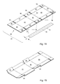
- Figs. 1A to 1E are used to generally describe an embodiment of an assembly 30 according to the invention of a tape 74 and a blank 40 is shown schematically in views in perspective of various stages of folding a box from the blank 40.
- the tape 74 has a breadth B and is in this embodiment integrally provided with tear means, such as a tear strip 75. In other embodiments (not shown) the tape may alternatively be free from tear means.
- the blank 40 has a thickness T, and in this embodiment is manufactured from card board.
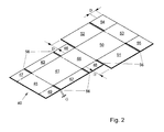
- the blank 40 (see Fig. 1A ) has a rectangular bottom panel 41, rectangular first and second side panels 42, 43, respectively, and rectangular first and second end panels 44, 45, respectively, joined to the bottom panel 41. Rectangular first and second corner panels 46, 48, respectively, are joined to the first end panel 44. Furthermore, rectangular third and fourth corner panels 47, 49, respectively, are joined to the second end panel 45. A rectangular top panel 50 is joined to the first end panel 44, such that it is positioned at the side of the first end panel 44 opposite to the side where the bottom panel 41 is joined to the first end panel.
- the blank 40 furthermore comprises rectangular first and second top side panels 51, 52, respectively, joined to the top panel 50, a rectangular top end panel 53 joined to the top panel 50 and, optional, rectangular first and second top corner panels 54, 55, respectively joined to the top end panel 53.
- Panels which are directly joining each other are joined by means of folding lines, such as the first end panel 44 and the top panel 50 which are joined by lid folding line 60.
- Each folding line can consist of a single, double or triple score lines. Please note that for sake of clarity only the lid folding line has been provided with a reference number.
- Neighbouring panels which are indirectly joined to each other, such as first side panel 42 and second corner panel 48, are spaced by a cut-out 56.
- the cut-outs 56 between the respective corner panels and the adjoining side panels each have a length G (measured in the longitudinal direction of the blank 40) which in the shown embodiments amounts to T [shown in the figures is appr.
- the dimensions of the respective panels will be further discussed with reference to the embodiments shown in Figures 5 and 6 .
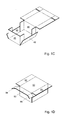
- Figures 1A - 1F the different stages of folding of the blank 40 is shown in which in Fig. 1B to 1E only the blank 40 is shown for clarity, i.e. the tape is not shown.
- Figure 1A shows the blank 40 in its flat position.
- Figure 1B the corner panels 46, 47, 48, 49 are shown partly folded upwards. Thereafter first the end panels 44, 45 are folded upwards and then the side panels 42, 43 are folded upwards. In this situation, shown in Figure 1C the end panels 44, 45 have been erected. Thereafter the top panel 50 is folded over, and the top corner panels 54, 55 are partly folded downwards as shown in Figure 1D .
- top end panel 53 and subsequently the top side panels 51, 52 are folded downwards obtaining the custom sized, unsealed box as indicated in Figure 1E .
- a first seam 81 is formed between the abutting first side panel 42 and first top side panel 51
- a second seam 82 is formed by the free edge of the top end panel 53
- a third seam is formed between the abutting second side panel 43 and second top side panel 52.
- these seams are formed on the external surface of the folded box.
- box seam which can be seen as a single seam which extends around the box at a single vertical height from the bottom which is at least equal to 1 ⁇ 2B, i.e. half the breadth of the tape.
- the width of the side panels (42, 43, 51 and 52) relates to the height of the box, in order to obtain a box that has seams along three exterior sides of the box, at a constant height with respect to the bottom plane of the assembled box, in which said height is such that the ease of closing and opening of the box are improved while the risk of untimely opening is reduced.
- FIG 2 an alternative embodiment of a blank in accordance with the invention is shown in perspective.
- the width of the top side panels 51, 52 is increased with a value D
- the width and length of the top corner panels 54, 55 are increased with the value D
- the length of the top end panel 53 is increased with the value D.
- the other dimensions remain unchanged.
- FIG 3 a further alternative embodiment of a blank in accordance with the invention is shown in perspective.
- the width of the side panels 42, 43 and the width of the corner panels 46, 47, 48, 49 are increased by the value D.
- the other dimensions remain unchanged.
- FIGs. 4A to 4D schematically show possible manners of sealing a box 80 with tape 74.
- first end panel 44 is indicated which end panel 44 after folding does not comprise a seam and thus need not necessarily be provided with tape 74, as indicated in Figures 4C and 4D without detriment to the seal of the box. It is thus not necessary to completely surround the box by tape.
- the arrow in the drawings is indicative of the direction in which the tape is applied, but is not compulsory.
- the tape has been depicted at a distance from the panels of the box, but it will be clear to a person skilled in the art, that the tape is attached onto the panels.
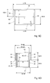
- FIGs. 5A and 5B a further embodiment of a blank in accordance with the invention is schematically shown in which after folding the side panels about each other.
- Figures 5A and 5B represent one and the same embodiment of a blank (apart from the different use of folding lines, as will be discussed below), but for clarity reasons in Fig. 5A only the length dimensions and in Fig. 5B only the width dimensions are indicated.
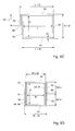
- Figs. 5C and 5D side views in cross-section and in Fig. 5E a top view in cross section of a box erected from the blank shown in Figs. 5A /B is schematically shown in cross-section.
- L is the inside length of the box
- W is the inside width of the box
- H is the inside height of the box.
- the length dimensions are measured in longitudinal direction of the blank and the width dimensions are measured in lateral direction of the blank.
- the blank has a thickness T (indicated in Fig. 5C ) and comprises a rectangular bottom panel 41.
- a first rectangular side panel 42 is joined to a first side of the rectangular bottom panel 41 and a second rectangular side panel 43 is joined to a second side of the rectangular bottom panel 41 opposite the first side thereof.
- a first rectangular end panel 44 is joined to a first end of the bottom panel 41 and a second rectangular end panel 45 is joined to a second end of the bottom panel 41 opposite the first end of the rectangular bottom panel 41. Furthermore a first rectangular corner panel 46 is joined to a first side of the first end panel 44 and a second rectangular corner panel 48 is joined to a second side of the first end panel 44 opposite the first side thereof. Furthermore, a third rectangular corner panel 47 is joined to a first side of the second end panel 45 and a fourth rectangular corner panel 49 is joined to a second side of the second end panel 45 opposite the first side thereof.
- a rectangular top panel 50 is joined to the first the end panel 44 such that it is arranged at the side of the first end panel 44 opposite to the side where the bottom panel 41 is joined to the first end panel 44.
- a first rectangular top side panel 51 is joined to a first side of the top panel 50 and a second rectangular top side panel 52 is joined to a second side of the top panel 50 opposite the first side thereof.
- a rectangular top end panel 53 is joined to the top panel 50 such that it is arranged at the side of the top panel 50 opposite to the side where the first end panel 44 is joined to the top panel 50.
- the tolerance t has a value equal to the thickness T of the blank, but in dependence of amongst other things the stiffness of the material of the blank the tolerance t can have any value up to 2T, i.e. two times the thickness of the blank.
- the rectangular bottom panel 41 has a length L + 2t and a width W + 4t.
- the rectangular side panels 42, 43 each have a length of about L + 2t and a width of H1 + t.
- the rectangular end panels 44, 45 each have a width W + 2t, the first end panel 44 having a length of H + 2t and the second end panel 45 having a length of H + t.
- the rectangular top panel 50 has a length L + 3t and a width W + 4t.
- the rectangular top side panels 51, 52 has a length of about L + 3t (meaning that the length can also be slightly smaller) and a width of H2 + t.
- the rectangular top end panel 53 has a length of H2 + t and a width between W + 2t and W + 4t.
- H1 or H2 equals 1 ⁇ 2H + D
- after folding the box an overlap of D between panels is created which overlap improves protection of items packaged within the box.
- H - H1 and/or H - H2 are equal to or greater than 1 cm, preferably 2 cm, most preferably 3 cm.
- L is greater than or equal to 1 ⁇ 2H.
- Fig. 5A an embodiment is indicated in which the longitudinal folding lines comprise two parallel score lines which are spaced at a distance t" from each other, which distance in the shown embodiments equals T, but which distance t" in other embodiments could have any value up between T and 3T and in which the lateral folding lines consists of a single score line.
- all the folding lines consist of single score lines, but the longitudinal score lines are offset relative to one another with a distance t"' as indicated in the Figure, which distance t"' in the shown embodiments equals T, but in other embodiments could have any value up between T and 3T.
- FIGs. 6A and 6B a further embodiment of a blank in accordance with the invention is schematically shown in which after folding the side panels abut each other.
- Figures 6A and 6B represent one and the same embodiment of a blank (apart from the different use of folding lines, as will be discussed below), but for clarity reasons in Fig. 6A only the length dimensions and in Fig. 6B only the width dimensions are indicated.
- Figs. 6C and 6D side views in cross-section and in Fig. 6E a top view in cross-section of a box erected from the blank shown in Figs. 6A /B is schematically shown in cross-section.
- L is the inside length of the box
- W is the inside width of the box
- H is the inside height of the box.
- the length dimensions are measured in longitudinal direction of the blank and the width dimensions are measured in lateral direction of the blank.
- the blank has a thickness T (indicated in Fig. 6C ) and comprises a rectangular bottom panel 41.
- a first rectangular side panel 42 is joined to a first side of the rectangular bottom panel 41 and a second rectangular side panel 43 is joined to a second side of the rectangular bottom panel 41 opposite the first side thereof.
- a first rectangular end panel 44 is joined to a first end of the bottom panel 41 and a second rectangular end panel 45 is joined to a second end of the bottom panel 41 opposite the first end of the rectangular bottom panel 41.
- a first rectangular corner panel 46 is joined to a first side of the first end panel 44 and a second rectangular corner panel 48 is joined to a second side of the first end panel 44 opposite the first side thereof.
- a third rectangular corner panel 47 is joined to a first side of the second end panel 45 and a fourth rectangular corner panel 49 is joined to a second side of the second end panel 45 opposite the first side thereof.
- a rectangular top panel 50 is joined to the first the end panel 44 such that it is arranged at the side of the first end panel 44 opposite to the side where the bottom panel 41 is joined to the first end panel 44.
- a first rectangular top side panel 51 is joined to a first side of the top panel 50 and a second rectangular top side panel 52 is joined to a second side of the top panel 50 opposite the first side thereof. Furthermore, a rectangular top end panel 53 is joined to the top panel 50 such that it is arranged at the side of the top panel 50 opposite to the side where the first end panel 44 is joined to the top panel 50.
- the blank according to Figs. 6 further comprises a first rectangular top corner panel 54 joined to a first side of the top end panel 53 and a second rectangular top corner panel 54 joined to a second side of the top end panel 53 opposite the first side thereof.
- the rectangular bottom panel 41 has a length L + 2t and a width W + 4t.
- the rectangular side panels 42, 43 each have a length of about L + 2t (meaning that the dimension can also be slightly smaller) and a width of H1 + t.
- the rectangular end panels 44, 45 each have a width W + 2t.
- the first end panel 44 has a length of H + 2t, while the second end panel 45 has a length of H + t.
- the rectangular top panel 50 has a length L + 3t and a width between W + 4t and W + 6t.
- the rectangular top side panels 51, 52 have a length of about L + 3t (meaning that the dimension can also be slightly smaller) and a width between H2 and H2 + t.
- the rectangular top end panel 53 has a length of about H2 (meaning that the dimension can also be slightly smaller) and a width between W + 2t and W + 4t.
- the rectangular top corner panels 54, 55 each have a length of about H2 and a width between H2 and H2 + 2t.
- H1 or H2 equals 1 ⁇ 2H + D
- after folding the box an overlap of D between panels is created which overlap improves protection of items packaged within the box.
- H - H1 and/or H - H2 are equal to or greater than 2 cm, preferably 3 cm.
- L is greater than or equal to 1 ⁇ 2H. This is preferred to make the corner panels 46, 47, 48 and 49, and if present, the top corner panels 54 and 55, fit within the box without requiring additional folds.
- Fig. 6A an embodiment is indicated in which the longitudinal folding lines comprise two parallel score lines which are spaced at a distance t from each other, and in which the lateral folding lines consists of a single score line.
- the longitudinal folding lines comprise two parallel score lines which are spaced at a distance t from each other, and in which the lateral folding lines consists of a single score line.
- all the folding lines consist of single score lines, but the longitudinal score lines are offset relative to one another as indicated in the Figure.
Landscapes
- Engineering & Computer Science (AREA)
- Mechanical Engineering (AREA)
- Cartons (AREA)
Abstract
Description
- The invention relates to an assembly of a blank for a box and a tape used for sealing the box, said tape having a breadth B, said blank having a thickness T and a rectangular bottom panel, a first rectangular side panel joined to a first side of the rectangular bottom panel, a second rectangular side panel joined to a second side of the rectangular bottom panel opposite the first side thereof, a first rectangular end panel joined to a first end of the bottom panel, a second rectangular end panel joined to a second end of the bottom panel opposite the first end of the rectangular bottom panel, a first rectangular corner panel joined to a first side of the first end panel, a second rectangular corner panel joined to a second side of the first end panel opposite the first side thereof, a third rectangular corner panel joined to a first side of the second end panel, a fourth rectangular corner panel joined to a second side of the second end panel opposite the first side thereof, a rectangular top panel joined to the first the end panel such that it is arranged at the side of the first end panel opposite to the side where the bottom panel is joined to the first end panel, a first rectangular top side panel joined to a first side of the top panel, a second rectangular top side panel joined to a second side of the top panel opposite the first side thereof, and a rectangular top end panel joined to the top panel such that it is arranged at the side of the top panel opposite to the side where the first end panel is joined to the top panel. Such a layout of a blank is known as the International fibreboard case code, also called the FEFCO-ESBO code 11th Edition, 2007, number 0410 M/A. From such a blank a box for packaging items can be erected which box is sealed by attaching tape over the seam between respective panels or by using glue.
- Drawbacks of the known assembly and blank are that sealing the box formed out of said known blank by using tape is relatively difficult to perform and in some cases during transport of the box the tape tears resulting in the unwanted opening of the erected box. A further drawback of the known blank is that it is relatively complicated to use for automated packaging of articles.
- It is amongst other things an object of the invention to provide an alternative assembly of a blank for a box and a tape. It is a further object of the invention to provide an assembly of a blank for a box and a tape from which a box can be formed which can relatively easily be sealed by means of the tape. It is a further object of the invention to provide an assembly of a blank for a box and a tape from which a box can be formed which when sealed by means of the tape can be transported with a relative low risk of unwanted opening. Another object of the invention is to provide a blank for a box from which relatively easily a box can be folded around articles to be packaged in an automated way.
- According to the invention at least one of these objects is achieved by providing an assembly of a blank for a box and a tape used for sealing the box, said tape having a breadth B, said blank having a thickness T and a rectangular bottom panel, a first rectangular side panel joined to a first side of the rectangular bottom panel, a second rectangular side panel joined to a second side of the rectangular bottom panel opposite the first side thereof, a first rectangular end panel joined to a first end of the bottom panel, a second rectangular end panel joined to a second end of the bottom panel opposite the first end of the rectangular bottom panel, a first rectangular corner panel joined to a first side of the first end panel, a second rectangular corner panel joined to a second side of the first end panel opposite the first side thereof, a third rectangular corner panel joined to a first side of the second end panel, a fourth rectangular corner panel joined to a second side of the second end panel opposite the first side thereof, a rectangular top panel joined to the first the end panel such that it is arranged at the side of the first end panel opposite to the side where the bottom panel is joined to the first end panel, a first rectangular top side panel joined to a first side of the top panel, a second rectangular top side panel joined to a second side of the top panel) opposite the first side thereof, and a rectangular top end panel joined to the top panel such that it is arranged at the side of the top panel opposite to the side where the first end panel is joined to the top panel, the rectangular bottom panel having a length of about L + 2t and a width of about W + 4t, the rectangular side panels each having a length ranging from about L to about L + 2t and a width of about H1 + t, the rectangular end panels each having a width of about W + 2t, the first rectangular end panel having a length of about H + 2t, the second rectangular end panel having a length of about H + t, the rectangular top panel having a length of about L + 3t and a width of about W + 4t, the rectangular top side panels having a length ranging from about L + t to about L + 3t and a width of about H2 + t, the rectangular top end panel having a length of about H2 + t and a width between about W + 2t and about W + 4t, wherein L ≥ H1, L ≥ H2, and H - H1 ≥ ½B and/or H - H2 ≥ ½B. Preferably t is a tolerance value satisfying the relation 0 ≤ t ≤ 2T defining a tolerance with regard to the height, width and length of the panels of the blank, which dimensions due to the tolerance value may deviate a small amount depending on the material of which the blank is made and taking account of cutting, creasing and folding properties. In particular in case the material is relatively thick compared to the box size (typically when the thickness is more than 1% of the length, width or height of the box)it is preferred that t is approximately equal to T, i.e. the thickness of the blank.The invention is based on the insight that the drawbacks of the known assembly and blank mentioned above are at least partly the result of the fact that the seam of a box folded from the blank is situated at an edge of the box. Sealing this box at said edge by tape requires that the tape - if provided in a direction parallel to the edge - has to be folded around the edge, or - in case the tape is applied transverse to the extending direction of the edge - a plurality of pieces of tape has to be applied next to each other. In both cases the application of tape to seal the box is relatively complex, which is especially a disadvantage in case of automated sealing. Furthermore, since during handling and transport edges of a box formed out of the known blank are most prone to impact, in some cases the tape may tear during transport or handling of the box resulting in the unwanted opening of the erected box. Especially when the seam of the box folded from the known blank is situated at the bottom, tearing of the tape can occur easily. In the assembly in accordance with the invention H - H1 ≥ ½B and/or H - H2 ≥ ½B, such that after folding of the box the seam of the box is positioned at a distance of at least ½B from the edge of the box. In addition a box can be obtained in which the horizontal seams are neatly arranged along one line around the external contour of the box, in a plane substantially parallel to the bottom and top plane of the assembled box. This makes it possible to easily apply a tape at least approximately centered with respect to the seam in a direction parallel to the seam, since the tape can be applied completely in a flat arrangement. Furthermore, the sealing tape does not extend over the top or bottom edges of the erected box, making it less prone to impact and tear and wear during handling and transport. Key in the invention is that the width of the side panels relates to the height of the box, in order to obtain a box that has seams along three exterior sides of the box, at a constant height with respect to the bottom plane of the assembled box, in which said height is such that the ease of closing and opening of the box are improved while the risk of untimely opening is reduced.
- According to a further aspect of the invention at least one of the objects identified above is achieved by providing an assembly of a blank for a box and a tape used for sealing the box, said tape having a breadth B, said blank having a thickness T and a rectangular bottom panel, a first rectangular side panel joined to a first side of the rectangular bottom panel, a second rectangular side panel joined to a second side of the rectangular bottom panel opposite the first side thereof, a first rectangular end panel joined to a first end of the bottom panel, a second rectangular end panel joined to a second end of the bottom panel opposite the first end of the rectangular bottom panel, a first rectangular corner panel joined to a first side of the first end panel, a second rectangular corner panel joined to a second side of the first end panel opposite the first side thereof, a third rectangular corner panel joined to a first side of the second end panel, a fourth rectangular corner panel joined to a second side of the second end panel opposite the first side thereof, a rectangular top panel joined to the first the end panel such that it is arranged at the side of the first end panel opposite to the side where the bottom panel is joined to the first end panel, a first rectangular top side panel joined to a first side of the top panel, a second rectangular top side panel joined to a second side of the top panel opposite the first side thereof, and a rectangular top end panel joined to the top panel such that it is arranged at the side of the top panel opposite to the side where the first end panel is joined to the top panel, the rectangular bottom panel having a length of about L + 2t and a width of about W + 4t, the rectangular side panels each having a length ranging from about L to about L + 2t and a width of about H1 + t, the rectangular end panels each having a width of about W + 2t, the first rectangular end panel having a length of about H + 2t, the second rectangular end panel having a length of about H + t, the rectangular top panel having a length of about L + 3t and a width between about W + 4t and about W + 6t, the rectangular top side panels having a length ranging from about L + t to about L + 3t and a width between about H2 and about H2 + t, the rectangular top end panel having a length of about H2 + t and a width between about W + 2t and about W + 4t, said blank further having a first rectangular top corner panel joined to a first side of the top end panel and a second rectangular top corner panel joined to a second side of the top end panel opposite the first side thereof, the rectangular top corner panels each having a length of about H2 and a width between about H2 and about H2 + 2t, wherein L ≥ H1, L ≥ H2, and H - H1 ≥ ½B and/or H - H2 ≥ ½B.
- In an embodiment of an assembly according to the invention the rectangular corner panels each have a length of about H. Preferably the rectangular corner panels each have a width of about H1 + 2t. Such a length of the corner panels is advantageous since, when folding them at the inside of the box, the height equals the internal height of the box, so that these corner panels act as a support between the bottom and top panel and thus give additional strength to the box which is beneficial during the assembly of the box, especially when this is done in an automated way, and which is also beneficial for handling the assembled box.
- In an advantageous embodiment of an assembly according to the invention H1 = H2. In this manner the blank can be manufactured easily since the circumference of the complete blank is at least substantially rectangular. In a preferred embodiment then H1 = H2 = ½H, such that it is possible to fold the blank in such a manner that the free edges of the side panels and the free edge of the respective top side panels are abutting each other or - depending on tolerances due to cutting and folding - are situated at a small distance from each other, such that after application of the tape the tapes lies in one flat surface upon the side panels. In an alternative embodiment H1=H2=½H+D, such that after folding the respective side panels overlap each other with a distance 2D, leading to an improvement of the protection of items packaged within the box.
- In an alternative embodiment of an assembly according to the invention either H1=½H+D or H2=½H+D, such that after folding the respective side panels overlap each other with a distance D. This provides an improvement of the protection of items packaged within the box, but the circumference of the complete blank is not rectangular any more, which could lead to additional steps of manufacturing the blank.
- In an advantageous embodiment of an assembly according to the invention D < 6 cm, preferably D is at least about 1 cm, most preferably at least about 3 cm. In this manner protection of items packaged within the box is improved while using a relatively low amount of material for manufacturing the blank. Furthermore since the top side panels overlap the side panels with an amount of D or 2D it is ensured that opening of the box by breaking the tape, e.g. with a knife, does not damage the items packaged inside the box. Please note, that also with the overlap the seam of the box which is to be sealed by the tape, is still positioned at a distance of at least ½B from the top and bottom edges of the box.
- In a further embodiment of an assembly according to the invention, wherein the blank is made of cardboard having a thickness T and wherein respective panels of the blank which are directly joined to each other are joined by folding lines and wherein indirectly joined neighbouring panels are separated by cut-outs, the cut-outs have a length G (measured in longitudinal direction of the blank) with a value ranging between 0 and about 4T, preferably having a value of about 2T. For relatively thin and flexible blank material, the cut-out length may be 0, which simplifies the cutting process and limits the amount of generated waste material, in other cases wider cut-outs, up to 4T may be preferred to ease automated manufacturing of the box from the blank. Most preferably the cut-out length is about 2T, in this manner sufficient material is cut out during manufacturing of the blank, which makes it possible to correctly fold the blank into a box without compromising the blank too much to obtain a strong box.
- It should be understood that the most advantageous embodiment can differ from situation to situation, depending on the type of products to be packaged, on the desired level of protection for the items in the box, on the sizes of the box, the thickness and stiffness of the blank material, automation aspects and customer preferences.
- In case the material is relatively stiff (e.g. due to its thickness) it is preferred that each of the folding lines connecting neighboring panels are formed of a number of parallel score lines, preferably two or three parallel score lines, which are spaced at a mutual distance of t", so that it is possible to compensate for this stiffness and for possible tolerances in dimensions and thickness of the material from which the blank is manufactured. In addition or alternatively it is possible to realize such compensation in that the folding lines between separate panels are staggered with respect to each other, i.e. are not in line with each other. For example, the folding line between the bottom panel and the second side panel is not in line with the folding line between the first end panel and the first corner panel, but these folding lines have an offset t"'. The distance t" between the score lines and the offset t"' each preferably have a value in the range of T to 3T. Preferred values of t" depend on the stiffness and/or thickness of the blank material and possibly on the dimensions of the box to be assembled; for two parallel score lines a mutual distance between about T and about 2T is preferred and for three parallel score lines a mutual distance of about T is preferred.
- In a still further embodiment of an assembly according to the invention the blank is made of a single piece of board having a substantially uniform thickness of 1 cm or less, and preferably a thickness less than 0.5 cm.
- In a further embodiment of an assembly according to the invention the blank has a length of about 2L + 2.5 H + 9t and a width of about W + H + 6t, wherein L, W and H are the inside dimensions of a box after folding it from the blank and wherein 0 ≤ t ≤ 2T, wherein T is the thickness of the blank.
- In an alternative embodiment of an assembly according to the invention providing a box with an overlap between respective panels the blank has a length of about 2L + 2.5 H + 2D + 9t and a width of about W + H + 2D + 6t, wherein L, W and H are the inside dimensions of a box after folding it from the blank and wherein 0 ≤ t ≤ 2T, wherein T is the thickness of the blank.
- In a particularly advantageous embodiment of an assembly according to the invention, the tape integrally comprises tear means. Since in accordance with the invention the seam of the box (after proper folding) is situated at a single vertical height from the bottom, it is possible to easily apply a tape around the box at a reproducible defined position. In this manner a sealing tape integrally comprising tear means can be applied to the box in a manner that it is extremely user friendly to open the box, by simply tearing the tear means, such that the seam is exposed to be manually opened by the user without much effort. Although a single tape surrounding the entire box can be used to seal the box, it is in alternative embodiments possible to use two or more pieces of tape to seal the box. In addition these tapes need not necessarily surround the box completely.
- The invention further relates to a blank for an assembly according to the invention.
- The invention further relates to a box formed from any one of the embodiments of an assembly as described above, wherein L is the inside length of the box, W is the inside width of the box and H is the inside height of the box, the box being folded such from the blank that the only seams substantially parallel to the bottom and top plane are a seam for attaching the first side panel to the first top side panel, a seam for attaching the second side panel to the second top side panel, and a seam for attaching the top end panel to the second end panel; wherein said seams are formed on an external surface of the box and are situated at a same distance from the bottom panel, said distance being larger than or equal to ½B.
- The invention is further based on the insight that a box can be formed out of a blank for the inventive assembly wherein the box is sealed by other means than by tape, such as by glue or by wrapping, such as foil wrapping or shrink wrapping.
- The invention further relates to a blank, preferably for a box according to the invention, said blank having a thickness T and a rectangular bottom panel, a first rectangular side panel joined to a first side of the rectangular bottom panel, a second rectangular side panel joined to a second side of the rectangular bottom panel opposite the first side thereof, a first rectangular end panel joined to a first end of the bottom panel, a second rectangular end panel joined to a second end of the bottom panel opposite the first end of the rectangular bottom panel, a first rectangular corner panel joined to a first side of the first end panel, a second rectangular corner panel joined to a second side of the first end panel opposite the first side thereof, a third rectangular corner panel joined to a first side of the second end panel, a fourth rectangular corner panel joined to a second side of the second end panel opposite the first side thereof, a rectangular top panel joined to the first the end panel such that it is arranged at the side of the first end panel opposite to the side where the bottom panel is joined to the first end panel, a first rectangular top side panel joined to a first side of the top panel, a second rectangular top side panel joined to a second side of the top panel opposite the first side thereof, and a rectangular top end panel joined to the top panel such that it is arranged at the side of the top panel opposite to the side where the first end panel is joined to the top panel, the rectangular bottom panel having a length of about L + 2t and a width of about W + 4t, the rectangular side panels each having a length ranging from about L to about L + 2t and a width of about H1 + t, the rectangular end panels each having a width of about W + 2t, the first end panel having a length of about H + 2t, the second end panel having a length of about H + t, the rectangular top panel having a length of about L + 3t and a width of about W + 4t, the rectangular top side panels having a length ranging from about L + t to about L + 3t and a width of about H2 + t, the rectangular top end panel having a length of about H2 + t and a width between about W + 2t and about W + 4t, wherein H1 = H2 = ½H, and wherein L ≥ ½H.
- The invention even further relates to a blank, preferably for a box according to the invention, said blank having a thickness T and a rectangular bottom panel, a first rectangular side panel joined to a first side of the rectangular bottom panel, a second rectangular side panel joined to a second side of the rectangular bottom panel opposite the first side thereof, a first rectangular end panel joined to a first end of the bottom panel, a second rectangular end panel joined to a second end of the bottom panel opposite the first end of the rectangular bottom panel, a first rectangular corner panel joined to a first side of the first end panel, a second rectangular corner panel joined to a second side of the first end panel opposite the first side thereof, a third rectangular corner panel joined to a first side of the second end panel, a fourth rectangular corner panel joined to a second side of the second end panel opposite the first side thereof, a rectangular top panel joined to the first the end panel such that it is arranged at the side of the first end panel opposite to the side where the bottom panel is joined to the first end panel, a first rectangular top side panel joined to a first side of the top panel, a second rectangular top side panel joined to a second side of the top panel opposite the first side thereof, and a rectangular top end panel joined to the top panel such that it is arranged at the side of the top panel opposite to the side where the first end panel is joined to the top panel, the rectangular bottom panel having a length of about L + 2t and a width of about W + 4t, the rectangular side panels each having a length ranging from about L to about L + 2t and a width of about H1 + t, the rectangular end panels each having a width of about W + 2t, the first end panel having a length of about H + 2t, the second end panel having a length of about H + t, the rectangular top panel having a length of about L + 3t and a width of about W + 4t, the rectangular top side panels having a length ranging from about L + t to about L + 3t and a width of about H2 + t, the rectangular top end panel having a length of about H2 + t and a width between about W + 2t and about W + 4t, wherein H1 = ½H and H2 = ½H + D, and wherein D < ½H and L ≥ ½H.
- The invention further relates to a blank, preferably for a box according to the invention, said blank having a thickness T and a rectangular bottom panel, a first rectangular side panel joined to a first side of the rectangular bottom panel, a second rectangular side panel joined to a second side of the rectangular bottom panel opposite the first side thereof, a first rectangular end panel joined to a first end of the bottom panel, a second rectangular end panel joined to a second end of the bottom panel opposite the first end of the rectangular bottom panel, a first rectangular corner panel joined to a first side of the first end panel, a second rectangular corner panel joined to a second side of the first end panel opposite the first side thereof, a third rectangular corner panel joined to a first side of the second end panel, a fourth rectangular corner panel joined to a second side of the second end panel opposite the first side thereof, a rectangular top panel joined to the first the end panel such that it is arranged at the side of the first end panel opposite to the side where the bottom panel is joined to the first end panel, a first rectangular top side panel joined to a first side of the top panel, a second rectangular top side panel joined to a second side of the top panel opposite the first side thereof, and a rectangular top end panel joined to the top panel such that it is arranged at the side of the top panel opposite to the side where the first end panel is joined to the top panel, the rectangular bottom panel having a length of about L + 2t and a width of about W + 4t, the rectangular side panels each having a length ranging from about L to about L + 2t and a width of about H1 + t, the rectangular end panels each having a width of about W + 2t, the first end panel having a length of about H + 2t, the second end panel having a length of about H + t, the rectangular top panel having a length of about L + 3t and a width of about W + 4t, the rectangular top side panels having a length ranging from about L + t to about L + 3t and a width of about H2 + t, the rectangular top end panel having a length of about H2 + t and a width between about W + 2t and about W + 4t, wherein H2 = ½H and H1 = ½H + D, and wherein D < ½H and L ≥ ½H.
- The invention still further relates to a blank, preferably for a box according to the invention, said blank having a thickness T and a rectangular bottom panel, a first rectangular side panel joined to a first side of the rectangular bottom panel, a second rectangular side panel joined to a second side of the rectangular bottom panel opposite the first side thereof, a first rectangular end panel joined to a first end of the bottom panel, a second rectangular end panel joined to a second end of the bottom panel opposite the first end of the rectangular bottom panel, a first rectangular corner panel joined to a first side of the first end panel, a second rectangular corner panel joined to a second side of the first end panel opposite the first side thereof, a third rectangular corner panel joined to a first side of the second end panel, a fourth rectangular corner panel joined to a second side of the second end panel opposite the first side thereof, a rectangular top panel joined to the first the end panel such that it is arranged at the side of the first end panel opposite to the side where the bottom panel is joined to the first end panel, a first rectangular top side panel joined to a first side of the top panel, a second rectangular top side panel joined to a second side of the top panel opposite the first side thereof, and a rectangular top end panel joined to the top panel such that it is arranged at the side of the top panel opposite to the side where the first end panel is joined to the top panel, the rectangular bottom panel having a length of about L + 2t and a width of about W + 4t, the rectangular side panels each having a length ranging from about L to about L + 2t and a width of about H1 + t, the rectangular end panels each having a width of about W + 2t, the first end panel having a length of about H + 2t, the second end panel having a length of about H + t, the rectangular top panel having a length of about L + 3t and a width of about W + 4t, the rectangular top side panels having a length ranging from about L + t to about L + 3t and a width of about H2 + t, the rectangular top end panel having a length of about H2 + t and a width between about W + 2t and about W + 4t, wherein H1=H2=½H+D, and wherein D < ½H and L ≥ ½H.
- The invention even further relates to a blank, preferably for a box according to the invention, said blank having a thickness T and a rectangular bottom panel, a first rectangular side panel joined to a first side of the rectangular bottom panel, a second rectangular side panel joined to a second side of the rectangular bottom panel opposite the first side thereof, a first rectangular end panel joined to a first end of the bottom panel, a second rectangular end panel joined to a second end of the bottom panel opposite the first end of the rectangular bottom panel, a first rectangular corner panel joined to a first side of the first end panel, a second rectangular corner panel joined to a second side of the first end panel opposite the first side thereof, a third rectangular corner panel joined to a first side of the second end panel, a fourth rectangular corner panel joined to a second side of the second end panel opposite the first side thereof, a rectangular top panel joined to the first the end panel such that it is arranged at the side of the first end panel opposite to the side where the bottom panel is joined to the first end panel, a first rectangular top side panel joined to a first side of the top panel, a second rectangular top side panel joined to a second side of the top panel opposite the first side thereof, and a rectangular top end panel joined to the top panel such that it is arranged at the side of the top panel opposite to the side where the first end panel is joined to the top panel, the rectangular bottom panel having a length of about L + 2t and a width of about W + 4t, the rectangular side panels each having a length ranging from about L to about L + 2t and a width of about H1 + t, the rectangular end panels each having a width of about W + 2t, the first end panel having a length of about H + 2t, the second end panel having a length of about H + t, the rectangular top panel having a length of about L + 3t and a width between about W + 4t and about W + 6t, the rectangular top side panels having a length ranging from about L + t to about L + 3t and a width between about H2 and about H2 + t, the rectangular top end panel having a length of about H2 and a width between about W + 2t and about W + 4t, said blank further having a first rectangular top corner panel joined to a first side of the top end panel and a second rectangular top corner panel joined to a second side of the top end panel opposite the first side thereof, the rectangular top corner panels each having a length of about H2 and a width between about H2 and about H2 + 2t, wherein H1 = H2 = ½H, and wherein L ≥ ½H.
- The invention also relates to a blank, preferably for a box according to the invention, said blank having a thickness T and a rectangular bottom panel, a first rectangular side panel joined to a first side of the rectangular bottom panel, a second rectangular side panel joined to a second side of the rectangular bottom panel opposite the first side thereof, a first rectangular end panel joined to a first end of the bottom panel, a second rectangular end panel joined to a second end of the bottom panel opposite the first end of the rectangular bottom panel, a first rectangular corner panel joined to a first side of the first end panel, a second rectangular corner panel joined to a second side of the first end panel opposite the first side thereof, a third rectangular corner panel joined to a first side of the second end panel, a fourth rectangular corner panel joined to a second side of the second end panel opposite the first side thereof, a rectangular top panel joined to the first the end panel such that it is arranged at the side of the first end panel opposite to the side where the bottom panel is joined to the first end panel, a first rectangular top side panel joined to a first side of the top panel, a second rectangular top side panel joined to a second side of the top panel opposite the first side thereof, and a rectangular top end panel joined to the top panel such that it is arranged at the side of the top panel opposite to the side where the first end panel is joined to the top panel, the rectangular bottom panel having a length of about L + 2t and a width of about W + 4t, the rectangular side panels each having a length ranging from about L to about L + 2t and a width of about H1 + t, the rectangular end panels each having a width of about W + 2t, the first end panel having a length of about H + 2t, the second end panel having a length of about H + t, the rectangular top panel having a length of about L + 3t and a width between about W + 4t and about W + 6t, the rectangular top side panels having a length ranging from about L + t to about L + 3t and a width between about H2 and about H2 + t, the rectangular top end panel having a length of about H2 and a width between about W + 2t and about W + 4t, said blank further having a first rectangular top corner panel joined to a first side of the top end panel and a second rectangular top corner panel joined to a second side of the top end panel opposite the first side thereof, the rectangular top corner panels each having a length of about H2 and a width between about H2 about and H2 + 2t, wherein H1 = ½H and H2 = ½H + D, and wherein D < ½H and L ≥ ½H.
- The invention further relates to a blank, preferably for a box according to the invention, said blank having a thickness T and a rectangular bottom panel, a first rectangular side panel joined to a first side of the rectangular bottom panel, a second rectangular side panel joined to a second side of the rectangular bottom panel opposite the first side thereof, a first rectangular end panel joined to a first end of the bottom panel, a second rectangular end panel joined to a second end of the bottom panel opposite the first end of the rectangular bottom panel, a first rectangular corner panel joined to a first side of the first end panel, a second rectangular corner panel joined to a second side of the first end panel opposite the first side thereof, a third rectangular corner panel joined to a first side of the second end panel, a fourth rectangular corner panel joined to a second side of the second end panel opposite the first side thereof, a rectangular top panel joined to the first the end panel such that it is arranged at the side of the first end panel opposite to the side where the bottom panel is joined to the first end panel, a first rectangular top side panel joined to a first side of the top panel, a second rectangular top side panel joined to a second side of the top panel opposite the first side thereof, and a rectangular top end panel joined to the top panel such that it is arranged at the side of the top panel opposite to the side where the first end panel is joined to the top panel, the rectangular bottom panel having a length of about L + 2t and a width of about W + 4t, the rectangular side panels each having a length ranging from about L to about L + 2t and a width of about H1 + t, the rectangular end panels each having a width of about W + 2t, the first end panel having a length of about H + 2t, the second end panel having a length of about H + t, the rectangular top panel having a length of about L + 3t and a width between about W + 4t and about W + 6t, the rectangular top side panels having a length ranging from about L + t to about L + 3t and a width between about H2 and about H2 + t, the rectangular top end panel having a length of about H2 + t and a width between about W + 2t and about W + 4t, said blank further having a first rectangular top corner panel joined to a first side of the top end panel and a second rectangular top corner panel joined to a second side of the top end panel opposite the first side thereof, the rectangular top corner panels each having a length of about H2 and a width between about H2 and about H2 + 2t, wherein H2 = ½H and H1 = ½H + D, and wherein D < ½H and L ≥ ½H.
- The invention still further relates to a blank, preferably for a box according to the invention, said blank having a thickness T and a rectangular bottom panel, a first rectangular side panel joined to a first side of the rectangular bottom panel, a second rectangular side panel joined to a second side of the rectangular bottom panel opposite the first side thereof, a first rectangular end panel joined to a first end of the bottom panel, a second rectangular end panel joined to a second end of the bottom panel opposite the first end of the rectangular bottom panel, a first rectangular corner panel joined to a first side of the first end panel, a second rectangular corner panel joined to a second side of the first end panel opposite the first side thereof, a third rectangular corner panel joined to a first side of the second end panel, a fourth rectangular corner panel joined to a second side of the second end panel opposite the first side thereof, a rectangular top panel joined to the first the end panel such that it is arranged at the side of the first end panel opposite to the side where the bottom panel is joined to the first end panel, a first rectangular top side panel joined to a first side of the top panel, a second rectangular top side panel joined to a second side of the top panel opposite the first side thereof, and a rectangular top end panel joined to the top panel such that it is arranged at the side of the top panel opposite to the side where the first end panel is joined to the top panel, the rectangular bottom panel having a length of about L + 2t and a width of about W + 4t, the rectangular side panels each having a length ranging from about L to about L + 2t and a width of about H1 + t, the rectangular end panels each having a width of about W + 2t, the first end panel having a length of about H + 2t, the second end panel having a length of about H + t, the rectangular top panel having a length of about L + 3t and a width between about W + 4t and about W + 6t, the rectangular top side panels having a length ranging from about L + t to about L + 3t and a width between about H2 and about H2 + t, the rectangular top end panel having a length of about H2 + t and a width between about W + 2t and about W + 4t, said blank further having a first rectangular top corner panel joined to a first side of the top end panel and a second rectangular top corner panel joined to a second side of the top end panel opposite the first side thereof, the rectangular top corner panels each having a length of about H2 and a width between about H2 and about H2 + 2t, wherein H1 = H2 = ½H + D, and wherein D < ½H and L ≥ ½H.
- In addition from such a blank a box can be obtained in which the horizontal seams are neatly arranged along one line around the external contour of the box, in a plane substantially parallel to the bottom and top plane of the assembled box.
- In a preferred embodiment of such a blank for a box according to the invention the rectangular corner panels each have a length of about H. Preferably the rectangular corner panels each have a width of about H1 + 2t. Such a length of the corner panels is advantageous since, when folding them at the inside of the box, the height equals the internal height of the box, so that these corner panels act as a support between the bottom and top panel and thus give additional strength to the box which is beneficial during the assembly of the box, especially when this is done in an automated way, and which is also beneficial for handling the assembled box, since this improves protection of the contents.
- In a further embodiment of a blank according to the invention t is a tolerance value satisfying the relation 0 ≤ t ≤ 2T defining a tolerance with regard to the height, width and length of the panels of the blank, which dimensions due to the tolerance value may deviate a small amount depending on the material of which the blank is made and taking account of cutting, creasing and folding properties. In particular in case the material is relatively thick compared to the box size (typically when the thickness is more than about 1% of the length, width or height of the box) it is preferred that t is approximately equal to T, i.e. the thickness of the blank.
- In advantageous embodiments of respective above described blanks according to the invention D < 6 cm, preferably D is at least about 1 cm, most preferably at least about 3 cm. In this manner protection of items packaged within a box folded from the blanks is improved while using a relatively low amount of material for manufacturing the blank. Furthermore since the top side panels overlap the side panels and the end panel with an amount of D or 2D it is ensured that opening of the box by breaking the tape, e.g. with a knife, does not damage the items packaged inside the box. Please note, that the overlap is chosen such that the seam of the box which is to be sealed, is positioned at a distance (i.e. the values H - H1 and/or H - H2) from the top and bottom edge of the box which is at least 2 cm, and preferably at least 3 cm to prevent that during handling or transport the seam is accidentally and easily caught or grasped which could result in untimely opening of the box.
- In a further embodiment of each of the blanks according to the invention as described above, wherein respective panels of the blank which are directly joined to each other are joined by folding lines and wherein indirectly joined neighbouring panels are separated by cut-outs, the cut-outs have a length G with a value of at most 4T, preferably about 2T. For relatively thin and flexible blank material, the cut-out length may be 0, which simplifies the cutting process and limits the amount of generated waste material, in other cases wider cut-outs, up to 4T may be preferred to ease automated manufacturing of the box from the blank. Most preferably the cut-out length is about 2T, in this manner sufficient material is cut out during manufacturing of the blank, which makes it possible to correctly fold the blank into a box without compromising the blank too much to obtain a strong box.
- In an embodiment of a blank according to the invention the blank is rectangular, which means that, apart from the cut-outs between the side and corner panels, the outside contour of the blank has a rectangular shape. In this manner a blank can be manufactured easily.
- It should be understood that the most advantageous embodiment can differ from situation to situation, depending on the type of products to be packaged, on the desired level of protection for the items in the box, on the sizes of the box, the thickness and stiffness of the blank material, automation aspects and customer preferences.
- In case the material is relatively stiff (e.g. due to its thickness) it is preferred that each of the folding lines connecting neighboring panels are formed of a number of parallel score lines, preferably two or three parallel score lines, which are spaced at a mutual distance of t", so that it is possible to compensate for this stiffness and for possible tolerances in dimensions and thickness of the material from which the blank is manufactured. In addition or alternatively it is possible to realize such compensation in that the folding lines between separate panels are staggered with respect to each other, i.e. are not in line with each other. For example, the folding line between the bottom panel and the second side panel is not in line with the folding line between the first end panel and the first corner panel, but these folding lines have an offset t"'. The distance t" between the score lines and the offset t"' each preferably have a value in the range of T to 3T. Preferred values of t" depend on the stiffness and/or thickness of the blank material and possibly on the dimensions of the box to be assembled; for two parallel score lines a mutual distance between about T and about 2T is preferred and for three parallel score lines a mutual distance of about T is preferred.
- In a still further embodiment of a blank for a box according to the invention the blank is made of a single piece of board having a substantially uniform thickness of 1 cm or less, and preferably a thickness less than 0.5 cm.
- In another embodiment of a blank for a box according to the invention the blank has a length of about 2L + 2.5 H + 9t and a width of about W + H + 6t, wherein L, W and H are the inside dimensions of a box after folding it from the blank and wherein 0 ≤ t ≤ 2T, wherein T is the thickness of the blank.
- In another embodiment of a blank for a box according to the invention in which after erecting a box from the blank there is an overlap between respective panels the blank has a length of about 2L + 2.5 H + 2D + 9t and a width of about W + H +2D + 6t, wherein L, W and H are the inside dimensions of a box after folding it from the blank and wherein 0 ≤ t ≤ 2T, wherein T is the thickness of the blank.
- The invention still further relates to a box folded from a blank according to the invention, wherein the box is folded such from the blank according to the invention that the only seams substantially parallel to the bottom and the top plane are a seam for attaching the first side panel to the first top side panel, a seam for attaching the second side panel to the second top side panel, and a seam for attaching the top end panel to the second end panel are formed on an external surface of the box and that these seams are situated at a same distance from the bottom panel. Preferably, the box comprises a piece of tape attaching respective panels to each other, said piece of tape integrally comprising tear means. In an advantageous embodiment of a box according to the invention, the box comprises a single piece of tape attaching all respective panels to each other.
- To further clarify various aspects of embodiments of the present disclosure and additional features and advantages of the embodiments, a more particular description of various aspects and features will be rendered by reference to specific embodiments thereof which are illustrated in the appended drawings. It is appreciated that these drawings depict only typical embodiments of the disclosure and are therefore not to be considered limiting its scope, nor are the figures necessarily drawn to scale.
- The embodiments herein will be described and explained with additional specificity and detail through the use of the accompanying drawings in which:
-
Figs. 1A to 1E schematically show views in perspective of various stages of folding a box from an assembly of a blank and a tape in accordance with the invention; -
Fig. 1F schematically shows a view in perspective of a box in accordance with the invention; -
Fig.2 schematically shows a perspective view of an alternative embodiment of a blank in accordance with the invention; -
Fig.3 schematically shows a perspective view of a further alternative embodiment of a blank in accordance with the invention; -
Figs. 4A to 4D schematically show possible manners of sealing a box in accordance with the invention with tape; -
Figs. 5A and 5B schematically show a further embodiment of a blank in accordance with the invention in which the side flaps abut each other, in which inFig. 5A the length dimensions and inFig. 5B the width dimensions are indicated; -
Figs. 5C to 5E schematically show views in cross-section of a box erected from the blank shown inFigs. 5A /B; -
Figs. 6A and 6B schematically show a further embodiment of a blank in accordance with the invention in which the side flaps abut each other, in which inFig. 6A the length dimensions and inFig. 6B the width dimensions are indicated; and -
Figs. 6C to 6E schematically show views in cross-section of a box erected from the blank shown inFigs. 6A /B. -
Figs. 1A to 1E are used to generally describe an embodiment of anassembly 30 according to the invention of atape 74 and a blank 40 is shown schematically in views in perspective of various stages of folding a box from the blank 40. Thetape 74 has a breadth B and is in this embodiment integrally provided with tear means, such as atear strip 75. In other embodiments (not shown) the tape may alternatively be free from tear means. The blank 40 has a thickness T, and in this embodiment is manufactured from card board. - The blank 40 (see
Fig. 1A ) has arectangular bottom panel 41, rectangular first andsecond side panels second end panels bottom panel 41. Rectangular first andsecond corner panels first end panel 44. Furthermore, rectangular third andfourth corner panels second end panel 45. A rectangulartop panel 50 is joined to thefirst end panel 44, such that it is positioned at the side of thefirst end panel 44 opposite to the side where thebottom panel 41 is joined to the first end panel. The blank 40 furthermore comprises rectangular first and secondtop side panels top panel 50, a rectangulartop end panel 53 joined to thetop panel 50 and, optional, rectangular first and secondtop corner panels top end panel 53. - Panels which are directly joining each other are joined by means of folding lines, such as the
first end panel 44 and thetop panel 50 which are joined bylid folding line 60. Each folding line can consist of a single, double or triple score lines. Please note that for sake of clarity only the lid folding line has been provided with a reference number. Neighbouring panels which are indirectly joined to each other, such asfirst side panel 42 andsecond corner panel 48, are spaced by a cut-out 56. The cut-outs 56 between the respective corner panels and the adjoining side panels each have a length G (measured in the longitudinal direction of the blank 40) which in the shown embodiments amounts to T [shown in the figures is appr. G=T, although G=2T would be preferred], but which in other embodiments can have any value up to 4T, thus a length which is sufficient for allowing a correct folding of the panels with respect to one another. The dimensions of the respective panels will be further discussed with reference to the embodiments shown inFigures 5 and6 . - In
Figures 1A - 1F the different stages of folding of the blank 40 is shown in which inFig. 1B to 1E only the blank 40 is shown for clarity, i.e. the tape is not shown.Figure 1A shows the blank 40 in its flat position. InFigure 1B thecorner panels end panels side panels Figure 1C theend panels top panel 50 is folded over, and thetop corner panels Figure 1D . Next thetop end panel 53 and subsequently thetop side panels Figure 1E . As a result of the dimensions of the panels as will be discussed with reference toFigures 5 and6 afirst seam 81 is formed between the abuttingfirst side panel 42 and firsttop side panel 51, asecond seam 82 is formed by the free edge of thetop end panel 53, and a third seam (not visible inFigure 1E ) is formed between the abuttingsecond side panel 43 and secondtop side panel 52. As can be seen inFigure 1E these seams are formed on the external surface of the folded box. These three seams form the, what is called here the box seam, which can be seen as a single seam which extends around the box at a single vertical height from the bottom which is at least equal to ½B, i.e. half the breadth of the tape. This makes the application of thesingle tape 74 around the box to seal the box, as shown inFigure 1F , easy, and allows for automating the sealing process. Key in the invention is that the width of the side panels (42, 43, 51 and 52) relates to the height of the box, in order to obtain a box that has seams along three exterior sides of the box, at a constant height with respect to the bottom plane of the assembled box, in which said height is such that the ease of closing and opening of the box are improved while the risk of untimely opening is reduced. - In
Figure 2 an alternative embodiment of a blank in accordance with the invention is shown in perspective. With respect to the blank shown inFigure 1A the following dimensions are different: the width of thetop side panels top corner panels top end panel 53 is increased with the value D. The other dimensions remain unchanged. - In
Figure 3 a further alternative embodiment of a blank in accordance with the invention is shown in perspective. With respect to the blank shown inFigure 1A the following dimensions are different: the width of theside panels corner panels - After folding the blanks according to
Figures 2 and3 an overlap between respective panels is obtained, however the circumference of these blanks is not rectangular. Please note that this overlap between panels improves the protection of items packaged within the box. Also with the overlap which can be obtained in these alternative embodiments the seam of the box which is to be sealed by the tape, is still positioned at a single distance of at least ½B from the edge of the box. In case the box is sealed by means of glue the overlap between respective panels preferably is at least 1 cm to ensure a proper sealing. -
Figs. 4A to 4D schematically show possible manners of sealing abox 80 withtape 74. In these Figuresfirst end panel 44 is indicated whichend panel 44 after folding does not comprise a seam and thus need not necessarily be provided withtape 74, as indicated inFigures 4C and 4D without detriment to the seal of the box. It is thus not necessary to completely surround the box by tape. The arrow in the drawings is indicative of the direction in which the tape is applied, but is not compulsory. In addition for clarity sake the tape has been depicted at a distance from the panels of the box, but it will be clear to a person skilled in the art, that the tape is attached onto the panels. - In
Figs. 5A and 5B a further embodiment of a blank in accordance with the invention is schematically shown in which after folding the side panels about each other. Please note that theFigures 5A and 5B represent one and the same embodiment of a blank (apart from the different use of folding lines, as will be discussed below), but for clarity reasons inFig. 5A only the length dimensions and inFig. 5B only the width dimensions are indicated. InFigs. 5C and 5D side views in cross-section and inFig. 5E a top view in cross section of a box erected from the blank shown inFigs. 5A /B is schematically shown in cross-section. In theseFigures 5C to 5E it is indicated that L is the inside length of the box, W is the inside width of the box and H is the inside height of the box. Please note that the length dimensions are measured in longitudinal direction of the blank and the width dimensions are measured in lateral direction of the blank. As before the blank has a thickness T (indicated inFig. 5C ) and comprises arectangular bottom panel 41. A firstrectangular side panel 42 is joined to a first side of therectangular bottom panel 41 and a secondrectangular side panel 43 is joined to a second side of therectangular bottom panel 41 opposite the first side thereof. A firstrectangular end panel 44 is joined to a first end of thebottom panel 41 and a secondrectangular end panel 45 is joined to a second end of thebottom panel 41 opposite the first end of therectangular bottom panel 41. Furthermore a firstrectangular corner panel 46 is joined to a first side of thefirst end panel 44 and a secondrectangular corner panel 48 is joined to a second side of thefirst end panel 44 opposite the first side thereof. Furthermore, a thirdrectangular corner panel 47 is joined to a first side of thesecond end panel 45 and a fourthrectangular corner panel 49 is joined to a second side of thesecond end panel 45 opposite the first side thereof. In addition, a rectangulartop panel 50 is joined to the first theend panel 44 such that it is arranged at the side of thefirst end panel 44 opposite to the side where thebottom panel 41 is joined to thefirst end panel 44. A first rectangulartop side panel 51 is joined to a first side of thetop panel 50 and a second rectangulartop side panel 52 is joined to a second side of thetop panel 50 opposite the first side thereof. Finally, a rectangulartop end panel 53 is joined to thetop panel 50 such that it is arranged at the side of thetop panel 50 opposite to the side where thefirst end panel 44 is joined to thetop panel 50. - In the shown embodiments the tolerance t has a value equal to the thickness T of the blank, but in dependence of amongst other things the stiffness of the material of the blank the tolerance t can have any value up to 2T, i.e. two times the thickness of the blank.
- As indicated in
Figures 5A and 5B therectangular bottom panel 41 has a length L + 2t and a width W + 4t. Therectangular side panels rectangular end panels first end panel 44 having a length of H + 2t and thesecond end panel 45 having a length of H + t. The rectangulartop panel 50 has a length L + 3t and a width W + 4t. The rectangulartop side panels top end panel 53 has a length of H2 + t and a width between W + 2t and W + 4t. The cut-outs between the respective corner panels and the adjoining side panels each have a length G which in the shown embodiments is about T [shown is G=T, although preferred value is G=2T], but which length G in other embodiments could have any value up to 4T, thus a length which is sufficient for allowing a correct folding of the panels with respect to one another. - In embodiments where the dimensions H1 and H2 are equal (H1 = H2) a rectangular blank as shown in
Figure 1A is obtained. In embodiments where H1 = H2 = ½H after erecting the box the respective panels abut each other as indicated inFig. 1E . In embodiments where H1 = H2 = ½H + D, after folding the box an overlap of 2D between panels is created which overlap improves protection of items packaged within the box. In embodiments where either H1 or H2 equals ½H + D, after folding the box an overlap of D between panels is created which overlap improves protection of items packaged within the box. In the embodiments ofFigs. 5 the values of H - H1 and/or H - H2 are equal to or greater than 1 cm, preferably 2 cm, most preferably 3 cm. Thus also with an overlap the seam of the box which is to be sealed e.g. by tape or glue, is still positioned at a distance of at least 1 cm from the edge of the box. In all these embodiments L is greater than or equal to ½H. - In
Fig. 5A an embodiment is indicated in which the longitudinal folding lines comprise two parallel score lines which are spaced at a distance t" from each other, which distance in the shown embodiments equals T, but which distance t" in other embodiments could have any value up between T and 3T and in which the lateral folding lines consists of a single score line. In the embodiment shown inFig. 5B , all the folding lines consist of single score lines, but the longitudinal score lines are offset relative to one another with a distance t"' as indicated in the Figure, which distance t"' in the shown embodiments equals T, but in other embodiments could have any value up between T and 3T. - In
Figs. 6A and 6B a further embodiment of a blank in accordance with the invention is schematically shown in which after folding the side panels abut each other. Please note that theFigures 6A and 6B represent one and the same embodiment of a blank (apart from the different use of folding lines, as will be discussed below), but for clarity reasons inFig. 6A only the length dimensions and inFig. 6B only the width dimensions are indicated. InFigs. 6C and 6D side views in cross-section and inFig. 6E a top view in cross-section of a box erected from the blank shown inFigs. 6A /B is schematically shown in cross-section. In theseFigures 6C to 6E it is indicated that L is the inside length of the box, W is the inside width of the box and H is the inside height of the box. Please note that the length dimensions are measured in longitudinal direction of the blank and the width dimensions are measured in lateral direction of the blank. As before the blank has a thickness T (indicated inFig. 6C ) and comprises arectangular bottom panel 41. A firstrectangular side panel 42 is joined to a first side of therectangular bottom panel 41 and a secondrectangular side panel 43 is joined to a second side of therectangular bottom panel 41 opposite the first side thereof. A firstrectangular end panel 44 is joined to a first end of thebottom panel 41 and a secondrectangular end panel 45 is joined to a second end of thebottom panel 41 opposite the first end of therectangular bottom panel 41. A firstrectangular corner panel 46 is joined to a first side of thefirst end panel 44 and a secondrectangular corner panel 48 is joined to a second side of thefirst end panel 44 opposite the first side thereof. Furthermore, a thirdrectangular corner panel 47 is joined to a first side of thesecond end panel 45 and a fourthrectangular corner panel 49 is joined to a second side of thesecond end panel 45 opposite the first side thereof. A rectangulartop panel 50 is joined to the first theend panel 44 such that it is arranged at the side of thefirst end panel 44 opposite to the side where thebottom panel 41 is joined to thefirst end panel 44. A first rectangulartop side panel 51 is joined to a first side of thetop panel 50 and a second rectangulartop side panel 52 is joined to a second side of thetop panel 50 opposite the first side thereof. Furthermore, a rectangulartop end panel 53 is joined to thetop panel 50 such that it is arranged at the side of thetop panel 50 opposite to the side where thefirst end panel 44 is joined to thetop panel 50. When compared with the embodiment of the blank shown inFigs. 5 the blank according toFigs. 6 further comprises a first rectangulartop corner panel 54 joined to a first side of thetop end panel 53 and a second rectangulartop corner panel 54 joined to a second side of thetop end panel 53 opposite the first side thereof. - In the embodiment of
Figs. 6A toD therectangular bottom panel 41 has a length L + 2t and a width W + 4t. Therectangular side panels rectangular end panels first end panel 44 has a length of H + 2t, while thesecond end panel 45 has a length of H + t. The rectangulartop panel 50 has a length L + 3t and a width between W + 4t and W + 6t. The rectangulartop side panels top end panel 53 has a length of about H2 (meaning that the dimension can also be slightly smaller) and a width between W + 2t and W + 4t. The rectangulartop corner panels - In particular embodiments of
Figs. 6 the dimensions H1 and H2 are equal (H1 = H2) such that a rectangular blank as shown inFigure 1A is obtained. In embodiments where H1 = H2 = ½H after erecting the box the respective panels abut each other as indicated inFig. 1E . In embodiments where H1 = H2 = ½H + D, after folding the box an overlap of 2D between panels is created which overlap improves protection of items packaged within the box. In embodiments where either H1 or H2 equals ½H + D, after folding the box an overlap of D between panels is created which overlap improves protection of items packaged within the box. In the embodiment ofFigs. 6 the values of H - H1 and/or H - H2 are equal to or greater than 2 cm, preferably 3 cm. Thus also with an overlap the seam of the box which is to be sealed, e.g. by tape or glue, is still positioned at a distance of at least 2 cm from the edge of the box. In all these embodiments L is greater than or equal to ½H. This is preferred to make thecorner panels top corner panels - In
Fig. 6A an embodiment is indicated in which the longitudinal folding lines comprise two parallel score lines which are spaced at a distance t from each other, and in which the lateral folding lines consists of a single score line. In the embodiment shown inFig. 6B , all the folding lines consist of single score lines, but the longitudinal score lines are offset relative to one another as indicated in the Figure.
Claims (26)
- An assembly of a blank for a box and a tape used for sealing the box, said tape having a breadth B, said blank having a thickness T and a rectangular bottom panel (41), a first rectangular side panel (42) joined to a first side of the rectangular bottom panel (41), a second rectangular side panel (43) joined to a second side of the rectangular bottom panel (41) opposite the first side thereof, a first rectangular end panel (44) joined to a first end of the bottom panel (41), a second rectangular end panel (45) joined to a second end of the bottom panel (41) opposite the first end of the rectangular bottom panel (41), a first rectangular corner panel (46) joined to a first side of the first end panel (44), a second rectangular corner panel (48) joined to a second side of the first end panel (44) opposite the first side thereof, a third rectangular corner panel (47) joined to a first side of the second end panel (45), a fourth rectangular corner panel (49) joined to a second side of the second end panel (45) opposite the first side thereof, a rectangular top panel (50) joined to the first the end panel (44) such that it is arranged at the side of the first end panel (44) opposite to the side where the bottom panel (41) is joined to the first end panel (44), a first rectangular top side panel (51) joined to a first side of the top panel (50), a second rectangular top side panel (52) joined to a second side of the top panel (50) opposite the first side thereof, and a rectangular top end panel (53) joined to the top panel (50) such that it is arranged at the side of the top panel (50) opposite to the side where the first end panel (44) is joined to the top panel (50), the rectangular bottom panel (41) having a length of about L + 2t and a width of about W + 4t, the rectangular side panels (42, 43) each having a length ranging from about L to about L + 2t and a width of about H1 + t, the rectangular end panels (44, 45) each having a width of about W + 2t, the first rectangular end panel (44) having a length of about H + 2t, the second rectangular end panel (45) having a length of about H + t, the rectangular top panel (50) having a length of about L + 3t and a width of about W + 4t, the rectangular top side panels (51, 52) having a length ranging from about L + t to about L + 3t and a width of about H2 + t, the rectangular top end panel (53) having a length of about H2 + t and a width between about W + 2t and about W + 4t, wherein L ≥ H1, L ≥ H2, and H - H1 ≥ ½B and/or H - H2 ≥ ½B.
- An assembly of a blank for a box and a tape used for sealing the box, said tape having a breadth B, said blank having a thickness T and a rectangular bottom panel (41), a first rectangular side panel (42) joined to a first side of the rectangular bottom panel (41), a second rectangular side panel (43) joined to a second side of the rectangular bottom panel (41) opposite the first side thereof, a first rectangular end panel (44) joined to a first end of the bottom panel (41), a second rectangular end panel (45) joined to a second end of the bottom panel (41) opposite the first end of the rectangular bottom panel (41), a first rectangular corner panel (46) joined to a first side of the first end panel (44), a second rectangular corner panel (48) joined to a second side of the first end panel (44) opposite the first side thereof, a third rectangular corner panel (47) joined to a first side of the second end panel (45), a fourth rectangular corner panel (49) joined to a second side of the second end panel (45) opposite the first side thereof, a rectangular top panel (50) joined to the first the end panel (44) such that it is arranged at the side of the first end panel (44) opposite to the side where the bottom panel (41) is joined to the first end panel (44), a first rectangular top side panel (51) joined to a first side of the top panel (50), a second rectangular top side panel (52) joined to a second side of the top panel (50) opposite the first side thereof, and a rectangular top end panel (53) joined to the top panel (50) such that it is arranged at the side of the top panel (50) opposite to the side where the first end panel (44) is joined to the top panel (50), the rectangular bottom panel (41) having a length of about L + 2t and a width of about W + 4t, the rectangular side panels (42, 43) each having a length ranging from about L to about L + 2t and a width of about H1 + t, the rectangular end panels (44, 45) each having a width of about W + 2t, the first rectangular end panel (44) having a length of about H + 2t, the second rectangular end panel (45) having a length of about H + t, the rectangular top panel (50) having a length of about L + 3t and a width between about W + 4t and about W + 6t, the rectangular top side panels (51, 52) having a length ranging from about L + t to about L + 3t and a width between about H2 and about H2 + t, the rectangular top end panel (53) having a length of about H2 + t and a width between about W + 2t and about W + 4t, said blank further having a first rectangular top corner panel (54) joined to a first side of the top end panel (53) and a second rectangular top corner panel (55) joined to a second side of the top end panel (53) opposite the first side thereof, the rectangular top corner panels (54, 55) each having a length of about H2 and a width between about H2 and about H2 + 2t, wherein L ≥ H1, L ≥ H2, and H - H1 ≥ ½B and/or H - H2 ≥ ½B.
- An assembly according to claim 1 or 2, wherein the rectangular corner panels (46, 47, 48, 49) each have a length of about H.
- An assembly according to any one of the preceding claims, wherein t is a tolerance value satisfying the relation 0 ≤ t ≤ 2T.
- An assembly according to any one of the preceding claims, wherein H1 = H2.
- An assembly according to claim 5, wherein H1 = H2 = ½H.
- An assembly according to any one of the claims 1 to 4, wherein H2=½H+D or H1=½H+D, such that after folding the respective side panels overlap each other with a distance D, or that H2=½H+D and H1=½H+D, such that after folding the respective side panels overlap each other with a distance 2D.
- An assembly according to claim 7, wherein D < 6 cm, preferably D is at least about 1 cm, and most preferably at least about 3 cm.
- An assembly according to any one of the preceding claims, wherein respective panels of the blank which are directly joined to each other are joined by folding lines, and wherein the folding lines connecting neighboring panels are formed of a number of parallel score lines, preferably two or three parallel score lines, which are spaced at a mutual distance of t", wherein t" has a value in the range of about T to 3T.
- An assembly according to any one of the preceding claims, wherein the tape integrally comprises tear means.
- A blank for an assembly according to any one of the preceding claims.
- A box formed from an assembly according to any one of the claims 1 to 10, wherein L is the inside length of the box, W is the inside width of the box and H is the inside height of the box, the box being folded such from the blank that the only seams substantially parallel to the bottom and top plane are a seam (81) for attaching the first side panel (42) to the first top side panel (51), a seam (83) for attaching the second side panel (43) to the second top side panel (52), and a seam (82) for attaching the top end panel (53) to the second end panel (45); wherein said seams are formed on an external surface of the box and are situated at a same distance from the bottom panel, said distance being larger than or equal to ½B.
- A blank, preferably for a box according to claim 12, said blank having a thickness T and a rectangular bottom panel (41), a first rectangular side panel (42) joined to a first side of the rectangular bottom panel (41), a second rectangular side panel (43) joined to a second side of the rectangular bottom panel (41) opposite the first side thereof, a first rectangular end panel (44) joined to a first end of the bottom panel (41), a second rectangular end panel (45) joined to a second end of the bottom panel (41) opposite the first end of the rectangular bottom panel (41), a first rectangular corner panel (46) joined to a first side of the first end panel (44), a second rectangular corner panel (48) joined to a second side of the first end panel (44) opposite the first side thereof, a third rectangular corner panel (47) joined to a first side of the second end panel (45), a fourth rectangular corner panel (49) joined to a second side of the second end panel (45) opposite the first side thereof, a rectangular top panel (50) joined to the first the end panel (44) such that it is arranged at the side of the first end panel (44) opposite to the side where the bottom panel (41) is joined to the first end panel (44), a first rectangular top side panel (51) joined to a first side of the top panel (50), a second rectangular top side panel (52) joined to a second side of the top panel (50) opposite the first side thereof, and a rectangular top end panel (53) joined to the top panel (50) such that it is arranged at the side of the top panel (50) opposite to the side where the first end panel (44) is joined to the top panel (50), the rectangular bottom panel (41) having a length of about L + 2t and a width of about W + 4t, the rectangular side panels (42, 43) each having a length ranging from about L to about L + 2t and a width of about H1 + t, the rectangular end panels (44, 45) each having a width of about W + 2t, the first end panel (44) having a length of about H + 2t, the second end panel (45) having a length of about H + t, the rectangular top panel (50) having a length of about L + 3t and a width of about W + 4t, the rectangular top side panels (51, 52) having a length ranging from about L + t to about L + 3t and a width of about H2 + t, the rectangular top end panel (53) having a length of about H2 + t and a width between about W + 2t and about W + 4t, wherein H1 = H2 = ½H, and wherein L ≥ ½H.
- A blank, preferably for a box according to claim 12, said blank having a thickness T and a rectangular bottom panel (41), a first rectangular side panel (42) joined to a first side of the rectangular bottom panel (41), a second rectangular side panel (43) joined to a second side of the rectangular bottom panel (41) opposite the first side thereof, a first rectangular end panel (44) joined to a first end of the bottom panel (41), a second rectangular end panel (45) joined to a second end of the bottom panel (41) opposite the first end of the rectangular bottom panel (41), a first rectangular corner panel (46) joined to a first side of the first end panel (44), a second rectangular corner panel (48) joined to a second side of the first end panel (44) opposite the first side thereof, a third rectangular corner panel (47) joined to a first side of the second end panel (45), a fourth rectangular corner panel (49) joined to a second side of the second end panel (45) opposite the first side thereof, a rectangular top panel (50) joined to the first the end panel (44) such that it is arranged at the side of the first end panel (44) opposite to the side where the bottom panel (41) is joined to the first end panel (44), a first rectangular top side panel (51) joined to a first side of the top panel (50), a second rectangular top side panel (52) joined to a second side of the top panel (50) opposite the first side thereof, and a rectangular top end panel (53) joined to the top panel (50) such that it is arranged at the side of the top panel (50) opposite to the side where the first end panel (44) is joined to the top panel (50), the rectangular bottom panel (41) having a length of about L + 2t and a width of about W + 4t, the rectangular side panels (42, 43) each having a length ranging from about L to about L + 2t and a width of about H1 + t, the rectangular end panels (44, 45) each having a width of about W + 2t, the first end panel (44) having a length of about H + 2t, the second end panel (45) having a length of about H + t, the rectangular top panel (50) having a length of about L + 3t and a width of about W + 4t, the rectangular top side panels (51, 52) having a length ranging from about L + t to about L + 3t and a width of about H2 + t, the rectangular top end panel (53) having a length of about H2 + t and a width between about W + 2t and about W + 4t, wherein H1 = H2 = ½H + D, and wherein D < ½H and L ≥ ½H.
- A blank, preferably for a box according to claim 12, said blank having a thickness T and a rectangular bottom panel (41), a first rectangular side panel (42) joined to a first side of the rectangular bottom panel (41), a second rectangular side panel (43) joined to a second side of the rectangular bottom panel (41) opposite the first side thereof, a first rectangular end panel (44) joined to a first end of the bottom panel (41), a second rectangular end panel (45) joined to a second end of the bottom panel (41) opposite the first end of the rectangular bottom panel (41), a first rectangular corner panel (46) joined to a first side of the first end panel (44), a second rectangular corner panel (48) joined to a second side of the first end panel (44) opposite the first side thereof, a third rectangular corner panel (47) joined to a first side of the second end panel (45), a fourth rectangular corner panel (49) joined to a second side of the second end panel (45) opposite the first side thereof, a rectangular top panel (50) joined to the first the end panel (44) such that it is arranged at the side of the first end panel (44) opposite to the side where the bottom panel (41) is joined to the first end panel (44), a first rectangular top side panel (51) joined to a first side of the top panel (50), a second rectangular top side panel (52) joined to a second side of the top panel (50) opposite the first side thereof, and a rectangular top end panel (53) joined to the top panel (50) such that it is arranged at the side of the top panel (50) opposite to the side where the first end panel (44) is joined to the top panel (50), the rectangular bottom panel (41) having a length of about L + 2t and a width of about W + 4t, the rectangular side panels (42, 43) each having a length ranging from about L to about L + 2t and a width of about H1 + t, the rectangular end panels (44, 45) each having a width of about W + 2t, the first end panel (44) having a length of about H + 2t, the second end panel (45) having a length of about H + t, the rectangular top panel (50) having a length of about L + 3t and a width between about W + 4t and about W + 6t, the rectangular top side panels (51, 52) having a length ranging from about L + t to about L + 3t and a width between about H2 and about H2 + t, the rectangular top end panel (53) having a length of about H2 and a width between about W + 2t and about W + 4t, said blank further having a first rectangular top corner panel (54) joined to a first side of the top end panel (53) and a second rectangular top corner panel (55) joined to a second side of the top end panel (53) opposite the first side thereof, the rectangular top corner panels (54, 55) each having a length of about H2 and a width between about H2 and about H2 + 2t, wherein H1 = H2 = ½H, and wherein L ≥ ½H.
- A blank, preferably for a box according to claim 12, said blank having a thickness T and a rectangular bottom panel (41), a first rectangular side panel (42) joined to a first side of the rectangular bottom panel (41), a second rectangular side panel (43) joined to a second side of the rectangular bottom panel (41) opposite the first side thereof, a first rectangular end panel (44) joined to a first end of the bottom panel (41), a second rectangular end panel (45) joined to a second end of the bottom panel (41) opposite the first end of the rectangular bottom panel (41), a first rectangular corner panel (46) joined to a first side of the first end panel (44), a second rectangular corner panel (48) joined to a second side of the first end panel (44) opposite the first side thereof, a third rectangular corner panel (47) joined to a first side of the second end panel (45), a fourth rectangular corner panel (49) joined to a second side of the second end panel (45) opposite the first side thereof, a rectangular top panel (50) joined to the first the end panel (44) such that it is arranged at the side of the first end panel (44) opposite to the side where the bottom panel (41) is joined to the first end panel (44), a first rectangular top side panel (51) joined to a first side of the top panel (50), a second rectangular top side panel (52) joined to a second side of the top panel (50) opposite the first side thereof, and a rectangular top end panel (53) joined to the top panel (50) such that it is arranged at the side of the top panel (50) opposite to the side where the first end panel (44) is joined to the top panel (50), the rectangular bottom panel (41) having a length of about L + 2t and a width of about W + 4t, the rectangular side panels (42, 43) each having a length ranging from about L to about L + 2t and a width of about H1 + t, the rectangular end panels (44, 45) each having a width of about W + 2t, the first end panel (44) having a length of about H + 2t, the second end panel (45) having a length of about H + t, the rectangular top panel (50) having a length of about L + 3t and a width between about W + 4t and about W + 6t, the rectangular top side panels (51, 52) having a length ranging from about L + t to about L + 3t and a width between about H2 and about H2 + t, the rectangular top end panel (53) having a length of about H2 + t and a width between about W + 2t and about W + 4t, said blank further having a first rectangular top corner panel (54) joined to a first side of the top end panel (53) and a second rectangular top corner panel (55) joined to a second side of the top end panel (53) opposite the first side thereof, the rectangular top corner panels (54, 55) each having a length of about H2 and a width between about H2 and about H2 + 2t, wherein H1=H2=½H+D, and wherein D < ½H and L ≥ ½H.
- A blank for a box according to any one of the claims 13 to 16, wherein the rectangular corner panels (46, 47, 48, 49) each have a length of about H.
- A blank according to any one of the claims 13 to 17, wherein t is a tolerance value satisfying the relation 0 ≤ t ≤ 2T.
- A blank for a box according to any one of the claims 14 or 16, wherein D < 6 cm, preferably D is at least about 1 cm, and most preferably at least about 3 cm.
- A blank according to any one of the claims 13 to 19, wherein the values of H - H1 and/or H - H2 are at least 2 cm, and preferably at least 3 cm.
- A blank for a box according to any one of the claims 13 to 20, wherein the blank is made of a single piece of board having a substantially uniform thickness of 1 cm or less, and preferably a thickness less than 0.5 cm.
- A blank for a box according to claim 13 or 15, said blank having a length of about 2L + 2.5 H + 9t and a width of about W + H + 6t, wherein L, W and H are the inside dimensions of a box after folding it from the blank and wherein 0 ≤ t ≤ 2T, wherein T is the thickness of the blank.
- A blank for a box according to claim 14 or 16, said blank having a length of about 2L + 2.5 H + 2D + 9t and a width of about W + H + 2D + 6t, wherein L, W and H are the inside dimensions of a box after folding it from the blank and wherein 0 ≤ t ≤ 2T, wherein T is the thickness of the blank.
- A blank for a box according to any one of the claims 13 to 23, wherein the blank is rectangular.
- A box, preferably according to claim 12, folded from a blank as claimed in any one of the claims 13 to 24, wherein the box is folded such from the blank that the only seams substantially parallel to the bottom and top plane are a seam (81) for attaching the first side panel (42) to the first top side panel (51), a seam (83) for attaching the second side panel (43) to the second top side panel (52), and a seam(82) for attaching the top end panel (53) to the second end panel (45); wherein the seams are formed on an external surface of the box and are situated at a same distance from the bottom panel.
- A box according to claim 25, wherein the box comprises a piece of tape attaching respective panels to each other, said piece of tape integrally comprising tear means.
Priority Applications (3)
| Application Number | Priority Date | Filing Date | Title |
|---|---|---|---|
| EP12178695.8A EP2692653B1 (en) | 2012-07-31 | 2012-07-31 | Blank and box having a tolerance on the folding line between walls |
| PCT/IB2013/056302 WO2014020559A1 (en) | 2012-07-31 | 2013-07-31 | A blank for a box, assembly of a blank and a tape for a box and a box formed from such blank and/or such assembly |
| US14/418,782 US10040594B2 (en) | 2012-07-31 | 2013-07-31 | Blank for a box, assembly of a blank and a tape for a box and a box formed from such blank and/or such assembly |
Applications Claiming Priority (1)
| Application Number | Priority Date | Filing Date | Title |
|---|---|---|---|
| EP12178695.8A EP2692653B1 (en) | 2012-07-31 | 2012-07-31 | Blank and box having a tolerance on the folding line between walls |
Publications (2)
| Publication Number | Publication Date |
|---|---|
| EP2692653A1 true EP2692653A1 (en) | 2014-02-05 |
| EP2692653B1 EP2692653B1 (en) | 2025-05-07 |
Family
ID=46934379
Family Applications (1)
| Application Number | Title | Priority Date | Filing Date |
|---|---|---|---|
| EP12178695.8A Active EP2692653B1 (en) | 2012-07-31 | 2012-07-31 | Blank and box having a tolerance on the folding line between walls |
Country Status (3)
| Country | Link |
|---|---|
| US (1) | US10040594B2 (en) |
| EP (1) | EP2692653B1 (en) |
| WO (1) | WO2014020559A1 (en) |
Cited By (2)
| Publication number | Priority date | Publication date | Assignee | Title |
|---|---|---|---|---|
| EP3093246A1 (en) * | 2015-05-13 | 2016-11-16 | F.L. Auto S.r.l. | A cardboard sheet for packing an article and a method for packing an article using said cardboard sheet |
| WO2018197400A1 (en) * | 2017-04-28 | 2018-11-01 | Kern Ag | Individualized packaging |
Families Citing this family (7)
| Publication number | Priority date | Publication date | Assignee | Title |
|---|---|---|---|---|
| EP3147838A1 (en) * | 2015-09-23 | 2017-03-29 | Neopost Technologies | Parcel packaging method and device |
| US11591125B2 (en) * | 2016-11-10 | 2023-02-28 | Brook & Whittle Limited | Method of storing adhesive material with a container |
| US20180257356A1 (en) * | 2017-03-07 | 2018-09-13 | Fuji Xerox Co., Ltd. | Sheet |
| US10723496B2 (en) | 2017-06-30 | 2020-07-28 | H.B Fuller Company | Container closing and opening article, system, and method |
| EP3700822B1 (en) * | 2017-10-26 | 2024-09-11 | Sparck Technologies B.V. | Method and system for creating custom-sized packaging boxes and for automatically packaging items |
| JP7645665B2 (en) * | 2021-03-15 | 2025-03-14 | 日清食品ホールディングス株式会社 | Anti-bulging blank sheets and packaging boxes |
| JP2023163817A (en) * | 2022-04-28 | 2023-11-10 | 株式会社トーモク | packaging box |
Citations (3)
| Publication number | Priority date | Publication date | Assignee | Title |
|---|---|---|---|---|
| GB1248131A (en) * | 1968-02-08 | 1971-09-29 | Waddington Ltd J | Improvements in cartons |
| DE202005002860U1 (en) * | 2005-02-21 | 2005-04-28 | Schafstein, Bernd | Box for packing tools has window in its front wall and top made up of two overlapping sections which have slots, through which handle is fitted |
| FR2861370A1 (en) * | 2003-10-27 | 2005-04-29 | Gault & Fremont | Packaging case for use in bakery, has lateral branches and thumb tab that are delimited by two recesses so as to allow tab to move from branches by deformation and overlap opposite wall |
Family Cites Families (11)
| Publication number | Priority date | Publication date | Assignee | Title |
|---|---|---|---|---|
| US2496043A (en) * | 1946-07-26 | 1950-01-31 | Marathon Corp | Leakproof package and method of making same |
| US3237841A (en) * | 1963-07-16 | 1966-03-01 | Inland Container Corp | Easy-opening container |
| US3221974A (en) * | 1964-03-16 | 1965-12-07 | Scholle Container Corp | Container |
| US3441194A (en) * | 1967-05-29 | 1969-04-29 | Mead Corp | Structure for a top-loading end-opening container |
| US4308712A (en) | 1980-02-04 | 1982-01-05 | Hans Hagedorn | Carton blank folding apparatus |
| US4534753A (en) * | 1981-11-02 | 1985-08-13 | The Mead Corporation | Method of forming intermediate folded blanks for center special slotted containers |
| US4447002A (en) * | 1981-11-02 | 1984-05-08 | The Mead Corporation | Center special slotted containers having self-squaring joints |
| FR2806379B1 (en) * | 2000-03-17 | 2002-05-03 | Chevalier Pierre | CARDBOARD OR SIMILAR MATERIAL COMPRISING A HEADBAND AND TWO LEGS PROVIDED WITH ALL THREE ADHESIVES FOR THE CONSUMPTION BY VOLUME OF A CONTAINER WITH AN INVIOLABLE CLOSURE |
| US20020134827A1 (en) * | 2001-03-21 | 2002-09-26 | Sinclair Mark R. | Beverage carton and container for cooling |
| US7090115B2 (en) * | 2003-03-26 | 2006-08-15 | Leon William Pierce | Container for bagged beverages |
| ES2640288T3 (en) * | 2012-01-06 | 2017-11-02 | Packsize Llc | Folding Box Template Background |
-
2012
- 2012-07-31 EP EP12178695.8A patent/EP2692653B1/en active Active
-
2013
- 2013-07-31 US US14/418,782 patent/US10040594B2/en active Active
- 2013-07-31 WO PCT/IB2013/056302 patent/WO2014020559A1/en not_active Ceased
Patent Citations (3)
| Publication number | Priority date | Publication date | Assignee | Title |
|---|---|---|---|---|
| GB1248131A (en) * | 1968-02-08 | 1971-09-29 | Waddington Ltd J | Improvements in cartons |
| FR2861370A1 (en) * | 2003-10-27 | 2005-04-29 | Gault & Fremont | Packaging case for use in bakery, has lateral branches and thumb tab that are delimited by two recesses so as to allow tab to move from branches by deformation and overlap opposite wall |
| DE202005002860U1 (en) * | 2005-02-21 | 2005-04-28 | Schafstein, Bernd | Box for packing tools has window in its front wall and top made up of two overlapping sections which have slots, through which handle is fitted |
Cited By (4)
| Publication number | Priority date | Publication date | Assignee | Title |
|---|---|---|---|---|
| EP3093246A1 (en) * | 2015-05-13 | 2016-11-16 | F.L. Auto S.r.l. | A cardboard sheet for packing an article and a method for packing an article using said cardboard sheet |
| WO2018197400A1 (en) * | 2017-04-28 | 2018-11-01 | Kern Ag | Individualized packaging |
| US11214389B2 (en) | 2017-04-28 | 2022-01-04 | Kern Ag | Individualized packaging |
| US11649080B2 (en) | 2017-04-28 | 2023-05-16 | Kern Ag | Individualized packaging |
Also Published As
| Publication number | Publication date |
|---|---|
| US10040594B2 (en) | 2018-08-07 |
| US20150197364A1 (en) | 2015-07-16 |
| EP2692653B1 (en) | 2025-05-07 |
| WO2014020559A1 (en) | 2014-02-06 |
Similar Documents
| Publication | Publication Date | Title |
|---|---|---|
| US10040594B2 (en) | Blank for a box, assembly of a blank and a tape for a box and a box formed from such blank and/or such assembly | |
| EP3700822B1 (en) | Method and system for creating custom-sized packaging boxes and for automatically packaging items | |
| EP2803594B1 (en) | Carton blank, carton | |
| US9481486B2 (en) | Container with secure audible closure | |
| JP5955077B2 (en) | Packaging box | |
| JP2006111342A (en) | Easy-open paper case | |
| JP4882772B2 (en) | Reclosable paper box | |
| JP6099509B2 (en) | Easy-open cardboard box and its die | |
| JP6581534B2 (en) | Opened cardboard box | |
| EP2091825B1 (en) | A container | |
| JP2018502784A5 (en) | ||
| JP2009067449A (en) | Packaging box | |
| US2149720A (en) | Sealed shipping case | |
| JP2019043618A (en) | Packaging box | |
| JP5935623B2 (en) | Packaging box with display function | |
| US7597239B1 (en) | Gable top paper box with locking closure | |
| US20120043321A1 (en) | Blank and container having an integral recloseable pour spout | |
| JP3165142U (en) | Packaging box | |
| JP2022061198A (en) | Packing box | |
| JP4855090B2 (en) | Packaging box | |
| JP2011098763A (en) | Packaging box | |
| JP2020033038A (en) | Packaging boxes and their box blanks and sleeves | |
| JP4667115B2 (en) | Packaging box with 3D display | |
| US20230095437A1 (en) | Packaging containers and associated container blanks and packaging methods | |
| TWM528967U (en) | Paper box structure |
Legal Events
| Date | Code | Title | Description |
|---|---|---|---|
| AK | Designated contracting states |
Kind code of ref document: A1 Designated state(s): AL AT BE BG CH CY CZ DE DK EE ES FI FR GB GR HR HU IE IS IT LI LT LU LV MC MK MT NL NO PL PT RO RS SE SI SK SM TR |
|
| AX | Request for extension of the european patent |
Extension state: BA ME |
|
| PUAI | Public reference made under article 153(3) epc to a published international application that has entered the european phase |
Free format text: ORIGINAL CODE: 0009012 |
|
| 17P | Request for examination filed |
Effective date: 20140805 |
|
| RBV | Designated contracting states (corrected) |
Designated state(s): AL AT BE BG CH CY CZ DE DK EE ES FI FR GB GR HR HU IE IS IT LI LT LU LV MC MK MT NL NO PL PT RO RS SE SI SK SM TR |
|
| 17Q | First examination report despatched |
Effective date: 20151209 |
|
| RAP1 | Party data changed (applicant data changed or rights of an application transferred) |
Owner name: NEOPOST TECHNOLOGIES |
|
| STAA | Information on the status of an ep patent application or granted ep patent |
Free format text: STATUS: EXAMINATION IS IN PROGRESS |
|
| RAP1 | Party data changed (applicant data changed or rights of an application transferred) |
Owner name: QUADIENT TECHNOLOGIES FRANCE |
|
| RAP1 | Party data changed (applicant data changed or rights of an application transferred) |
Owner name: QUADIENT TECHNOLOGIES FRANCE |
|
| RAP1 | Party data changed (applicant data changed or rights of an application transferred) |
Owner name: SPARCK TECHNOLOGIES B.V. |
|
| GRAP | Despatch of communication of intention to grant a patent |
Free format text: ORIGINAL CODE: EPIDOSNIGR1 |
|
| STAA | Information on the status of an ep patent application or granted ep patent |
Free format text: STATUS: GRANT OF PATENT IS INTENDED |
|
| INTG | Intention to grant announced |
Effective date: 20241204 |
|
| GRAS | Grant fee paid |
Free format text: ORIGINAL CODE: EPIDOSNIGR3 |
|
| GRAA | (expected) grant |
Free format text: ORIGINAL CODE: 0009210 |
|
| STAA | Information on the status of an ep patent application or granted ep patent |
Free format text: STATUS: THE PATENT HAS BEEN GRANTED |
|
| AK | Designated contracting states |
Kind code of ref document: B1 Designated state(s): AL AT BE BG CH CY CZ DE DK EE ES FI FR GB GR HR HU IE IS IT LI LT LU LV MC MK MT NL NO PL PT RO RS SE SI SK SM TR |
|
| REG | Reference to a national code |
Ref country code: GB Ref legal event code: FG4D |
|
| REG | Reference to a national code |
Ref country code: CH Ref legal event code: EP |
|
| REG | Reference to a national code |
Ref country code: DE Ref legal event code: R096 Ref document number: 602012081501 Country of ref document: DE |
|
| REG | Reference to a national code |
Ref country code: IE Ref legal event code: FG4D |
|
| REG | Reference to a national code |
Ref country code: GB Ref legal event code: 732E Free format text: REGISTERED BETWEEN 20250814 AND 20250820 Ref country code: NL Ref legal event code: MP Effective date: 20250507 |
|
| PG25 | Lapsed in a contracting state [announced via postgrant information from national office to epo] |
Ref country code: PT Free format text: LAPSE BECAUSE OF FAILURE TO SUBMIT A TRANSLATION OF THE DESCRIPTION OR TO PAY THE FEE WITHIN THE PRESCRIBED TIME-LIMIT Effective date: 20250908 Ref country code: FI Free format text: LAPSE BECAUSE OF FAILURE TO SUBMIT A TRANSLATION OF THE DESCRIPTION OR TO PAY THE FEE WITHIN THE PRESCRIBED TIME-LIMIT Effective date: 20250507 Ref country code: ES Free format text: LAPSE BECAUSE OF FAILURE TO SUBMIT A TRANSLATION OF THE DESCRIPTION OR TO PAY THE FEE WITHIN THE PRESCRIBED TIME-LIMIT Effective date: 20250507 |
|
| PGFP | Annual fee paid to national office [announced via postgrant information from national office to epo] |
Ref country code: DE Payment date: 20250722 Year of fee payment: 14 |
|
| REG | Reference to a national code |
Ref country code: LT Ref legal event code: MG9D |
|
| PG25 | Lapsed in a contracting state [announced via postgrant information from national office to epo] |
Ref country code: NO Free format text: LAPSE BECAUSE OF FAILURE TO SUBMIT A TRANSLATION OF THE DESCRIPTION OR TO PAY THE FEE WITHIN THE PRESCRIBED TIME-LIMIT Effective date: 20250807 Ref country code: GR Free format text: LAPSE BECAUSE OF FAILURE TO SUBMIT A TRANSLATION OF THE DESCRIPTION OR TO PAY THE FEE WITHIN THE PRESCRIBED TIME-LIMIT Effective date: 20250808 |
|
| PG25 | Lapsed in a contracting state [announced via postgrant information from national office to epo] |
Ref country code: PL Free format text: LAPSE BECAUSE OF FAILURE TO SUBMIT A TRANSLATION OF THE DESCRIPTION OR TO PAY THE FEE WITHIN THE PRESCRIBED TIME-LIMIT Effective date: 20250507 Ref country code: NL Free format text: LAPSE BECAUSE OF FAILURE TO SUBMIT A TRANSLATION OF THE DESCRIPTION OR TO PAY THE FEE WITHIN THE PRESCRIBED TIME-LIMIT Effective date: 20250507 |
|
| REG | Reference to a national code |
Ref country code: AT Ref legal event code: MK05 Ref document number: 1792269 Country of ref document: AT Kind code of ref document: T Effective date: 20250507 |
|
| PG25 | Lapsed in a contracting state [announced via postgrant information from national office to epo] |
Ref country code: BG Free format text: LAPSE BECAUSE OF FAILURE TO SUBMIT A TRANSLATION OF THE DESCRIPTION OR TO PAY THE FEE WITHIN THE PRESCRIBED TIME-LIMIT Effective date: 20250507 |
|
| PGFP | Annual fee paid to national office [announced via postgrant information from national office to epo] |
Ref country code: GB Payment date: 20250722 Year of fee payment: 14 |
|
| PG25 | Lapsed in a contracting state [announced via postgrant information from national office to epo] |
Ref country code: HR Free format text: LAPSE BECAUSE OF FAILURE TO SUBMIT A TRANSLATION OF THE DESCRIPTION OR TO PAY THE FEE WITHIN THE PRESCRIBED TIME-LIMIT Effective date: 20250507 |
|
| PG25 | Lapsed in a contracting state [announced via postgrant information from national office to epo] |
Ref country code: AT Free format text: LAPSE BECAUSE OF FAILURE TO SUBMIT A TRANSLATION OF THE DESCRIPTION OR TO PAY THE FEE WITHIN THE PRESCRIBED TIME-LIMIT Effective date: 20250507 |
|
| PGFP | Annual fee paid to national office [announced via postgrant information from national office to epo] |
Ref country code: FR Payment date: 20250725 Year of fee payment: 14 |
|
| PG25 | Lapsed in a contracting state [announced via postgrant information from national office to epo] |
Ref country code: RS Free format text: LAPSE BECAUSE OF FAILURE TO SUBMIT A TRANSLATION OF THE DESCRIPTION OR TO PAY THE FEE WITHIN THE PRESCRIBED TIME-LIMIT Effective date: 20250807 |
|
| PG25 | Lapsed in a contracting state [announced via postgrant information from national office to epo] |
Ref country code: IS Free format text: LAPSE BECAUSE OF FAILURE TO SUBMIT A TRANSLATION OF THE DESCRIPTION OR TO PAY THE FEE WITHIN THE PRESCRIBED TIME-LIMIT Effective date: 20250907 |
|
| PG25 | Lapsed in a contracting state [announced via postgrant information from national office to epo] |
Ref country code: LV Free format text: LAPSE BECAUSE OF FAILURE TO SUBMIT A TRANSLATION OF THE DESCRIPTION OR TO PAY THE FEE WITHIN THE PRESCRIBED TIME-LIMIT Effective date: 20250507 |
|
| PG25 | Lapsed in a contracting state [announced via postgrant information from national office to epo] |
Ref country code: DK Free format text: LAPSE BECAUSE OF FAILURE TO SUBMIT A TRANSLATION OF THE DESCRIPTION OR TO PAY THE FEE WITHIN THE PRESCRIBED TIME-LIMIT Effective date: 20250507 Ref country code: SM Free format text: LAPSE BECAUSE OF FAILURE TO SUBMIT A TRANSLATION OF THE DESCRIPTION OR TO PAY THE FEE WITHIN THE PRESCRIBED TIME-LIMIT Effective date: 20250507 |
|
| PG25 | Lapsed in a contracting state [announced via postgrant information from national office to epo] |
Ref country code: CZ Free format text: LAPSE BECAUSE OF FAILURE TO SUBMIT A TRANSLATION OF THE DESCRIPTION OR TO PAY THE FEE WITHIN THE PRESCRIBED TIME-LIMIT Effective date: 20250507 |
|
| PG25 | Lapsed in a contracting state [announced via postgrant information from national office to epo] |
Ref country code: EE Free format text: LAPSE BECAUSE OF FAILURE TO SUBMIT A TRANSLATION OF THE DESCRIPTION OR TO PAY THE FEE WITHIN THE PRESCRIBED TIME-LIMIT Effective date: 20250507 |
|
| PG25 | Lapsed in a contracting state [announced via postgrant information from national office to epo] |
Ref country code: RO Free format text: LAPSE BECAUSE OF FAILURE TO SUBMIT A TRANSLATION OF THE DESCRIPTION OR TO PAY THE FEE WITHIN THE PRESCRIBED TIME-LIMIT Effective date: 20250507 Ref country code: SK Free format text: LAPSE BECAUSE OF FAILURE TO SUBMIT A TRANSLATION OF THE DESCRIPTION OR TO PAY THE FEE WITHIN THE PRESCRIBED TIME-LIMIT Effective date: 20250507 |
|
| PG25 | Lapsed in a contracting state [announced via postgrant information from national office to epo] |
Ref country code: IT Free format text: LAPSE BECAUSE OF FAILURE TO SUBMIT A TRANSLATION OF THE DESCRIPTION OR TO PAY THE FEE WITHIN THE PRESCRIBED TIME-LIMIT Effective date: 20250507 |
|
| REG | Reference to a national code |
Ref country code: DE Ref legal event code: R097 Ref document number: 602012081501 Country of ref document: DE |
|
| REG | Reference to a national code |
Ref country code: CH Ref legal event code: H13 Free format text: ST27 STATUS EVENT CODE: U-0-0-H10-H13 (AS PROVIDED BY THE NATIONAL OFFICE) Effective date: 20260224 |
|
| PLBE | No opposition filed within time limit |
Free format text: ORIGINAL CODE: 0009261 |
|
| STAA | Information on the status of an ep patent application or granted ep patent |
Free format text: STATUS: NO OPPOSITION FILED WITHIN TIME LIMIT |
|
| PG25 | Lapsed in a contracting state [announced via postgrant information from national office to epo] |
Ref country code: LU Free format text: LAPSE BECAUSE OF NON-PAYMENT OF DUE FEES Effective date: 20250731 |
|
| REG | Reference to a national code |
Ref country code: CH Ref legal event code: L10 Free format text: ST27 STATUS EVENT CODE: U-0-0-L10-L00 (AS PROVIDED BY THE NATIONAL OFFICE) Effective date: 20260318 |
|
| REG | Reference to a national code |
Ref country code: BE Ref legal event code: MM Effective date: 20250731 |
|
| 26N | No opposition filed |
Effective date: 20260210 |
|
| PG25 | Lapsed in a contracting state [announced via postgrant information from national office to epo] |
Ref country code: BE Free format text: LAPSE BECAUSE OF NON-PAYMENT OF DUE FEES Effective date: 20250731 |
|
| PG25 | Lapsed in a contracting state [announced via postgrant information from national office to epo] |
Ref country code: CH Free format text: LAPSE BECAUSE OF NON-PAYMENT OF DUE FEES Effective date: 20250731 |