EP2692595A2 - Wiper blade for cleaning vehicle windows - Google Patents
Wiper blade for cleaning vehicle windows Download PDFInfo
- Publication number
- EP2692595A2 EP2692595A2 EP13177498.6A EP13177498A EP2692595A2 EP 2692595 A2 EP2692595 A2 EP 2692595A2 EP 13177498 A EP13177498 A EP 13177498A EP 2692595 A2 EP2692595 A2 EP 2692595A2
- Authority
- EP
- European Patent Office
- Prior art keywords
- wiper
- blade
- supply
- transverse strut
- wiper blade
- Prior art date
- Legal status (The legal status is an assumption and is not a legal conclusion. Google has not performed a legal analysis and makes no representation as to the accuracy of the status listed.)
- Granted
Links
Images

Classifications
-
- B—PERFORMING OPERATIONS; TRANSPORTING
- B60—VEHICLES IN GENERAL
- B60S—SERVICING, CLEANING, REPAIRING, SUPPORTING, LIFTING, OR MANOEUVRING OF VEHICLES, NOT OTHERWISE PROVIDED FOR
- B60S1/00—Cleaning of vehicles
- B60S1/02—Cleaning windscreens, windows or optical devices
- B60S1/04—Wipers or the like, e.g. scrapers
- B60S1/32—Wipers or the like, e.g. scrapers characterised by constructional features of wiper blade arms or blades
- B60S1/40—Connections between blades and arms
-
- B—PERFORMING OPERATIONS; TRANSPORTING
- B60—VEHICLES IN GENERAL
- B60S—SERVICING, CLEANING, REPAIRING, SUPPORTING, LIFTING, OR MANOEUVRING OF VEHICLES, NOT OTHERWISE PROVIDED FOR
- B60S1/00—Cleaning of vehicles
- B60S1/02—Cleaning windscreens, windows or optical devices
- B60S1/04—Wipers or the like, e.g. scrapers
- B60S1/32—Wipers or the like, e.g. scrapers characterised by constructional features of wiper blade arms or blades
- B60S1/38—Wiper blades
- B60S1/3803—Wiper blades heated wiper blades
- B60S1/3805—Wiper blades heated wiper blades electrically
-
- B—PERFORMING OPERATIONS; TRANSPORTING
- B60—VEHICLES IN GENERAL
- B60S—SERVICING, CLEANING, REPAIRING, SUPPORTING, LIFTING, OR MANOEUVRING OF VEHICLES, NOT OTHERWISE PROVIDED FOR
- B60S1/00—Cleaning of vehicles
- B60S1/02—Cleaning windscreens, windows or optical devices
- B60S1/04—Wipers or the like, e.g. scrapers
- B60S1/32—Wipers or the like, e.g. scrapers characterised by constructional features of wiper blade arms or blades
- B60S1/38—Wiper blades
- B60S1/3848—Flat-type wiper blade, i.e. without harness
- B60S1/3849—Connectors therefor; Connection to wiper arm; Attached to blade
- B60S1/3862—Transport of liquid there through
-
- B—PERFORMING OPERATIONS; TRANSPORTING
- B60—VEHICLES IN GENERAL
- B60S—SERVICING, CLEANING, REPAIRING, SUPPORTING, LIFTING, OR MANOEUVRING OF VEHICLES, NOT OTHERWISE PROVIDED FOR
- B60S1/00—Cleaning of vehicles
- B60S1/02—Cleaning windscreens, windows or optical devices
- B60S1/04—Wipers or the like, e.g. scrapers
- B60S1/32—Wipers or the like, e.g. scrapers characterised by constructional features of wiper blade arms or blades
- B60S1/38—Wiper blades
- B60S1/3848—Flat-type wiper blade, i.e. without harness
- B60S1/3849—Connectors therefor; Connection to wiper arm; Attached to blade
- B60S1/3865—Connectors having an integral pivot pin for connection with the wiper arm
- B60S1/3867—Connectors having an integral pivot pin for connection with the wiper arm pin formed on the interior of side walls
-
- B—PERFORMING OPERATIONS; TRANSPORTING
- B60—VEHICLES IN GENERAL
- B60S—SERVICING, CLEANING, REPAIRING, SUPPORTING, LIFTING, OR MANOEUVRING OF VEHICLES, NOT OTHERWISE PROVIDED FOR
- B60S1/00—Cleaning of vehicles
- B60S1/02—Cleaning windscreens, windows or optical devices
- B60S1/46—Cleaning windscreens, windows or optical devices using liquid; Windscreen washers
- B60S1/48—Liquid supply therefor
- B60S1/52—Arrangement of nozzles; Liquid spreading means
- B60S1/522—Arrangement of nozzles; Liquid spreading means moving liquid spreading means, e.g. arranged in wiper arms
- B60S1/524—Arrangement of nozzles; Liquid spreading means moving liquid spreading means, e.g. arranged in wiper arms arranged in wiper blades
-
- B—PERFORMING OPERATIONS; TRANSPORTING
- B60—VEHICLES IN GENERAL
- B60S—SERVICING, CLEANING, REPAIRING, SUPPORTING, LIFTING, OR MANOEUVRING OF VEHICLES, NOT OTHERWISE PROVIDED FOR
- B60S1/00—Cleaning of vehicles
- B60S1/02—Cleaning windscreens, windows or optical devices
- B60S1/04—Wipers or the like, e.g. scrapers
- B60S1/32—Wipers or the like, e.g. scrapers characterised by constructional features of wiper blade arms or blades
- B60S1/40—Connections between blades and arms
- B60S1/4038—Connections between blades and arms for arms provided with a channel-shaped end
- B60S1/4045—Connections between blades and arms for arms provided with a channel-shaped end comprising a detachable intermediate element mounted on the channel-shaped end
- B60S1/4048—Connections between blades and arms for arms provided with a channel-shaped end comprising a detachable intermediate element mounted on the channel-shaped end the element being provided with retention means co-operating with the channel-shaped end of the arm
- B60S2001/4054—Connections between blades and arms for arms provided with a channel-shaped end comprising a detachable intermediate element mounted on the channel-shaped end the element being provided with retention means co-operating with the channel-shaped end of the arm the intermediate element engaging the back part of the arm
Definitions
- the invention relates to a wiper blade for cleaning vehicle windows in accordance with the precharacterizing clause of Claim 1.
- a wiper blade of this type is known from DE 10 2010 025 687 A1 by the applicant.
- the known wiper blade has a wiper-blade adapter, by way of which the wiper blade can be fastened exchangeably to a wiper arm.
- the wiper-blade adapter consists of a wiper-arm-side adapter element and a wiper-blade-side adapter element which are arranged pivotably relative to one another in an axis, in order that the wiper blade can be adapted in an optimum manner to the contour of the vehicle window during the wiping operation.
- the known wiper blade has a supply element which serves to supply the wiper blade with washing fluid and to supply electricity to a heating device of the wiper blade.
- the wiper blade comprises washing-fluid channels which run in the longitudinal direction of the wiper blade and heating foils which are connected, for example, to the spring bars which serve to reinforce the wiper blade, as a constituent part of the heating device.
- the supply element is arranged between the wiper-blade-side adapter element and the wiper-arm-side adapter element and can likewise be pivoted about the abovementioned axis.
- the wiper-blade-side adapter element has a substantially U-shaped cross section with two side walls, apertures which at the same time form the pivot axis being situated in the side walls.
- a clearance is formed between the two side walls at the level of and below the axis in the longitudinal direction, in order to make the introduction or insertion of the supply element possible.
- the supply element is arranged in the intermediate space between the two side walls of the wiper-blade-side adapter element
- the wiper-arm-side adapter element engages around the side walls of the wiper-blade-side adapter element from the outside.
- the wiper-blade adapter is to have as small a width as possible. Since, moreover, the supply element requires a defined amount of installation space in its width, it is required in order to minimize the installation space to form the side walls of the wiper-blade-side adapter element to be relatively thin. As a result, the side walls have a relatively low flexural stiffness, which is not desired both during the assembly of the individual components and during the operation per se.
- the invention is based on the object of developing a wiper blade for cleaning vehicle windows in accordance with the precharacterizing clause of Claim 1 in such a way that increased mechanical stability or rigidity of the side walls of the wiper-blade-side adapter element is achieved, in particular in the region of the axis, without increasing the width of the installation space of the wiper-blade adapter as a result.
- this object is achieved in a wiper blade for cleaning vehicle windows having the features of Claim 1 by virtue of the fact that the two side walls are connected to one another by way of a transverse strut which is arranged in the axis, that the transverse strut has a circular cross section at least in regions, and that the carrier element has holding sections which enclose the transverse strut in a positively locking manner at least in regions.
- the advantage is achieved as a result that the two side walls are connected (integrally) to one another by the transverse strut, with the result that increased rigidity of the side walls in a plane perpendicularly with respect to the longitudinal direction of the wiper blade is achieved by way of the component assembly which is formed as a result.
- the transverse strut has an additional function, by the transverse strut at the same time serving to mount holding sections of the supply element which enclose the transverse strut in a positively locking manner at least in regions. No additional installation space is therefore required in the region of the wiper-blade adapter for mounting the supply element.
- a circular cross section of the transverse strut in regions is understood to mean that the transverse strut has to be configured in the relevant region, in which the supply element is connected to the transverse strut, such that the supply element can be pivoted on the transverse strut. It is therefore sufficient that the transverse strut has a cross section which is circular at least in regions, for example, over a part region of its length.
- the holding sections have insertion regions which open into receptacles, and that the holding sections can be pushed onto the transverse strut by means of the insertion regions, the holding sections forming a latched connection with the transverse strut in the assembled state of the supply element.
- the supply element preferably serves for the simultaneous supply of the wiper blade with washing fluid and with electrical current for the heating device.
- the supply element has corresponding connection possibilities both on the vehicle-side side, that is to say on the side of the wiper arm, and in the direction towards the wiper blade or towards the wiper-blade body.
- a supply element of this type is therefore relatively difficult to produce, in particular if it is to be of compact configuration, on account of its many functional elements, and/or has a relatively complex shape.
- the supply element comprises a first part element for electrical supply and a second part element for hydraulic supply, and that both part elements in each case have holding sections with openings which enclose the transverse strut.
- one of the two part elements has side walls, between which the other part element is received in the region of the transverse strut.
- the two part elements are connected to one another by way of an additional latched connection. It is possible as a result to connect the two part elements to one another, for example, in a pre-assembly step, and to mount them subsequently as one unit on the wiper-blade-side adapter element.
- the two part elements have a (positively locking) geometry which interacts with one another and orients the openings on the carrier arms of the part elements so as to be flush with one another.
- the assembly process of the two part elements on the transverse strut is simplified and damage to the part elements is prevented.
- the supply element is configured as a single-piece component which has both the washing-fluid connection and the electrical connection.
- the assembly in particular, is simplified in so far as merely one single element has to be connected to the transverse strut, with the result that, for example, only two holding sections also have to be provided on the (single) carrier element.
- the side walls of the wiper-blade-side adapter element have depressions on the outer faces which face away from the transverse strut for pivotably receiving bearing projections of the wiper-arm-side adapter element.
- Fig. 1 shows a wiper apparatus 100 for cleaning a vehicle window (not shown).
- the wiper apparatus 100 has a wiper arm 1 which is fastened pivotably to a bearing element 3 via a wiper-arm hinge 2.
- the bearing element 3 is for its part connected to a shaft of a wiper drive (not shown).
- a wiper blade 10 according to the invention is fastened exchangeably to the wiper arm 1.
- a wiper-blade adapter 11 serves for this purpose which is arranged on the wiper blade 10 and comprises a wiper-arm-side adapter element 12 and a wiper-blade-side adapter element 13 which are arranged pivotably relative to one another in an axis 14.
- the wiper-arm-side adapter element 12 has a latching knob 16 which is formed integrally on the wiper-arm-side adapter element 12 via a spring tongue 17.
- the latching knob 16 engages into a latching opening 18 which is formed on the upper side of the wiper arm 1, in such a way that the latching knob 16 is arranged in a positively locking manner in the latching opening 18 and forms a latched connection.
- the release of the wiper blade 10 from the wiper arm 1 takes place in a known way by pressing the latching knob 16 into the latching opening 18 with subsequent longitudinal displacement of the wiper blade 10 on the wiper arm 1 in the dismantling direction which is indicated by the arrow 19 in Fig. 1 .
- the wiper blade 10 has a wiper-blade body 20 which has a strip-shaped wiper rubber 21 with a wiper lip 22 which is connected to the wiper rubber 21 via a tilting web.
- Spring bars 23, 24 which serve for reinforcement and are usually pre-bent are arranged in the receptacles of U-shaped cross section of the wiper rubber 21 on the two longitudinal sides of the wiper rubber 21 ( Fig. 3 ).
- the spring bars 23, 24 are in turn enclosed in a straddled manner by the wiper-blade-side adapter element 13 and are fixed on the latter.
- the wiper blade 10 is configured as an electrically heatable wiper blade 10.
- one heating-foil element 25, 26 is arranged on the underside, facing the wiper lip 22, of the two spring bars 23, 24 ( Fig. 5 ).
- the wiper blade 10 is configured as what is known as an "aquablade wiper 10", that is to say washing-fluid channels (not shown in the figures) are formed on both sides in the longitudinal direction of the wiper-blade body 20, which washing-fluid channels serve to supply spray nozzles (likewise not shown) with washing fluid.
- the supply of the wiper blade 10 with electricity for the heating device or washing fluid takes place by way of example via two washing-fluid hoses 28, 29 which are arranged in a protected manner in the wiper arm 1 and via an electrical connection line 30.
- one washing-fluid hose 28 is assigned to one longitudinal side of the wiper-blade body 20, whereas the other washing-fluid hose 29 is assigned to the other longitudinal side of the wiper-blade body 20.
- the washing-fluid hoses 28, 29 and the electrical connection line 30 are connected to a supply element 32 which is in two parts in the exemplary embodiment and is arranged in the wiper-blade adapter 11.
- the wiper-blade-side adapter element 13 has supply stubs 33 for the washing fluid, which supply stubs 33 are arranged in the longitudinal direction of the wiper blade 10 and engage into longitudinal holes (not shown) of covering elements 34, 35 which are arranged on both sides of the wiper-blade adapter 11, and in which the abovementioned washing-fluid channels are formed.
- the upper sides of the covering elements 34, 35 can be of spoiler-like configuration, as can be seen, in particular, in Fig. 2 , in order to increase the contact pressure of the wiper blade 10 on the vehicle window at relatively high speeds.
- the supply stubs 33 are connected hydraulically to inflow stubs 36, 37 on the wiper-blade-side adapter element 13. Furthermore, two electrical connection pins 38, 39 can be seen in Fig. 3 , via which electrical contact is made with the heating-foil elements 25, 26.
- the wiper-blade-side adapter element 13 has two side walls 41, 42 which are arranged parallel to one another and are of plate-like configuration.
- the axis 14, about which both the wiper-arm-side adapter element 12 and the supply element 32 are mounted pivotably, is formed according to the invention by a transverse strut 44 which connects the two side walls 41, 42 of the wiper-blade-side adapter element 13 to one another.
- a cylindrical depression 45, 46 is formed on the outer side of each side wall 41, 42 so as to be flush with the transverse strut 44.
- the two depressions 45, 46 serve to receive cylindrical bearing projections 47, 48 which are formed integrally on two opposite side walls 49, 50 of the one wiper-arm-side adapter element 12 which has a substantially U-shaped cross section ( Fig. 5 ).
- the transverse strut 44 serves to mount and fasten the supply element 32.
- the supply element 32 comprises a first part element 51 and a second part element 52 which serve for the hydraulic and electrical supply of the wiper blade 10 with washing fluid and electricity.
- the first part element 51 which serves for the electrical power supply of the heating device has a block-shaped centre region 53 with two connection plugs 54, 55 which make contact with the electrical connection line 30.
- the first part element 51 can be connected electrically to the connection pins 38, 39 via lines 56, 57 and a latching plug 58.
- Hydraulic connection stubs 61, 62 of the second part element 52 are arranged in a plane below the first part element 51, which hydraulic connection stubs 61, 62 can be connected to the supply stubs 33 via a connection plug 63.
- the second part element 52 has side walls 64, 65 which are arranged parallel to one another and between which the centre region 53 of the first part element 51 is received. Furthermore, latching hooks 66, 67 are arranged on the two side walls 64, 65, which latching hooks 66, 67 form a latched connection with corresponding recesses of the centre region 53 of the first part element 51.
- the two part elements 51, 52 have a positively locking geometry which orients the two part elements 51, 52 with respect to one another.
- the two side walls 64, 65 of the second part element 52 form holding sections 68, 69 for the transverse strut 34.
- the holding sections 68, 69 in each case have a V-shaped insertion region 70 which opens into a receptacle 71.
- the receptacle 71 which is configured as an aperture has a circular cross section, the diameter of the receptacle 71 being adapted to the diameter of the transverse strut 44 which likewise has a circular cross section.
- the first part element 51 In an aligned manner with respect to the insertion regions 70 and receptacles 71 of the second part element 52, the first part element 51 also has corresponding receptacles and insertion regions which cannot be seen in the figures, however.
- the assembly of the supply element 32 on the wiper-blade-side adapter element 13 takes place by moving the supply element 32 and the wiper-blade-side adapter element 13 with respect to one another in the region of the insertion regions 70 and the transverse strut 44 in such a way that the receptacles 71 form a latched connection with the transverse strut 44, in which latched connection the receptacles 71 enclose the transverse strut 44 in a positively locking manner at least in regions.
- the wiper-arm-side adapter element 12 is subsequently connected to the wiper-blade-side adapter element 13, by the projections 47, 48 latching into the depressions 45, 46 of the side walls 41, 42 of the wiper-blade-side adapter element 13.
- the above-described wiper blade 10 can be changed or modified in a wide variety of ways, without deviating from the concept of the invention.
- a two-piece supply element 32 instead of a two-piece supply element 32, it is conceivable to use a single-piece supply element 32, in which the two part elements 51, 52 are configured as one single-piece component.
- merely one of the part elements 51, 52 is used if the wiper blade 10 is to have merely a washing function or a heating function.
Landscapes
- Engineering & Computer Science (AREA)
- Mechanical Engineering (AREA)
- Water Supply & Treatment (AREA)
- Vehicle Cleaning, Maintenance, Repair, Refitting, And Outriggers (AREA)
Abstract
Description
- The invention relates to a wiper blade for cleaning vehicle windows in accordance with the precharacterizing clause of Claim 1.
- A wiper blade of this type is known from
DE 10 2010 025 687 A1 by the applicant. The known wiper blade has a wiper-blade adapter, by way of which the wiper blade can be fastened exchangeably to a wiper arm. The wiper-blade adapter consists of a wiper-arm-side adapter element and a wiper-blade-side adapter element which are arranged pivotably relative to one another in an axis, in order that the wiper blade can be adapted in an optimum manner to the contour of the vehicle window during the wiping operation. Furthermore, the known wiper blade has a supply element which serves to supply the wiper blade with washing fluid and to supply electricity to a heating device of the wiper blade. To this end, the wiper blade comprises washing-fluid channels which run in the longitudinal direction of the wiper blade and heating foils which are connected, for example, to the spring bars which serve to reinforce the wiper blade, as a constituent part of the heating device. In the known wiper blade, the supply element is arranged between the wiper-blade-side adapter element and the wiper-arm-side adapter element and can likewise be pivoted about the abovementioned axis. In order to make the pivotability of the wiper-blade-side adapter element with respect to the supply element possible, the wiper-blade-side adapter element has a substantially U-shaped cross section with two side walls, apertures which at the same time form the pivot axis being situated in the side walls. A clearance is formed between the two side walls at the level of and below the axis in the longitudinal direction, in order to make the introduction or insertion of the supply element possible. Whereas the supply element is arranged in the intermediate space between the two side walls of the wiper-blade-side adapter element, the wiper-arm-side adapter element engages around the side walls of the wiper-blade-side adapter element from the outside. For reasons of the minimization of the installation space, the wiper-blade adapter is to have as small a width as possible. Since, moreover, the supply element requires a defined amount of installation space in its width, it is required in order to minimize the installation space to form the side walls of the wiper-blade-side adapter element to be relatively thin. As a result, the side walls have a relatively low flexural stiffness, which is not desired both during the assembly of the individual components and during the operation per se. - Proceeding from the prior art which is shown, the invention is based on the object of developing a wiper blade for cleaning vehicle windows in accordance with the precharacterizing clause of Claim 1 in such a way that increased mechanical stability or rigidity of the side walls of the wiper-blade-side adapter element is achieved, in particular in the region of the axis, without increasing the width of the installation space of the wiper-blade adapter as a result. According to the invention, this object is achieved in a wiper blade for cleaning vehicle windows having the features of Claim 1 by virtue of the fact that the two side walls are connected to one another by way of a transverse strut which is arranged in the axis, that the transverse strut has a circular cross section at least in regions, and that the carrier element has holding sections which enclose the transverse strut in a positively locking manner at least in regions. According to the invention, the advantage is achieved as a result that the two side walls are connected (integrally) to one another by the transverse strut, with the result that increased rigidity of the side walls in a plane perpendicularly with respect to the longitudinal direction of the wiper blade is achieved by way of the component assembly which is formed as a result. Moreover, the transverse strut has an additional function, by the transverse strut at the same time serving to mount holding sections of the supply element which enclose the transverse strut in a positively locking manner at least in regions. No additional installation space is therefore required in the region of the wiper-blade adapter for mounting the supply element. A circular cross section of the transverse strut in regions is understood to mean that the transverse strut has to be configured in the relevant region, in which the supply element is connected to the transverse strut, such that the supply element can be pivoted on the transverse strut. It is therefore sufficient that the transverse strut has a cross section which is circular at least in regions, for example, over a part region of its length.
- Advantageous developments of the wiper blade according to the invention for cleaning vehicle windows are described in the subclaims. All combinations of at least two of the features disclosed in the claims, the description and/or the figures fall within the scope of the invention.
- In order to make assembly which is as simple as possible of the supply element on the transverse strut of the wiper-blade-side adapter element possible, it is provided that the holding sections have insertion regions which open into receptacles, and that the holding sections can be pushed onto the transverse strut by means of the insertion regions, the holding sections forming a latched connection with the transverse strut in the assembled state of the supply element.
- The supply element preferably serves for the simultaneous supply of the wiper blade with washing fluid and with electrical current for the heating device. As a result, it is necessary that the supply element has corresponding connection possibilities both on the vehicle-side side, that is to say on the side of the wiper arm, and in the direction towards the wiper blade or towards the wiper-blade body. A supply element of this type is therefore relatively difficult to produce, in particular if it is to be of compact configuration, on account of its many functional elements, and/or has a relatively complex shape. In order to simplify the production of a supply element of this type, it can therefore be provided that the supply element comprises a first part element for electrical supply and a second part element for hydraulic supply, and that both part elements in each case have holding sections with openings which enclose the transverse strut. As a result, it is also conceivable, inter alia, to provide merely one of the two-part elements without any other structural modifications if the wiper blade is equipped either only with washing-fluid channels or only with a heating device.
- In one structurally preferred refinement, if two, separate part elements are used to form the supply element, it is provided that one of the two part elements has side walls, between which the other part element is received in the region of the transverse strut. As a result, the available installation space between the side walls of the wiper-blade-side adapter element is utilized in an optimum manner, and the arrangement of the part elements which has the side walls is effected in such a way that its side walls are at a relatively great spacing from one another, with the result that mechanically particularly advantageous receiving of the part element is made possible.
- In order, moreover, to simplify the assembly process if two separate part elements are used for the supply element, it is provided that the two part elements are connected to one another by way of an additional latched connection. It is possible as a result to connect the two part elements to one another, for example, in a pre-assembly step, and to mount them subsequently as one unit on the wiper-blade-side adapter element.
- Moreover, it is very particularly preferred, if two part elements are used, if the two part elements have a (positively locking) geometry which interacts with one another and orients the openings on the carrier arms of the part elements so as to be flush with one another. As a result, the assembly process of the two part elements on the transverse strut is simplified and damage to the part elements is prevented.
- In one alternative refinement, however, it can also be provided that the supply element is configured as a single-piece component which has both the washing-fluid connection and the electrical connection. In this case, the assembly, in particular, is simplified in so far as merely one single element has to be connected to the transverse strut, with the result that, for example, only two holding sections also have to be provided on the (single) carrier element.
- In order to make the pivotable arrangement of the wiper-arm-side adapter element with respect to the wiper-arm-side adapter element possible, it is provided in one preferred structural refinement that the side walls of the wiper-blade-side adapter element have depressions on the outer faces which face away from the transverse strut for pivotably receiving bearing projections of the wiper-arm-side adapter element.
- Further advantages, features and details of the invention result from the following description of preferred exemplary embodiments and using the drawing, in which:
- Fig. 1
- shows a perspective view of a wiper apparatus, comprising a wiper arm and a wiper blade according to the invention for cleaning vehicle windows,
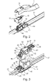
- Fig. 2
- shows the region of the wiper-blade fastening to the wiper arm with the use of a wiper-blade adapter in an exploded illustration,
- Fig. 3
- shows the wiper-blade-side adapter element and a supply element in an exploded illustration,
- Fig. 4
- shows a longitudinal section through a wiper blade according to the invention in the region of the wiper-blade fastening, and
- Fig. 5
- shows a section in the plane V-V of
Fig. 4 . - Identical elements or elements with an identical function are provided with the same reference numerals in the figures.
-
Fig. 1 shows awiper apparatus 100 for cleaning a vehicle window (not shown). Thewiper apparatus 100 has a wiper arm 1 which is fastened pivotably to a bearingelement 3 via a wiper-arm hinge 2. Thebearing element 3 is for its part connected to a shaft of a wiper drive (not shown). - A
wiper blade 10 according to the invention is fastened exchangeably to the wiper arm 1. A wiper-blade adapter 11 serves for this purpose which is arranged on thewiper blade 10 and comprises a wiper-arm-side adapter element 12 and a wiper-blade-side adapter element 13 which are arranged pivotably relative to one another in anaxis 14. As can be seen, in particular, usingFig. 2 , the wiper-arm-side adapter element 12 has alatching knob 16 which is formed integrally on the wiper-arm-side adapter element 12 via aspring tongue 17. In the mounted state of thewiper blade 10 on the wiper arm 1, thelatching knob 16 engages into alatching opening 18 which is formed on the upper side of the wiper arm 1, in such a way that thelatching knob 16 is arranged in a positively locking manner in the latching opening 18 and forms a latched connection. The release of thewiper blade 10 from the wiper arm 1 takes place in a known way by pressing thelatching knob 16 into the latching opening 18 with subsequent longitudinal displacement of thewiper blade 10 on the wiper arm 1 in the dismantling direction which is indicated by thearrow 19 inFig. 1 . - The
wiper blade 10 has a wiper-blade body 20 which has a strip-shaped wiper rubber 21 with awiper lip 22 which is connected to thewiper rubber 21 via a tilting web.Spring bars wiper rubber 21 on the two longitudinal sides of the wiper rubber 21 (Fig. 3 ). Thespring bars side adapter element 13 and are fixed on the latter. - In the exemplary embodiment, the
wiper blade 10 is configured as an electricallyheatable wiper blade 10. To this end for example, in each case one heating-foil element wiper lip 22, of the twospring bars 23, 24 (Fig. 5 ). Furthermore, thewiper blade 10 is configured as what is known as an "aquablade wiper 10", that is to say washing-fluid channels (not shown in the figures) are formed on both sides in the longitudinal direction of the wiper-blade body 20, which washing-fluid channels serve to supply spray nozzles (likewise not shown) with washing fluid. The supply of thewiper blade 10 with electricity for the heating device or washing fluid takes place by way of example via two washing-fluid hoses electrical connection line 30. Here, one washing-fluid hose 28 is assigned to one longitudinal side of the wiper-blade body 20, whereas the other washing-fluid hose 29 is assigned to the other longitudinal side of the wiper-blade body 20. As a result, it is made possible, depending on the movement direction of thewiper blade 10, to supply washing fluid to that side of thewiper blade 10 which leads in each case in the movement direction of thewiper blade 10. The washing-fluid hoses electrical connection line 30 are connected to asupply element 32 which is in two parts in the exemplary embodiment and is arranged in the wiper-blade adapter 11. - As can be seen, in particular, using
Figs 2 and 3 , the wiper-blade-side adapter element 13 hassupply stubs 33 for the washing fluid, which supplystubs 33 are arranged in the longitudinal direction of thewiper blade 10 and engage into longitudinal holes (not shown) of coveringelements blade adapter 11, and in which the abovementioned washing-fluid channels are formed. The upper sides of the coveringelements Fig. 2 , in order to increase the contact pressure of thewiper blade 10 on the vehicle window at relatively high speeds. The supply stubs 33 are connected hydraulically toinflow stubs side adapter element 13. Furthermore, two electrical connection pins 38, 39 can be seen inFig. 3 , via which electrical contact is made with the heating-foil elements - The wiper-blade-
side adapter element 13 has twoside walls axis 14, about which both the wiper-arm-side adapter element 12 and thesupply element 32 are mounted pivotably, is formed according to the invention by atransverse strut 44 which connects the twoside walls side adapter element 13 to one another. Acylindrical depression side wall transverse strut 44. The twodepressions cylindrical bearing projections opposite side walls side adapter element 12 which has a substantially U-shaped cross section (Fig. 5 ). - The
transverse strut 44 serves to mount and fasten thesupply element 32. Thesupply element 32 comprises afirst part element 51 and asecond part element 52 which serve for the hydraulic and electrical supply of thewiper blade 10 with washing fluid and electricity. Thefirst part element 51 which serves for the electrical power supply of the heating device has a block-shapedcentre region 53 with two connection plugs 54, 55 which make contact with theelectrical connection line 30. Thefirst part element 51 can be connected electrically to the connection pins 38, 39 vialines plug 58. - Hydraulic connection stubs 61, 62 of the
second part element 52 are arranged in a plane below thefirst part element 51, which hydraulic connection stubs 61, 62 can be connected to thesupply stubs 33 via a connection plug 63. - The
second part element 52 hasside walls centre region 53 of thefirst part element 51 is received. Furthermore, latching hooks 66, 67 are arranged on the twoside walls centre region 53 of thefirst part element 51. In addition, the twopart elements part elements - The two
side walls second part element 52form holding sections transverse strut 34. To this end, the holdingsections insertion region 70 which opens into areceptacle 71. Thereceptacle 71 which is configured as an aperture has a circular cross section, the diameter of thereceptacle 71 being adapted to the diameter of thetransverse strut 44 which likewise has a circular cross section. - In an aligned manner with respect to the
insertion regions 70 andreceptacles 71 of thesecond part element 52, thefirst part element 51 also has corresponding receptacles and insertion regions which cannot be seen in the figures, however. - The assembly of the
supply element 32 on the wiper-blade-side adapter element 13 takes place by moving thesupply element 32 and the wiper-blade-side adapter element 13 with respect to one another in the region of theinsertion regions 70 and thetransverse strut 44 in such a way that thereceptacles 71 form a latched connection with thetransverse strut 44, in which latched connection thereceptacles 71 enclose thetransverse strut 44 in a positively locking manner at least in regions. The wiper-arm-side adapter element 12 is subsequently connected to the wiper-blade-side adapter element 13, by theprojections depressions side walls side adapter element 13. - The above-described
wiper blade 10 can be changed or modified in a wide variety of ways, without deviating from the concept of the invention. In particular, instead of a two-piece supply element 32, it is conceivable to use a single-piece supply element 32, in which the twopart elements part elements wiper blade 10 is to have merely a washing function or a heating function. -
- 1
- Wiper arm
- 2
- Wiper-arm hinge
- 3
- Bearing element
- 10
- Wiper blade
- 11
- Wiper-blade adapter
- 12
- Wiper-arm-side adapter element
- 13
- Wiper-blade-side adapter element
- 14
- Axis
- 16
- Latching knob
- 17
- Spring tongue
- 18
- Latching opening
- 19
- Arrow
- 20
- Wiper-blade body
- 21
- Wiper rubber
- 22
- Wiper lip
- 23
- Spring bar
- 24
- Spring bar
- 25
- Heating-foil element
- 26
- Heating-foil element
- 28
- Washing-fluid hose
- 29
- Washing-fluid hose
- 30
- Connection line
- 32
- Supply element
- 33
- Supply stub
- 34
- Covering element
- 35
- Covering element
- 36
- Inflow stub
- 37
- Inflow stub
- 38
- Connection pin
- 39
- Connection pin
- 41
- Side wall
- 42
- Side wall
- 44
- Transverse strut
- 45
- Depression
- 46
- Depression
- 47
- Bearing projection
- 48
- Bearing projection
- 49
- Side wall
- 50
- Side wall
- 51
- First part element
- 52
- Second part element
- 53
- Centre region
- 54
- Connection plug
- 55
- Connection plug
- 56
- Line
- 57
- Line
- 58
- Latching plug
- 61
- Connection stub
- 62
- Connection stub
- 63
- Connection plug
- 64
- Side wall
- 65
- Side wall
- 66
- Latching hook
- 67
- Latching hook
- 68
- Holding arm
- 69
- Holding arm
- 70
- Insertion region
- 71
- Receptacle
- 100
- Wiper apparatus
Claims (8)
- A wiper blade (10) for cleaning vehicle windows, with a wiper-blade body (20) connected to a wiper-blade adapter (11), wherein the wiper-blade adapter (11) consists of a wiper-arm-side adapter element (12) and a wiper-blade-side adapter element (13) which are connected to one another and arranged pivotably relative to one another in an axis (14), and with a supply element (32) arranged pivotably in the axis (14) for the hydraulic and/or electrical supply of the wiper blade (10), wherein the supply element (32) is accommodated between two side walls (41, 42) of the wiper-blade-side adapter element (13),
characterised
in that the side walls (41, 42) are connected to one another with a transverse strut (44) arranged in the axis (14), in that the transverse strut (44) has a circular cross section at least in certain regions, and in that the supply element (32) has holding sections (68, 69) which encompass the transverse strut (44) in a positive-fitting manner at least in certain regions. - The wiper blade according to Claim 1,
characterised
in that the holding sections (68, 69) have insertion regions (70) which open into receptacles (71), and in that the holding sections (68, 69) can be pushed onto the transverse strut (44) by means of the insertion regions (70), wherein the holding sections (68, 69) form a snap connection with the transverse strut (44) in the mounted state of the supply element (32). - The wiper blade according to Claim 1 or 2,
characterised
in that the supply element (32) consists of a first part element (51) for electrical supply and a second part element (52) for hydraulic supply, and in that both part elements (51, 52) in each case have holding sections (68, 69) with openings which encompass the transverse strut (44). - The wiper blade according to Claim 3,
characterised
in that one part element (52) has side walls (64, 65), between which the other part element (51) is accommodated. - The wiper blade according to Claim 3 or 4,
characterised
in that the two part elements (51, 52) are connected to one another by means of an additional snap connection. - The wiper blade according to one of Claims 3 to 5,
characterised
in that the two part elements (51, 52) have mutually interacting geometries which align the receptacles (71) flush with one another. - The wiper blade according to Claim 1 or 2,
characterised
in that a single, integrally-constructed supply element (32) is provided, which is used both for hydraulic and electrical supply. - The wiper blade according to one of Claims 1 to 7,
characterised
in that the side walls (41, 42) of the wiper-blade-side adapter element (13) have depressions (46) for the pivotable mounting of the wiper-arm-side adapter element (12) on the external side facing away from the transverse strut (44).
Applications Claiming Priority (1)
| Application Number | Priority Date | Filing Date | Title |
|---|---|---|---|
| DE102012106944.1A DE102012106944A1 (en) | 2012-07-30 | 2012-07-30 | Wiper blade for cleaning vehicle windows |
Publications (3)
| Publication Number | Publication Date |
|---|---|
| EP2692595A2 true EP2692595A2 (en) | 2014-02-05 |
| EP2692595A3 EP2692595A3 (en) | 2017-12-20 |
| EP2692595B1 EP2692595B1 (en) | 2019-03-13 |
Family
ID=48874148
Family Applications (1)
| Application Number | Title | Priority Date | Filing Date |
|---|---|---|---|
| EP13177498.6A Active EP2692595B1 (en) | 2012-07-30 | 2013-07-22 | Wiper blade for cleaning vehicle windows |
Country Status (3)
| Country | Link |
|---|---|
| US (1) | US9452738B2 (en) |
| EP (1) | EP2692595B1 (en) |
| DE (1) | DE102012106944A1 (en) |
Cited By (1)
| Publication number | Priority date | Publication date | Assignee | Title |
|---|---|---|---|---|
| FR3017844A1 (en) * | 2014-02-24 | 2015-08-28 | Valeo Systemes Dessuyage | WIPER BLADE FOR VEHICLE WINDOWS |
Families Citing this family (28)
| Publication number | Priority date | Publication date | Assignee | Title |
|---|---|---|---|---|
| US9174609B2 (en) | 2011-04-21 | 2015-11-03 | Pylon Manufacturing Corp. | Wiper blade with cover |
| US9457768B2 (en) | 2011-04-21 | 2016-10-04 | Pylon Manufacturing Corp. | Vortex damping wiper blade |
| CA2843527C (en) | 2011-07-28 | 2018-11-27 | Pylon Manufacturing Corp. | Windshield wiper adapter, connector and assembly |
| US9108595B2 (en) | 2011-07-29 | 2015-08-18 | Pylon Manufacturing Corporation | Windshield wiper connector |
| US20130219649A1 (en) | 2012-02-24 | 2013-08-29 | Pylon Manufacturing Corp. | Wiper blade |
| US10723322B2 (en) | 2012-02-24 | 2020-07-28 | Pylon Manufacturing Corp. | Wiper blade with cover |
| MX385411B (en) | 2012-02-24 | 2025-03-18 | Pylon Mfg Corp | WINDSHIELD WIPER BLADES. |
| US10829092B2 (en) | 2012-09-24 | 2020-11-10 | Pylon Manufacturing Corp. | Wiper blade with modular mounting base |
| US10166951B2 (en) | 2013-03-15 | 2019-01-01 | Pylon Manufacturing Corp. | Windshield wiper connector |
| US9505380B2 (en) | 2014-03-07 | 2016-11-29 | Pylon Manufacturing Corp. | Windshield wiper connector and assembly |
| FR3023523B1 (en) * | 2014-07-11 | 2017-08-18 | Valeo Systemes Dessuyage | PIVOT CONNECTION FOR A VEHICLE WIPER BLADE |
| USD787308S1 (en) | 2014-10-03 | 2017-05-23 | Pylon Manufacturing Corp. | Wiper blade package |
| USD777079S1 (en) | 2014-10-03 | 2017-01-24 | Pylon Manufacturing Corp. | Wiper blade frame |
| JP6441156B2 (en) * | 2015-04-17 | 2018-12-19 | 株式会社ミツバ | Wiper device |
| JP6441155B2 (en) * | 2015-04-17 | 2018-12-19 | 株式会社ミツバ | Wiper device |
| WO2016167090A1 (en) * | 2015-04-17 | 2016-10-20 | 株式会社ミツバ | Wiper device |
| US10363905B2 (en) | 2015-10-26 | 2019-07-30 | Pylon Manufacturing Corp. | Wiper blade |
| DE102015226527A1 (en) * | 2015-12-22 | 2017-06-22 | Robert Bosch Gmbh | wiper device |
| AU2017268008A1 (en) | 2016-05-19 | 2018-11-22 | Pylon Manufacturing Corp. | Windshield wiper connector |
| US11040705B2 (en) | 2016-05-19 | 2021-06-22 | Pylon Manufacturing Corp. | Windshield wiper connector |
| CN109311452A (en) | 2016-05-19 | 2019-02-05 | 电缆塔制造有限公司 | windshield wiper connector |
| EP3458315B1 (en) | 2016-05-19 | 2021-09-08 | Pylon Manufacturing Corp. | Windshield wiper blade |
| CN109311450A (en) | 2016-05-19 | 2019-02-05 | 电缆塔制造有限公司 | windshield wiper connector |
| USD833954S1 (en) * | 2016-08-24 | 2018-11-20 | Kimblade Co., Ltd. | Windscreen wiper blade |
| DE102018251764A1 (en) * | 2018-12-28 | 2020-07-02 | Robert Bosch Gmbh | Wiper arm with connection adapter |
| DE102019203715A1 (en) * | 2019-03-19 | 2020-09-24 | Robert Bosch Gmbh | Windshield wiper arrangement with an adapter unit for establishing fluid-conducting and electrical connections |
| DE102019203720A1 (en) * | 2019-03-19 | 2020-09-24 | Robert Bosch Gmbh | Windshield wiper arrangement with a multi-part adapter device for establishing fluid-conducting connections |
| DE102020208468A1 (en) * | 2020-07-07 | 2022-01-13 | Robert Bosch Gesellschaft mit beschränkter Haftung | Wiper device for a windscreen wiper with a spray function |
Citations (1)
| Publication number | Priority date | Publication date | Assignee | Title |
|---|---|---|---|---|
| DE102010025687A1 (en) | 2010-06-30 | 2012-01-05 | Valeo Wischersysteme Gmbh | Wiper blade for cleaning vehicle windows |
Family Cites Families (8)
| Publication number | Priority date | Publication date | Assignee | Title |
|---|---|---|---|---|
| DE8614723U1 (en) * | 1986-05-31 | 1986-07-24 | Robert Bosch Gmbh, 70469 Stuttgart | Windshield wipers, in particular for the window panes of a motor vehicle |
| DE4439109B4 (en) * | 1994-11-02 | 2005-09-01 | Itt Automotive Europe Gmbh | With a wind deflector completeable wiper blade |
| FR2752798B1 (en) * | 1996-08-27 | 1998-10-09 | Valeo Systemes Dessuyage | WINDSCREEN WIPER COMPRISING A JOINT ADAPTER |
| FR2830823B1 (en) * | 2001-10-15 | 2004-02-27 | Valeo Systemes Dessuyage | MOTOR VEHICLE WIPER WITH SAFETY CLASP |
| FR2885105B1 (en) * | 2005-04-29 | 2007-06-29 | Valeo Systemes Dessuyage | ARRANGEMENT FOR THE MOUNTING WIPER BLADE ON A END OF TRAINING ARMS |
| DE102010005274B4 (en) * | 2010-01-20 | 2025-03-13 | Valeo Wischersysteme Gmbh | wiper blade |
| DE102010052314A1 (en) * | 2010-11-16 | 2012-05-16 | Daimler Ag | Wiper blade assembly and connection assembly with a wiper blade assembly and a wiper arm |
| FR2968259B1 (en) * | 2010-12-02 | 2016-04-29 | Valeo Systemes Dessuyage | ASSEMBLY COMPRISING A TERMINAL PIECE OF A WIPER ARM AND AN ELECTRICAL CONNECTOR |
-
2012
- 2012-07-30 DE DE102012106944.1A patent/DE102012106944A1/en not_active Withdrawn
-
2013
- 2013-07-22 EP EP13177498.6A patent/EP2692595B1/en active Active
- 2013-07-30 US US13/954,153 patent/US9452738B2/en active Active
Patent Citations (1)
| Publication number | Priority date | Publication date | Assignee | Title |
|---|---|---|---|---|
| DE102010025687A1 (en) | 2010-06-30 | 2012-01-05 | Valeo Wischersysteme Gmbh | Wiper blade for cleaning vehicle windows |
Cited By (1)
| Publication number | Priority date | Publication date | Assignee | Title |
|---|---|---|---|---|
| FR3017844A1 (en) * | 2014-02-24 | 2015-08-28 | Valeo Systemes Dessuyage | WIPER BLADE FOR VEHICLE WINDOWS |
Also Published As
| Publication number | Publication date |
|---|---|
| US20140026349A1 (en) | 2014-01-30 |
| DE102012106944A1 (en) | 2014-01-30 |
| EP2692595B1 (en) | 2019-03-13 |
| US9452738B2 (en) | 2016-09-27 |
| EP2692595A3 (en) | 2017-12-20 |
Similar Documents
| Publication | Publication Date | Title |
|---|---|---|
| EP2692595B1 (en) | Wiper blade for cleaning vehicle windows | |
| EP2692597B1 (en) | Wiper blade for cleaning vehicle windows | |
| KR101600122B1 (en) | Wiper arm/wiper blade connection and wiper blade | |
| JP5603330B2 (en) | Wiper blade, wiper arm and wiper device | |
| EP2658757B1 (en) | Wiper blade for the cleaning of windows of motor vehicles | |
| EP2588353B1 (en) | Wiper blade for cleaning vehicle windscreens | |
| EP1681216B1 (en) | Windshield wiper device | |
| CN102656065B (en) | Wiper blades with flat beam construction | |
| EP1876074B1 (en) | Windshield wiper device | |
| CN103648858A (en) | Connection mount, mechanical connector and wiping device for a motor vehicle | |
| EP1745997B1 (en) | Windscreen wiper device | |
| CN103958298A (en) | Wiper blades for cleaning vehicle windows | |
| CN107054301B (en) | Adapter for a windscreen wiper device for a motor vehicle | |
| CN103415420B (en) | Be particularly useful for the Wiper blade adapter device of window glass of motor vehicle wiper device | |
| EP4010229B1 (en) | A windscreen wiper device of the flat blade type | |
| CN103826937B (en) | Bracing or strutting arrangement and assembly and the method for installing a pair Wiper blade | |
| WO2021043499A1 (en) | Cover profile for a wiper arm of a wiping system and method for mounting a wiper arm | |
| CN107031574B (en) | Wiper blade device | |
| CN103228500A (en) | Wiper blade device | |
| CN103648859A (en) | Wiper blade with an adaptor unit for coupling to a wiper arm | |
| CN105459962B (en) | wiper | |
| EP2692596B1 (en) | Wiper blade for cleaning vehicle windows | |
| EP3386810B1 (en) | Windscreen wiper device | |
| CN221393394U (en) | End limiting structure of wiper strip of wiper and wiper | |
| CN101932482A (en) | Connection platform for a motor vehicle windscreen wiper blade |
Legal Events
| Date | Code | Title | Description |
|---|---|---|---|
| 17P | Request for examination filed |
Effective date: 20130722 |
|
| AK | Designated contracting states |
Kind code of ref document: A2 Designated state(s): AL AT BE BG CH CY CZ DE DK EE ES FI FR GB GR HR HU IE IS IT LI LT LU LV MC MK MT NL NO PL PT RO RS SE SI SK SM TR |
|
| AX | Request for extension of the european patent |
Extension state: BA ME |
|
| PUAI | Public reference made under article 153(3) epc to a published international application that has entered the european phase |
Free format text: ORIGINAL CODE: 0009012 |
|
| PUAL | Search report despatched |
Free format text: ORIGINAL CODE: 0009013 |
|
| AK | Designated contracting states |
Kind code of ref document: A3 Designated state(s): AL AT BE BG CH CY CZ DE DK EE ES FI FR GB GR HR HU IE IS IT LI LT LU LV MC MK MT NL NO PL PT RO RS SE SI SK SM TR |
|
| AX | Request for extension of the european patent |
Extension state: BA ME |
|
| RIC1 | Information provided on ipc code assigned before grant |
Ipc: B60S 1/52 20060101ALI20171113BHEP Ipc: B60S 1/40 20060101ALI20171113BHEP Ipc: B60S 1/38 20060101AFI20171113BHEP |
|
| GRAP | Despatch of communication of intention to grant a patent |
Free format text: ORIGINAL CODE: EPIDOSNIGR1 |
|
| STAA | Information on the status of an ep patent application or granted ep patent |
Free format text: STATUS: GRANT OF PATENT IS INTENDED |
|
| INTG | Intention to grant announced |
Effective date: 20181011 |
|
| GRAS | Grant fee paid |
Free format text: ORIGINAL CODE: EPIDOSNIGR3 |
|
| GRAA | (expected) grant |
Free format text: ORIGINAL CODE: 0009210 |
|
| STAA | Information on the status of an ep patent application or granted ep patent |
Free format text: STATUS: THE PATENT HAS BEEN GRANTED |
|
| AK | Designated contracting states |
Kind code of ref document: B1 Designated state(s): AL AT BE BG CH CY CZ DE DK EE ES FI FR GB GR HR HU IE IS IT LI LT LU LV MC MK MT NL NO PL PT RO RS SE SI SK SM TR |
|
| REG | Reference to a national code |
Ref country code: GB Ref legal event code: FG4D |
|
| REG | Reference to a national code |
Ref country code: CH Ref legal event code: EP Ref country code: AT Ref legal event code: REF Ref document number: 1107287 Country of ref document: AT Kind code of ref document: T Effective date: 20190315 |
|
| REG | Reference to a national code |
Ref country code: IE Ref legal event code: FG4D |
|
| REG | Reference to a national code |
Ref country code: DE Ref legal event code: R096 Ref document number: 602013052166 Country of ref document: DE |
|
| REG | Reference to a national code |
Ref country code: NL Ref legal event code: MP Effective date: 20190313 |
|
| REG | Reference to a national code |
Ref country code: LT Ref legal event code: MG4D |
|
| PG25 | Lapsed in a contracting state [announced via postgrant information from national office to epo] |
Ref country code: FI Free format text: LAPSE BECAUSE OF FAILURE TO SUBMIT A TRANSLATION OF THE DESCRIPTION OR TO PAY THE FEE WITHIN THE PRESCRIBED TIME-LIMIT Effective date: 20190313 Ref country code: SE Free format text: LAPSE BECAUSE OF FAILURE TO SUBMIT A TRANSLATION OF THE DESCRIPTION OR TO PAY THE FEE WITHIN THE PRESCRIBED TIME-LIMIT Effective date: 20190313 Ref country code: LT Free format text: LAPSE BECAUSE OF FAILURE TO SUBMIT A TRANSLATION OF THE DESCRIPTION OR TO PAY THE FEE WITHIN THE PRESCRIBED TIME-LIMIT Effective date: 20190313 Ref country code: NO Free format text: LAPSE BECAUSE OF FAILURE TO SUBMIT A TRANSLATION OF THE DESCRIPTION OR TO PAY THE FEE WITHIN THE PRESCRIBED TIME-LIMIT Effective date: 20190613 |
|
| PG25 | Lapsed in a contracting state [announced via postgrant information from national office to epo] |
Ref country code: RS Free format text: LAPSE BECAUSE OF FAILURE TO SUBMIT A TRANSLATION OF THE DESCRIPTION OR TO PAY THE FEE WITHIN THE PRESCRIBED TIME-LIMIT Effective date: 20190313 Ref country code: LV Free format text: LAPSE BECAUSE OF FAILURE TO SUBMIT A TRANSLATION OF THE DESCRIPTION OR TO PAY THE FEE WITHIN THE PRESCRIBED TIME-LIMIT Effective date: 20190313 Ref country code: NL Free format text: LAPSE BECAUSE OF FAILURE TO SUBMIT A TRANSLATION OF THE DESCRIPTION OR TO PAY THE FEE WITHIN THE PRESCRIBED TIME-LIMIT Effective date: 20190313 Ref country code: GR Free format text: LAPSE BECAUSE OF FAILURE TO SUBMIT A TRANSLATION OF THE DESCRIPTION OR TO PAY THE FEE WITHIN THE PRESCRIBED TIME-LIMIT Effective date: 20190614 Ref country code: HR Free format text: LAPSE BECAUSE OF FAILURE TO SUBMIT A TRANSLATION OF THE DESCRIPTION OR TO PAY THE FEE WITHIN THE PRESCRIBED TIME-LIMIT Effective date: 20190313 Ref country code: BG Free format text: LAPSE BECAUSE OF FAILURE TO SUBMIT A TRANSLATION OF THE DESCRIPTION OR TO PAY THE FEE WITHIN THE PRESCRIBED TIME-LIMIT Effective date: 20190613 |
|
| REG | Reference to a national code |
Ref country code: AT Ref legal event code: MK05 Ref document number: 1107287 Country of ref document: AT Kind code of ref document: T Effective date: 20190313 |
|
| PG25 | Lapsed in a contracting state [announced via postgrant information from national office to epo] |
Ref country code: EE Free format text: LAPSE BECAUSE OF FAILURE TO SUBMIT A TRANSLATION OF THE DESCRIPTION OR TO PAY THE FEE WITHIN THE PRESCRIBED TIME-LIMIT Effective date: 20190313 Ref country code: ES Free format text: LAPSE BECAUSE OF FAILURE TO SUBMIT A TRANSLATION OF THE DESCRIPTION OR TO PAY THE FEE WITHIN THE PRESCRIBED TIME-LIMIT Effective date: 20190313 Ref country code: RO Free format text: LAPSE BECAUSE OF FAILURE TO SUBMIT A TRANSLATION OF THE DESCRIPTION OR TO PAY THE FEE WITHIN THE PRESCRIBED TIME-LIMIT Effective date: 20190313 Ref country code: CZ Free format text: LAPSE BECAUSE OF FAILURE TO SUBMIT A TRANSLATION OF THE DESCRIPTION OR TO PAY THE FEE WITHIN THE PRESCRIBED TIME-LIMIT Effective date: 20190313 Ref country code: IT Free format text: LAPSE BECAUSE OF FAILURE TO SUBMIT A TRANSLATION OF THE DESCRIPTION OR TO PAY THE FEE WITHIN THE PRESCRIBED TIME-LIMIT Effective date: 20190313 Ref country code: SK Free format text: LAPSE BECAUSE OF FAILURE TO SUBMIT A TRANSLATION OF THE DESCRIPTION OR TO PAY THE FEE WITHIN THE PRESCRIBED TIME-LIMIT Effective date: 20190313 Ref country code: PT Free format text: LAPSE BECAUSE OF FAILURE TO SUBMIT A TRANSLATION OF THE DESCRIPTION OR TO PAY THE FEE WITHIN THE PRESCRIBED TIME-LIMIT Effective date: 20190713 Ref country code: AL Free format text: LAPSE BECAUSE OF FAILURE TO SUBMIT A TRANSLATION OF THE DESCRIPTION OR TO PAY THE FEE WITHIN THE PRESCRIBED TIME-LIMIT Effective date: 20190313 |
|
| PG25 | Lapsed in a contracting state [announced via postgrant information from national office to epo] |
Ref country code: PL Free format text: LAPSE BECAUSE OF FAILURE TO SUBMIT A TRANSLATION OF THE DESCRIPTION OR TO PAY THE FEE WITHIN THE PRESCRIBED TIME-LIMIT Effective date: 20190313 Ref country code: SM Free format text: LAPSE BECAUSE OF FAILURE TO SUBMIT A TRANSLATION OF THE DESCRIPTION OR TO PAY THE FEE WITHIN THE PRESCRIBED TIME-LIMIT Effective date: 20190313 |
|
| REG | Reference to a national code |
Ref country code: DE Ref legal event code: R097 Ref document number: 602013052166 Country of ref document: DE |
|
| PG25 | Lapsed in a contracting state [announced via postgrant information from national office to epo] |
Ref country code: AT Free format text: LAPSE BECAUSE OF FAILURE TO SUBMIT A TRANSLATION OF THE DESCRIPTION OR TO PAY THE FEE WITHIN THE PRESCRIBED TIME-LIMIT Effective date: 20190313 Ref country code: IS Free format text: LAPSE BECAUSE OF FAILURE TO SUBMIT A TRANSLATION OF THE DESCRIPTION OR TO PAY THE FEE WITHIN THE PRESCRIBED TIME-LIMIT Effective date: 20190713 |
|
| PLBE | No opposition filed within time limit |
Free format text: ORIGINAL CODE: 0009261 |
|
| STAA | Information on the status of an ep patent application or granted ep patent |
Free format text: STATUS: NO OPPOSITION FILED WITHIN TIME LIMIT |
|
| PG25 | Lapsed in a contracting state [announced via postgrant information from national office to epo] |
Ref country code: DK Free format text: LAPSE BECAUSE OF FAILURE TO SUBMIT A TRANSLATION OF THE DESCRIPTION OR TO PAY THE FEE WITHIN THE PRESCRIBED TIME-LIMIT Effective date: 20190313 |
|
| 26N | No opposition filed |
Effective date: 20191216 |
|
| PG25 | Lapsed in a contracting state [announced via postgrant information from national office to epo] |
Ref country code: SI Free format text: LAPSE BECAUSE OF FAILURE TO SUBMIT A TRANSLATION OF THE DESCRIPTION OR TO PAY THE FEE WITHIN THE PRESCRIBED TIME-LIMIT Effective date: 20190313 Ref country code: MC Free format text: LAPSE BECAUSE OF FAILURE TO SUBMIT A TRANSLATION OF THE DESCRIPTION OR TO PAY THE FEE WITHIN THE PRESCRIBED TIME-LIMIT Effective date: 20190313 |
|
| REG | Reference to a national code |
Ref country code: CH Ref legal event code: PL |
|
| GBPC | Gb: european patent ceased through non-payment of renewal fee |
Effective date: 20190722 |
|
| PG25 | Lapsed in a contracting state [announced via postgrant information from national office to epo] |
Ref country code: TR Free format text: LAPSE BECAUSE OF FAILURE TO SUBMIT A TRANSLATION OF THE DESCRIPTION OR TO PAY THE FEE WITHIN THE PRESCRIBED TIME-LIMIT Effective date: 20190313 |
|
| REG | Reference to a national code |
Ref country code: BE Ref legal event code: MM Effective date: 20190731 |
|
| PG25 | Lapsed in a contracting state [announced via postgrant information from national office to epo] |
Ref country code: GB Free format text: LAPSE BECAUSE OF NON-PAYMENT OF DUE FEES Effective date: 20190722 |
|
| PG25 | Lapsed in a contracting state [announced via postgrant information from national office to epo] |
Ref country code: LI Free format text: LAPSE BECAUSE OF NON-PAYMENT OF DUE FEES Effective date: 20190731 Ref country code: CH Free format text: LAPSE BECAUSE OF NON-PAYMENT OF DUE FEES Effective date: 20190731 Ref country code: BE Free format text: LAPSE BECAUSE OF NON-PAYMENT OF DUE FEES Effective date: 20190731 Ref country code: LU Free format text: LAPSE BECAUSE OF NON-PAYMENT OF DUE FEES Effective date: 20190722 |
|
| PG25 | Lapsed in a contracting state [announced via postgrant information from national office to epo] |
Ref country code: IE Free format text: LAPSE BECAUSE OF NON-PAYMENT OF DUE FEES Effective date: 20190722 |
|
| PG25 | Lapsed in a contracting state [announced via postgrant information from national office to epo] |
Ref country code: CY Free format text: LAPSE BECAUSE OF FAILURE TO SUBMIT A TRANSLATION OF THE DESCRIPTION OR TO PAY THE FEE WITHIN THE PRESCRIBED TIME-LIMIT Effective date: 20190313 |
|
| PG25 | Lapsed in a contracting state [announced via postgrant information from national office to epo] |
Ref country code: HU Free format text: LAPSE BECAUSE OF FAILURE TO SUBMIT A TRANSLATION OF THE DESCRIPTION OR TO PAY THE FEE WITHIN THE PRESCRIBED TIME-LIMIT; INVALID AB INITIO Effective date: 20130722 Ref country code: MT Free format text: LAPSE BECAUSE OF FAILURE TO SUBMIT A TRANSLATION OF THE DESCRIPTION OR TO PAY THE FEE WITHIN THE PRESCRIBED TIME-LIMIT Effective date: 20190313 |
|
| PG25 | Lapsed in a contracting state [announced via postgrant information from national office to epo] |
Ref country code: MK Free format text: LAPSE BECAUSE OF FAILURE TO SUBMIT A TRANSLATION OF THE DESCRIPTION OR TO PAY THE FEE WITHIN THE PRESCRIBED TIME-LIMIT Effective date: 20190313 |
|
| P01 | Opt-out of the competence of the unified patent court (upc) registered |
Effective date: 20230528 |
|
| PGFP | Annual fee paid to national office [announced via postgrant information from national office to epo] |
Ref country code: DE Payment date: 20250711 Year of fee payment: 13 |
|
| PGFP | Annual fee paid to national office [announced via postgrant information from national office to epo] |
Ref country code: FR Payment date: 20250730 Year of fee payment: 13 |