EP2692384A2 - Gas administration device, especially resuscitation device - Google Patents
Gas administration device, especially resuscitation device Download PDFInfo
- Publication number
- EP2692384A2 EP2692384A2 EP13000649.7A EP13000649A EP2692384A2 EP 2692384 A2 EP2692384 A2 EP 2692384A2 EP 13000649 A EP13000649 A EP 13000649A EP 2692384 A2 EP2692384 A2 EP 2692384A2
- Authority
- EP
- European Patent Office
- Prior art keywords
- lever
- cam
- compressible chamber
- gas
- administration device
- Prior art date
- Legal status (The legal status is an assumption and is not a legal conclusion. Google has not performed a legal analysis and makes no representation as to the accuracy of the status listed.)
- Withdrawn
Links
- 239000007789 gas Substances 0.000 claims abstract description 37
- 230000007246 mechanism Effects 0.000 claims abstract description 35
- QVGXLLKOCUKJST-UHFFFAOYSA-N atomic oxygen Chemical compound [O] QVGXLLKOCUKJST-UHFFFAOYSA-N 0.000 claims abstract description 18
- 239000001301 oxygen Substances 0.000 claims abstract description 18
- 229910052760 oxygen Inorganic materials 0.000 claims abstract description 18
- 230000003139 buffering effect Effects 0.000 claims description 6
- 239000012528 membrane Substances 0.000 description 14
- 230000035565 breathing frequency Effects 0.000 description 5
- 230000029058 respiratory gaseous exchange Effects 0.000 description 5
- 230000003028 elevating effect Effects 0.000 description 3
- 230000001419 dependent effect Effects 0.000 description 2
- 230000000694 effects Effects 0.000 description 2
- 230000003993 interaction Effects 0.000 description 2
- 210000004072 lung Anatomy 0.000 description 2
- 230000004048 modification Effects 0.000 description 2
- 238000012986 modification Methods 0.000 description 2
- 230000009467 reduction Effects 0.000 description 2
- 238000002560 therapeutic procedure Methods 0.000 description 2
- 230000009471 action Effects 0.000 description 1
- 238000007599 discharging Methods 0.000 description 1
- 238000006073 displacement reaction Methods 0.000 description 1
- 239000013536 elastomeric material Substances 0.000 description 1
- 230000005611 electricity Effects 0.000 description 1
- 230000003287 optical effect Effects 0.000 description 1
- 229920001296 polysiloxane Polymers 0.000 description 1
- 239000002516 radical scavenger Substances 0.000 description 1
- 238000011144 upstream manufacturing Methods 0.000 description 1
- 238000004804 winding Methods 0.000 description 1
Images


Classifications
-
- A—HUMAN NECESSITIES
- A61—MEDICAL OR VETERINARY SCIENCE; HYGIENE
- A61M—DEVICES FOR INTRODUCING MEDIA INTO, OR ONTO, THE BODY; DEVICES FOR TRANSDUCING BODY MEDIA OR FOR TAKING MEDIA FROM THE BODY; DEVICES FOR PRODUCING OR ENDING SLEEP OR STUPOR
- A61M16/00—Devices for influencing the respiratory system of patients by gas treatment, e.g. ventilators; Tracheal tubes
- A61M16/0057—Pumps therefor
- A61M16/0075—Bellows-type
-
- A—HUMAN NECESSITIES
- A61—MEDICAL OR VETERINARY SCIENCE; HYGIENE
- A61M—DEVICES FOR INTRODUCING MEDIA INTO, OR ONTO, THE BODY; DEVICES FOR TRANSDUCING BODY MEDIA OR FOR TAKING MEDIA FROM THE BODY; DEVICES FOR PRODUCING OR ENDING SLEEP OR STUPOR
- A61M16/00—Devices for influencing the respiratory system of patients by gas treatment, e.g. ventilators; Tracheal tubes
- A61M16/10—Preparation of respiratory gases or vapours
- A61M16/12—Preparation of respiratory gases or vapours by mixing different gases
-
- A—HUMAN NECESSITIES
- A61—MEDICAL OR VETERINARY SCIENCE; HYGIENE
- A61M—DEVICES FOR INTRODUCING MEDIA INTO, OR ONTO, THE BODY; DEVICES FOR TRANSDUCING BODY MEDIA OR FOR TAKING MEDIA FROM THE BODY; DEVICES FOR PRODUCING OR ENDING SLEEP OR STUPOR
- A61M16/00—Devices for influencing the respiratory system of patients by gas treatment, e.g. ventilators; Tracheal tubes
- A61M16/20—Valves specially adapted to medical respiratory devices
- A61M16/208—Non-controlled one-way valves, e.g. exhalation, check, pop-off non-rebreathing valves
-
- A—HUMAN NECESSITIES
- A61—MEDICAL OR VETERINARY SCIENCE; HYGIENE
- A61M—DEVICES FOR INTRODUCING MEDIA INTO, OR ONTO, THE BODY; DEVICES FOR TRANSDUCING BODY MEDIA OR FOR TAKING MEDIA FROM THE BODY; DEVICES FOR PRODUCING OR ENDING SLEEP OR STUPOR
- A61M2202/00—Special media to be introduced, removed or treated
- A61M2202/02—Gases
- A61M2202/0208—Oxygen
-
- A—HUMAN NECESSITIES
- A61—MEDICAL OR VETERINARY SCIENCE; HYGIENE
- A61M—DEVICES FOR INTRODUCING MEDIA INTO, OR ONTO, THE BODY; DEVICES FOR TRANSDUCING BODY MEDIA OR FOR TAKING MEDIA FROM THE BODY; DEVICES FOR PRODUCING OR ENDING SLEEP OR STUPOR
- A61M2205/00—General characteristics of the apparatus
- A61M2205/33—Controlling, regulating or measuring
- A61M2205/3331—Pressure; Flow
- A61M2205/3341—Pressure; Flow stabilising pressure or flow to avoid excessive variation
-
- A—HUMAN NECESSITIES
- A61—MEDICAL OR VETERINARY SCIENCE; HYGIENE
- A61M—DEVICES FOR INTRODUCING MEDIA INTO, OR ONTO, THE BODY; DEVICES FOR TRANSDUCING BODY MEDIA OR FOR TAKING MEDIA FROM THE BODY; DEVICES FOR PRODUCING OR ENDING SLEEP OR STUPOR
- A61M2205/00—General characteristics of the apparatus
- A61M2205/50—General characteristics of the apparatus with microprocessors or computers
- A61M2205/502—User interfaces, e.g. screens or keyboards
Definitions
- the present invention concerns a gas administration device, especially a resuscitation device, according to the preamble of claim 1.
- Gas administrators serve to supply air or oxygen to a patient.
- Typical examples are bag valve mask - type resuscitators.
- pump-like resuscitators and pressure-limited resuscitators are known.
- WO 2008/147229 A1 describes an electrically operable resuscitation device comprising a pump including a rigid cylinder including at least one gas inlet and at least one gas outlet, a piston to travel in said cylinder, and at least one valve, the or each valve configured to allow gas to be displaced into said cylinder through at least one gas inlet during at least one of a first stroke direction and second stroke direction of said piston in said cylinder, and for allowing gas displaced through said at least one gas outlet during an opposite of said at least one of the first stroke direction and second stroke direction of said piston in said cylinder.
- This mechanism is considered complicated, and not easily adjustable to specific needs.
- the object of the invention is thus to provide a resuscitation device, which is easy to operate and modify according to different conditions and requirements.
- a gas administration device especially a resuscitation device, with which the tidal volume, breathing frequency and maximum pressure delivered to a patient can easily be modified, thus avoiding excessive volumes of gas being delivered to a patient.
- the resuscitation device according to the invention allows a simple modelling of a clinically desired or validated inhalation profile by means of providing a corresponding cam profile.
- the position of the compressible chamber with respect to the at least one lever is adjustable by means of a positioning mechanism, especially an elevating screw mechanism.
- a positioning mechanism especially an elevating screw mechanism.
- Such a mechanism allows a simple and reliable positioning of the compressible chamber relative to the lever mechanism, whereby the tidal volume can be easily adjusted by using pusher devices for adjusting the position of the compressible chamber.
- the lever mechanism and/or the bellows comprises a retaining mechanism, especially a return spring mechanism.
- a retaining mechanism especially a return spring mechanism.
- Preferred embodiments of such retaining means comprise at least one spring acting on the lever and/or the compressible chamber, or an elastic component. It is especially possible to inherently provide the compressible chamber with such spring or elastic characteristics.
- the bellows can be provided as a "self inflating bag", i.e. essentially a bag with sufficient compliance. In case of insufficient compliance, this can be enhanced by providing additional spring means along the bellows axis or, for example, by means of a torsion spring in the axis of rotation of the lever. These means can act on the upper side of the bellows and ensure that bellows, lever and cam contact each other at any time, i.e. that the opening or momentary volume of the bellows is always defined by the position of the cam.
- the cam is provided with a cam profile, by means of which a clinically validated or desired inhalation profile can be generated.
- a cam profile can be provided in an interchangeable manner.
- a cam can be provided to be manually exchangeable.
- a bearing mechanism can be provided on the at least one lever of the lever mechanism, on which the cam acts. This can minimize any frictional effects, thus leading to a longer lifetime and less wear and tear, as well as increased reliability of the resuscitation device.
- a PEEP-mechanism at an outlet side of the compressible chamber.
- Such a PEEP device can especially be provided with a novel membrane interacting with an adjustable spring, as described in detail with reference to the figures.
- a dosage means for additional dosage of oxygen into the gas, especially air, delivered by the compressible chamber can especially comprise a flow regulator for providing constant flow of additional oxygen, especially in order to keep a FIO 2 (fraction of inspired oxygen) value constant.
- a dosage means is provided between the compressible chamber and the PEEP-mechanism.
- a means for buffering a gas volume administed to a patient provided at the outlet side of the compressible chamber, especially between the compressible chamber and the PEEP-mechanism.
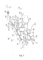
- Fig. 1 shows a preferred embodiment of a resuscitator according to the present invention, generally denoted 100.
- the resuscitator 100 comprises a compressible chamber in form of a bellows 110.
- the bellows 110 comprises an inlet 111 for admission of gas, i.e. air or oxygen-containing gas, into the bellows 110. It further comprises an outlet 112 for directing gas to a patient P.
- Inlet 111 and outlet 112 are provided with corresponding check valves, as is well known in the prior art (not shown).
- the bellows 110 is compressible by means of a lever mechanism 120 comprising a first lever 122 and a return spring 124 acting as retaining mechanism.
- the lever 122 is pivotable about a pivot axis 125, in the vicinity of which the return spring 124 can be positioned, for example in case of usage of a torsion spring as return spring 124.
- the lever 122 can rotate in a clockwise and anti-clockwise direction, as indicated by double pointed arrow 126.
- This pivoting movement of the lever 122 is generated by rotation of a cam 130, which rotates about a cam axis 132. It is especially preferred that the cam rotates about cam axis 132 in a steady manner, i.e. with constant angular velocity.
- the profile of the cam is designed so that a desired clinically valid inhalation profile can be achieved.
- the profile of the cam 130 determines the I/E-ratio (time ratio of inhalation to exhalation), for example 1:1.5.
- the cam 130 is driveable by a drive (not shown), that is controlled to accomplish certain RPMs.
- a computing device 159 is provided to allow the user to select the parameters and display the data via a graphical user interface 160.
- inhalation/exhalation valves manifolds, tubings or masks used can be provided in such a way.
- the lever 122 is pivotable about axis 125 and thus positionable at an angle relative to an (imaginary) horizontal axis 140.
- the bellows 110 is moveable/displaceable along or parallel to this axis 140.
- the lever 122 is shown at a maximum angle ⁇ max relative to the horizontal axis 140.
- This angle ⁇ max corresponds to a minimum radius 133 of the cam 130 contacting the lever 122.
- the maximum radius of the cam 134 corresponds to a minimum angle ⁇ min of the lever (not shown).
- the angle ⁇ min corresponds to the axis140. i.e. the lever 122 is pivotable between the position shown in figure 1 and axis 140.
- the lever 122 moves backwards and forwards (clockwise and anti-clockwise) between ⁇ max and ⁇ min (preferable 0°, corresponding to axis 140), corresponding to the angular position of cam 130.
- the bellows 110 is, as mentioned, displaceable along horizontal axis 140. Such a displacement can be achieved by a corresponding drive 150, which drives a (positioning mechanism) 152, preferably an elevating screw mechanism comprising a thread rod 152a. Expediently, this thread rod interacts withy threading forming a guide (denoted as 154 in Fig. 1 ).
- the side of the bellows interacting with the lever 122 can be provided with an interaction mechanism 117, for example a holder 117a supporting a bearing 117b, the bearing contacting the lower side of the lever 122.
- a bearing mechanism 138 or other friction reduction means can be provided on the area of the lever 122 with which the cam interacts.
- drive means can also be provided in form of, for example, a simple linear actuator or a pusher mechanism.
- the bellows will be compressed from an intermediate maximum volume, as for example compared to a position further to the right, i.e. nearer to drive 150, where the maximum volume of the bellows will be larger.
- a position of the bellows further to the left, i.e. nearer to pivot axis 125 will lead to a smaller maximum volume.
- the bellows 110 is moved, the smaller the tidal volume, which the bellows 110 administers (i.e. the difference between maximum and minimum volume) becomes.
- the acutation of the lever 122 can be performed by a driven cam, as described, or, additionally or alternatively, by manually driving the cam, or even by directly actuating the lever, i.e. without making use of the cam.
- the bellows 110 is driven by lever 122 being rotatable about pivot axis 125.
- lever 122 it is also possible to drive the bellows by means of a lever performing a translational movement along axis 140.
- the cam 130 is arranged to the left of the lower end 138 of lever 122. Through actuation by cam 130, this end 138 of lever 122 performs a translational movement along a first guide 190 parallel to axis 140.
- the upper end of lever 122 is designated 139. It is correspondingly moveable (translatable) in a guide 191, which extends parallel to guide 190 and thus parallel to axis 140.
- lever 122 will perform a translational movement backwards and forwards along axis 140, which will lead to a corresponding deflation and inflation of bellows 110.
- a spring 124 serves to expand the bellows 110 while lever 122 is moving away from bellows 110, i.e. to the left in Figure 4 .
- the angle ⁇ in Fig. 4 which defines the inclination of lever 122 with respect to axis 140, is adjustable by means of a shifting mechanism for guide 191, by means of which guide 191 can be moved towards or away from axis 140, as symbolized by double pointed arrow Q.
- the shifting mechanism can comprise a wheel 150 and a pusher 152 acting on guide 191.
- FIG. 5 A similar mechanism employing parallel levers is schematically shown in Figure 5 , where again similar or identical components are designated with the same reference numerals.
- Three interconnected parallel levers 122a, 122b, 122c are provided, which can be jointly moved along axis 140 by means of cam 130. Inclination angled ⁇ can be set by means of an adjustment mechanism comprising a wheel 150.
- the tidal volume of the bellows can be manipulated in a desired way.
- tidal volumes typical breathing patterns, breathing frequencies, ratio of I/E, minute volumes and pressure limitations can be set, modified and controlled. Furthermore, corresponding information can be presented to a patient or a user in an easily understandable way (graphic display). Critical situations, for example elevated pressure, can, for example, be indicated by means of an acoustical or an optical alarm.
- Other breathing parameters for example minute volumes that result from the set parameters can be calculated and displayed to a user: The resulting breathing pattern that will be administered to the patient can be graphically displayed.
- a fully automatic mode e.g. comprising predetermination of tidal volume and breathing frequency
- half automatic modes can be advantageous, in which, for example, individual breaths of air can be delivered/simulated by for example pressing a control device (button).
- the user interface they always display the current breathing parameters that result from a manual operation, e.g. by counting the control device knob actuations or the rotations of the cams.
- manual modes of operation are possible, for example in case of lacking knowledge of the device by a user. Taking into account that this device is intended as life saving device, certain events like lacking electricity (lacking mains or battery) or device failures can be mitigated by a manual backup option and the therapy can be continued without harming the patient.
- the device according to the invention ensures predetermined maximum tidal volumes and maximum pressures in all modes of operation.
- a manual operation can be detected for example when a contact between the cam 130 and the leaver 122 is lost, and a second contact in the 0°-position shows that the user is effecting a manual resuscitation. In this case also, breathing parameters could be calculated by the device.
- the device according to the invention can be advantageously provided together with a "PEEP”-mechanism (PEEP: positive end expiratory pressure).
- PEEP positive end expiratory pressure
- PEEP Positive End-Expiratory Pressure designates a positive pressure within the lungs, which can be generated during resuscitation. Various medical conditions can be alleviated by providing such a positive pressure. It is advantageous to be able to modify a PEEP generated or provided by a resuscitation device, in order to accommodate various medical conditions.
- Figure 1 also shows how the inhalation/exhalation valve assembly shown comprises a PEEP valve without adding further components to the disposable circuitry.
- a valve manifold 200 comprising various functional sections is provided in a case 300 (schematically shown), both assembled to one physical, disposable component. This assembly is positioned between the outlet side 112 of the bellows 110 and the patient P.
- Valve manifold 200 comprises an opening 202 within a first section 201, which, during reduction of the bellows volume, i.e. during inhalation, will allow air to pass from outlet 112 to patient P.
- air can be discharged by means of a second section 208 of the valve manifold 200, which is urged against an opening 310 of the disposable case 300 by means of a force actuator, preferably a spring 170.
- This second section 208 is delimited by a lip 210.
- the force acting against this second section 208 i.e. generated by spring 170
- the force is relevant for the pressure that needs to be applied on the second section 208, representing the PEEP.
- This passage of air is symbolized by curved arrow P2.
- the lip 210 surrounds said opening 310.
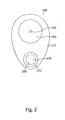
- Fig. 2 shows the membrane 200 as used in the embodiment of Fig 1 .
- the membrane may be preferably produced as a single part comprising of an elastomeric material like silicone. While prior art incorporates only components 201 and 202, this embodiment according to the invention additionally also comprises components 206, 208, 210.
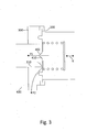
- FIG. 3 A further embodiment of a PEEP-valve 400 and its positioning in a disposable case is shown in Fig. 3 .
- the lip designated 410
- the PEEP-valve 400 covers an opening 310 of the disposable case 300.
- inspiration can be effected through valve opening 402 (arrow P1).
- Expiration is effected through opening 410 (arrow P2).
- PEEP is adjustable by means of spring 420 (symbolised by double pointed arrow R).
- a further advantageous embodiment of the invention comprises the additional dosage of oxygen to inlet air, i.e. referring to Fig. 1 to air entering the system via inlet 111.
- Such an additional dosage of oxygen can be affected on the inlet side of the compressible chamber, i.e. in connection with passage 111, as will be explained in the following:
- an oxygen source 500 with a specific pressure range, for example between 2.8 bar and 6.0 bar.
- the resuscitation device provides information regarding the tidal volume and the breathing frequency, and can thus determine the minute volume. Consequently, it can calculate the necessary oxygen flow to be added in order to provide a specific FIO 2 , for example by means of an oxygen flow regulator 510.
- a further advantageous embodiment of the invention concerns the buffering of the tidal volume.
- Typical prior art allows relief of gas to ambience, which protects the patient, but does not allow any conclusions how much gas has entered the patient.
- tidal volume is an important parameter, one would like to ensure that patient receives the desired amount while being protected from excessive pressure.
- a membrane 600 can be provided in outlet 112, preferably between compressible chamber 110 and valve manifold. It can be provided as a membrane-like section of the wall of outlet 112. Preferably, it abuts against stops 620. In case the pressure in outlet 112 exceeds a desired or predetermined value, the membrane will expand away from stops 620, thus enlarging the volume of outlet 112.
- the force load on the membrane is provided with a force actuator 630, for example a spring, which extends for example from the centre of the membrane 600 to a guide 635, about which it can be wound.
- a force actuator 630 for example a spring, which extends for example from the centre of the membrane 600 to a guide 635, about which it can be wound.
- the characteristic curve of this elastic spring is preferably soft, i.e. when the spring is expanded, this can occur without significant changes to the forces acting, enabling the buffer to be filled at fairly constant pressure.
- the actuator 630 can be adjusted linearily instead by an axis 635.
- a pressure for ensuring an opening of this membrane can be defined as spring force multiplied with membrane area.
- a handwheel, by which the spring can be turned about guide or axis 635 can include a scale for showing the set pressure.
- a position feedback with the handwheel can inform the system as a whole as to the set opening pressure.
- the adjusting mechanisms may be adapted to one another. The abutment of the membrane may be detected by the device, e.g. by identification of the contact between 620 and 600.
- a check valve type component 660 which is pushed open by an actuation knob 650 right after the membrane 600 lifts off from the stops 620.
- the actuation knob 650 switches between a disabling position (as shown in Fig. 1 ) and an enabling position, e.g. by rotating pins towards the valve 620..
- a disabling position as shown in Fig. 1
- an enabling position e.g. by rotating pins towards the valve 620.
Landscapes
- Health & Medical Sciences (AREA)
- Emergency Medicine (AREA)
- Pulmonology (AREA)
- Engineering & Computer Science (AREA)
- Anesthesiology (AREA)
- Biomedical Technology (AREA)
- Heart & Thoracic Surgery (AREA)
- Hematology (AREA)
- Life Sciences & Earth Sciences (AREA)
- Animal Behavior & Ethology (AREA)
- General Health & Medical Sciences (AREA)
- Public Health (AREA)
- Veterinary Medicine (AREA)
- Percussion Or Vibration Massage (AREA)
Abstract
Description
- The present invention concerns a gas administration device, especially a resuscitation device, according to the preamble of claim 1.
- Gas administrators, especially resuscitators, serve to supply air or oxygen to a patient. Typical examples are bag valve mask - type resuscitators. Furthermore, pump-like resuscitators and pressure-limited resuscitators are known.
- In the field of neonatal resuscitators, it is important to avoid damaging a patient's lungs by delivering a too large volume of air resulting in barotraumata.
-
WO 2008/147229 A1 describes an electrically operable resuscitation device comprising a pump including a rigid cylinder including at least one gas inlet and at least one gas outlet, a piston to travel in said cylinder, and at least one valve, the or each valve configured to allow gas to be displaced into said cylinder through at least one gas inlet during at least one of a first stroke direction and second stroke direction of said piston in said cylinder, and for allowing gas displaced through said at least one gas outlet during an opposite of said at least one of the first stroke direction and second stroke direction of said piston in said cylinder. This mechanism is considered complicated, and not easily adjustable to specific needs. - The object of the invention is thus to provide a resuscitation device, which is easy to operate and modify according to different conditions and requirements.
- This object is achieved by a device comprising the features of claim 1.
- According to the invention, there is suggested a gas administration device, especially a resuscitation device, with which the tidal volume, breathing frequency and maximum pressure delivered to a patient can easily be modified, thus avoiding excessive volumes of gas being delivered to a patient. At the same time, the resuscitation device according to the invention allows a simple modelling of a clinically desired or validated inhalation profile by means of providing a corresponding cam profile.
- Advantageous embodiments of the invention are the subject-matter of the dependent claims.
- According to a preferred embodiment, the position of the compressible chamber with respect to the at least one lever is adjustable by means of a positioning mechanism, especially an elevating screw mechanism. Such a mechanism allows a simple and reliable positioning of the compressible chamber relative to the lever mechanism, whereby the tidal volume can be easily adjusted by using pusher devices for adjusting the position of the compressible chamber.
- Preferably, the lever mechanism and/or the bellows comprises a retaining mechanism, especially a return spring mechanism. By means of such a retaining mechanism it is ensured that compressible chamber and lever as well as lever and cam will always have physical contact to each other and will always be positioned in accordance to the cam, ensuring that the position of the cam controls the travel of the compressible chamber.
- Preferred embodiments of such retaining means comprise at least one spring acting on the lever and/or the compressible chamber, or an elastic component. It is especially possible to inherently provide the compressible chamber with such spring or elastic characteristics.
- The bellows can be provided as a "self inflating bag", i.e. essentially a bag with sufficient compliance. In case of insufficient compliance, this can be enhanced by providing additional spring means along the bellows axis or, for example, by means of a torsion spring in the axis of rotation of the lever. These means can act on the upper side of the bellows and ensure that bellows, lever and cam contact each other at any time, i.e. that the opening or momentary volume of the bellows is always defined by the position of the cam.
- Advantageously, the cam is provided with a cam profile, by means of which a clinically validated or desired inhalation profile can be generated. Such cams with desired cam profiles can be provided in an interchangeable manner. For example, a cam can be provided to be manually exchangeable. Also, it is possible to provide a number of different cams with corresponding cam profiles, which can automatically (electronically) be chosen by a user in order to choose a desired inhalation profile.
- Expediently, a bearing mechanism can be provided on the at least one lever of the lever mechanism, on which the cam acts. This can minimize any frictional effects, thus leading to a longer lifetime and less wear and tear, as well as increased reliability of the resuscitation device.
- According to a preferred embodiment, for which independent protection is sought, there is provided a PEEP-mechanism at an outlet side of the compressible chamber.
- Such a PEEP device can especially be provided with a novel membrane interacting with an adjustable spring, as described in detail with reference to the figures.
- According to a further modification, for which independent protection is also sought, there is provided a dosage means for additional dosage of oxygen into the gas, especially air, delivered by the compressible chamber. Such a means can especially comprise a flow regulator for providing constant flow of additional oxygen, especially in order to keep a FIO2 (fraction of inspired oxygen) value constant. Expediently, such a dosage means is provided between the compressible chamber and the PEEP-mechanism.
- Furthermore, according to a further embodiment, for which independent protection is sought, there is provided a means for buffering a gas volume administed to a patient, provided at the outlet side of the compressible chamber, especially between the compressible chamber and the PEEP-mechanism. By providing such a buffering means, for example sudden pressure peaks, which might damage or discomfort a patient, can be avoided, without having to let gas escape into the surroundings.
- A preferred embodiment of the invention will now be described with reference to the accompanying drawings. Herein,
- Fig. 1
- shows a schematic side view of a preferred embodiment of a resuscitator according to the invention,
- Fig. 2
- shows a front view of a PEEP-valve as usable according to the preferred embodiment of
Figure 1 , - Fig. 3
- shows in a schematic side view, a further embodiment of a PEEP mechanism as usable according to the invention,
- Fig. 4
- shows in a schematic side view, a further embodiment of a resuscitator according to the invention, and
- Fig. 5
- shows in a schematic side view, a further embodiment of a resuscitator according to the invention.
-
Fig. 1 shows a preferred embodiment of a resuscitator according to the present invention, generally denoted 100. - The
resuscitator 100 comprises a compressible chamber in form of abellows 110. Thebellows 110 comprises aninlet 111 for admission of gas, i.e. air or oxygen-containing gas, into thebellows 110. It further comprises anoutlet 112 for directing gas to apatient P. Inlet 111 andoutlet 112 are provided with corresponding check valves, as is well known in the prior art (not shown). - The
bellows 110 is compressible by means of alever mechanism 120 comprising afirst lever 122 and areturn spring 124 acting as retaining mechanism. - The
lever 122 is pivotable about apivot axis 125, in the vicinity of which thereturn spring 124 can be positioned, for example in case of usage of a torsion spring asreturn spring 124. - By means of a pivoting movement about the
pivot axis 125 thelever 122 can rotate in a clockwise and anti-clockwise direction, as indicated by doublepointed arrow 126. This pivoting movement of thelever 122 is generated by rotation of acam 130, which rotates about acam axis 132. It is especially preferred that the cam rotates aboutcam axis 132 in a steady manner, i.e. with constant angular velocity. The profile of the cam is designed so that a desired clinically valid inhalation profile can be achieved. Also, the profile of thecam 130 determines the I/E-ratio (time ratio of inhalation to exhalation), for example 1:1.5. By arresting the cam e.g. in its upper position, i.e. the position shown infigure 1 , the steady rotation can be interrupted (i.e. by holding the cam in this position for a certain time), whereby exhalation intervals can be increased. - The
cam 130 is driveable by a drive (not shown), that is controlled to accomplish certain RPMs. Preferably acomputing device 159 is provided to allow the user to select the parameters and display the data via agraphical user interface 160. - It is also advantageous to provide disposables such as standard bag-valve-mask or BVM-solutions. Especially, inhalation/exhalation valves manifolds, tubings or masks used can be provided in such a way.
- The
lever 122 is pivotable aboutaxis 125 and thus positionable at an angle relative to an (imaginary)horizontal axis 140. The bellows 110 is moveable/displaceable along or parallel to thisaxis 140. - In
Fig. 1 , thelever 122 is shown at a maximum angle αmax relative to thehorizontal axis 140. This angle αmax corresponds to aminimum radius 133 of thecam 130 contacting thelever 122. The maximum radius of thecam 134 corresponds to a minimum angle αmin of the lever (not shown). Advantageously, the angle αmin corresponds to the axis140. i.e. thelever 122 is pivotable between the position shown infigure 1 andaxis 140. As will immediately be seen, thelever 122 moves backwards and forwards (clockwise and anti-clockwise) between αmax and αmin (preferable 0°, corresponding to axis 140), corresponding to the angular position ofcam 130. - The bellows 110 is, as mentioned, displaceable along
horizontal axis 140. Such a displacement can be achieved by acorresponding drive 150, which drives a (positioning mechanism) 152, preferably an elevating screw mechanism comprising athread rod 152a. Expediently, this thread rod interacts withy threading forming a guide (denoted as 154 inFig. 1 ). The side of the bellows interacting with thelever 122 can be provided with aninteraction mechanism 117, for example aholder 117a supporting abearing 117b, the bearing contacting the lower side of thelever 122. In a preferred embodiment also, abearing mechanism 138 or other friction reduction means can be provided on the area of thelever 122 with which the cam interacts. Instead of such an elevating screw mechanism, drive means can also be provided in form of, for example, a simple linear actuator or a pusher mechanism. - Depending on its position along
axis 140, thebellows 110 will be more or less compressed bylever 122 as it moves e.g. from αmax to αmin, for example αmin = 0°. For example, in the position shown, the bellows will be compressed from an intermediate maximum volume, as for example compared to a position further to the right, i.e. nearer to drive 150, where the maximum volume of the bellows will be larger. A position of the bellows further to the left, i.e. nearer to pivotaxis 125, will lead to a smaller maximum volume. In other words, the further towards thepivot axis 125 thebellows 110 is moved, the smaller the tidal volume, which thebellows 110 administers (i.e. the difference between maximum and minimum volume) becomes. - The residual volume of
bellows 110, i.e. the volume of gas remaining in the bellows at its minimum volume or in the position αmin =0° of the lever, is not dependent on the position of thebellows 110 along theaxis 140. - The larger the tidal volume, the higher also the flow rate of gas discharged or administered by the
bellows 110. - Be it noted that the acutation of the
lever 122 can be performed by a driven cam, as described, or, additionally or alternatively, by manually driving the cam, or even by directly actuating the lever, i.e. without making use of the cam. - Advantageously, additionally or alternatively to the movement of the bellows along
axis 140, it is also possible to move the position ofcam 130, i.e. its axis ofrotation 132. Hereby also, the tidal volume of the bellows can be manipulated in a desired way. As described with respect toFigure 1 , thebellows 110 is driven bylever 122 being rotatable aboutpivot axis 125. - According to further embodiments, shown in
Figures 4 and5 , it is also possible to drive the bellows by means of a lever performing a translational movement alongaxis 140. For example, as shown inFigure 4 , thecam 130 is arranged to the left of thelower end 138 oflever 122. Through actuation bycam 130, thisend 138 oflever 122 performs a translational movement along afirst guide 190 parallel toaxis 140. The upper end oflever 122 is designated 139. It is correspondingly moveable (translatable) in aguide 191, which extends parallel to guide 190 and thus parallel toaxis 140. Thus; by interaction with thecam 130,lever 122 will perform a translational movement backwards and forwards alongaxis 140, which will lead to a corresponding deflation and inflation ofbellows 110. Aspring 124 serves to expand thebellows 110 whilelever 122 is moving away frombellows 110, i.e. to the left inFigure 4 . The angle α inFig. 4 , which defines the inclination oflever 122 with respect toaxis 140, is adjustable by means of a shifting mechanism forguide 191, by means of which guide 191 can be moved towards or away fromaxis 140, as symbolized by double pointed arrow Q. The shifting mechanism can comprise awheel 150 and apusher 152 acting onguide 191. - A similar mechanism employing parallel levers is schematically shown in
Figure 5 , where again similar or identical components are designated with the same reference numerals. Three interconnectedparallel levers axis 140 by means ofcam 130. Inclination angled α can be set by means of an adjustment mechanism comprising awheel 150. - Hereby also, the tidal volume of the bellows can be manipulated in a desired way.
- With the device according to the invention, e.g. tidal volumes, typical breathing patterns, breathing frequencies, ratio of I/E, minute volumes and pressure limitations can be set, modified and controlled. Furthermore, corresponding information can be presented to a patient or a user in an easily understandable way (graphic display). Critical situations, for example elevated pressure, can, for example, be indicated by means of an acoustical or an optical alarm. Other breathing parameters, for example minute volumes that result from the set parameters can be calculated and displayed to a user: The resulting breathing pattern that will be administered to the patient can be graphically displayed.
- Various modes of operation are contemplated. For example, a fully automatic mode, e.g. comprising predetermination of tidal volume and breathing frequency, can be set. Also, half automatic modes can be advantageous, in which, for example, individual breaths of air can be delivered/simulated by for example pressing a control device (button). The user interface they always display the current breathing parameters that result from a manual operation, e.g. by counting the control device knob actuations or the rotations of the cams.
- Also, manual modes of operation are possible, for example in case of lacking knowledge of the device by a user. Taking into account that this device is intended as life saving device, certain events like lacking electricity (lacking mains or battery) or device failures can be mitigated by a manual backup option and the therapy can be continued without harming the patient. The device according to the invention ensures predetermined maximum tidal volumes and maximum pressures in all modes of operation. A manual operation can be detected for example when a contact between the
cam 130 and theleaver 122 is lost, and a second contact in the 0°-position shows that the user is effecting a manual resuscitation. In this case also, breathing parameters could be calculated by the device. - The device according to the invention can be advantageously provided together with a "PEEP"-mechanism (PEEP: positive end expiratory pressure).
- Positive End-Expiratory Pressure (PEEP) designates a positive pressure within the lungs, which can be generated during resuscitation. Various medical conditions can be alleviated by providing such a positive pressure. It is advantageous to be able to modify a PEEP generated or provided by a resuscitation device, in order to accommodate various medical conditions.
-
Figure 1 also shows how the inhalation/exhalation valve assembly shown comprises a PEEP valve without adding further components to the disposable circuitry. Avalve manifold 200 comprising various functional sections is provided in a case 300 (schematically shown), both assembled to one physical, disposable component. This assembly is positioned between theoutlet side 112 of thebellows 110 and the patient P. -
Valve manifold 200 comprises anopening 202 within afirst section 201, which, during reduction of the bellows volume, i.e. during inhalation, will allow air to pass fromoutlet 112 to patient P. - During expiration, air can be discharged by means of a
second section 208 of thevalve manifold 200, which is urged against anopening 310 of thedisposable case 300 by means of a force actuator, preferably aspring 170. Thissecond section 208 is delimited by alip 210. The force acting against this second section 208 (i.e. generated by spring 170) is adjustable. The force is relevant for the pressure that needs to be applied on thesecond section 208, representing the PEEP. This passage of air is symbolized by curved arrow P2. As can be seen fromFig. 1 , thelip 210 surrounds saidopening 310. By adjusting the tension of thespring 170, the PEEP can thus be controlled according to the needs of a patient via the user interface of the device. -
Fig. 2 shows themembrane 200 as used in the embodiment ofFig 1 . The membrane may be preferably produced as a single part comprising of an elastomeric material like silicone. While prior art incorporates onlycomponents components - A further embodiment of a PEEP-
valve 400 and its positioning in a disposable case is shown inFig. 3 . Here, the lip, designated 410, surrounds the valve opening, designated 402. The PEEP-valve 400 covers anopening 310 of thedisposable case 300. Again, inspiration can be effected through valve opening 402 (arrow P1). Expiration is effected through opening 410 (arrow P2). Again, PEEP is adjustable by means of spring 420 (symbolised by double pointed arrow R). - A further advantageous embodiment of the invention comprises the additional dosage of oxygen to inlet air, i.e. referring to
Fig. 1 to air entering the system viainlet 111. - Such an additional dosage of oxygen can be affected on the inlet side of the compressible chamber, i.e. in connection with
passage 111, as will be explained in the following: In order to add oxygen with a desired FIO2 value, it is required to provide anoxygen source 500 with a specific pressure range, for example between 2.8 bar and 6.0 bar. According to the present invention, the resuscitation device provides information regarding the tidal volume and the breathing frequency, and can thus determine the minute volume. Consequently, it can calculate the necessary oxygen flow to be added in order to provide a specific FIO2, for example by means of anoxygen flow regulator 510. Preferably, only one additional pneumatic element is necessary, for example an electrically driveable mechanical flow control device. To achieve this, it is only necessary to provide aspecific buffer volume 530 upstream of the air intake, in order to adapt a constant additional dosage to a variable discharge. Thus, as a person skilled in the art will realize, this constitutes a similar principle as in connection with a free flow scavenger, which is, however, utilized on the inhalation side. - A further advantageous embodiment of the invention concerns the buffering of the tidal volume. Typical prior art allows relief of gas to ambience, which protects the patient, but does not allow any conclusions how much gas has entered the patient. In case tidal volume is an important parameter, one would like to ensure that patient receives the desired amount while being protected from excessive pressure.
- Thus, in order to minimize any risk of a tidal volume being administered to a patient too quickly, or situations, in which the pressure with which the patient is confronted exceeds an upper limit, it should be possible to limit the administered pressure by discharging air not to the patient, but to the environment or a buffer volume. Alternatively the current embodiment may still provide options to manually select between pressure relief and pressure buffer.
- In this connection of buffering the gas, there are multiple options, such as:
- Stopping the therapy and require action (modification of the parameters) by the operator
- Maintain the currently targeted exhalation time: by stopping the cam by the increase of inhalation time (caused by the time the buffer discharges),
- Maintain the currently targeted minute volume (if possible): by reducing the I/E ratio to allow longer inhalation times causing lower inhalation flows,
- Maintain the currently targeted I/E: by reducing the breathing frequency
- Maintain the currently set parameters but displaying the alarm on the user interface.
- It is especially advantageous to discharge the excess air into a buffer volume, which can be utilized at a later time. This will now be further explained with reference to
figure 1 . - A
membrane 600 can be provided inoutlet 112, preferably betweencompressible chamber 110 and valve manifold. It can be provided as a membrane-like section of the wall ofoutlet 112. Preferably, it abuts against stops 620. In case the pressure inoutlet 112 exceeds a desired or predetermined value, the membrane will expand away fromstops 620, thus enlarging the volume ofoutlet 112. In order to be able to adjust the pressure at which this effect occurs, the force load on the membrane is provided with aforce actuator 630, for example a spring, which extends for example from the centre of themembrane 600 to aguide 635, about which it can be wound. Thus, by winding theactuator 630 aboutaxis 635, the tension ofmembrane 600 can be adjusted. The characteristic curve of this elastic spring is preferably soft, i.e. when the spring is expanded, this can occur without significant changes to the forces acting, enabling the buffer to be filled at fairly constant pressure. In an alternative embodiment, theactuator 630 can be adjusted linearily instead by anaxis 635. - A pressure for ensuring an opening of this membrane can be defined as spring force multiplied with membrane area. A handwheel, by which the spring can be turned about guide or
axis 635 can include a scale for showing the set pressure. A position feedback with the handwheel can inform the system as a whole as to the set opening pressure. In case of an additional PEEP-system, it must be ensured that the opening pressure lies above PEEP. Otherwise, air would constantly be discharged. Thus, according to the invention, the adjusting mechanisms may be adapted to one another. The abutment of the membrane may be detected by the device, e.g. by identification of the contact between 620 and 600. - In order to allow this pressure relief there may be provided a check
valve type component 660 which is pushed open by anactuation knob 650 right after themembrane 600 lifts off from thestops 620. Theactuation knob 650 switches between a disabling position (as shown inFig. 1 ) and an enabling position, e.g. by rotating pins towards thevalve 620.. In the disabling position, no buffering of the volume ofoutlet 112 is possible, ascomponent 650 abuts againstmembrane 600 orcheck valve 660 from the outside, relieving the volume. By moving orrotating component 650 away from the membrane or check valve, this abutment is cancelled, so that a volume increase can occur.
Claims (8)
- Gas administration device, especially resuscitation device (100) comprising a compressible chamber (110) for providing a tidal volume of oxygen-containing gas to a patient, with an inlet (111) for admission of the oxygen-containing gas into the compressible chamber (110), and an outlet (112) for directing the oxygen containing gas to a patient, the compressible chamber being compressible by means of a lever mechanism (120) comprising at least one pivotable lever (122), the lever mechanism (120) being actable by means of a cam mechanism (130) comprising a cam pivotable about a cam axis (132),
characterized in that
the tidal volume of the compressible chamber is adjustable by means of moving the compressible chamber and/or by moving the cam axis (132) of the cam (130) with respect to the at least one lever (122), and/or by moving the lever (122) with respect to the compressible chamber. - Gas administration device according to claim 1, wherein the position of the compressible chamber (110) with respect to the at least one lever (122) and/or the lever (112) is adjustable by a positioning mechanism (152, 154).
- Gas administration device according to claim 1 or 2, characterized in that the lever mechanism (120) comprises at least one retaining mechanism (124) interacting with lever (122).
- Gas administration device according to any one of the preceding claims, characterized in that the cam (130) is provided with a cam profile by means of which a clinically validated inhalation profile can be generated.
- Gas administration device according to any one of the preceding claims, further comprising a bearing mechanism (138) provided on the interface, on which the cam (130) acts.
- Gas administration device, especially according to any one of the preceding claims, comprising a PEEP-mechanism (210, 310, 170) on the outlet side (112) of the compressible chamber (110).
- Gas administration device, especially according to any one of the preceding claims, comprising a means for (510, 530) dosage of additional oxygen to the gas administered by the compressible chamber.
- Gas administration device, especially according to any one of the preceding claims, comprising a means for (600, 620, 630, 650, 660) buffering a gas volume administered to a patient, provided at the outlet side (112) of the compressible chamber (110).
Priority Applications (1)
| Application Number | Priority Date | Filing Date | Title |
|---|---|---|---|
| EP13000649.7A EP2692384A3 (en) | 2012-07-31 | 2013-02-07 | Gas administration device, especially resuscitation device |
Applications Claiming Priority (2)
| Application Number | Priority Date | Filing Date | Title |
|---|---|---|---|
| EP12005569 | 2012-07-31 | ||
| EP13000649.7A EP2692384A3 (en) | 2012-07-31 | 2013-02-07 | Gas administration device, especially resuscitation device |
Publications (2)
| Publication Number | Publication Date |
|---|---|
| EP2692384A2 true EP2692384A2 (en) | 2014-02-05 |
| EP2692384A3 EP2692384A3 (en) | 2014-04-09 |
Family
ID=47678554
Family Applications (1)
| Application Number | Title | Priority Date | Filing Date |
|---|---|---|---|
| EP13000649.7A Withdrawn EP2692384A3 (en) | 2012-07-31 | 2013-02-07 | Gas administration device, especially resuscitation device |
Country Status (1)
| Country | Link |
|---|---|
| EP (1) | EP2692384A3 (en) |
Cited By (1)
| Publication number | Priority date | Publication date | Assignee | Title |
|---|---|---|---|---|
| WO2015165479A1 (en) * | 2014-04-30 | 2015-11-05 | Linde Aktiengesellschaft | Gas administration, especially resuscitation device |
Citations (1)
| Publication number | Priority date | Publication date | Assignee | Title |
|---|---|---|---|---|
| WO2008147229A1 (en) | 2007-05-30 | 2008-12-04 | Gilbert Jacobus Kuypers | Improvements to electrically operable resuscitators |
Family Cites Families (6)
| Publication number | Priority date | Publication date | Assignee | Title |
|---|---|---|---|---|
| GB835154A (en) * | 1957-09-17 | 1960-05-18 | Michael Alan Lewis | A mechanical respirator for use in surgical operations |
| GB1324163A (en) * | 1969-09-27 | 1973-07-18 | Robertson V S | Respiratory apparatus |
| DE2035829A1 (en) * | 1970-07-18 | 1972-01-27 | Ertl, Nikolaus, Dr., 6900 Heidelberg | Anesthesia machine for small animals |
| CA977583A (en) * | 1972-09-13 | 1975-11-11 | Graham C. Grant | Stroke varying mechanism |
| GB8624007D0 (en) * | 1986-10-07 | 1986-11-12 | Sos Marketing Services Ltd | Ambient air resuscitator |
| SE0100378D0 (en) * | 2001-02-07 | 2001-02-07 | Siemens Elema Ab | Gas containers |
-
2013
- 2013-02-07 EP EP13000649.7A patent/EP2692384A3/en not_active Withdrawn
Patent Citations (1)
| Publication number | Priority date | Publication date | Assignee | Title |
|---|---|---|---|---|
| WO2008147229A1 (en) | 2007-05-30 | 2008-12-04 | Gilbert Jacobus Kuypers | Improvements to electrically operable resuscitators |
Cited By (1)
| Publication number | Priority date | Publication date | Assignee | Title |
|---|---|---|---|---|
| WO2015165479A1 (en) * | 2014-04-30 | 2015-11-05 | Linde Aktiengesellschaft | Gas administration, especially resuscitation device |
Also Published As
| Publication number | Publication date |
|---|---|
| EP2692384A3 (en) | 2014-04-09 |
Similar Documents
| Publication | Publication Date | Title |
|---|---|---|
| CA2688555C (en) | Improvements to resuscitators | |
| CA2939243C (en) | Breathing-gas delivery and sharing system and method | |
| JP5517332B2 (en) | Ventilator and its operating method | |
| US10166360B2 (en) | System and method for controlling flow during exhalation in a respiratory support system | |
| US9352115B1 (en) | Respiratory ventilation system with gas sparing valve having optional CPAP mode and mask for use with same | |
| EP2934639B1 (en) | Inspiratory pressure control in volume mode ventilation | |
| EP2431065B1 (en) | Arrangement for ventilating lungs | |
| EP3701992B1 (en) | Gas delivery device with deformable bag and differential pressure sensors | |
| CN112188911A (en) | Respirator and method for operating a respirator | |
| JP5017280B2 (en) | Breathing apparatus valve | |
| EP0615764B1 (en) | System and method for closed loop inspiratory pressure control in a ventilator | |
| EP3921008B1 (en) | A valve actuation assembly and a system for controlling a supply of gas for inhalation by a user | |
| WO2015165479A1 (en) | Gas administration, especially resuscitation device | |
| EP2691136B1 (en) | Methods to transition adjacent to or in conjunction with a secondary airway pressure therapy | |
| US20240238552A1 (en) | Methods and systems for manual ventilation | |
| HK1242639A1 (en) | Breathing-gas delivery and sharing system and method | |
| HK1145466A (en) | Breathing-gas delivery and sharing system and method | |
| HK1177436B (en) | Breathing-gas delivery and sharing system and method |
Legal Events
| Date | Code | Title | Description |
|---|---|---|---|
| AK | Designated contracting states |
Kind code of ref document: A2 Designated state(s): AL AT BE BG CH CY CZ DE DK EE ES FI FR GB GR HR HU IE IS IT LI LT LU LV MC MK MT NL NO PL PT RO RS SE SI SK SM TR |
|
| AX | Request for extension of the european patent |
Extension state: BA ME |
|
| PUAI | Public reference made under article 153(3) epc to a published international application that has entered the european phase |
Free format text: ORIGINAL CODE: 0009012 |
|
| PUAL | Search report despatched |
Free format text: ORIGINAL CODE: 0009013 |
|
| AK | Designated contracting states |
Kind code of ref document: A3 Designated state(s): AL AT BE BG CH CY CZ DE DK EE ES FI FR GB GR HR HU IE IS IT LI LT LU LV MC MK MT NL NO PL PT RO RS SE SI SK SM TR |
|
| AX | Request for extension of the european patent |
Extension state: BA ME |
|
| RIC1 | Information provided on ipc code assigned before grant |
Ipc: A61M 16/00 20060101AFI20140306BHEP Ipc: A61M 16/20 20060101ALN20140306BHEP Ipc: A61M 16/12 20060101ALN20140306BHEP |
|
| STAA | Information on the status of an ep patent application or granted ep patent |
Free format text: STATUS: THE APPLICATION IS DEEMED TO BE WITHDRAWN |
|
| 18D | Application deemed to be withdrawn |
Effective date: 20141010 |