EP2692257A1 - Brazier - Google Patents
Brazier Download PDFInfo
- Publication number
- EP2692257A1 EP2692257A1 EP12765122.2A EP12765122A EP2692257A1 EP 2692257 A1 EP2692257 A1 EP 2692257A1 EP 12765122 A EP12765122 A EP 12765122A EP 2692257 A1 EP2692257 A1 EP 2692257A1
- Authority
- EP
- European Patent Office
- Prior art keywords
- point
- bust
- line
- under
- brassiere
- Prior art date
- Legal status (The legal status is an assumption and is not a legal conclusion. Google has not performed a legal analysis and makes no representation as to the accuracy of the status listed.)
- Granted
Links
Images





Classifications
-
- A—HUMAN NECESSITIES
- A41—WEARING APPAREL
- A41C—CORSETS; BRASSIERES
- A41C3/00—Brassieres
- A41C3/005—Brassieres specially adapted for specific purposes
- A41C3/0057—Brassieres specially adapted for specific purposes for sport activities
-
- A—HUMAN NECESSITIES
- A41—WEARING APPAREL
- A41C—CORSETS; BRASSIERES
- A41C3/00—Brassieres
- A41C3/0021—Brassieres with suspension construction for the breasts
Definitions
- the present invention relates to a brassiere, and, more particularly, to a brassiere that suppresses movement of breasts during exercise and prevents chafing of a skin of a human body.
- the present invention is suitably applied to a sports brassiere and the like.
- Patent Literatures I to 4 Suppression of movement of breasts during exercise is required as an important function of sports brassieres, and various sports brassieres each having a movement suppressing function have been known conventionally.
- Such conventional sports brassieres are common in increasing the compressions (compression pressures applied by the brassiere in wear) of cup parts and an under belt and tightening breasts, to thereby suppress movement of the breasts.
- Such conventional sports brassieres are also common in that shoulder straps are attached to a brassiere main body at a substantially right angle to an under-bust line.
- Fig. 11 illustrates an example of a conventionally known sports brassiere.
- This brassiere includes: a brassiere main body 11 made of a front body for covering a chest and a back body for covering a back; and right and left shoulder straps 12 provided between the upper end edges of the front body and the back body.
- An under belt 14 is provided at the lower end edge of the brassiere main body 11 with the intermediation of an under-bust line 13.
- Bust points 16 are respectively positioned in the right and left of the front body of the brassiere main body 11, and a given range that covers a breast about each of the bust points 16 is referred to as a cup part 17. Pads are fitted as appropriate to the rear surface of the brassiere main body 11 with reference to the positions of the bust points 16. An attachment angle ⁇ of the shoulder straps 12 to the brassiere main body 11 is approximately 90°.
- the entirety thereof is brought into close contact with a wearer body, the compression of the cup parts 17 and portions therearound is increased by flexibility of the material thereof, and the breasts are compressed to be thereby suppressed from moving.
- Patent Literature 4 discloses a front-open type brassiere, in which parts of shoulder straps are in contact with the insides of cup parts, and the lower ends of the shoulder straps reach side parts of the under belt, respectively.
- Inferior point 19 of bust point a point on the under-bust line 13, of a vertical line drawn from the bust point 16
- Inferior point 20 of anterior axilla point a point on the under-bust line 13, of an anterior axillary line 21
- Side part 22 of under belt a portion of the under belt 14 between the inferior point 19 of the bust point and the inferior point 20 of the anterior axilla point
- Front part 23 of under belt a front central portion of the under belt 14 between the right and left inferior points 19 of the bust points
- the attachment angle ⁇ of the shoulder straps 12 to the brassiere main body 11 is substantially 90°.
- a large portion of the brassiere in the conventional structure overlaps with a large skin strain area 30 during exercise. For this reason, chafing of a skin is likely to occur, and the brassiere main body 11 is likely to be slid upward in the course of the exercise.
- the large skin strain area 30 refers to a triangular range surrounded by points X1, X2, and X3 in the drawings.
- X1 denotes an acromion
- X2 denotes an anterior axilla point
- X3 denotes a point at 3/5 of a distance L from the anterior axilla point X2, the distance L being a distance between: the anterior axilla point X2; and an intersection point X4 between a horizontal line X from the anterior axilla point and a midline Y.
- the present invention has an object to produce an effect of suppressing movement of breasts while limiting a range in which the breasts are compressed, to thereby reduce compression on various parts of internal organs such as a heart and lungs, the breasts, and the like and, at the same time, eliminate an overlap range with a large skin strain area during exercise, thus preventing chafing of a skin.
- the present invention provides a brassiere including: a brassiere main body made of a front body for covering a chest and a back body for covering a back; right and left shoulder straps provided between upper end edges of the front body and the back body; an under belt that is provided at a lower end edge of the brassiere main body with an intermediation of an under-bust line; and a pair of right and left cup parts provided in the front body.
- An attachment angle of the shoulder straps to the brassiere main body is defined by such an angle that an intermediate line of each shoulder strap extends to pass through a central portion of the cup part at a diagonal position of the shoulder strap and reach a range including an inferior point of a bust point and an inferior point of an anterior axilla point on the under-bust line.
- an outer circumferential circle of the cup part is defined by a circle having a radius that is a distance between the bust point in a center of the cup part and the inferior point of the bust point on the under-bust line, and a range of the central portion of the cup part is defined by a concentric reference circle having a radius that is 0.6 times the radius of the cup part.
- an inclination angle of the intermediate line to the under-bust line falls within a range between a largest inclination angle ⁇ 1 defined below in (1) and a smallest inclination angle ⁇ 2 defined below in (2):
- an inclination angle of the intermediate line to the under-bust line may fall within a range between a largest inclination angle ⁇ 1 defined below in (1) and a smallest inclination angle ⁇ 2 defined below in (2):
- a medial reference line that passes through a medial point of a smallest-width portion of the shoulder strap and is parallel to the intermediate line that defines the largest inclination angle ⁇ 1 passes through the inside of the reference circle along this intermediate line
- a lateral reference line that passes through a lateral point of the smallest-width portion of the shoulder strap and is parallel to the intermediate line that defines the smallest inclination angle ⁇ 2 passes through the inside of the reference circle along this intermediate line.
- an armhole is formed between a lateral edge of each shoulder strap and the upper end edge of the front body, and a maximum curvature point of the armhole is set on an inner side of a point at 3/5 of a distance from the anterior axilla point to a midline, on a horizontal line from the anterior axilla point.
- the attachment angle of the shoulder straps to the brassiere main body is defined as described above, whereby an obliquely acting tension is partially applied to each side part of the under belt across the cup part located at the diagonal position of each shoulder strap (the cup part at the diagonal position with respect to each shoulder strap), with the result that movement of breasts is suppressed.
- the attachment angle of the shoulder straps is more greatly inclined in a direction in which the lower end thereof approaches the midline of a wearer body, compared with conventional cases. Accordingly, an armhole can be formed so as to be greatly curved along each shoulder strap thus configured, and an overlap with a large skin strain area can be avoided.
- the brassiere of the present invention can locally increase the compression of the side parts of the under belt at the respective diagonal positions by means of the tensions of the shoulder straps, to thereby suppress movement of breasts.
- the compression of the side parts of the under belt is increased, the compression of the under-chest part does not need to be increased, and the compression applied to the breasts is partial. Hence, compression on a heart, lungs, and various parts of internal organs is reduced.
- the armholes can be formed at positions that do not overlap with the large skin strain area. Hence, chafing of a skin is prevented, the degree of freedom in motion such as an arm swing is increased, and the brassiere main body is prevented from sliding up due to a motion.
- the brassiere of the present invention is suitably applied to sports.
- the experiment is intended to know a relation between: movement of breasts; and an under-armpit part compression and an under-chest part compression.
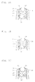
- FIG. 1A to Fig. 1C Three types of sports brassieres of samples a to c illustrated in Fig. 1A to Fig. 1C are used as the samples.
- the position of an under belt 21 is lowest for the sample a, at a middle height for the sample b, and highest for the sample c, in a conventional sports brassiere (see Fig. 1 ).
- An attachment angle ⁇ of shoulder straps 12 is approximately 90° for all the samples.
- a neck line 25 is circular for the samples a and b, and angular for the sample c.
- VICON three-dimensional motion analysis system
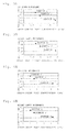
- the movement track for the sample a is shown in Fig. 2A (right breast) and Fig. 2B (left breast). Although the amplitude was different in the other samples b and c, the movement tracks for the samples b and c also showed such tracks (substantially two-leaf forms) as those in Figs. 2A and 2B as a whole form.
- a node J of the movement exists in its central portion, and amplitude parts W1 and W2 extend obliquely upward in a two-leaf pattern on both the right and left sides of the node J.
- Fig. 3A shows a relation between the under-armpit part compression and an up-down movement for the samples a to c
- Fig. 3B shows a relation between the under-armpit part compression and a right-left movement for the samples a to c.
- Fig. 4A shows a relation between the under-chest part compression and the up-down movement for the samples a to c
- Fig. 4B shows a relation between the under-chest part compression and the right-left movement for the samples a to c.
- the under-armpit part compression is less likely to cause compression on the internal organs. If the attachment angle of the shoulder straps 12 is inclined, the tensions of the shoulder straps 12 can be applied to under-armpit parts, and the under-armpit part compression can be locally increased.
- the attachment angle ⁇ of the shoulder straps 12 is appropriately set, whereby the tensions of the shoulder straps 12 are respectively applied so as to obliquely pass through cup parts 17 at the diagonal positions of the shoulder straps 12 to reach the under-armpit parts.
- the under-armpit part compression can be increased, and the movement of the breasts can be effectively suppressed, while compression on the heart, lungs, and the like is avoided.
- the attachment angle ⁇ of the shoulder straps 12 is appropriately set, whereby the tensions of the shoulder straps 12 are concentrated on an under-chest part, and the under-chest part compression is locally increased.
- the attachment angle ⁇ in this case is relatively large, and hence the tensions of the shoulder straps 12 cannot be effectively applied so as to respectively increase the compressions of the side parts of the under belt at the diagonal positions.
- Experiment 2 is intended to examine a relation among the attachment angle ⁇ of the shoulder straps 12, the magnitude of the under-armpit part compression, and movement suppression, in order to embody the idea obtained by Experiment 1 and check technical effects thereof.
- Fig. 5A to Fig. 5E illustrate samples A to E, respectively.
- the basic configuration of each sample is similar to that in a conventional example (see Fig. 11 ), but is different in the attachment angle ⁇ of the shoulder straps 12 in the following manner.
- the angle ⁇ is described using modes of intermediate lines 18 of the shoulder straps 12.
- Sample A The intermediate lines 18 obliquely extend across central portions of the cup parts 17 at the diagonal positions to reach inferior points 20 of anterior axilla points, respectively.
- Sample B The intermediate lines 18 extend to reach the center of the under-chest part on an under-bust line 13.
- Sample C The intermediate lines 18 extend to reach central portions of anterior axillary lines 21, respectively.
- Sample D Similarly to the brassiere disclosed in Patent Literature 4, parts of the shoulder straps are in contact with the insides of the cup parts, and the lower ends of the shoulder straps reach the side parts of the under belt, respectively.
- the intermediate lines 18 extend to reach portions of the under-chest part near inferior points 19 of the bust points at the diagonal positions, respectively.
- Sample E The intermediate lines 18 extend to reach portions of the under-armpit parts immediately therebelow, respectively.
- the under-armpit part compression was measured by putting the samples A to E one after another on the same mannequin that allows compression measurement. Further, the same woman wore the samples A and E, and it was measured how the markers moved during running on the treadmill under the same conditions as those in Experiment 1, whereby the up-down amplitudes and the right-left amplitudes were obtained.
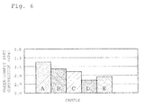
- the under-armpit part compressions for the samples A to E are shown in Fig. 6 .
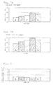
- the up-down amplitudes and the right-left amplitudes therefor are shown in Fig. 7A and Fig. 7B , respectively.
- the under-chest part compressions therefor are shown in Fig. 8 .
- the under-armpit part compression is relatively low (see Fig. 6 ), and the sample A has a superior suppressing effect in the comparison of the samples A and E.
- the intermediate lines 18 of the shoulder straps 12 respectively extend to reach positions away from the side parts 22 of the under belt, and do not reach the side parts 22. This can be considered as a reason why the under-armpit part compression is relatively low.
- sample A is remarkably different from the samples B, C, and D in that the intermediate lines 18 obliquely extend across the centers of the cup parts 17 at the diagonal positions to reach the side parts 22 of the under belt, respectively.
- the under-armpit part compression is increased to some degree, positionally, an influence on the heart, lungs, and the like is small. Further, the range in which the breasts are compressed is limited to a local range along the intermediate lines 18, and the entire breasts are not compressed. Further, the armhole lines 24 can be greatly curved inward along the inclinations of the shoulder straps 12, and hence an overlap with the large skin strain area 30 can be easily avoided.
- each shoulder strap 12 is represented by one intermediate line 18, but the shoulder strap 12 actually has a given width, a belt of spreading tension corresponding to the given width is applied and locally increases the compression of the side part 22 of the under belt through the cup part 17.
- the intermediate line 18 is defined by a line obtained by connecting an intermediate point c1 of a smallest-width portion (in the drawings, the uppermost end) of the shoulder strap 12 to an intermediate point c2 of a width at a position that is away from the smallest-width portion by a given distance in the length direction.
- the tension that is distributed along the intermediate line 18 in a belt-like pattern having the width of the smallest-width portion is considered to locally increase the compression of the side part 22 of the under belt.
- a largest attachment angle ⁇ 1 and a smallest attachment angle ⁇ 2 of the shoulder straps 12 can be set in the following manner. Note that, for ease of description, the following terms are defined.
- X denotes a horizontal line from an anterior axilla point
- Y denotes a midline
- the largest attachment angle ⁇ 1 is defined by an angle of the intermediate line 18 when the medial reference line 27 is in contact with the reference circle 26 in the cup part 17 at the diagonal position of each shoulder strap 12 and when an intersection point d2 between the medial reference line 27 and the under-bust line 13 falls within a range of the side part 22 of the under belt at the diagonal position, the range including the inferior point 19 of the bust point and the inferior point 20 of the anterior axilla point on the under-bust line 13.
- the smallest attachment angle ⁇ 2 is defined by an angle of the intermediate line 18 when the lateral reference line 28 passes through the inside of the reference circle 26 and when an intersection point e2 between the lateral reference line 28 and the under-bust line 13 coincides with the inferior point 20 of the anterior axilla point.
- the tensions of the shoulder straps 12 respectively come out of the reference circles 26 or the side parts 22 of the under belt, so that an effect of suppressing movement of the breasts is decreased. Further, the armhole lines 24 and the neck line 25 cannot be set to be large.
- each armhole line 24 it is desirable that the position of the maximum curvature point 29 of each armhole line 24 be located on the inner side of a point X3 in the large skin strain area 30, on the horizontal line X from the anterior axilla point.
- FIG. 10A and Fig. 10B A specific sports brassiere that is manufactured on the basis of a basic configuration described with reference to Fig. 9 is illustrated in Fig. 10A and Fig. 10B .
- This brassiere includes: the brassiere main body 11 made of a front body 11a for covering a chest and a back body 11b for covering a back; and the right and left shoulder straps 12 provided between the upper end edges of the front body 11a and the back body 11b.
- the under belt 14 is provided at the lower end edge of the brassiere main body 11 with the intermediation of the under-bust line 13.
- the brassiere material may be in any form of woven fabric, knitted fabric, non-woven fabric, and the like.
- the used fibers may be in any form of filament fibers, spun fibers, and the like, and it is possible to use, as appropriate: natural fibers such as cotton, linen, and wool; synthetic fibers such as polyamide fibers, acrylic fibers, and polyolefin fibers; and spandex fibers and the like that are blended and spun, combined into filaments, mixed and woven, or mixed and knitted.
- a pair of the right and left bust points 16 is defined in the front body 11a, and pads are fitted to the rear surface of the brassiere main body 11 with reference to the positions of the bust points 16. Note that, for some brassieres, such pads are not fitted, and hence the pads may be used as needed.
- the attachment angle ⁇ of the shoulder straps 12 to the brassiere main body 11n this case is determined by an inclination angle of the intermediate lines 18 of the shoulder straps 12.
- the intermediate lines 18 in the drawings have such an inclination angle that each intermediate line 18 extends to reach the inferior point 20 of the anterior axilla point on the under-bust line 13.
- the maximum curvature point 29 of each armhole line 24 is set outside of the large skin strain area 30, and both the shoulder straps 12 and the brassiere main body 11 are outside of the large skin strain area 30.
Landscapes
- Engineering & Computer Science (AREA)
- Textile Engineering (AREA)
- Corsets Or Brassieres (AREA)
Abstract
Description
- The present invention relates to a brassiere, and, more particularly, to a brassiere that suppresses movement of breasts during exercise and prevents chafing of a skin of a human body. The present invention is suitably applied to a sports brassiere and the like.
- Suppression of movement of breasts during exercise is required as an important function of sports brassieres, and various sports brassieres each having a movement suppressing function have been known conventionally (Patent Literatures I to 4).
- Such conventional sports brassieres are common in increasing the compressions (compression pressures applied by the brassiere in wear) of cup parts and an under belt and tightening breasts, to thereby suppress movement of the breasts. Such conventional sports brassieres are also common in that shoulder straps are attached to a brassiere main body at a substantially right angle to an under-bust line.
-
Fig. 11 illustrates an example of a conventionally known sports brassiere. This brassiere includes: a brassieremain body 11 made of a front body for covering a chest and a back body for covering a back; and right andleft shoulder straps 12 provided between the upper end edges of the front body and the back body. Anunder belt 14 is provided at the lower end edge of the brassieremain body 11 with the intermediation of an under-bust line 13. -
Bust points 16 are respectively positioned in the right and left of the front body of the brassieremain body 11, and a given range that covers a breast about each of thebust points 16 is referred to as acup part 17. Pads are fitted as appropriate to the rear surface of the brassieremain body 11 with reference to the positions of thebust points 16. An attachment angle θ of theshoulder straps 12 to the brassieremain body 11 is approximately 90°. - According to the conventional sports brassiere configured as described above, the entirety thereof is brought into close contact with a wearer body, the compression of the
cup parts 17 and portions therearound is increased by flexibility of the material thereof, and the breasts are compressed to be thereby suppressed from moving. - Meanwhile,
Patent Literature 4 discloses a front-open type brassiere, in which parts of shoulder straps are in contact with the insides of cup parts, and the lower ends of the shoulder straps reach side parts of the under belt, respectively. - Note that, for ease of the following description, names of other parts of the brassiere than those described above are defined in the following manner.
-
Inferior point 19 of bust point: a point on the under-bust line 13, of a vertical line drawn from thebust point 16 -
Inferior point 20 of anterior axilla point: a point on the under-bust line 13, of an anterioraxillary line 21 -
Side part 22 of under belt: a portion of the underbelt 14 between theinferior point 19 of the bust point and theinferior point 20 of the anterior axilla point -
Front part 23 of under belt: a front central portion of the underbelt 14 between the right and leftinferior points 19 of the bust points -
- Patent Literature 1: Japanese Patent Application Laid-Open No.
2003-221705 - Patent Literature 2: Japanese Patent Application Laid-Open No.
2006-104613 - Patent Literature 3: Japanese Patent Application Laid-Open No.
2009-133027 - Patent Literature 4:
US 5378192 A (the 6th line to the 8th line in the first column, the 18th line in the third column to the 38th line in the fourth column, andFigs. 3 and6 ) - Movement of breasts during exercise provokes extension and damage of Cooper's ligaments inside of the breasts, and causes sagging of the breasts. If the compression of the cup parts or the portions therearound is increased to suppress the movement of the breasts as in the conventional sports brassieres, a heart, lungs, and internal organs are compressed, which is not desirable. Further, if the compression of the cup parts or the under belt is excessive, the positions and forms of various parts of the internal organs may be unfavorably changed.
- Moreover, in the conventional structure, a wide region ranging over the
cup parts 17 and the portions therearound is tightened, and the attachment angle θ of theshoulder straps 12 to the brassieremain body 11 is substantially 90°. Hence, a large portion of the brassiere in the conventional structure overlaps with a largeskin strain area 30 during exercise. For this reason, chafing of a skin is likely to occur, and the brassieremain body 11 is likely to be slid upward in the course of the exercise. - Similarly in the brassiere described in
Patent Literature 4, the shoulder straps only pass through extremely small portions inside of the cup parts. Hence, an effect of obliquely holding breasts is small, and almost no effect of suppressing movement of the breasts is produced. - Note that the large
skin strain area 30 refers to a triangular range surrounded by points X1, X2, and X3 in the drawings. X1 denotes an acromion, X2 denotes an anterior axilla point, and X3 denotes a point at 3/5 of a distance L from the anterior axilla point X2, the distance L being a distance between: the anterior axilla point X2; and an intersection point X4 between a horizontal line X from the anterior axilla point and a midline Y. - In view of the above, the present invention has an object to produce an effect of suppressing movement of breasts while limiting a range in which the breasts are compressed, to thereby reduce compression on various parts of internal organs such as a heart and lungs, the breasts, and the like and, at the same time, eliminate an overlap range with a large skin strain area during exercise, thus preventing chafing of a skin.
- In order to solve the above-mentioned problems, the present invention provides a brassiere including: a brassiere main body made of a front body for covering a chest and a back body for covering a back; right and left shoulder straps provided between upper end edges of the front body and the back body; an under belt that is provided at a lower end edge of the brassiere main body with an intermediation of an under-bust line; and a pair of right and left cup parts provided in the front body. An attachment angle of the shoulder straps to the brassiere main body is defined by such an angle that an intermediate line of each shoulder strap extends to pass through a central portion of the cup part at a diagonal position of the shoulder strap and reach a range including an inferior point of a bust point and an inferior point of an anterior axilla point on the under-bust line.
- In the present invention, an outer circumferential circle of the cup part is defined by a circle having a radius that is a distance between the bust point in a center of the cup part and the inferior point of the bust point on the under-bust line, and a range of the central portion of the cup part is defined by a concentric reference circle having a radius that is 0.6 times the radius of the cup part.
- Specifically, an inclination angle of the intermediate line to the under-bust line falls within a range between a largest inclination angle θ1 defined below in (1) and a smallest inclination angle θ2 defined below in (2):
- (1) the largest inclination angle θ1 is defined by such an angle that the intermediate line that passes on an inner side of the bust point of the cup part at the diagonal position extends to come into contact with the reference circle or pass through an inside of the reference circle and reach the range including the inferior point of the bust point and the inferior point of the anterior axilla point on the under-bust line; and
- (2) the smallest inclination angle θ2 is defined by such an angle that the intermediate line that passes on an outer side of the bust point of the cup part at the diagonal position or passes through the bust point extends to come into contact with the reference circle or pass through the inside of the reference circle and reach the range including the inferior point of the bust point and the inferior point of the anterior axilla point on the under-bust line.
- Alternatively, an inclination angle of the intermediate line to the under-bust line may fall within a range between a largest inclination angle θ1 defined below in (1) and a smallest inclination angle θ2 defined below in (2):
- (1) the largest inclination angle θ1 is defined by such an angle that the intermediate line that passes on an inner side of the bust point of the cup part at the diagonal position extends to come into contact with the reference circle or pass through an inside of the reference circle and reach the inferior point of the bust point on the under-bust line; and
- (2) the smallest inclination angle θ2 is defined by such an angle that the intermediate line that passes on the inner side of the bust point of the cup part at the diagonal position extends to come into contact with the reference circle or pass through the inside of the reference circle and reach the inferior point of the anterior axilla point on the under-bust line.
- Further, a medial reference line that passes through a medial point of a smallest-width portion of the shoulder strap and is parallel to the intermediate line that defines the largest inclination angle θ1 passes through the inside of the reference circle along this intermediate line, and a lateral reference line that passes through a lateral point of the smallest-width portion of the shoulder strap and is parallel to the intermediate line that defines the smallest inclination angle θ2 passes through the inside of the reference circle along this intermediate line.
- Further, an armhole is formed between a lateral edge of each shoulder strap and the upper end edge of the front body, and a maximum curvature point of the armhole is set on an inner side of a point at 3/5 of a distance from the anterior axilla point to a midline, on a horizontal line from the anterior axilla point.
- The attachment angle of the shoulder straps to the brassiere main body is defined as described above, whereby an obliquely acting tension is partially applied to each side part of the under belt across the cup part located at the diagonal position of each shoulder strap (the cup part at the diagonal position with respect to each shoulder strap), with the result that movement of breasts is suppressed.
- The attachment angle of the shoulder straps is more greatly inclined in a direction in which the lower end thereof approaches the midline of a wearer body, compared with conventional cases. Accordingly, an armhole can be formed so as to be greatly curved along each shoulder strap thus configured, and an overlap with a large skin strain area can be avoided.
- As described above, the brassiere of the present invention can locally increase the compression of the side parts of the under belt at the respective diagonal positions by means of the tensions of the shoulder straps, to thereby suppress movement of breasts. Although the compression of the side parts of the under belt is increased, the compression of the under-chest part does not need to be increased, and the compression applied to the breasts is partial. Hence, compression on a heart, lungs, and various parts of internal organs is reduced.
- Further, the armholes can be formed at positions that do not overlap with the large skin strain area. Hence, chafing of a skin is prevented, the degree of freedom in motion such as an arm swing is increased, and the brassiere main body is prevented from sliding up due to a motion.
- Accordingly, the brassiere of the present invention is suitably applied to sports.
-
-
Fig. 1A is a front view illustrating a wear state of a sample a inExperiment 1. -
Fig. 1B is a front view illustrating a wear state of a sample b inExperiment 1. -
Fig. 1C is a front view illustrating a wear state of a sample c inExperiment 1. -
Fig. 2A shows a movement track of a right breast. -
Fig. 2B shows a movement track of a left breast. -
Fig. 3A is a graph showing a relation between an under-armpit part compression and an up-down movement. -
Fig. 3B is a graph showing a relation between the under-armpit part compression and a right-left movement. -
Fig. 4A is a graph showing a relation between an under-chest part compression and the up-down movement. -
Fig. 4B is a graph showing a relation between the under-chest part compression and the right-left movement. -
Fig. 5A is a front view illustrating a wear state of a sample A inExperiment 2. -
Fig. 5B is a front view illustrating a wear state of a sample B inExperiment 2. -
Fig. 5C is a front view illustrating a wear state of a sample C inExperiment 2. -
Fig. 5D is a front view illustrating a wear state of a sample D inExperiment 2. -
Fig. 5E is a front view illustrating a wear state of a sample E inExperiment 2. -
Fig. 6 is a graph showing measurement results of the under-armpit part compression. -
Fig. 7A is a graph showing measurement results of the up-down movement. -
Fig. 7B is a graph showing measurement results of the right-left movement. -
Fig. 8 is a graph showing measurement results of the under-chest part compression. -
Fig. 9 is a front view illustrating a brassiere inEmbodiment 1. -
Fig. 10A is a front view illustrating a wear state of the brassiere inEmbodiment 1. -
Fig. 10B is a rear view ofFig. 10A . -
Fig. 11 is a front view illustrating a wear state in a conventional example. - Experiments from conceiving of the present invention to completion thereof are first described as [Experiment 1] and [Experiment 2], and a specific embodiment of the present invention is then described as [Embodiment 1].
- The experiment is intended to know a relation between: movement of breasts; and an under-armpit part compression and an under-chest part compression.
- Three types of sports brassieres of samples a to c illustrated in
Fig. 1A to Fig. 1C are used as the samples. Among these samples, the position of an underbelt 21 is lowest for the sample a, at a middle height for the sample b, and highest for the sample c, in a conventional sports brassiere (seeFig. 1 ). An attachment angle θ ofshoulder straps 12 is approximately 90° for all the samples. Aneck line 25 is circular for the samples a and b, and angular for the sample c. - The same woman who wore the samples a to c one after another ran at 9 km/h on a treadmill in the state where markers were respectively added to bust
points 16, and how the markers moved at that time was measured using a three-dimensional motion analysis system (VICON), on the basis of a fossa jugularis (an intersection point between: a straight line connecting upper sternal ends of right and left collarbones; and a midline) as a reference point. - The movement track for the sample a is shown in
Fig. 2A (right breast) andFig. 2B (left breast). Although the amplitude was different in the other samples b and c, the movement tracks for the samples b and c also showed such tracks (substantially two-leaf forms) as those inFigs. 2A and 2B as a whole form. In this track, a node J of the movement exists in its central portion, and amplitude parts W1 and W2 extend obliquely upward in a two-leaf pattern on both the right and left sides of the node J. -
Fig. 3A shows a relation between the under-armpit part compression and an up-down movement for the samples a to c, andFig. 3B shows a relation between the under-armpit part compression and a right-left movement for the samples a to c. -
Fig. 4A shows a relation between the under-chest part compression and the up-down movement for the samples a to c, andFig. 4B shows a relation between the under-chest part compression and the right-left movement for the samples a to c. - (1) The experiment results showed that, for the sample a, both the under-armpit part compression and the under-chest part compression were largest, and the amplitude was smallest (in other words, a movement suppressing effect was highest).
- Considering the positions at which the breasts are compressed, it is apparent that the under-chest part compression is more likely to cause compression on a heart, lungs, and various parts of internal organs, compared with the under-armpit part compression.
- In contrast, the under-armpit part compression is less likely to cause compression on the internal organs. If the attachment angle of the shoulder straps 12 is inclined, the tensions of the shoulder straps 12 can be applied to under-armpit parts, and the under-armpit part compression can be locally increased.
- The following idea is obtained on the basis of the above considerations. That is, the attachment angle θ of the shoulder straps 12 is appropriately set, whereby the tensions of the shoulder straps 12 are respectively applied so as to obliquely pass through
cup parts 17 at the diagonal positions of theshoulder straps 12 to reach the under-armpit parts. As a result, the under-armpit part compression can be increased, and the movement of the breasts can be effectively suppressed, while compression on the heart, lungs, and the like is avoided. - Note that the following measures can be conceived as a comparison with the above-mentioned idea. That is, the attachment angle θ of the shoulder straps 12 is appropriately set, whereby the tensions of the shoulder straps 12 are concentrated on an under-chest part, and the under-chest part compression is locally increased. However, the attachment angle θ in this case is relatively large, and hence the tensions of the shoulder straps 12 cannot be effectively applied so as to respectively increase the compressions of the side parts of the under belt at the diagonal positions.
- (2) Because the attachment angle of the shoulder straps 12 is substantially 90° for all the samples a to c,
armhole lines 24 cannot be set to be large. Hence, an overlap range with a large skin strain area 30 (seeFig. 11 ) during exercise is large, and chafing of a skin may occur in the large range. Further, a brassieremain body 11 tends to slide up together with skin expansion/contraction. -
Experiment 2 is intended to examine a relation among the attachment angle θ of the shoulder straps 12, the magnitude of the under-armpit part compression, and movement suppression, in order to embody the idea obtained byExperiment 1 and check technical effects thereof. -
Fig. 5A to Fig. 5E illustrate samples A to E, respectively. The basic configuration of each sample is similar to that in a conventional example (seeFig. 11 ), but is different in the attachment angle θ of the shoulder straps 12 in the following manner. The angle θ is described using modes ofintermediate lines 18 of the shoulder straps 12. - Sample A: The
intermediate lines 18 obliquely extend across central portions of thecup parts 17 at the diagonal positions to reachinferior points 20 of anterior axilla points, respectively. - Sample B: The
intermediate lines 18 extend to reach the center of the under-chest part on an under-bust line 13. - Sample C: The
intermediate lines 18 extend to reach central portions of anterioraxillary lines 21, respectively. - Sample D: Similarly to the brassiere disclosed in
Patent Literature 4, parts of the shoulder straps are in contact with the insides of the cup parts, and the lower ends of the shoulder straps reach the side parts of the under belt, respectively. Theintermediate lines 18 extend to reach portions of the under-chest part nearinferior points 19 of the bust points at the diagonal positions, respectively. - Sample E: The
intermediate lines 18 extend to reach portions of the under-armpit parts immediately therebelow, respectively. - The under-armpit part compression was measured by putting the samples A to E one after another on the same mannequin that allows compression measurement. Further, the same woman wore the samples A and E, and it was measured how the markers moved during running on the treadmill under the same conditions as those in
Experiment 1, whereby the up-down amplitudes and the right-left amplitudes were obtained. - The under-armpit part compressions for the samples A to E are shown in
Fig. 6 . The up-down amplitudes and the right-left amplitudes therefor are shown inFig. 7A and Fig. 7B , respectively. The under-chest part compressions therefor are shown inFig. 8 . - With regard to a relation between the modes of the
intermediate lines 18, that is, the attachment angle θ of the shoulder straps 12 and the under-armpit part compression, if the angle θ is relatively large (the samples B, D, and E) and if the angle θ is relatively small (the sample C), the under-armpit part compression is relatively low (seeFig. 6 ), and the sample A has a superior suppressing effect in the comparison of the samples A and E. For the samples B to E, theintermediate lines 18 of the shoulder straps 12 respectively extend to reach positions away from theside parts 22 of the under belt, and do not reach theside parts 22. This can be considered as a reason why the under-armpit part compression is relatively low. - In contrast, the sample A is remarkably different from the samples B, C, and D in that the
intermediate lines 18 obliquely extend across the centers of thecup parts 17 at the diagonal positions to reach theside parts 22 of the under belt, respectively. - In the case of the sample A, even if the under-armpit part compression is increased to some degree, positionally, an influence on the heart, lungs, and the like is small. Further, the range in which the breasts are compressed is limited to a local range along the
intermediate lines 18, and the entire breasts are not compressed. Further, thearmhole lines 24 can be greatly curved inward along the inclinations of the shoulder straps 12, and hence an overlap with the largeskin strain area 30 can be easily avoided. - For more information, measurement results of the under-chest compressions for the samples A and E are shown in
Fig. 8 . The samples A and E exhibited similar low values. - Note that
Experiment 2 is described in the state where on-shoulder portions of the shoulder straps 12 are fixed to given positions, but the positions are each set as appropriate within a shoulder width range. - It is examined as to which range is preferable for the attachment angle θ of the shoulder straps 12 in the case where a sports brassiere having a preferable structure is manufactured on the basis of
Experiment 1 andExperiment 2 described above. - In
Experiment 1 andExperiment 2, the tension of eachshoulder strap 12 is represented by oneintermediate line 18, but theshoulder strap 12 actually has a given width, a belt of spreading tension corresponding to the given width is applied and locally increases the compression of theside part 22 of the under belt through thecup part 17. - Accordingly, as illustrated in
Fig. 9 , theintermediate line 18 is defined by a line obtained by connecting an intermediate point c1 of a smallest-width portion (in the drawings, the uppermost end) of theshoulder strap 12 to an intermediate point c2 of a width at a position that is away from the smallest-width portion by a given distance in the length direction. The tension that is distributed along theintermediate line 18 in a belt-like pattern having the width of the smallest-width portion is considered to locally increase the compression of theside part 22 of the under belt. - Considering the results of
Experiment 2, if theintermediate line 18 is excessively away from the central portion of thecup part 17, that is, thebust point 16, a movement suppressing effect is impaired. Accordingly, in order to exclude, from the targets, theintermediate lines 18 that pass through portions away from the central portion by a given distance or more, a concentric circle having a radius that is 0.6 times a radius a of thecup part 17 is set as areference circle 26. The value of 0.6 times is empirically determined considering that the tensions of the shoulder straps 12 can reach the movement track ranges inFig. 2A and Fig. 2B . - On the basis of the above considerations, a largest attachment angle θ1 and a smallest attachment angle θ2 of the shoulder straps 12 can be set in the following manner. Note that, for ease of description, the following terms are defined.
- · Medial reference line 27: a line that passes through a medial point d1 of the smallest-width portion of the
shoulder strap 12 and is parallel to theintermediate line 18 - · Lateral reference line 28: a line that passes through a lateral point e1 of the smallest-width portion of the
shoulder strap 12 and is parallel to theintermediate line 18 - Note that, in the drawings, X denotes a horizontal line from an anterior axilla point, and Y denotes a midline.
- The largest attachment angle θ1 is defined by an angle of the
intermediate line 18 when themedial reference line 27 is in contact with thereference circle 26 in thecup part 17 at the diagonal position of eachshoulder strap 12 and when an intersection point d2 between themedial reference line 27 and the under-bust line 13 falls within a range of theside part 22 of the under belt at the diagonal position, the range including theinferior point 19 of the bust point and theinferior point 20 of the anterior axilla point on the under-bust line 13. - The smallest attachment angle θ2 is defined by an angle of the
intermediate line 18 when thelateral reference line 28 passes through the inside of thereference circle 26 and when an intersection point e2 between thelateral reference line 28 and the under-bust line 13 coincides with theinferior point 20 of the anterior axilla point. - If the attachment angle of the shoulder straps 12 falls outside of the range between the angles θ1 and θ2, the tensions of the shoulder straps 12 respectively come out of the reference circles 26 or the
side parts 22 of the under belt, so that an effect of suppressing movement of the breasts is decreased. Further, thearmhole lines 24 and theneck line 25 cannot be set to be large. - It is desirable that the position of the
maximum curvature point 29 of eacharmhole line 24 be located on the inner side of a point X3 in the largeskin strain area 30, on the horizontal line X from the anterior axilla point. - A specific sports brassiere that is manufactured on the basis of a basic configuration described with reference to
Fig. 9 is illustrated inFig. 10A and Fig. 10B . This brassiere includes: the brassieremain body 11 made of afront body 11a for covering a chest and aback body 11b for covering a back; and the right andleft shoulder straps 12 provided between the upper end edges of thefront body 11a and theback body 11b. The underbelt 14 is provided at the lower end edge of the brassieremain body 11 with the intermediation of the under-bust line 13. The brassiere material may be in any form of woven fabric, knitted fabric, non-woven fabric, and the like. Further, the used fibers may be in any form of filament fibers, spun fibers, and the like, and it is possible to use, as appropriate: natural fibers such as cotton, linen, and wool; synthetic fibers such as polyamide fibers, acrylic fibers, and polyolefin fibers; and spandex fibers and the like that are blended and spun, combined into filaments, mixed and woven, or mixed and knitted. - A pair of the right and left bust points 16 is defined in the
front body 11a, and pads are fitted to the rear surface of the brassieremain body 11 with reference to the positions of the bust points 16. Note that, for some brassieres, such pads are not fitted, and hence the pads may be used as needed. - The attachment angle θ of the
shoulder straps 12 to the brassiere main body 11n this case is determined by an inclination angle of theintermediate lines 18 of the shoulder straps 12. Theintermediate lines 18 in the drawings have such an inclination angle that eachintermediate line 18 extends to reach theinferior point 20 of the anterior axilla point on the under-bust line 13. - The
maximum curvature point 29 of eacharmhole line 24 is set outside of the largeskin strain area 30, and both the shoulder straps 12 and the brassieremain body 11 are outside of the largeskin strain area 30. -
- d1
- medial point
- d2
- intersection point
- e1
- lateral point
- e2
- intersection point
- θ
- attachment angle
- X
- horizontal line from anterior axilla point
- Y
- midline
- 11
- brassiere main body
- 11a
- front body
- 11b
- back body
- 12
- shoulder strap
- 13
- under-bust line
- 14
- under belt
- 16
- bust point
- 17
- cup part
- 18
- intermediate line
- 19
- inferior point of bust point
- 20
- inferior point of anterior axilla point
- 21
- anterior axillary line
- 22
- side part of under belt
- 23
- front part of under belt
- 24
- armhole line
- 25
- neck line
- 26
- reference circle
- 27
- medial reference line
- 28
- lateral reference line
- 29
- maximum curvature point
- 30
- large skin strain area
Claims (7)
- A brassiere comprising:a brassiere main body made of a front body for covering a chest and a back body for covering a back;right and left shoulder straps provided between upper end edges of the front body and the back body;an under belt that is provided at a lower end edge of the brassiere main body with an intermediation of an under-bust line; anda pair of right and left cup parts provided in the front body, whereinan attachment angle of the shoulder straps to the brassiere main body is defined by such an angle that an intermediate line of each shoulder strap extends to pass through a central portion of the cup part at a diagonal position of the shoulder strap and reach a range including an inferior point of a bust point and an inferior point of an anterior axilla point on the under-bust line.
- The brassiere according to claim 1, being used for sports.
- The brassiere according to claim 1 or 2, wherein
an outer circumferential circle of the cup part is defined by a circle having a radius that is a distance between the bust point in a center of the cup part and the inferior point of the bust point on the under-bust line, and
a range of the central portion of the cup part is defined by a concentric reference circle having a radius that is 0.6 times the radius of the cup part. - The brassiere according to any of claims 1 to 3, wherein
an inclination angle of the intermediate line to the under-bust line falls within a range between a largest inclination angle θ1 defined below in (1) and a smallest inclination angle θ2 defined below in (2):(1) the largest inclination angle θ1 is defined by such an angle that the intermediate line that passes on an inner side of the bust point of the cup part at the diagonal position extends to come into contact with the reference circle or pass through an inside of the reference circle and reach the range including the inferior point of the bust point and the inferior point of the anterior axilla point on the under-bust line; and(2) the smallest inclination angle θ2 is defined by such an angle that the intermediate line that passes on an outer side of the bust point of the cup part at the diagonal position or passes through the bust point extends to come into contact with the reference circle or pass through the inside of the reference circle and reach the range including the inferior point of the bust point and the inferior point of the anterior axilla point on the under-bust line. - The brassiere according to any of claims 1 to 3, wherein
an inclination angle of the intermediate line to the under-bust line falls within a range between a largest inclination angle θ1 defined below in (1) and a smallest inclination angle θ2 defined below in (2):(1) the largest inclination angle θ1 is defined by such an angle that the intermediate line that passes on an inner side of the bust point of the cup part at the diagonal position extends to come into contact with the reference circle or pass through an inside of the reference circle and reach the inferior point of the bust point on the under-bust line; and(2) the smallest inclination angle θ2 is defined by such an angle that the intermediate line that passes on the inner side of the bust point of the cup part at the diagonal position extends to come into contact with the reference circle or pass through the inside of the reference circle and reach the inferior point of the anterior axilla point on the under-bust line. - The brassiere according to claim 4 or 5, wherein
a medial reference line that passes through a medial point of a smallest-width portion of the shoulder strap and is parallel to the intermediate line that defines the largest inclination angle θ1 passes through the inside of the reference circle along this intermediate line, and
a lateral reference line that passes through a lateral point of the smallest-width portion of the shoulder strap and is parallel to the intermediate line that defines the smallest inclination angle θ2 passes through the inside of the reference circle along this intermediate line. - The brassiere according to any of claims 1 to 6, wherein
an armhole is formed between a lateral edge of each shoulder strap and the upper end edge of the front body, and
a maximum curvature point of the armhole is set on an inner side of a point at 3/5 of a distance from the anterior axilla point to a midline, on a horizontal line from the anterior axilla point.
Applications Claiming Priority (2)
| Application Number | Priority Date | Filing Date | Title |
|---|---|---|---|
| PCT/JP2011/057844 WO2012131910A1 (en) | 2011-03-29 | 2011-03-29 | Brazier |
| PCT/JP2012/057916 WO2012133397A1 (en) | 2011-03-29 | 2012-03-27 | Brazier |
Publications (3)
| Publication Number | Publication Date |
|---|---|
| EP2692257A1 true EP2692257A1 (en) | 2014-02-05 |
| EP2692257A4 EP2692257A4 (en) | 2016-11-23 |
| EP2692257B1 EP2692257B1 (en) | 2018-08-08 |
Family
ID=46929741
Family Applications (1)
| Application Number | Title | Priority Date | Filing Date |
|---|---|---|---|
| EP12765122.2A Active EP2692257B1 (en) | 2011-03-29 | 2012-03-27 | Brassiere |
Country Status (3)
| Country | Link |
|---|---|
| EP (1) | EP2692257B1 (en) |
| JP (1) | JP5559931B2 (en) |
| WO (2) | WO2012131910A1 (en) |
Families Citing this family (3)
| Publication number | Priority date | Publication date | Assignee | Title |
|---|---|---|---|---|
| SE1300440A1 (en) * | 2013-06-20 | 2014-12-21 | Yajlee Ab | Brackets, especially for sports use or convalescence after surgery |
| US11134724B2 (en) | 2016-04-06 | 2021-10-05 | Nike, Inc. | Engineered bra |
| KR200489799Y1 (en) * | 2018-11-16 | 2019-08-09 | 주식회사 케이앤디인터내셔널 | Breast correction underwear |
Family Cites Families (9)
| Publication number | Priority date | Publication date | Assignee | Title |
|---|---|---|---|---|
| GB2183144B (en) * | 1985-11-25 | 1989-10-04 | Dansport International Ltd | Brassiere |
| US5378192A (en) * | 1993-10-04 | 1995-01-03 | Darmante; Dale T. | Custom-fit front-opening brassiere |
| JPH07207503A (en) * | 1994-01-18 | 1995-08-08 | Sanae Kamo | bra |
| US5897422A (en) * | 1998-05-13 | 1999-04-27 | Mcgee; Marguerite K. | Brassiere |
| JP2000220005A (en) * | 1999-01-29 | 2000-08-08 | Mizuno Corp | Sport brassiere |
| JP3884296B2 (en) | 2002-01-30 | 2007-02-21 | 美津濃株式会社 | Women's clothing |
| JP4688464B2 (en) | 2004-10-05 | 2011-05-25 | 美津濃株式会社 | Sports clothing |
| JP2009133027A (en) | 2007-11-30 | 2009-06-18 | Rushian:Kk | Sport brassiere |
| JP3159452U (en) * | 2010-03-02 | 2010-05-20 | 富士紡ホールディングス株式会社 | Half top |
-
2011
- 2011-03-29 WO PCT/JP2011/057844 patent/WO2012131910A1/en not_active Ceased
-
2012
- 2012-03-27 JP JP2013507605A patent/JP5559931B2/en not_active Expired - Fee Related
- 2012-03-27 WO PCT/JP2012/057916 patent/WO2012133397A1/en not_active Ceased
- 2012-03-27 EP EP12765122.2A patent/EP2692257B1/en active Active
Also Published As
| Publication number | Publication date |
|---|---|
| EP2692257B1 (en) | 2018-08-08 |
| EP2692257A4 (en) | 2016-11-23 |
| WO2012131910A1 (en) | 2012-10-04 |
| WO2012133397A1 (en) | 2012-10-04 |
| JPWO2012133397A1 (en) | 2014-07-28 |
| JP5559931B2 (en) | 2014-07-23 |
Similar Documents
| Publication | Publication Date | Title |
|---|---|---|
| EP3597061B1 (en) | Brassiere | |
| US8585458B2 (en) | Natural support garment | |
| EP2692255B1 (en) | Garment having cup portions | |
| US20190008214A1 (en) | Support garment having adjustable lifting straps and cinching cup | |
| US20190082749A1 (en) | Pressure-distributing undergarment with fastening system | |
| US9913498B2 (en) | Garment with cups | |
| EP2692257B1 (en) | Brassiere | |
| EP4340664B1 (en) | Athletic bra | |
| KR20190001694U (en) | Brassiere | |
| US20160037829A1 (en) | Method and apparatus for improved bra | |
| JP4260101B2 (en) | Upper underwear | |
| US20220361592A1 (en) | Sports bra with impact padding | |
| TWI738487B (en) | bra | |
| KR200474812Y1 (en) | Brassiere | |
| JP2003221705A (en) | Women's clothing | |
| CN103300490A (en) | Cloth with bra | |
| CN112586812A (en) | High-support-degree double-shoulder-strap adjustable sports underwear | |
| US20220071313A1 (en) | Bra Having Wide Under Band Hem and Manufacturing Method Thereof | |
| CN217722721U (en) | Hang neck formula sports underwear | |
| CN217136867U (en) | Double-layer wrapped sports underwear | |
| CN108143018A (en) | A kind of Multifunction nursing brassiere | |
| CN210382679U (en) | Gather together formula brassiere | |
| CN209498609U (en) | Brassiere | |
| CN109419052A (en) | Corset integral type Bra for nursing | |
| JP2001159003A (en) | Women's shirts |
Legal Events
| Date | Code | Title | Description |
|---|---|---|---|
| PUAI | Public reference made under article 153(3) epc to a published international application that has entered the european phase |
Free format text: ORIGINAL CODE: 0009012 |
|
| 17P | Request for examination filed |
Effective date: 20131028 |
|
| AK | Designated contracting states |
Kind code of ref document: A1 Designated state(s): AL AT BE BG CH CY CZ DE DK EE ES FI FR GB GR HR HU IE IS IT LI LT LU LV MC MK MT NL NO PL PT RO RS SE SI SK SM TR |
|
| DAX | Request for extension of the european patent (deleted) | ||
| RA4 | Supplementary search report drawn up and despatched (corrected) |
Effective date: 20161020 |
|
| RIC1 | Information provided on ipc code assigned before grant |
Ipc: A41C 3/12 20060101AFI20161014BHEP Ipc: A41C 3/00 20060101ALI20161014BHEP |
|
| RIC1 | Information provided on ipc code assigned before grant |
Ipc: A41C 3/00 20060101ALI20171218BHEP Ipc: A41C 3/12 20060101AFI20171218BHEP |
|
| GRAP | Despatch of communication of intention to grant a patent |
Free format text: ORIGINAL CODE: EPIDOSNIGR1 |
|
| STAA | Information on the status of an ep patent application or granted ep patent |
Free format text: STATUS: GRANT OF PATENT IS INTENDED |
|
| INTG | Intention to grant announced |
Effective date: 20180309 |
|
| GRAS | Grant fee paid |
Free format text: ORIGINAL CODE: EPIDOSNIGR3 |
|
| GRAA | (expected) grant |
Free format text: ORIGINAL CODE: 0009210 |
|
| STAA | Information on the status of an ep patent application or granted ep patent |
Free format text: STATUS: THE PATENT HAS BEEN GRANTED |
|
| AK | Designated contracting states |
Kind code of ref document: B1 Designated state(s): AL AT BE BG CH CY CZ DE DK EE ES FI FR GB GR HR HU IE IS IT LI LT LU LV MC MK MT NL NO PL PT RO RS SE SI SK SM TR |
|
| REG | Reference to a national code |
Ref country code: GB Ref legal event code: FG4D |
|
| REG | Reference to a national code |
Ref country code: CH Ref legal event code: EP Ref country code: AT Ref legal event code: REF Ref document number: 1025981 Country of ref document: AT Kind code of ref document: T Effective date: 20180815 |
|
| REG | Reference to a national code |
Ref country code: IE Ref legal event code: FG4D |
|
| REG | Reference to a national code |
Ref country code: DE Ref legal event code: R096 Ref document number: 602012049504 Country of ref document: DE |
|
| REG | Reference to a national code |
Ref country code: NL Ref legal event code: MP Effective date: 20180808 |
|
| REG | Reference to a national code |
Ref country code: LT Ref legal event code: MG4D |
|
| REG | Reference to a national code |
Ref country code: AT Ref legal event code: MK05 Ref document number: 1025981 Country of ref document: AT Kind code of ref document: T Effective date: 20180808 |
|
| PG25 | Lapsed in a contracting state [announced via postgrant information from national office to epo] |
Ref country code: SE Free format text: LAPSE BECAUSE OF FAILURE TO SUBMIT A TRANSLATION OF THE DESCRIPTION OR TO PAY THE FEE WITHIN THE PRESCRIBED TIME-LIMIT Effective date: 20180808 Ref country code: NO Free format text: LAPSE BECAUSE OF FAILURE TO SUBMIT A TRANSLATION OF THE DESCRIPTION OR TO PAY THE FEE WITHIN THE PRESCRIBED TIME-LIMIT Effective date: 20181108 Ref country code: GR Free format text: LAPSE BECAUSE OF FAILURE TO SUBMIT A TRANSLATION OF THE DESCRIPTION OR TO PAY THE FEE WITHIN THE PRESCRIBED TIME-LIMIT Effective date: 20181109 Ref country code: FI Free format text: LAPSE BECAUSE OF FAILURE TO SUBMIT A TRANSLATION OF THE DESCRIPTION OR TO PAY THE FEE WITHIN THE PRESCRIBED TIME-LIMIT Effective date: 20180808 Ref country code: RS Free format text: LAPSE BECAUSE OF FAILURE TO SUBMIT A TRANSLATION OF THE DESCRIPTION OR TO PAY THE FEE WITHIN THE PRESCRIBED TIME-LIMIT Effective date: 20180808 Ref country code: IS Free format text: LAPSE BECAUSE OF FAILURE TO SUBMIT A TRANSLATION OF THE DESCRIPTION OR TO PAY THE FEE WITHIN THE PRESCRIBED TIME-LIMIT Effective date: 20181208 Ref country code: PL Free format text: LAPSE BECAUSE OF FAILURE TO SUBMIT A TRANSLATION OF THE DESCRIPTION OR TO PAY THE FEE WITHIN THE PRESCRIBED TIME-LIMIT Effective date: 20180808 Ref country code: AT Free format text: LAPSE BECAUSE OF FAILURE TO SUBMIT A TRANSLATION OF THE DESCRIPTION OR TO PAY THE FEE WITHIN THE PRESCRIBED TIME-LIMIT Effective date: 20180808 Ref country code: BG Free format text: LAPSE BECAUSE OF FAILURE TO SUBMIT A TRANSLATION OF THE DESCRIPTION OR TO PAY THE FEE WITHIN THE PRESCRIBED TIME-LIMIT Effective date: 20181108 Ref country code: NL Free format text: LAPSE BECAUSE OF FAILURE TO SUBMIT A TRANSLATION OF THE DESCRIPTION OR TO PAY THE FEE WITHIN THE PRESCRIBED TIME-LIMIT Effective date: 20180808 Ref country code: LT Free format text: LAPSE BECAUSE OF FAILURE TO SUBMIT A TRANSLATION OF THE DESCRIPTION OR TO PAY THE FEE WITHIN THE PRESCRIBED TIME-LIMIT Effective date: 20180808 |
|
| PG25 | Lapsed in a contracting state [announced via postgrant information from national office to epo] |
Ref country code: AL Free format text: LAPSE BECAUSE OF FAILURE TO SUBMIT A TRANSLATION OF THE DESCRIPTION OR TO PAY THE FEE WITHIN THE PRESCRIBED TIME-LIMIT Effective date: 20180808 Ref country code: LV Free format text: LAPSE BECAUSE OF FAILURE TO SUBMIT A TRANSLATION OF THE DESCRIPTION OR TO PAY THE FEE WITHIN THE PRESCRIBED TIME-LIMIT Effective date: 20180808 Ref country code: HR Free format text: LAPSE BECAUSE OF FAILURE TO SUBMIT A TRANSLATION OF THE DESCRIPTION OR TO PAY THE FEE WITHIN THE PRESCRIBED TIME-LIMIT Effective date: 20180808 |
|
| PG25 | Lapsed in a contracting state [announced via postgrant information from national office to epo] |
Ref country code: EE Free format text: LAPSE BECAUSE OF FAILURE TO SUBMIT A TRANSLATION OF THE DESCRIPTION OR TO PAY THE FEE WITHIN THE PRESCRIBED TIME-LIMIT Effective date: 20180808 Ref country code: ES Free format text: LAPSE BECAUSE OF FAILURE TO SUBMIT A TRANSLATION OF THE DESCRIPTION OR TO PAY THE FEE WITHIN THE PRESCRIBED TIME-LIMIT Effective date: 20180808 Ref country code: CZ Free format text: LAPSE BECAUSE OF FAILURE TO SUBMIT A TRANSLATION OF THE DESCRIPTION OR TO PAY THE FEE WITHIN THE PRESCRIBED TIME-LIMIT Effective date: 20180808 Ref country code: RO Free format text: LAPSE BECAUSE OF FAILURE TO SUBMIT A TRANSLATION OF THE DESCRIPTION OR TO PAY THE FEE WITHIN THE PRESCRIBED TIME-LIMIT Effective date: 20180808 Ref country code: IT Free format text: LAPSE BECAUSE OF FAILURE TO SUBMIT A TRANSLATION OF THE DESCRIPTION OR TO PAY THE FEE WITHIN THE PRESCRIBED TIME-LIMIT Effective date: 20180808 |
|
| REG | Reference to a national code |
Ref country code: DE Ref legal event code: R097 Ref document number: 602012049504 Country of ref document: DE |
|
| PG25 | Lapsed in a contracting state [announced via postgrant information from national office to epo] |
Ref country code: SK Free format text: LAPSE BECAUSE OF FAILURE TO SUBMIT A TRANSLATION OF THE DESCRIPTION OR TO PAY THE FEE WITHIN THE PRESCRIBED TIME-LIMIT Effective date: 20180808 Ref country code: SM Free format text: LAPSE BECAUSE OF FAILURE TO SUBMIT A TRANSLATION OF THE DESCRIPTION OR TO PAY THE FEE WITHIN THE PRESCRIBED TIME-LIMIT Effective date: 20180808 Ref country code: DK Free format text: LAPSE BECAUSE OF FAILURE TO SUBMIT A TRANSLATION OF THE DESCRIPTION OR TO PAY THE FEE WITHIN THE PRESCRIBED TIME-LIMIT Effective date: 20180808 |
|
| PLBE | No opposition filed within time limit |
Free format text: ORIGINAL CODE: 0009261 |
|
| STAA | Information on the status of an ep patent application or granted ep patent |
Free format text: STATUS: NO OPPOSITION FILED WITHIN TIME LIMIT |
|
| 26N | No opposition filed |
Effective date: 20190509 |
|
| PG25 | Lapsed in a contracting state [announced via postgrant information from national office to epo] |
Ref country code: SI Free format text: LAPSE BECAUSE OF FAILURE TO SUBMIT A TRANSLATION OF THE DESCRIPTION OR TO PAY THE FEE WITHIN THE PRESCRIBED TIME-LIMIT Effective date: 20180808 |
|
| PG25 | Lapsed in a contracting state [announced via postgrant information from national office to epo] |
Ref country code: MC Free format text: LAPSE BECAUSE OF FAILURE TO SUBMIT A TRANSLATION OF THE DESCRIPTION OR TO PAY THE FEE WITHIN THE PRESCRIBED TIME-LIMIT Effective date: 20180808 |
|
| REG | Reference to a national code |
Ref country code: CH Ref legal event code: PL |
|
| GBPC | Gb: european patent ceased through non-payment of renewal fee |
Effective date: 20190327 |
|
| PG25 | Lapsed in a contracting state [announced via postgrant information from national office to epo] |
Ref country code: LU Free format text: LAPSE BECAUSE OF NON-PAYMENT OF DUE FEES Effective date: 20190327 |
|
| REG | Reference to a national code |
Ref country code: BE Ref legal event code: MM Effective date: 20190331 |
|
| PG25 | Lapsed in a contracting state [announced via postgrant information from national office to epo] |
Ref country code: LI Free format text: LAPSE BECAUSE OF NON-PAYMENT OF DUE FEES Effective date: 20190331 Ref country code: CH Free format text: LAPSE BECAUSE OF NON-PAYMENT OF DUE FEES Effective date: 20190331 Ref country code: IE Free format text: LAPSE BECAUSE OF NON-PAYMENT OF DUE FEES Effective date: 20190327 Ref country code: GB Free format text: LAPSE BECAUSE OF NON-PAYMENT OF DUE FEES Effective date: 20190327 |
|
| PG25 | Lapsed in a contracting state [announced via postgrant information from national office to epo] |
Ref country code: BE Free format text: LAPSE BECAUSE OF NON-PAYMENT OF DUE FEES Effective date: 20190331 Ref country code: FR Free format text: LAPSE BECAUSE OF NON-PAYMENT OF DUE FEES Effective date: 20190331 |
|
| PG25 | Lapsed in a contracting state [announced via postgrant information from national office to epo] |
Ref country code: TR Free format text: LAPSE BECAUSE OF FAILURE TO SUBMIT A TRANSLATION OF THE DESCRIPTION OR TO PAY THE FEE WITHIN THE PRESCRIBED TIME-LIMIT Effective date: 20180808 |
|
| PG25 | Lapsed in a contracting state [announced via postgrant information from national office to epo] |
Ref country code: PT Free format text: LAPSE BECAUSE OF FAILURE TO SUBMIT A TRANSLATION OF THE DESCRIPTION OR TO PAY THE FEE WITHIN THE PRESCRIBED TIME-LIMIT Effective date: 20181208 Ref country code: MT Free format text: LAPSE BECAUSE OF NON-PAYMENT OF DUE FEES Effective date: 20190327 |
|
| PG25 | Lapsed in a contracting state [announced via postgrant information from national office to epo] |
Ref country code: CY Free format text: LAPSE BECAUSE OF FAILURE TO SUBMIT A TRANSLATION OF THE DESCRIPTION OR TO PAY THE FEE WITHIN THE PRESCRIBED TIME-LIMIT Effective date: 20180808 |
|
| PG25 | Lapsed in a contracting state [announced via postgrant information from national office to epo] |
Ref country code: HU Free format text: LAPSE BECAUSE OF FAILURE TO SUBMIT A TRANSLATION OF THE DESCRIPTION OR TO PAY THE FEE WITHIN THE PRESCRIBED TIME-LIMIT; INVALID AB INITIO Effective date: 20120327 |
|
| PG25 | Lapsed in a contracting state [announced via postgrant information from national office to epo] |
Ref country code: MK Free format text: LAPSE BECAUSE OF FAILURE TO SUBMIT A TRANSLATION OF THE DESCRIPTION OR TO PAY THE FEE WITHIN THE PRESCRIBED TIME-LIMIT Effective date: 20180808 |
|
| PGFP | Annual fee paid to national office [announced via postgrant information from national office to epo] |
Ref country code: DE Payment date: 20250128 Year of fee payment: 14 |