EP2691333B1 - Method and device for the power supply for rack and pinion lifts - Google Patents
Method and device for the power supply for rack and pinion lifts Download PDFInfo
- Publication number
- EP2691333B1 EP2691333B1 EP11862820.5A EP11862820A EP2691333B1 EP 2691333 B1 EP2691333 B1 EP 2691333B1 EP 11862820 A EP11862820 A EP 11862820A EP 2691333 B1 EP2691333 B1 EP 2691333B1
- Authority
- EP
- European Patent Office
- Prior art keywords
- energy
- load carrier
- mast
- power
- bus
- Prior art date
- Legal status (The legal status is an assumption and is not a legal conclusion. Google has not performed a legal analysis and makes no representation as to the accuracy of the status listed.)
- Active
Links
Images


Classifications
-
- B—PERFORMING OPERATIONS; TRANSPORTING
- B66—HOISTING; LIFTING; HAULING
- B66B—ELEVATORS; ESCALATORS OR MOVING WALKWAYS
- B66B1/00—Control systems of elevators in general
- B66B1/24—Control systems with regulation, i.e. with retroactive action, for influencing travelling speed, acceleration, or deceleration
- B66B1/28—Control systems with regulation, i.e. with retroactive action, for influencing travelling speed, acceleration, or deceleration electrical
- B66B1/30—Control systems with regulation, i.e. with retroactive action, for influencing travelling speed, acceleration, or deceleration electrical effective on driving gear, e.g. acting on power electronics, on inverter or rectifier controlled motor
- B66B1/302—Control systems with regulation, i.e. with retroactive action, for influencing travelling speed, acceleration, or deceleration electrical effective on driving gear, e.g. acting on power electronics, on inverter or rectifier controlled motor for energy saving
-
- B—PERFORMING OPERATIONS; TRANSPORTING
- B66—HOISTING; LIFTING; HAULING
- B66B—ELEVATORS; ESCALATORS OR MOVING WALKWAYS
- B66B11/00—Main component parts of lifts in, or associated with, buildings or other structures
- B66B11/0035—Arrangement of driving gear, e.g. location or support
- B66B11/0045—Arrangement of driving gear, e.g. location or support in the hoistway
- B66B11/005—Arrangement of driving gear, e.g. location or support in the hoistway on the car
-
- B—PERFORMING OPERATIONS; TRANSPORTING
- B66—HOISTING; LIFTING; HAULING
- B66B—ELEVATORS; ESCALATORS OR MOVING WALKWAYS
- B66B11/00—Main component parts of lifts in, or associated with, buildings or other structures
- B66B11/04—Driving gear ; Details thereof, e.g. seals
- B66B11/043—Driving gear ; Details thereof, e.g. seals actuated by rotating motor; Details, e.g. ventilation
- B66B11/0461—Driving gear ; Details thereof, e.g. seals actuated by rotating motor; Details, e.g. ventilation with rack and pinion gear
-
- B—PERFORMING OPERATIONS; TRANSPORTING
- B66—HOISTING; LIFTING; HAULING
- B66B—ELEVATORS; ESCALATORS OR MOVING WALKWAYS
- B66B9/00—Kinds or types of lifts in, or associated with, buildings or other structures
- B66B9/16—Mobile or transportable lifts specially adapted to be shifted from one part of a building or other structure to another part or to another building or structure
Definitions
- the present invention concerns a method for the power supply for rack and pinion lifts according to the introduction to claim 1.
- the invention concerns also an arrangement for the power supply for rack and pinion lifts according to claim 7.
- a rack and pinion lift comprises in general a load carrier such as a lift car that can be driven along a track by means of electric motors and cogged wheels, which track is normally in the form of a mast provided with a cogged rod.
- the electric motors that are selected are normally of three-phase type with a rated voltage of 380-500 V and a frequency of 50 or 60 Hz.
- the motors offer soft starting and stopping of the lift car at the selected landing by the use of frequency control.
- a rack and pinion lift not only the electric motor for driving the lift but also a control and monitoring unit for the control of the lift are supported immediately by the lift car.
- Rack and pinion lifts differ in a number of ways from conventional lifts such as cable-borne lifts and hydraulic lifts.
- One difference is, for example, that the lift car supports its own drive unit as it does also an associated control and monitoring unit for the control of the electric motor.
- the drive machinery is normally separated from the lift car in conventional lifts, for example arranged in a machine room and connected with the lift car in a manner that transfers motion through a cable or similar that runs from the machine room.
- rack and pinion lifts normally lack a counterweight and thus they lack the possibility of balancing the deadweight of the lift car, and this makes the start and acceleration phase critical, and requiring particularly high amounts of energy.
- the electrical power line must be extended and shortened as the lift car moves along the mast.
- the length of the mast that is used in the currently used type of rack and pinion lift is formed from a number of sections that can be stacked and mounted on each other, in order to be able to vary the length of the mast.
- the electrical power line is given a length that is adapted such that it can accompany the lift car along the complete height of the mast.
- rack and pinion lifts are normally intended to be used for non-permanent use within the building industry, i.e. the lift is demounted when the building construction has been completed.
- Lifts are, on the other hand, becoming evermore higher and it has proved to be the case that the weight of the electrical power line, for lift heights up to 500 m and higher, becomes so great that it influences the loading capacity of the lift.
- the extension of the electrical power line as the lift car moves along the mast creates also difficulties with housing the complete cable length, in particular, when the power cable is to supply powerful motors with the current they require.
- the length, stiffness and deadweight of the electrical power line constitute problems, whereby the relatively heavy-duty electrical power line that accompanies the lift car becomes difficult to control, heavy to carry and house.
- Rack and pinion lifts normally lack this possibility and the potential energy must be continuously overcome by the power supply system, which, of course, places considerable demands on this system. Enormous amounts of energy are generated when a rack and pinion lift car moves downwards along the mast during braking (retardation). The potential energy that is in this way released by the lift car is normally converted to heat energy in separate resistances (braking resistances) or it is fed back into the mains power network by a process known as "regenerative braking". It should be realised that a rack and pinion lift produces a considerably greater amount of energy during its motion downwards than conventional lifts provided with counterweights produce, due to the absence of a counterweight. Previous attempts to equip rack and pinion lifts with counterweights have been less than successful, mainly as a result of complicated designs and the extra work that the counterweight arrangement introduces during the tasks of mounting and demounting the lift.
- the power supply system and the associated electrical plant must be dimensioned to cope with the highest output power that is required during short periods, while the appearance of the standard load places considerably lower requirements for the capacity of the power plant, overload protection, the conductor system and other equipment in the consumer circuit will not be used fully with respect to the capacity of the equipment. As a part of this, the investment costs for the power supply system will be significantly higher and more extensive than necessary and they will be inefficient from the point of view of costs.
- rack and pinion lifts are often used during the construction of buildings at locations that lack electrical power and the infrastructure of power stations, whereby alternative sources of energy are used as main power generator such as, for example, diesel-powered units, it should be understood that it would be desirable from a number of aspects to be able to reduce not only the size but also the cost of the external power-generating equipment and generator system that are required.
- US 2007/084672 A1 describes a power supply system for a rack and pinion rack.
- US2010/0187045A1 discloses an electric power supplying system for a self-drive type elevator.
- Figure 1 shows how a general mains power network 101 that is part of a main power generator 100 feeds a three-phase alternating current to a transformer 102 in order for it to be transformed down to a suitable level of voltage.
- An AC bus 105 and a three-phase electrical power line 106 supplies a three-phase electric motor 109 supported by a lift car 107 with electrical energy.
- the lift car 107 is a rack and pinion car and it can be driven along a mast 110 through the interaction between a cogged wheel 111 driven by the electric motor 109 and a cogged rod 112 arranged on the mast.
- the selected speed during raising and lowering of the lift car 107 is controlled through appropriate frequency conversion of the electric motor 109.
- FIG 2 shows an example in which the main power generator 100 is part of a diesel-powered unit 113 intended to be used as a source of power.
- the diesel-powered unit 113 is mechanically coupled to an AC power generator 114.
- the power generator 114 supplies AC alternating current that supplies the electric motor 109 of the lift car 107 through an AC bus 105 and a three-phase electrical power line 106 (see Figure 1 ).
- the system from this point onwards is the same as that described in Figure 1 .
- an inverted or inverse flow of AC alternating current is generated in the electric motor.
- the flow of inverse AC alternating current can be caused through generative braking to be dissipated as heat in a braking resistance, or it can be led back to the mains power network 101 (not shown in the drawings).
- a first aim of the present invention is to achieve, based on the prior art technology, a method for the power supply of rack and pinion lifts that makes it possible to reduce the need for external power and in this way to reduce the cost of the power supply system of the lift as a whole.
- a second aim is to achieve a method for the power supply that solves the problems with the three-phase electrical power line that extends from the unit at ground level to the lift car.
- a third aim of the invention is to achieve an arrangement for the execution of the said method.
- the lift comprises a load carrier in the form of a lift car 107 that can be driven by means of a drive unit, comprising an electric motor 109 and a transmission that has a rotatable shaft that interacts with a cogged wheel 111, along a track in the form of a mast equipped with a cogged rod 112 (see Figure 1a ).
- the said electric motor 109 is of three-phase type, having, for example, a rated voltage of 380-500 V and a frequency of 50 or 60 Hz.
- the present arrangement for power supply is shown in Figures 3-5 incorporated as a part of the two prior art designs that are shown in Figures 1 and 2 , to which reference is also made.
- An energy storage system is part of the present power supply arrangement generally denoted by reference number 10 and supported by the lift car 107, which energy storage system is designed to receive energy, store energy, and to supply the stored energy to the electric motor 109 of the lift car 107 through a first bus, a DC bus 11.
- the DC bus 11 has a positive side 13 and a negative side 14.
- a principal power network 100 that produces power supplies three-phase AC alternating voltage.
- the said principal power network 100 may be constituted by a mains power network, or by a generator system that comprises a diesel-powered unit with its associated power generator of the types shown in Figures 1 and 2 .
- the energy storage system 10 that is supported by the lift car 107 is designed to store energy of the type that is produced during regenerative operation of the electric motor 109 of the lift car, i.e. the energy that is released when the lift car 107 is retarded during its movement downwards along the mast 110. Furthermore, the energy storage system 10 is designed for the storage of energy that has been collected directly from the principal power network 100, either when the lift car 107 is located at a ground level or when it is located at a predetermined location along the pathway of the lift car 107 along the mast 110.
- a second bus, an AC bus 20 extends from a ground level and it includes a three-phase electrical power line from the principal power network 100 and onwards vertically upwards along the mast 110.
- AC bus AC bus
- DC bus DC bus
- bus bus
- the reference number 24 generally denotes a power transfer means that allows electrical energy to be transferred between the principal power network 100 and the energy storage system 10 that is supported by the lift car 107. It will be made clear below that the power transfer means 24 may be designed in a number of different ways.
- the power transfer means 24 is divided in the following into a number (n) charging stations 24:1-24:n located at suitable distances from each other along the mast 110.
- a charging arrangement 25 is present in each charging station that is in electrical connection with the principal power network 100 through a branch cable 26 and the said AC bus 20.
- the charging arrangement 25 comprises a power deliverer 30 supported by the mast 110 and designed to interact with a power receiver 31 arranged at the lift car 107 in order to allow electrical energy to, by means of contacts 32 that are part of the charging arrangement 25, be transferred as is shown by the arrows 17 from the principal power network 100 to the energy storage system 10 when the lift car 107 is located in such a position along its track along the mast that the contacts 32 are in current-transferring contact with each other.
- the charging arrangement 25 comprises a direct current converter 35 supported by the lift car 107 to convert the AC alternating current of the principal power network to a DC direct current, which can be transferred to the energy store 10 as a charging current.
- the interacting contacts 32 are supported by the mast 110 and by the lift car 107, respectively.
- Figure 3b shows the power deliverer 30 and power receiver 31 of the power transfer means 24 in an alternative design, shown in a cross-section through the mast.
- the charging stations 24:1-24:n described above and the AC bus has been replaced in the design shown by a rail bar 50 with electrically conducting current rails that extend along the mast 110.
- Current supply takes place in this way by means of a current withdrawal trolley 51 with its associated current withdrawers that accompanies the lift car 107 and runs on insulating guides along the rail bar 50.
- the current withdrawal trolley 51 runs along and is supported by bearings through wheels 52 along a guide rail 53 in the form of a T-beam attached along the mast.
- This design has the advantage that the power receiver 31 of the lift car 107 can be placed in electrical connection with the principal power network 100 through the contacts 32 at any freely chosen place along the track, i.e. charging can take place anywhere along the mast independently of the level at which the lift car is located. It is appropriate that connection and disconnection take place by means of a switch 55 of three-phase contact type, arranged at the location and in the manner that is suggested by the dash-dot line in Figure 4 .
- the lift car 107 moves upwards along the mast 110 under the influence of the power supply and the AC alternating current electric motor 109 supported by the lift car 107, the electric motor is driven principally by energy that is stored in the energy storage system 10.
- the lift car increases its potential energy during the motion of the lift car 107 upwards along the mast through energy that is obtained from the energy storage system 10.
- the energy stored in the energy storage system 10 is insufficient to drive the lift car 107 up to a predetermined level of the mast 110, further or supplementary energy can be retrieved from the principal power network 100.
- energy is retrieved from the principal power network 100 by the lift car 107 being temporarily stopped in association with any one of the charging stations 24:1-24:n arranged along the mast 110, whereby the energy store 10 is filled, with the contacts 32 being in a mutual current-transfer position.
- charging can take place at an arbitrary position along the mast 110 through the use of the technology described above that includes the supply of power by means of the current withdrawal trolley 51 and its associated current withdrawers 55a-55d.
- the time that is required to fill the energy storage system 10 i.e. the stop time or the charging time, may vary, depending of the energy storage technology chosen. This will, however, be described in more detail below.
- the stored energy of the lift car 107 constitutes a significant addition during the acceleration phase of the lift car, which means that the requirement for external power supplied from the mains power network can be reduced in comparison with prior art technology, and thus also the capacity requirement placed on the external power supply system of the lift.
- the power to and from the relevant units that are connected to the DC bus 11 are controlled and monitored by means of a control system 40, for example a programmable logic controller (PLC), or computer supported by the lift car 107.
- a control system 40 for example a programmable logic controller (PLC), or computer supported by the lift car 107.
- PLC programmable logic controller
- the energy storage system 10 may be designed in a number of different ways whereby the time required for charging of the store is not the least of the factors that are influenced to a great degree by the selected energy storage technology, With reference to also Figures 3a and 5a , a number of energy storage systems of differing designs will be described in more detail below.
- FIG. 3 shows in a first embodiment of an arrangement according to the invention whereby an energy storage system 10 that includes an energy store 60 with a supercondensor 27 is used for the power supply to a rack and pinion lift car 107.
- the lift car 107 is braked regeneratively during its motion downwards along the mast 110 whereby the potential energy retrieved during the braking is led to the supercondensor 27 that is a component of the energy store 60 for storage.
- a DC/AC converter 12 is connected through the DC bus 11 to the AC electric motor 109 of the lift car for conversion of the DC direct current that is delivered by the supercondensor 27 into an AC alternating current adapted for driving the electric motor 109.
- FIG. 3 shows schematically in a block diagram how the supercondensor 27 that is a component of the energy store functions.
- a diode 27a and a charging switch 27b are arranged in a first branch whereby the branch is connected in parallel across the positive side 13 and the negative side 14 of the DC bus 11.
- a second branch is present with a switch 27c that, when closed, causes the supercondensor 27 to be discharged.
- the diode 27a allows current to pass only in a direction that leads to charging of the supercondensor 27, whereby discharge cannot take place through the said first branch, which contains the diode 27a.
- the voltage of the supercondensor 27 increases such that it eventually exceeds the voltage across a condensor 27d that is part of the DC bus 11. Since the voltage across the supercondensor 27 is higher than the voltage across the condensor 27d of the DC bus 11, the supercondensor can be connected for the delivery of stored energy in the form of current to the electric motor 109 of the lift car 107 through the converter 12, which takes place in practice through the second branch being closed by means of the switch 27c.
- FIG 4 shows a second embodiment of an arrangement according to the invention whereby an energy storage system 10 that includes an energy store 60 with a flywheel 23 is used for the power supply to a rack and pinion lift car 107.
- the lift car 107 is braked regeneratively during its motion downwards along the mast 110 whereby the potential energy retrieved during the braking is led to the flywheel 23 for storage.
- a DC/AC converter 12 is connected to the AC drive motor 109 of the lift car 107 through a DC bus 11 with a positive side 13 and a negative side 14.
- the energy storage system 10 comprises a DC/AC converter 21, a three-phase AC induction motor 22 and the said flywheel 23.
- the induction motor 22 may be constituted by, for example, a traction motor, i.e.
- FIG. 5 shows a third embodiment of an arrangement according to the invention whereby an energy storage system 10 that includes an energy store 60 with a battery pack 70 is used for the power supply to a rack and pinion lift car 107.
- the lift car 107 is braked regeneratively during its motion downwards along the mast 110 whereby the potential energy retrieved during the braking is led to the battery pack for storage.
- a DC/AC converter is connected to the AC drive motor 109 of the lift car 107 through a DC bus 11 with a positive side 13 and a negative side 14.
- FIG. 5a shows schematically in a block diagram how the energy store 60 with the battery pack 70 functions.
- the energy storage system 10 comprises in this case a battery pack that is controlled by means of a switch 71, for the storage of energy and the supply of the said energy in the form of a DC direct current.
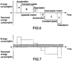
- Block A corresponds to the electricity consumed during acceleration of the lift car 107 to a predetermined speed in a direction of motion upwards along the mast 5.
- Block B corresponds to the power consumption when the lift car 107 increases its potential energy through moving at a constant speed upwards along the mast.
- Block C corresponds to the energy consumption during retardation and stop of the lift car 107.
- Block D represents the inverse power or the return of potential energy for storage during acceleration downwards of the lift car 107.
- Block E represents inverse energy consumption during motion at constant speed downwards and block F represents the inverse energy during retardation and stop of the lift car 1, 2 during downwards motion.
- Figure 7 shows graphically the power consumption that can be achieved according to the principles of the present invention whereby the power consumption is illustrated as constant with time in the hatched block and is obtained through stored potential energy from regenerative motor operation being recycled as power that is superimposed on the power that is consumed in Figure 6 .
- the graph is intended to give an example of how residual power that is recycled and stored in the energy storage system 10 that has been obtained during braking of the lift car 107 during its motion downwards and that is stored as transferred potential energy in, for example, the energy storage system 10, can be returned at times during the transport cycle of the lift when the power that is required is at its greatest, for example, at the instant of starting when the lift car 107 is accelerated.
- the collected energy in the power supply system can be regarded as constant, as is stated by the general laws of thermodynamics, whereby the only energy that is consumed in a lift is the energy that is lost due to the appearance of mechanical and electrical losses.
- the present invention has the major advantage that the levels of potential energy of the lift car 107 can be balanced during the acceleration phase and motion upwards along the mast 110 by the potential energy that is recycled through regenerative operation and braking of the lift car during its motion downwards along the mast and stored in an energy storage system that is supported by the lift car being returned to the electric motor 109 of the lift car to be used as driving power.
- the said recirculation i.e. the recycling of potential energy and the supply of recycled potential energy that has been stored in the energy store 60 to the electric motor 109 thus takes place in immediately in association with the lift car.
Landscapes
- Engineering & Computer Science (AREA)
- Structural Engineering (AREA)
- Civil Engineering (AREA)
- Automation & Control Theory (AREA)
- Mechanical Engineering (AREA)
- Transportation (AREA)
- Elevator Control (AREA)
- Electric Propulsion And Braking For Vehicles (AREA)
- Charge And Discharge Circuits For Batteries Or The Like (AREA)
Description
- The present invention concerns a method for the power supply for rack and pinion lifts according to the introduction to
claim 1. The invention concerns also an arrangement for the power supply for rack and pinion lifts according toclaim 7. - The power that is required to drive transport means, such as lifts, for persons or goods between floors in buildings varies, depending on a number of factors such as, for example, the instantaneous load on the lift, its speed, the direction of travel and in which part of the transport cycle the lift is currently operating. It is important that the power requirement be reduced as far as possible not only to reduce the installation and operating costs of the lift, but also to reduce the dimensions and space required for the power supply system of the lift. A rack and pinion lift comprises in general a load carrier such as a lift car that can be driven along a track by means of electric motors and cogged wheels, which track is normally in the form of a mast provided with a cogged rod. The electric motors that are selected are normally of three-phase type with a rated voltage of 380-500 V and a frequency of 50 or 60 Hz. The motors offer soft starting and stopping of the lift car at the selected landing by the use of frequency control. In a rack and pinion lift, not only the electric motor for driving the lift but also a control and monitoring unit for the control of the lift are supported immediately by the lift car.
- Rack and pinion lifts differ in a number of ways from conventional lifts such as cable-borne lifts and hydraulic lifts. One difference is, for example, that the lift car supports its own drive unit as it does also an associated control and monitoring unit for the control of the electric motor. The drive machinery is normally separated from the lift car in conventional lifts, for example arranged in a machine room and connected with the lift car in a manner that transfers motion through a cable or similar that runs from the machine room. Furthermore, rack and pinion lifts normally lack a counterweight and thus they lack the possibility of balancing the deadweight of the lift car, and this makes the start and acceleration phase critical, and requiring particularly high amounts of energy. Furthermore, as a consequence of the lift car supporting its own drive unit, the distance between a power supply unit at a ground level and the drive machinery of the lift car will vary, as the lift car moves upwards along the mast. This places particular demands on this type of lift. Rack and pinion lifts are thereby supplied by means of an electrical power line that leads from ground level up to the electric motor that is supported by the lift car. The electrical power line consists of electrical conductors surrounded by insulating material. The electrical power line is arranged, with the aid of a cable trolley or similar guided along the mast, to follow with an adapted length the lift car upwards and downwards along the mast, suspended under the lift car. It should be understood that, as the lift car carries its own drive unit, the electrical power line must be extended and shortened as the lift car moves along the mast. It can also be mentioned in addition to this that the length of the mast that is used in the currently used type of rack and pinion lift is formed from a number of sections that can be stacked and mounted on each other, in order to be able to vary the length of the mast. A consequence of this is, of course, that also the electrical power line is given a length that is adapted such that it can accompany the lift car along the complete height of the mast. It can finally be mentioned in this context that rack and pinion lifts are normally intended to be used for non-permanent use within the building industry, i.e. the lift is demounted when the building construction has been completed.
- Lifts are, on the other hand, becoming evermore higher and it has proved to be the case that the weight of the electrical power line, for lift heights up to 500 m and higher, becomes so great that it influences the loading capacity of the lift. The extension of the electrical power line as the lift car moves along the mast creates also difficulties with housing the complete cable length, in particular, when the power cable is to supply powerful motors with the current they require. In the case in which lifts that are to move between floors in very high buildings, the length, stiffness and deadweight of the electrical power line constitute problems, whereby the relatively heavy-duty electrical power line that accompanies the lift car becomes difficult to control, heavy to carry and house.
- It should be understood that the limited possibilities of the rack and pinion lifts to balance the potential energy of the lift car through its lack of a counterweight leads to a requirement for very powerful electric motors and associated electrical equipment such as electrical power lines with relatively large cross-sectional areas in order to be able to deliver the current required by the drive motors of the lift, in particular with respect to the instant of starting or the acceleration phase. When the lift car is driven to a certain level up the mast, its potential energy increases according to the equation: (Epot=mgh; where m = mass, h = height and g = acceleration due to gravity). In the absence of a counterweight, the potential energy of a lift car that has been lifted to a certain height has increased considerably, whereby the lift has been supplied with considerable amounts of energy through the power supply system. It should be realised that the energy that has been supplied is collected at the lift car as potential energy, when the lift car is in its elevated position.
- In addition to the said high elevations of the lift, it is, of course, also a problem that the lift motors drive the lift at full power only during certain periods, while the power supply system of the lift must be dimensioned based on the highest most critical power that is normally required only during short periods of the operation, in particular during the instant of starting and also during motion of the lift upwards along the mast. The greatest instantaneous force is, however, required at the instant of starting, i.e. during the initial part of the transport cycle when the lift car is accelerated. The power requirement falls considerably when the lift car has reached a constant speed. Changes in potential energy of the lift car of a conventional lift provided with a counterweight are balanced during motion by means of a counterweight. Rack and pinion lifts normally lack this possibility and the potential energy must be continuously overcome by the power supply system, which, of course, places considerable demands on this system. Enormous amounts of energy are generated when a rack and pinion lift car moves downwards along the mast during braking (retardation). The potential energy that is in this way released by the lift car is normally converted to heat energy in separate resistances (braking resistances) or it is fed back into the mains power network by a process known as "regenerative braking". It should be realised that a rack and pinion lift produces a considerably greater amount of energy during its motion downwards than conventional lifts provided with counterweights produce, due to the absence of a counterweight. Previous attempts to equip rack and pinion lifts with counterweights have been less than successful, mainly as a result of complicated designs and the extra work that the counterweight arrangement introduces during the tasks of mounting and demounting the lift.
- Since the power supply system and the associated electrical plant must be dimensioned to cope with the highest output power that is required during short periods, while the appearance of the standard load places considerably lower requirements for the capacity of the power plant, overload protection, the conductor system and other equipment in the consumer circuit will not be used fully with respect to the capacity of the equipment. As a part of this, the investment costs for the power supply system will be significantly higher and more extensive than necessary and they will be inefficient from the point of view of costs.
- While rack and pinion lifts are often used during the construction of buildings at locations that lack electrical power and the infrastructure of power stations, whereby alternative sources of energy are used as main power generator such as, for example, diesel-powered units, it should be understood that it would be desirable from a number of aspects to be able to reduce not only the size but also the cost of the external power-generating equipment and generator system that are required.
-
US 2007/084672 A1 describes a power supply system for a rack and pinion rack. -
US2010/0187045A1 discloses an electric power supplying system for a self-drive type elevator. -
Figure 1 shows how a generalmains power network 101 that is part of amain power generator 100 feeds a three-phase alternating current to atransformer 102 in order for it to be transformed down to a suitable level of voltage. AnAC bus 105 and a three-phaseelectrical power line 106 supplies a three-phaseelectric motor 109 supported by alift car 107 with electrical energy. AsFigure 1a makes most clear, thelift car 107 is a rack and pinion car and it can be driven along amast 110 through the interaction between acogged wheel 111 driven by theelectric motor 109 and acogged rod 112 arranged on the mast. The selected speed during raising and lowering of thelift car 107 is controlled through appropriate frequency conversion of theelectric motor 109. When thelift car 107 moves downwards along themast 110 during braking, an inverted or inverse flow of AC alternating current is generated in theelectric motor 109. The inverse flow of AC alternating current can, through what is known as "generative braking", be led back to the mains power network 101 (not shown in the drawings). -
Figure 2 shows an example in which themain power generator 100 is part of a diesel-poweredunit 113 intended to be used as a source of power. The diesel-poweredunit 113 is mechanically coupled to anAC power generator 114. Thepower generator 114 supplies AC alternating current that supplies theelectric motor 109 of thelift car 107 through anAC bus 105 and a three-phase electrical power line 106 (seeFigure 1 ). The system from this point onwards is the same as that described inFigure 1 . When thelift car 107 moves downwards along the mast, an inverted or inverse flow of AC alternating current is generated in the electric motor. The flow of inverse AC alternating current can be caused through generative braking to be dissipated as heat in a braking resistance, or it can be led back to the mains power network 101 (not shown in the drawings). - A first aim of the present invention is to achieve, based on the prior art technology, a method for the power supply of rack and pinion lifts that makes it possible to reduce the need for external power and in this way to reduce the cost of the power supply system of the lift as a whole. A second aim is to achieve a method for the power supply that solves the problems with the three-phase electrical power line that extends from the unit at ground level to the lift car. A third aim of the invention is to achieve an arrangement for the execution of the said method.
- These aims of the invention are achieved through a method that demonstrates the distinctive features and characteristics that are specified in
claim 1, and an arrangement that demonstrates the distinctive features and characteristics that are specified inclaim 7. - An embodiment of the invention will be described in more detail below with reference to the attached drawings, of which:
-
Figure 1 shows schematically a block diagram of a prior art power supply system, connected to the mains power network, for a rack and pinion lift that can be driven along a mast, -
Figure 1a shows a view from the front and in greater detail of the power supply that is a component of a rack and pinion lift of the type shown inFigure 1 , -
Figure 2 shows schematically a block diagram of the power supply system according toFigure 1 but now in a design with a generator unit powered by a diesel engine, known as a "generator system", -
Figure 3 shows schematically a block diagram of an arrangement according to the invention that has, for the power supply to a rack and pinion lift, an energy storage system that includes a supercondensor, and which system is connected to an AC alternating voltage supplied by the mains power network, -
Figure 3a shows schematically and in more detail a block diagram of the supercondensor shown inFigure 3 and its associated electrical circuits, -
Figure 3b shows schematically in a cross-sectional view a charging arrangement in an alternative design and that is part of the invention, including a current withdrawal trolley with current withdrawers, and with which arrangement a power receiver arranged at the lift car can be in continuous electrical connection with the principal power network, -
Figure 4 shows schematically a block diagram of an arrangement for the power supply of a rack and pinion lift according toFigure 3 , but in a design with an energy storage system that includes a flywheel, -
Figure 5 shows schematically a block diagram of an arrangement according toFigure 3 , but with an energy storage system that includes a battery pack, -
Figure 5a shows schematically a block diagram in more detail of the battery pack and its associated electrical circuits shown inFigure 5 , -
Figure 6 shows schematically in the form of a graph the energy requirement of a prior art rack and pinion lift at various stages A-F of a transport cycle, and -
Figure 7 shows schematically in the form of a graph corresponding toFigure 6 the energy requirement during the use of an arrangement for power supply according to the present invention. - With reference to
Figures 3-5 , a lift system with a rack and pinion lift for the transport of passengers or goods is shown. The lift comprises a load carrier in the form of alift car 107 that can be driven by means of a drive unit, comprising anelectric motor 109 and a transmission that has a rotatable shaft that interacts with acogged wheel 111, along a track in the form of a mast equipped with a cogged rod 112 (seeFigure 1a ). The saidelectric motor 109 is of three-phase type, having, for example, a rated voltage of 380-500 V and a frequency of 50 or 60 Hz. The present arrangement for power supply is shown inFigures 3-5 incorporated as a part of the two prior art designs that are shown inFigures 1 and 2 , to which reference is also made. - An energy storage system is part of the present power supply arrangement generally denoted by
reference number 10 and supported by thelift car 107, which energy storage system is designed to receive energy, store energy, and to supply the stored energy to theelectric motor 109 of thelift car 107 through a first bus, aDC bus 11. TheDC bus 11 has apositive side 13 and anegative side 14. Aprincipal power network 100 that produces power supplies three-phase AC alternating voltage. The saidprincipal power network 100 may be constituted by a mains power network, or by a generator system that comprises a diesel-powered unit with its associated power generator of the types shown inFigures 1 and 2 . Theenergy storage system 10 that is supported by thelift car 107 is designed to store energy of the type that is produced during regenerative operation of theelectric motor 109 of the lift car, i.e. the energy that is released when thelift car 107 is retarded during its movement downwards along themast 110. Furthermore, theenergy storage system 10 is designed for the storage of energy that has been collected directly from theprincipal power network 100, either when thelift car 107 is located at a ground level or when it is located at a predetermined location along the pathway of thelift car 107 along themast 110. A second bus, anAC bus 20, extends from a ground level and it includes a three-phase electrical power line from theprincipal power network 100 and onwards vertically upwards along themast 110. The three-phase electrical power line that functions as an AC bus is so attached and supported at themast 110 that it can be considered as stationary relative to thelift car 107 that can be driven upwards and downwards along the mast. The expressions "AC bus", "DC bus" and "bus" are used below generally to denote a system of lines, current rails or similar current-transfer arrangements that bind several electrical units together. - The
reference number 24 generally denotes a power transfer means that allows electrical energy to be transferred between theprincipal power network 100 and theenergy storage system 10 that is supported by thelift car 107. It will be made clear below that the power transfer means 24 may be designed in a number of different ways. The power transfer means 24 is divided in the following into a number (n) charging stations 24:1-24:n located at suitable distances from each other along themast 110. A chargingarrangement 25 is present in each charging station that is in electrical connection with theprincipal power network 100 through abranch cable 26 and the saidAC bus 20. The chargingarrangement 25 comprises apower deliverer 30 supported by themast 110 and designed to interact with apower receiver 31 arranged at thelift car 107 in order to allow electrical energy to, by means ofcontacts 32 that are part of the chargingarrangement 25, be transferred as is shown by thearrows 17 from theprincipal power network 100 to theenergy storage system 10 when thelift car 107 is located in such a position along its track along the mast that thecontacts 32 are in current-transferring contact with each other. In order to function as charger, the chargingarrangement 25 comprises a directcurrent converter 35 supported by thelift car 107 to convert the AC alternating current of the principal power network to a DC direct current, which can be transferred to theenergy store 10 as a charging current. As the drawings make clear, the interactingcontacts 32 are supported by themast 110 and by thelift car 107, respectively. -
Figure 3b shows thepower deliverer 30 andpower receiver 31 of the power transfer means 24 in an alternative design, shown in a cross-section through the mast. The charging stations 24:1-24:n described above and the AC bus has been replaced in the design shown by arail bar 50 with electrically conducting current rails that extend along themast 110. Current supply takes place in this way by means of acurrent withdrawal trolley 51 with its associated current withdrawers that accompanies thelift car 107 and runs on insulating guides along therail bar 50. Thecurrent withdrawal trolley 51 runs along and is supported by bearings throughwheels 52 along aguide rail 53 in the form of a T-beam attached along the mast. There are here four current withdrawers, of which 55a, 55b, 55c constitute three-phase supply and 55d the earth connector. This design has the advantage that thepower receiver 31 of thelift car 107 can be placed in electrical connection with theprincipal power network 100 through thecontacts 32 at any freely chosen place along the track, i.e. charging can take place anywhere along the mast independently of the level at which the lift car is located. It is appropriate that connection and disconnection take place by means of aswitch 55 of three-phase contact type, arranged at the location and in the manner that is suggested by the dash-dot line inFigure 4 . - When the
lift car 107 moves upwards along themast 110 under the influence of the power supply and the AC alternating currentelectric motor 109 supported by thelift car 107, the electric motor is driven principally by energy that is stored in theenergy storage system 10. Thus, the lift car increases its potential energy during the motion of thelift car 107 upwards along the mast through energy that is obtained from theenergy storage system 10. In the case in which the energy stored in theenergy storage system 10 is insufficient to drive thelift car 107 up to a predetermined level of themast 110, further or supplementary energy can be retrieved from theprincipal power network 100. According to the invention, energy is retrieved from theprincipal power network 100 by thelift car 107 being temporarily stopped in association with any one of the charging stations 24:1-24:n arranged along themast 110, whereby theenergy store 10 is filled, with thecontacts 32 being in a mutual current-transfer position. Alternatively, charging can take place at an arbitrary position along themast 110 through the use of the technology described above that includes the supply of power by means of thecurrent withdrawal trolley 51 and its associatedcurrent withdrawers 55a-55d. It should be understood that the time that is required to fill theenergy storage system 10, i.e. the stop time or the charging time, may vary, depending of the energy storage technology chosen. This will, however, be described in more detail below. - During the motion of the
lift car 107 downwards along themast 110, what is known as "regenerative braking" of theelectric motor 109 is used, whereby the energy generated during braking is collected and stored in theenergy storage system 10 that is supported by the lift car. This means that the collected potential energy that is gradually released during the braking motion of thelift car 107 down themast 110 is collected and led to theenergy storage system 10. The collected energy can later be used for the driving of theelectric motor 109 of the lift car during its movement upwards along themast 110. In particular, the stored energy of thelift car 107 constitutes a significant addition during the acceleration phase of the lift car, which means that the requirement for external power supplied from the mains power network can be reduced in comparison with prior art technology, and thus also the capacity requirement placed on the external power supply system of the lift. - The power to and from the relevant units that are connected to the
DC bus 11 are controlled and monitored by means of acontrol system 40, for example a programmable logic controller (PLC), or computer supported by thelift car 107. For monitoring and surveillance of the voltage levels of theenergy store 10, what is known as a buck-boost circuit or a similar circuit for voltage monitoring can be used, arranged at a suitable location along the DC bus 11 (not shown in the drawings). - As has been stated above, the
energy storage system 10 may be designed in a number of different ways whereby the time required for charging of the store is not the least of the factors that are influenced to a great degree by the selected energy storage technology, With reference to alsoFigures 3a and5a , a number of energy storage systems of differing designs will be described in more detail below. -
Figure 3 shows in a first embodiment of an arrangement according to the invention whereby anenergy storage system 10 that includes anenergy store 60 with asupercondensor 27 is used for the power supply to a rack andpinion lift car 107. Thelift car 107 is braked regeneratively during its motion downwards along themast 110 whereby the potential energy retrieved during the braking is led to thesupercondensor 27 that is a component of theenergy store 60 for storage. A DC/AC converter 12 is connected through theDC bus 11 to the ACelectric motor 109 of the lift car for conversion of the DC direct current that is delivered by thesupercondensor 27 into an AC alternating current adapted for driving theelectric motor 109. -
Figure 3 shows schematically in a block diagram how thesupercondensor 27 that is a component of the energy store functions. To be precise, adiode 27a and a chargingswitch 27b are arranged in a first branch whereby the branch is connected in parallel across thepositive side 13 and thenegative side 14 of theDC bus 11. Further, a second branch is present with aswitch 27c that, when closed, causes thesupercondensor 27 to be discharged. Thediode 27a allows current to pass only in a direction that leads to charging of thesupercondensor 27, whereby discharge cannot take place through the said first branch, which contains thediode 27a. When the first branch is closed, the voltage of thesupercondensor 27 increases such that it eventually exceeds the voltage across acondensor 27d that is part of theDC bus 11. Since the voltage across thesupercondensor 27 is higher than the voltage across thecondensor 27d of theDC bus 11, the supercondensor can be connected for the delivery of stored energy in the form of current to theelectric motor 109 of thelift car 107 through theconverter 12, which takes place in practice through the second branch being closed by means of theswitch 27c. -
Figure 4 shows a second embodiment of an arrangement according to the invention whereby anenergy storage system 10 that includes anenergy store 60 with aflywheel 23 is used for the power supply to a rack andpinion lift car 107. Thelift car 107 is braked regeneratively during its motion downwards along themast 110 whereby the potential energy retrieved during the braking is led to theflywheel 23 for storage. A DC/AC converter 12 is connected to theAC drive motor 109 of thelift car 107 through aDC bus 11 with apositive side 13 and anegative side 14. Theenergy storage system 10 comprises a DC/AC converter 21, a three-phaseAC induction motor 22 and the saidflywheel 23. Theinduction motor 22 may be constituted by, for example, a traction motor, i.e. a three-phase synchronous motor with permanent magnets. When thelift car 107 moves downwards through the influence of the associatedelectric motor 109, energy is stored in theflywheel 23, and this takes place as a consequence of theelectric motor 109 that is supported by thelift car 107 being reversed and functioning in this case as a generator. Thus the AC alternating current that is generated from thelift motor 109 is converted to DC direct current by theconverter 20, which direct current is led after passage through theDC bus 11 to theenergy storage system 10. The said energy storage system receives and stores the potential energy as kinetic energy in theflywheel 23 through this flywheel being accelerated by means of themotor 22. The kinetic energy in the flywheel can, when power is needed, be converted to electrical energy, which can be used by thedrive motor 109 of thelift 107. -
Figure 5 shows a third embodiment of an arrangement according to the invention whereby anenergy storage system 10 that includes anenergy store 60 with abattery pack 70 is used for the power supply to a rack andpinion lift car 107. Thelift car 107 is braked regeneratively during its motion downwards along themast 110 whereby the potential energy retrieved during the braking is led to the battery pack for storage. A DC/AC converter is connected to theAC drive motor 109 of thelift car 107 through aDC bus 11 with apositive side 13 and anegative side 14. -
Figure 5a shows schematically in a block diagram how theenergy store 60 with thebattery pack 70 functions. To be more precise, theenergy storage system 10 comprises in this case a battery pack that is controlled by means of aswitch 71, for the storage of energy and the supply of the said energy in the form of a DC direct current. - It should be realised that it may be suitable in certain cases of lift applications of the type described above to combine the alternative energy storage technologies described above. It would be conceivable, for example, to combine any one of the relatively large and permanent storage capacities of the
supercondensor 27 or thebattery pack 70 with the rapid and efficient energy management of theflywheel 23. - With reference to
Figure 6 , there is shown schematically in the form of a graph the energy requirement for a rack and pinion lift at various stages A-F of a transport cycle whereby block A corresponds to the electricity consumed during acceleration of thelift car 107 to a predetermined speed in a direction of motion upwards along the mast 5. Block B corresponds to the power consumption when thelift car 107 increases its potential energy through moving at a constant speed upwards along the mast. Block C corresponds to the energy consumption during retardation and stop of thelift car 107. Block D represents the inverse power or the return of potential energy for storage during acceleration downwards of thelift car 107. Block E represents inverse energy consumption during motion at constant speed downwards and block F represents the inverse energy during retardation and stop of thelift car -
Figure 7 shows graphically the power consumption that can be achieved according to the principles of the present invention whereby the power consumption is illustrated as constant with time in the hatched block and is obtained through stored potential energy from regenerative motor operation being recycled as power that is superimposed on the power that is consumed inFigure 6 . The graph is intended to give an example of how residual power that is recycled and stored in theenergy storage system 10 that has been obtained during braking of thelift car 107 during its motion downwards and that is stored as transferred potential energy in, for example, theenergy storage system 10, can be returned at times during the transport cycle of the lift when the power that is required is at its greatest, for example, at the instant of starting when thelift car 107 is accelerated. It should be furthermore understood that the collected energy in the power supply system can be regarded as constant, as is stated by the general laws of thermodynamics, whereby the only energy that is consumed in a lift is the energy that is lost due to the appearance of mechanical and electrical losses. - As has been mentioned above, the present invention has the major advantage that the levels of potential energy of the
lift car 107 can be balanced during the acceleration phase and motion upwards along themast 110 by the potential energy that is recycled through regenerative operation and braking of the lift car during its motion downwards along the mast and stored in an energy storage system that is supported by the lift car being returned to theelectric motor 109 of the lift car to be used as driving power. The said recirculation, i.e. the recycling of potential energy and the supply of recycled potential energy that has been stored in theenergy store 60 to theelectric motor 109 thus takes place in immediately in association with the lift car. - This distinctive feature of the invention is interesting since it means that the principal power network that produces power needs only to supply a limited part of the current that is required during the critical acceleration phase of the lift car (see also
Figures 6-7 ). - The invention is not limited to that which has been described above and shown in the drawings: it can be changed and modified in several different ways within the scope of the innovative concept defined by the attached patent claims.
Claims (8)
- A method to achieve a power supply system for a lift of the type in which drive machinery (109) is supported by a load carrier (107) and can drive the load carrier in a first and a second direction along a track in an essentially vertical mast (110) by means of the interaction between a cogged wheel (111) and cogged rod (112), comprising the steps:a) that a load carrier (107) is arranged,b) that the load carrier (107) is arranged to support an electrically operated electric motor (109) that is a component of the drive machinery, which electric motor is selected such that it generates a flow of energy during regenerative operation,c) that the electric motor (109) is arranged such that it can drive the load carrier (107) in the first direction along the track and can drive the load carrier during regenerative operation to generate a flow of energy during braking and motion in the second direction along the track,characterised in the following steps;d) that the load carrier (107) is arranged to support an energy storage system (10) that includes an energy store (60) designed to store, receive and release electrical energy,e) that the load carrier (107) is provided with a first current-transfer bus (11) that allows the energy flow that is emitted from the electric motor (109) during braking and regenerative operation to be transferred from the electric motor to the energy store (60) that is part of the energy storage system (10) and, when necessary, to be inversely transferred from the energy store to the drive motor, andf) that the load carrier (107) increases its potential energy during acceleration or motion in the first direction along the mast (110) through the influence of electrical energy that has been obtained from the energy store (60),g) that the load carrier (107) is equipped with a control and monitoring system (40) that is supported by the load carrier and monitors and controls the flow of current between the drive machinery (109) of the load carrier and the energy store (60),h) that a principal power network (100) is arranged at a ground level,i) that a second current-transfer bus (20) is arranged extending from the principal power network (100) at ground level and onwards upwards along the mast (110),j) that the second bus (20) is arranged to be stationary relative to the load carrier (107) that can be driven along the mast (110),k) that power transfer means (24) that include a power deliverer (30) and a power receiver (31) that interacts with it are arranged,I) that the power deliverer (30) is arranged supported by the mast (110) and that the power receiver (31) is arranged supported by the load carrier (107) and that electrical energy can be transferred from the principal power network (100) to the energy store (60) with the power deliverer and the power receiver placed into their interacting position along the track of the load carrier (107) along the mast (110),m)that the load carrier (107) is supplied with electrical energy from the principal power network (100) through the energy store (60) being, when necessary, charged with electrical energy from the principal power network (100) transferred through the power transfer means (24),andn) the first bus is arranged as a DC bus for the conduction of direct current, and the second bus is arranged as an AC bus for the conduction of three-phase alternating current.
- The method according to claim 1, whereby the control and monitoring system (40) is selected among any one of the following: a programmable logic controller (PLC) and a computer.
- The method according to any one of claims 1-2, whereby the power transfer means (24) is selected such that it includes any one of the following: a number (n) of charging stations (24:1-24:n) located at separations from each other along the mast (110) where each charging station includes a power deliverer (30) intended to interact with a power receiver (31) supported by the load carrier (107), a rail bar (50) with electrically conducting current rails that extend along the mast (110) and where current feed occurs by means of a current withdrawal trolley (51) and its associated current withdrawal units (55a, 55b, 55c, 55d) that runs along the rail bar guided by the mast and accompanying the lift car (107), and that connection and disconnection takes place by means of a switch (55).
- The method according to any of claims 1-3, whereby the energy store (60) is charged with energy from the principal power network (100) when the load carrier (107) is located at ground level.
- The method according to any of claims 1-4, whereby the second bus (20) is arranged stationary relative to the load carrier (107) supported directly on the mast (110) or on a building located in nearby.
- The method according to any one of claims 1-5, whereby the energy store (60) that is a part of the energy storage system (10) is selected among any one of the following: a supercondensor (27), a battery pack (70), a flywheel (23), and a combination of these.
- An arrangement for the power supply for a lift of the type in which drive machinery (109) is supported by a load carrier (107) and can drive the load carrier in a first and a second direction along a track in an essentially vertical mast (110) by means of the interaction between a cogged wheel (111) and cogged rod (112), each load carrier (107) of the lift comprises:a) an electrically operated electric motor (109) that is part of the drive machinery and is arranged to drive the load carrier (107) upwards along the track and to generate a flow of energy through regenerative operation during inverse operation and braking of the load carrier during motion in the said second direction downwards along the track,characterised in that the arrangement comprises;b) an energy storage system (10) with an energy store (60) for the storage, reception and delivery of electrical energy to the electric motor (109),c) a first current-transfer bus (11) that allows the energy flow that is emitted from the electric motor (109) during braking to be transferred from the electric motor to the energy store (60) that is part of the energy storage system (10) and, when necessary, to be inversely transferred from the energy store to the drive motor, andd) a control and monitoring system (40) for the monitoring and control of the flow of current between the drive machinery (109) of the load carrier and the energy store (60), the arrangement further comprising,e) a principal power network (100) arranged at a ground level,f) a second current-transfer bus (20) that extends from the principal power network (100) and onwards upwards along the mast (110) and that is stationary relative to the load carrier (107) that can be driven along the mast (110),g) a power transfer means (24) that includes a power deliverer (30) arranged at the mast (110) designed to interact with a power receiver (31) arranged at the load carrier, and were electrical energy is transferred from the principal power network (100) to the energy store (60) of the energy storage system (10) when the said power deliverer and power receiver are located in their interacting positions, whereinh) the first bus is arranged as a DC bus for the conduction of direct current, and the second bus is arranged as an AC bus for the conduction of three-phase alternating current.
- The use of a supercondensor (27), a battery pack (70), a flywheel (23) or a combination of these for the storage of energy at a lift with a load carrier (107) of the type that is specified in any one of the preceding claims.
Applications Claiming Priority (1)
| Application Number | Priority Date | Filing Date | Title |
|---|---|---|---|
| PCT/SE2011/050359 WO2012134363A1 (en) | 2011-03-29 | 2011-03-29 | Method and device for the power supply for rack and pinion lifts |
Publications (3)
| Publication Number | Publication Date |
|---|---|
| EP2691333A1 EP2691333A1 (en) | 2014-02-05 |
| EP2691333A4 EP2691333A4 (en) | 2014-11-19 |
| EP2691333B1 true EP2691333B1 (en) | 2018-12-12 |
Family
ID=46931730
Family Applications (1)
| Application Number | Title | Priority Date | Filing Date |
|---|---|---|---|
| EP11862820.5A Active EP2691333B1 (en) | 2011-03-29 | 2011-03-29 | Method and device for the power supply for rack and pinion lifts |
Country Status (4)
| Country | Link |
|---|---|
| EP (1) | EP2691333B1 (en) |
| CN (1) | CN103492303B (en) |
| ES (1) | ES2724748T3 (en) |
| WO (1) | WO2012134363A1 (en) |
Families Citing this family (9)
| Publication number | Priority date | Publication date | Assignee | Title |
|---|---|---|---|---|
| GB2542488B (en) * | 2012-12-14 | 2019-11-13 | Stannah Stairlifts Ltd | Improvements in or relating to stairlifts |
| CN106573758B (en) * | 2014-08-18 | 2019-11-15 | 奥的斯电梯公司 | Embedded energy storage for driving vehicles and auxiliary systems |
| AU2016231585B2 (en) * | 2015-09-25 | 2018-08-09 | Otis Elevator Company | Elevator component separation assurance system and method of operation |
| EP3223420B1 (en) * | 2016-03-22 | 2020-05-06 | Siemens Aktiengesellschaft | Power converter arrangement for secure braking of a drive system |
| EP3407459A1 (en) * | 2017-05-25 | 2018-11-28 | Siemens Aktiengesellschaft | Power supply system and method |
| GB201719483D0 (en) * | 2017-11-23 | 2018-01-10 | Deciwatt Ltd | Portable apparatus for generating electricity |
| CN108657913B (en) * | 2018-07-19 | 2023-08-15 | 长春工业大学 | A small cargo carrier |
| GB201817623D0 (en) * | 2018-10-29 | 2018-12-12 | Stiltz Ltd | An elevator safety system |
| US20240079974A1 (en) * | 2022-09-02 | 2024-03-07 | Otis Elevator Company | Multiple drive system for regenerative energy management in an elevator installation |
Family Cites Families (6)
| Publication number | Priority date | Publication date | Assignee | Title |
|---|---|---|---|---|
| JPH1192059A (en) * | 1997-09-19 | 1999-04-06 | Ohbayashi Corp | Lift for construction |
| JP4347982B2 (en) * | 2000-02-28 | 2009-10-21 | 三菱電機株式会社 | Elevator control device |
| JP2003238051A (en) * | 2002-02-15 | 2003-08-27 | Sansei Kenki Kk | Elevator for construction work |
| CN101146729B (en) * | 2005-04-01 | 2011-02-02 | 三菱电机株式会社 | Elevator power supply system |
| DE102005049408A1 (en) * | 2005-10-13 | 2007-04-26 | Wittenstein Ag | Self-propelled elevator |
| EP2106380B1 (en) * | 2007-01-11 | 2011-12-28 | Otis Elevator Company | Thermoelectric thermal management system for the energy storage system in a regenerative elevator |
-
2011
- 2011-03-29 EP EP11862820.5A patent/EP2691333B1/en active Active
- 2011-03-29 WO PCT/SE2011/050359 patent/WO2012134363A1/en not_active Ceased
- 2011-03-29 ES ES11862820T patent/ES2724748T3/en active Active
- 2011-03-29 CN CN201180069700.0A patent/CN103492303B/en active Active
Non-Patent Citations (1)
| Title |
|---|
| None * |
Also Published As
| Publication number | Publication date |
|---|---|
| WO2012134363A1 (en) | 2012-10-04 |
| CN103492303B (en) | 2016-05-18 |
| EP2691333A1 (en) | 2014-02-05 |
| CN103492303A (en) | 2014-01-01 |
| EP2691333A4 (en) | 2014-11-19 |
| ES2724748T3 (en) | 2019-09-13 |
Similar Documents
| Publication | Publication Date | Title |
|---|---|---|
| WO2012134363A1 (en) | Method and device for the power supply for rack and pinion lifts | |
| FI120092B (en) | Elevator system and procedure for reducing the overall power of an elevator system | |
| WO2008136692A2 (en) | Multi-car cyclic magnetic elevator with gravity linear electric generator/motor | |
| CN101282898A (en) | Power supply system of elevator | |
| EP3318527A1 (en) | Electrically autonomous elevator system | |
| JP2010064864A (en) | Elevator system | |
| EP2539266B1 (en) | Power supply system for rack and pinion lifts and method for powering these | |
| CN107324163A (en) | Uninterrupted rescue operation | |
| EP3746389B1 (en) | Electric linear motor | |
| US12358758B2 (en) | Durable pneumatic elevator system and methods | |
| JP7786719B2 (en) | Elevator counterweight assembly for energy recovery and corresponding elevator system | |
| CN113800361A (en) | Elevator driving system based on electric chassis | |
| CN111327126A (en) | Multi-shaft charging | |
| CN203451005U (en) | Numerical-control magnetic-pull upright elevator | |
| CN213684411U (en) | Elevator energy recovery storage device | |
| CN103407868B (en) | Numerical control magnetic pull type vertical elevator | |
| SE536864C2 (en) | Method and apparatus for power supply of rack-mounted lifts. | |
| WO2010138113A1 (en) | Modular arrangement of a double wrap traction elevator machine with dynamic braking | |
| CN111099483B (en) | Elevator, electric energy storage and release controller, and electric energy storage and release method | |
| CN109484945A (en) | Elevator wire rope power generator | |
| CN204675735U (en) | A kind of elevator traction brake equipment | |
| CN203728339U (en) | Power supply device for charging lifting drive part of stopping device | |
| CN119660517A (en) | Continuous power generation gravity energy storage lifting system and operation method thereof | |
| EP3922589A1 (en) | Installation arrangement and construction-time elevator | |
| CN222080672U (en) | A power replacement device for rail locomotive |
Legal Events
| Date | Code | Title | Description |
|---|---|---|---|
| PUAI | Public reference made under article 153(3) epc to a published international application that has entered the european phase |
Free format text: ORIGINAL CODE: 0009012 |
|
| 17P | Request for examination filed |
Effective date: 20131025 |
|
| AK | Designated contracting states |
Kind code of ref document: A1 Designated state(s): AL AT BE BG CH CY CZ DE DK EE ES FI FR GB GR HR HU IE IS IT LI LT LU LV MC MK MT NL NO PL PT RO RS SE SI SK SM TR |
|
| DAX | Request for extension of the european patent (deleted) | ||
| A4 | Supplementary search report drawn up and despatched |
Effective date: 20141020 |
|
| RIC1 | Information provided on ipc code assigned before grant |
Ipc: B66B 9/02 20060101AFI20141014BHEP Ipc: B66B 1/30 20060101ALI20141014BHEP Ipc: B66B 9/16 20060101ALI20141014BHEP Ipc: B66B 11/00 20060101ALI20141014BHEP Ipc: B66B 11/04 20060101ALI20141014BHEP |
|
| GRAP | Despatch of communication of intention to grant a patent |
Free format text: ORIGINAL CODE: EPIDOSNIGR1 |
|
| STAA | Information on the status of an ep patent application or granted ep patent |
Free format text: STATUS: GRANT OF PATENT IS INTENDED |
|
| INTG | Intention to grant announced |
Effective date: 20180823 |
|
| RIN1 | Information on inventor provided before grant (corrected) |
Inventor name: ELIASSON, JONNY Inventor name: CEDERBLAD, LARS |
|
| GRAS | Grant fee paid |
Free format text: ORIGINAL CODE: EPIDOSNIGR3 |
|
| GRAA | (expected) grant |
Free format text: ORIGINAL CODE: 0009210 |
|
| STAA | Information on the status of an ep patent application or granted ep patent |
Free format text: STATUS: THE PATENT HAS BEEN GRANTED |
|
| AK | Designated contracting states |
Kind code of ref document: B1 Designated state(s): AL AT BE BG CH CY CZ DE DK EE ES FI FR GB GR HR HU IE IS IT LI LT LU LV MC MK MT NL NO PL PT RO RS SE SI SK SM TR |
|
| REG | Reference to a national code |
Ref country code: GB Ref legal event code: FG4D |
|
| REG | Reference to a national code |
Ref country code: CH Ref legal event code: EP |
|
| REG | Reference to a national code |
Ref country code: AT Ref legal event code: REF Ref document number: 1075719 Country of ref document: AT Kind code of ref document: T Effective date: 20181215 |
|
| REG | Reference to a national code |
Ref country code: DE Ref legal event code: R096 Ref document number: 602011054855 Country of ref document: DE |
|
| REG | Reference to a national code |
Ref country code: IE Ref legal event code: FG4D |
|
| REG | Reference to a national code |
Ref country code: NL Ref legal event code: MP Effective date: 20181212 |
|
| REG | Reference to a national code |
Ref country code: LT Ref legal event code: MG4D |
|
| PG25 | Lapsed in a contracting state [announced via postgrant information from national office to epo] |
Ref country code: LV Free format text: LAPSE BECAUSE OF FAILURE TO SUBMIT A TRANSLATION OF THE DESCRIPTION OR TO PAY THE FEE WITHIN THE PRESCRIBED TIME-LIMIT Effective date: 20181212 Ref country code: HR Free format text: LAPSE BECAUSE OF FAILURE TO SUBMIT A TRANSLATION OF THE DESCRIPTION OR TO PAY THE FEE WITHIN THE PRESCRIBED TIME-LIMIT Effective date: 20181212 Ref country code: NO Free format text: LAPSE BECAUSE OF FAILURE TO SUBMIT A TRANSLATION OF THE DESCRIPTION OR TO PAY THE FEE WITHIN THE PRESCRIBED TIME-LIMIT Effective date: 20190312 Ref country code: BG Free format text: LAPSE BECAUSE OF FAILURE TO SUBMIT A TRANSLATION OF THE DESCRIPTION OR TO PAY THE FEE WITHIN THE PRESCRIBED TIME-LIMIT Effective date: 20190312 Ref country code: LT Free format text: LAPSE BECAUSE OF FAILURE TO SUBMIT A TRANSLATION OF THE DESCRIPTION OR TO PAY THE FEE WITHIN THE PRESCRIBED TIME-LIMIT Effective date: 20181212 |
|
| REG | Reference to a national code |
Ref country code: AT Ref legal event code: MK05 Ref document number: 1075719 Country of ref document: AT Kind code of ref document: T Effective date: 20181212 |
|
| PG25 | Lapsed in a contracting state [announced via postgrant information from national office to epo] |
Ref country code: RS Free format text: LAPSE BECAUSE OF FAILURE TO SUBMIT A TRANSLATION OF THE DESCRIPTION OR TO PAY THE FEE WITHIN THE PRESCRIBED TIME-LIMIT Effective date: 20181212 Ref country code: GR Free format text: LAPSE BECAUSE OF FAILURE TO SUBMIT A TRANSLATION OF THE DESCRIPTION OR TO PAY THE FEE WITHIN THE PRESCRIBED TIME-LIMIT Effective date: 20190313 Ref country code: SE Free format text: LAPSE BECAUSE OF FAILURE TO SUBMIT A TRANSLATION OF THE DESCRIPTION OR TO PAY THE FEE WITHIN THE PRESCRIBED TIME-LIMIT Effective date: 20181212 Ref country code: AL Free format text: LAPSE BECAUSE OF FAILURE TO SUBMIT A TRANSLATION OF THE DESCRIPTION OR TO PAY THE FEE WITHIN THE PRESCRIBED TIME-LIMIT Effective date: 20181212 |
|
| PG25 | Lapsed in a contracting state [announced via postgrant information from national office to epo] |
Ref country code: NL Free format text: LAPSE BECAUSE OF FAILURE TO SUBMIT A TRANSLATION OF THE DESCRIPTION OR TO PAY THE FEE WITHIN THE PRESCRIBED TIME-LIMIT Effective date: 20181212 |
|
| PG25 | Lapsed in a contracting state [announced via postgrant information from national office to epo] |
Ref country code: PT Free format text: LAPSE BECAUSE OF FAILURE TO SUBMIT A TRANSLATION OF THE DESCRIPTION OR TO PAY THE FEE WITHIN THE PRESCRIBED TIME-LIMIT Effective date: 20190412 Ref country code: PL Free format text: LAPSE BECAUSE OF FAILURE TO SUBMIT A TRANSLATION OF THE DESCRIPTION OR TO PAY THE FEE WITHIN THE PRESCRIBED TIME-LIMIT Effective date: 20181212 Ref country code: IT Free format text: LAPSE BECAUSE OF FAILURE TO SUBMIT A TRANSLATION OF THE DESCRIPTION OR TO PAY THE FEE WITHIN THE PRESCRIBED TIME-LIMIT Effective date: 20181212 |
|
| PG25 | Lapsed in a contracting state [announced via postgrant information from national office to epo] |
Ref country code: RO Free format text: LAPSE BECAUSE OF FAILURE TO SUBMIT A TRANSLATION OF THE DESCRIPTION OR TO PAY THE FEE WITHIN THE PRESCRIBED TIME-LIMIT Effective date: 20181212 Ref country code: IS Free format text: LAPSE BECAUSE OF FAILURE TO SUBMIT A TRANSLATION OF THE DESCRIPTION OR TO PAY THE FEE WITHIN THE PRESCRIBED TIME-LIMIT Effective date: 20190412 Ref country code: SK Free format text: LAPSE BECAUSE OF FAILURE TO SUBMIT A TRANSLATION OF THE DESCRIPTION OR TO PAY THE FEE WITHIN THE PRESCRIBED TIME-LIMIT Effective date: 20181212 Ref country code: EE Free format text: LAPSE BECAUSE OF FAILURE TO SUBMIT A TRANSLATION OF THE DESCRIPTION OR TO PAY THE FEE WITHIN THE PRESCRIBED TIME-LIMIT Effective date: 20181212 Ref country code: SM Free format text: LAPSE BECAUSE OF FAILURE TO SUBMIT A TRANSLATION OF THE DESCRIPTION OR TO PAY THE FEE WITHIN THE PRESCRIBED TIME-LIMIT Effective date: 20181212 |
|
| REG | Reference to a national code |
Ref country code: ES Ref legal event code: FG2A Ref document number: 2724748 Country of ref document: ES Kind code of ref document: T3 Effective date: 20190913 Ref country code: DE Ref legal event code: R097 Ref document number: 602011054855 Country of ref document: DE |
|
| PLBE | No opposition filed within time limit |
Free format text: ORIGINAL CODE: 0009261 |
|
| STAA | Information on the status of an ep patent application or granted ep patent |
Free format text: STATUS: NO OPPOSITION FILED WITHIN TIME LIMIT |
|
| PG25 | Lapsed in a contracting state [announced via postgrant information from national office to epo] |
Ref country code: SI Free format text: LAPSE BECAUSE OF FAILURE TO SUBMIT A TRANSLATION OF THE DESCRIPTION OR TO PAY THE FEE WITHIN THE PRESCRIBED TIME-LIMIT Effective date: 20181212 Ref country code: MC Free format text: LAPSE BECAUSE OF FAILURE TO SUBMIT A TRANSLATION OF THE DESCRIPTION OR TO PAY THE FEE WITHIN THE PRESCRIBED TIME-LIMIT Effective date: 20181212 Ref country code: DK Free format text: LAPSE BECAUSE OF FAILURE TO SUBMIT A TRANSLATION OF THE DESCRIPTION OR TO PAY THE FEE WITHIN THE PRESCRIBED TIME-LIMIT Effective date: 20181212 Ref country code: AT Free format text: LAPSE BECAUSE OF FAILURE TO SUBMIT A TRANSLATION OF THE DESCRIPTION OR TO PAY THE FEE WITHIN THE PRESCRIBED TIME-LIMIT Effective date: 20181212 |
|
| PGFP | Annual fee paid to national office [announced via postgrant information from national office to epo] |
Ref country code: GB Payment date: 20190516 Year of fee payment: 9 |
|
| REG | Reference to a national code |
Ref country code: CH Ref legal event code: PL |
|
| 26N | No opposition filed |
Effective date: 20190913 |
|
| PG25 | Lapsed in a contracting state [announced via postgrant information from national office to epo] |
Ref country code: LU Free format text: LAPSE BECAUSE OF NON-PAYMENT OF DUE FEES Effective date: 20190329 |
|
| REG | Reference to a national code |
Ref country code: BE Ref legal event code: MM Effective date: 20190331 |
|
| PG25 | Lapsed in a contracting state [announced via postgrant information from national office to epo] |
Ref country code: IE Free format text: LAPSE BECAUSE OF NON-PAYMENT OF DUE FEES Effective date: 20190329 Ref country code: LI Free format text: LAPSE BECAUSE OF NON-PAYMENT OF DUE FEES Effective date: 20190331 Ref country code: CH Free format text: LAPSE BECAUSE OF NON-PAYMENT OF DUE FEES Effective date: 20190331 |
|
| PG25 | Lapsed in a contracting state [announced via postgrant information from national office to epo] |
Ref country code: FR Free format text: LAPSE BECAUSE OF NON-PAYMENT OF DUE FEES Effective date: 20190331 Ref country code: BE Free format text: LAPSE BECAUSE OF NON-PAYMENT OF DUE FEES Effective date: 20190331 |
|
| PG25 | Lapsed in a contracting state [announced via postgrant information from national office to epo] |
Ref country code: TR Free format text: LAPSE BECAUSE OF FAILURE TO SUBMIT A TRANSLATION OF THE DESCRIPTION OR TO PAY THE FEE WITHIN THE PRESCRIBED TIME-LIMIT Effective date: 20181212 |
|
| PG25 | Lapsed in a contracting state [announced via postgrant information from national office to epo] |
Ref country code: MT Free format text: LAPSE BECAUSE OF NON-PAYMENT OF DUE FEES Effective date: 20190329 |
|
| GBPC | Gb: european patent ceased through non-payment of renewal fee |
Effective date: 20200329 |
|
| PG25 | Lapsed in a contracting state [announced via postgrant information from national office to epo] |
Ref country code: GB Free format text: LAPSE BECAUSE OF NON-PAYMENT OF DUE FEES Effective date: 20200329 |
|
| PG25 | Lapsed in a contracting state [announced via postgrant information from national office to epo] |
Ref country code: CY Free format text: LAPSE BECAUSE OF FAILURE TO SUBMIT A TRANSLATION OF THE DESCRIPTION OR TO PAY THE FEE WITHIN THE PRESCRIBED TIME-LIMIT Effective date: 20181212 |
|
| PG25 | Lapsed in a contracting state [announced via postgrant information from national office to epo] |
Ref country code: HU Free format text: LAPSE BECAUSE OF FAILURE TO SUBMIT A TRANSLATION OF THE DESCRIPTION OR TO PAY THE FEE WITHIN THE PRESCRIBED TIME-LIMIT; INVALID AB INITIO Effective date: 20110329 |
|
| PG25 | Lapsed in a contracting state [announced via postgrant information from national office to epo] |
Ref country code: MK Free format text: LAPSE BECAUSE OF FAILURE TO SUBMIT A TRANSLATION OF THE DESCRIPTION OR TO PAY THE FEE WITHIN THE PRESCRIBED TIME-LIMIT Effective date: 20181212 |
|
| P01 | Opt-out of the competence of the unified patent court (upc) registered |
Effective date: 20230831 |
|
| PGFP | Annual fee paid to national office [announced via postgrant information from national office to epo] |
Ref country code: ES Payment date: 20250523 Year of fee payment: 15 |
|
| PGFP | Annual fee paid to national office [announced via postgrant information from national office to epo] |
Ref country code: FI Payment date: 20251223 Year of fee payment: 16 |
|
| PGFP | Annual fee paid to national office [announced via postgrant information from national office to epo] |
Ref country code: DE Payment date: 20260216 Year of fee payment: 16 |
|
| PGFP | Annual fee paid to national office [announced via postgrant information from national office to epo] |
Ref country code: CZ Payment date: 20260121 Year of fee payment: 16 |