EP2690696A1 - Electrode assembly and method for manufacturing same - Google Patents
Electrode assembly and method for manufacturing same Download PDFInfo
- Publication number
- EP2690696A1 EP2690696A1 EP11861652.3A EP11861652A EP2690696A1 EP 2690696 A1 EP2690696 A1 EP 2690696A1 EP 11861652 A EP11861652 A EP 11861652A EP 2690696 A1 EP2690696 A1 EP 2690696A1
- Authority
- EP
- European Patent Office
- Prior art keywords
- electrode assembly
- separators
- porous
- jelly
- particles
- Prior art date
- Legal status (The legal status is an assumption and is not a legal conclusion. Google has not performed a legal analysis and makes no representation as to the accuracy of the status listed.)
- Granted
Links
Images

Classifications
-
- H—ELECTRICITY
- H01—ELECTRIC ELEMENTS
- H01M—PROCESSES OR MEANS, e.g. BATTERIES, FOR THE DIRECT CONVERSION OF CHEMICAL ENERGY INTO ELECTRICAL ENERGY
- H01M50/00—Constructional details or processes of manufacture of the non-active parts of electrochemical cells other than fuel cells, e.g. hybrid cells
- H01M50/40—Separators; Membranes; Diaphragms; Spacing elements inside cells
- H01M50/409—Separators, membranes or diaphragms characterised by the material
- H01M50/446—Composite material consisting of a mixture of organic and inorganic materials
-
- H—ELECTRICITY
- H01—ELECTRIC ELEMENTS
- H01M—PROCESSES OR MEANS, e.g. BATTERIES, FOR THE DIRECT CONVERSION OF CHEMICAL ENERGY INTO ELECTRICAL ENERGY
- H01M10/00—Secondary cells; Manufacture thereof
- H01M10/04—Construction or manufacture in general
- H01M10/0431—Cells with wound or folded electrodes
-
- H—ELECTRICITY
- H01—ELECTRIC ELEMENTS
- H01M—PROCESSES OR MEANS, e.g. BATTERIES, FOR THE DIRECT CONVERSION OF CHEMICAL ENERGY INTO ELECTRICAL ENERGY
- H01M50/00—Constructional details or processes of manufacture of the non-active parts of electrochemical cells other than fuel cells, e.g. hybrid cells
- H01M50/40—Separators; Membranes; Diaphragms; Spacing elements inside cells
- H01M50/403—Manufacturing processes of separators, membranes or diaphragms
-
- H—ELECTRICITY
- H01—ELECTRIC ELEMENTS
- H01M—PROCESSES OR MEANS, e.g. BATTERIES, FOR THE DIRECT CONVERSION OF CHEMICAL ENERGY INTO ELECTRICAL ENERGY
- H01M50/00—Constructional details or processes of manufacture of the non-active parts of electrochemical cells other than fuel cells, e.g. hybrid cells
- H01M50/40—Separators; Membranes; Diaphragms; Spacing elements inside cells
- H01M50/403—Manufacturing processes of separators, membranes or diaphragms
- H01M50/406—Moulding; Embossing; Cutting
-
- H—ELECTRICITY
- H01—ELECTRIC ELEMENTS
- H01M—PROCESSES OR MEANS, e.g. BATTERIES, FOR THE DIRECT CONVERSION OF CHEMICAL ENERGY INTO ELECTRICAL ENERGY
- H01M50/00—Constructional details or processes of manufacture of the non-active parts of electrochemical cells other than fuel cells, e.g. hybrid cells
- H01M50/40—Separators; Membranes; Diaphragms; Spacing elements inside cells
- H01M50/409—Separators, membranes or diaphragms characterised by the material
- H01M50/411—Organic material
-
- H—ELECTRICITY
- H01—ELECTRIC ELEMENTS
- H01M—PROCESSES OR MEANS, e.g. BATTERIES, FOR THE DIRECT CONVERSION OF CHEMICAL ENERGY INTO ELECTRICAL ENERGY
- H01M50/00—Constructional details or processes of manufacture of the non-active parts of electrochemical cells other than fuel cells, e.g. hybrid cells
- H01M50/40—Separators; Membranes; Diaphragms; Spacing elements inside cells
- H01M50/409—Separators, membranes or diaphragms characterised by the material
- H01M50/449—Separators, membranes or diaphragms characterised by the material having a layered structure
-
- Y—GENERAL TAGGING OF NEW TECHNOLOGICAL DEVELOPMENTS; GENERAL TAGGING OF CROSS-SECTIONAL TECHNOLOGIES SPANNING OVER SEVERAL SECTIONS OF THE IPC; TECHNICAL SUBJECTS COVERED BY FORMER USPC CROSS-REFERENCE ART COLLECTIONS [XRACs] AND DIGESTS
- Y02—TECHNOLOGIES OR APPLICATIONS FOR MITIGATION OR ADAPTATION AGAINST CLIMATE CHANGE
- Y02E—REDUCTION OF GREENHOUSE GAS [GHG] EMISSIONS, RELATED TO ENERGY GENERATION, TRANSMISSION OR DISTRIBUTION
- Y02E60/00—Enabling technologies; Technologies with a potential or indirect contribution to GHG emissions mitigation
- Y02E60/10—Energy storage using batteries
-
- Y—GENERAL TAGGING OF NEW TECHNOLOGICAL DEVELOPMENTS; GENERAL TAGGING OF CROSS-SECTIONAL TECHNOLOGIES SPANNING OVER SEVERAL SECTIONS OF THE IPC; TECHNICAL SUBJECTS COVERED BY FORMER USPC CROSS-REFERENCE ART COLLECTIONS [XRACs] AND DIGESTS
- Y02—TECHNOLOGIES OR APPLICATIONS FOR MITIGATION OR ADAPTATION AGAINST CLIMATE CHANGE
- Y02P—CLIMATE CHANGE MITIGATION TECHNOLOGIES IN THE PRODUCTION OR PROCESSING OF GOODS
- Y02P70/00—Climate change mitigation technologies in the production process for final industrial or consumer products
- Y02P70/50—Manufacturing or production processes characterised by the final manufactured product
-
- Y—GENERAL TAGGING OF NEW TECHNOLOGICAL DEVELOPMENTS; GENERAL TAGGING OF CROSS-SECTIONAL TECHNOLOGIES SPANNING OVER SEVERAL SECTIONS OF THE IPC; TECHNICAL SUBJECTS COVERED BY FORMER USPC CROSS-REFERENCE ART COLLECTIONS [XRACs] AND DIGESTS
- Y10—TECHNICAL SUBJECTS COVERED BY FORMER USPC
- Y10T—TECHNICAL SUBJECTS COVERED BY FORMER US CLASSIFICATION
- Y10T29/00—Metal working
- Y10T29/49—Method of mechanical manufacture
- Y10T29/49002—Electrical device making
- Y10T29/49108—Electric battery cell making
- Y10T29/49115—Electric battery cell making including coating or impregnating
Definitions
- the present disclosure relates to an electrode assembly for a secondary battery and a method for constructing the electrode assembly. More specifically, the present disclosure relates to an electrode assembly for a secondary battery which uses separators with porous coating layers to achieve improved heat resistance.
- Lithium secondary batteries developed in the early 1990's s have received a great deal of attention due to their advantages of higher operating voltages and much higher energy densities than conventional batteries using aqueous electrolyte solutions, such as Ni-MH batteries, Ni-Cd batteries and H 2 SO 4 -Pb batteries.
- a secondary battery is fabricated by laminating or winding one or more unit cells, each of which includes a cathode, an anode and a separator interposed between the anode and the cathode, accommodating the laminated or wound unit cells in a metal can or a laminate sheet case, and injecting or impregnating an electrolyte solution thereinto.
- Constituent electrode assemblies of secondary batteries have a cathode/separator/anode structure and are broadly classified into jelly-roll (i.e. winding) and stack (i.e. laminate) types by the constructions they have.
- a folding (jelly-roll) type electrode assembly is constructed by interposing a separator between a cathode and an anode, each of which is in the form of a long sheet to which an active material is applied, and winding the electrode structure.
- a stack type electrode assembly is constructed by sequentially laminating a plurality of cathodes and anodes, each of which has a predetermined size, between which separators are interposed.
- the jelly-roll type electrode assembly is easy to construct and has an advantage of high energy density per unit weight.
- Porous polyolefin substrates are commonly used as separators of lithium secondary batteries including jelly-roll type electrode assemblies. Porous polyolefin substrates tend to undergo extreme thermal shrinkage at temperatures of 100 °C or higher due to their material characteristics and production processes including elongation. Under such circumstance, the introduction of an organic-inorganic porous coating layer into a separator has been suggested as an approach aimed at achieving improved heat resistance. However, when a mandrel is withdrawn or the separator is cut after winding in the course of the fabrication of an electrochemical device, defects may be caused. For example, the inorganic particles may fall off from the organic-inorganic porous coating layer or the organic-inorganic porous coating layer may be separated from the separator.
- the present disclosure is designed to solve the problems of the prior art, and therefore it is an object of the present disclosure to provide an electrode assembly with improved heat resistance from which the separation of organic-inorganic porous coating layers is not possible in the course of the fabrication of an electrochemical device, and a method for constructing the electrode assembly.
- a jelly-roll type electrode assembly including an anode, a cathode, and separators interposed between the anode and the cathode and having a greater length than width, wherein each of the separators is longer than the anode and the cathode and has a porous substrate and porous coating layers formed on both surfaces of the porous substrate and including a mixture of inorganic particles and a binder polymer, and wherein the porous coating layers are formed only in areas where the separators are in contact with the anode and the cathode.
- Each of the porous substrates may include porous polyolefin.
- preferred materials for the porous polyolefin substrates include polyethylene, polypropylene, polybutylene and polypentene.
- inorganic particles there may be used, for example, inorganic particles having a dielectric constant of at least 5 or inorganic particles having the ability to transport lithium ions.
- Examples of preferred materials for the inorganic particles having a dielectric constant of at least 5 include BaTiO 3 , Pb(Zr x , Ti 1x )O 3 (PZT, 0 ⁇ x ⁇ 1), Pb 1-x La x Zr 1-y Ti y O 3 (PLZT, 0 ⁇ x ⁇ 1, 0 ⁇ y ⁇ 1), (1-x)Pb(Mg 1/3 Mb 2/3 )O 3-x PbTiO 3 (PMN-PT, 0 ⁇ x ⁇ 1), hafnia (HfO 2 ), SrTiO 3 , SnO 2 , CeO 2 , MgO, NiO, CaO, ZnO, ZrO 2 , SiO 2 , Y 2 O 3 , Al 2 O 3 , SiC and TiO 2 .
- Examples of preferred materials for the inorganic particles having the ability to transport lithium ions include lithium phosphate (Li 3 PO 4 ), lithium titanium phosphate (Li x Ti y (PO 4 ) 3 , 0 ⁇ x ⁇ 2, 0 ⁇ y ⁇ 3), lithium aluminum titanium phosphate (Li x Al y Ti z (PO 4 ) 3 , 0 ⁇ x ⁇ 2, 0 ⁇ y ⁇ 1, 0 ⁇ z ⁇ 3), (LiAlTiP) x O y type glass (0 ⁇ x ⁇ 4, 0 ⁇ y ⁇ 13), lithium lanthanum titanate (Li x La y TiO 3 , 0 ⁇ x ⁇ 2, 0 ⁇ y ⁇ 3), lithium germanium thiophosphate (Li x Ge y P z S w , 0 ⁇ x ⁇ 4, 0 ⁇ y ⁇ 1, 0 ⁇ z ⁇ 1, 0 ⁇ w
- binder polymer there may be used, for example, polyvinylidene fluoride-co-hexafluoropropylene, polyvinylidene fluoride-co-trichloroethylene, polymethyl methacrylate, polybutyl acrylate, polyacrylonitrile, polyvinylpyrrolidone, polyvinyl acetate, polyvinyl alcohol, polyethylene-co-vinyl acetate, polyethylene oxide, polyarylate, cellulose acetate, cellulose acetate butyrate, cellulose acetate propionate, cyanoethylpullulan, cyanoethyl polyvinyl alcohol, cyanoethyl cellulose, cyanoethyl sucrose, pullulan, carboxymethyl cellulose, or a low molecular weight compound having a molecular weight of 10,000 g/mol or lower.
- the weight ratios of the inorganic particles to the binder polymer in the porous coating layers are each independently from 50:50 to 99:1.
- a secondary battery including the electrode assembly and a case sealing and accommodating the electrode assembly together with an electrolyte.
- the jelly-roll type electrode assembly of the present disclosure is constructed to include separators having organic-inorganic porous coating layers with good heat resistance formed only in areas where the separators are in contact with an anode and a cathode. This construction can prevent the porous coating layers from being separated from the separators when a mandrel is withdrawn or the separators are cut after winding in the course of the fabrication of the electrochemical device, while ensuring high thermal stability of the battery.
- the electrode assembly of the present disclosure is constructed such that none of the porous coating layers are formed on the outermost surface of the electrode assembly to which a tape is to be adhered during subsequent processing. Due to this construction, the porous coating layers can be prevented from being separated from the separators.
- FIG. 1 illustrates a cross-sectional view of a jelly-roll type electrode assembly using separators without a porous coating layer according to an embodiment
- FIG. 2 illustrates a cross-sectional view of a jelly-roll type electrode assembly using separators, each of which has porous coating layers formed on both surfaces thereof, according to an embodiment
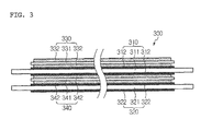
- FIG. 3 illustrates a cross-sectional view of a jelly-roll type electrode assembly using separators with porous coating layers formed only in areas where the separators are in contact with an anode and a cathode.
- the cathode and the anode in each of the figures may be used interchangeably.
- a jelly-roll type electrode assembly for a battery for example, a cylindrical battery is constructed by laminating a cathode, an anode and separators, and winding the laminate.
- Such an electrode assembly is illustrated in FIG. 1 .
- the jelly-roll type electrode assembly 100 includes a cathode 130, an anode 140, and separators 110 and 120 interposed between the cathode plate and the anode plate.
- the jelly-roll type electrode assembly 100 has a core around which the cathode 130 and the separators 110 are rolled.
- the separators 110 and 120 which are generally produced by elongation, thermally shrinks.
- the cathode 130 may be brought into contact with the anode 140, which poses a risk of fire.
- the electrode assembly 200 includes a cathode 230, a first separator 210, an anode 240 and a second separator 220 laminated in this order.
- the first separator 210 includes a porous substrate 211 and porous coating layers 212 formed on both surfaces of the porous substrate 211.
- the second separator 220 includes a porous substrate 221 and porous coating layers 222 formed on both surfaces of the porous substrate 221.
- Each of the porous coating layers 212 and 222 includes a mixture of inorganic particles and a binder polymer.
- the porous coating layers 212 and 222 enhance the heat resistance of the first and second separators 210 and 220, respectively.
- the electrode assembly 200 is wound in the form of a jelly roll configuration using a mandrel.
- the porous coating layers 212 and 222 may be separated from the separators 210 and 220, respectively.
- the porous coating layers 212 and 222 may also be separated from the separators 210 and 220, respectively, during cutting of the separators in the course of the construction of the electrode assembly and during taping after winding.
- the porous coating layers separated from the separators cause the occurrence of defects during battery assembly, resulting in a reduction in battery assembly yield.
- an organic binder may be used in an excess amount. In this case, however, the resistance of the separators increases, which is a cause of poor performance of an electrochemical device.
- the electrode assembly 300 of the present disclosure includes a cathode 330, a first separator 310, an anode 340 and a second separator 320 laminated in this order.
- the first separator 310 includes a porous substrate 311 and porous coating layers 312 formed on both surfaces of the porous substrate 311.
- the second separator 320 includes a porous substrate 321 and porous coating layers 322 formed on both surfaces of the porous substrate 321.
- Each of the porous coating layers 312 and 322 includes a mixture of inorganic particles and a binder polymer.
- the porous coating layers 312 and 322 are formed only in areas where the separators are in contact with the anode 340 and the cathode 330.
- the porous coating layers 312 and 322 may be dimensioned to be slightly narrower or wider than the anode 340 and the cathode 330. It is preferred that the porous coating layers 312 and 322 are larger in width than the electrodes 340 and 330. Some portions of the porous substrates 311 and 321 are not coated with the porous coating layers 312 and 322, respectively.
- the uncoated portions of the separators 310 and 320 are not limited to particular length ranges. The lengths of the uncoated portions may be varied depending on situations. Alternatively, each of the substrates 310 and 320 may have a porous coating layer formed on at least one surface of the porous substrate.
- the porous coating layers are formed only in areas where the separators are in contact with the anode and the cathode. Due to this construction, the porous coating layers 312 and 322 can be prevented from being separated from the separators during removal of a mandrel after winding in the course of the fabrication of an electrochemical device. In addition, the contact between the porous coating layers and a mandrel during winding is blocked so that the problem of poor winding resulting from different surface friction characteristics can be solved.
- porous coating layers formed on the separators may be in contact with and be adhered to the mandrel, which increases the possibility that the porous coating layers may be separated from the separators or the winding may be unsatisfactory in the course of the construction of the electrode assembly.
- the electrode assembly of the present disclosure is constructed such that the porous coating layers are not formed in areas where the separators are in contact with a mandrel, which reduces the risk of separation of the porous coating layers and poor winding.
- the reduced risk of separation of the porous coating layers can contribute to a reduction in the amount of the binder polymer used. This leads to a reduction in the resistance of the separators, and as a result, an electrochemical device including the electrode assembly is expected to have improved performance.
- the porous coating layers 312 and 322 of the separators 310 and 320 are formed by intermittent coating such that they are not formed in portions of the separators to be cut during subsequent processing. This can prevent the porous coating layers 312 and 322 from being separated from the separators upon cutting of the separators in the course of the construction of the electrode assembly. A taping process is required to fix the electrode assembly after winding. Since none of the porous coating layers are formed on the outermost surface of the electrode assembly, the porous coating layers can be prevented from being separated from the separators in the taping process.
- each of the porous coating layers is composed of a mixture of inorganic particles and a binder polymer.
- the binder polymer attaches (that is, connects and fixes) the inorganic particles to each other so as to maintain a state in which the inorganic particles are bound to each other.
- the binder polymer also functions to maintain a state in which the porous coating layers are bound to the corresponding porous substrates.
- the inorganic particles of the porous coating layers are in substantial contact with each other and have a closest packed structure. Interstitial volumes created between the inorganic particles in contact with each other become pores of the porous coating layers.
- the jelly-roll type electrode assembly is inserted into a battery case to fabricate a battery.
- the battery case may be a cylindrical or prismatic can.
- the battery case may be a pouch.
- a conventional electrode assembly is inserted into a battery case to fabricate a battery, a large surface frictional force of the electrode assembly impedes the fabrication of the battery.
- the jelly-roll type electrode assembly of the present disclosure may optionally use another separator without a porous coating layer.
- the separator has an area sufficient to surround the outermost surface of the electrode assembly. In this case, the surface frictional force of the electrode assembly is not large because the separator without a porous coating layer is arranged on the outermost surface of the electrode assembly.
- porous coating layers may be separated from the electrode assembly by friction with the battery case.
- the porous coating layers are not exposed to the outermost surface of the jelly-roll type electrode assembly of the present disclosure, they can be prevented from being separated from the separators.
- Each of the porous substrates used in the present disclosure may include porous polyolefin.
- Examples of preferred materials for the porous polyolefin substrates include polyethylene, polypropylene, polybutylene and polypentene.
- the inorganic particles may be, for example, inorganic particles having a dielectric constant of at least 5 or inorganic particles having the ability to transport lithium ions.
- the inorganic particles having a dielectric constant of at least 5 are preferably selected from the group consisting of BaTiO 3 , Pb(Zr x , Ti 1-x )O 3 (PZT, 0 ⁇ x ⁇ 1), Pb 1-x La x Zr 1-y Ti y O 3 (PLZT, 0 ⁇ x ⁇ 1, 0 ⁇ y ⁇ 1), (1-x)Pb(Mg 1/3 Nb 2/3 )O 3-x PbTiO 3 (PMN-PT, 0 ⁇ x ⁇ 1), hafnia (HfO 2 ), SrTiO 3 , SnO 2 , CeO 2 , MgO, NiO, CaO, ZnO, ZrO 2 , SiO 2 , Y 2 O 3 , Al 2 O 3 , SiC and TiO 2 particles, and mixtures thereof.
- the inorganic particles having the ability to transport lithium ions are preferably selected from the group consisting of lithium phosphate (Li 3 PO 4 ) particles, lithium titanium phosphate (Li x Ti y (PO 4 ) 3 , 0 ⁇ x ⁇ 2, 0 ⁇ y ⁇ 3) particles, lithium aluminum titanium phosphate (Li x Al y Ti z (PO 4 ) 3 , 0 ⁇ x ⁇ 2, 0 ⁇ y ⁇ 1, 0 ⁇ z ⁇ 3) particles, (LiAlTiP) x O y type glass (0 ⁇ x ⁇ 4, 0 ⁇ y ⁇ 13) particles, lithium lanthanum titanate (Li x La y TiO 3 , 0 ⁇ x ⁇ 2, 0 ⁇ y ⁇ 3) particles, lithium germanium thiophosphate (Li x Ge y P z S w , 0 ⁇ x ⁇ 4, 0 ⁇ y ⁇ 1,
- the binder polymer may be selected from the group consisting of polyvinylidene fluoride-co-hexafluoropropylene, polyvinylidene fluoride-co-trichloroethylene, polymethyl methacrylate, polybutyl acrylate, polyacrylonitrile, polyvinylpyrrolidone, polyvinyl acetate, polyvinyl alcohol, polyethylene-co-vinyl acetate, polyethylene oxide, polyarylate, cellulose acetate, cellulose acetate butyrate, cellulose acetate propionate, cyanoethylpullulan, cyanoethyl polyvinyl alcohol, cyanoethyl cellulose, cyanoethyl sucrose, pullulan, carboxymethyl cellulose, and low molecular weight compounds having a molecular weight of 10,000 g/mol or lower.
- the weight ratios of the inorganic particles to the binder polymer in the porous coating layers are each independently from 50:50 to 99:1.
- the present disclosure also provides a secondary battery including the jelly-roll type electrode assembly and a case sealing and accommodating the electrode assembly together with an electrolyte.
- each of the electrodes can be produced by binding an electrode active material to an electrode current collector using suitable methods known in the art.
- the cathode active material may be any of those that are commonly used in cathodes of conventional electrochemical devices.
- particularly preferred cathode active materials include lithiated manganese oxides, lithiated cobalt oxides, lithiated nickel oxides, lithiated iron oxides, and composite oxides thereof.
- the anode active material may be any of those that are commonly used in anodes of conventional electrochemical devices.
- Non-limiting examples of particularly preferred anode active materials include lithium, lithium alloys, and lithium intercalation materials, such as carbon, petroleum coke, activated carbon, graphite and other carbon materials.
- Non-limiting examples of cathode current collectors suitable for use in the cathode include aluminum foils, nickel foils, and combinations thereof.
- Non-limiting examples of anode current collectors suitable for use in the anode include copper foils, gold foils, nickel foils, copper alloy foils, and combinations thereof.
- the electrolyte consists of a salt and an organic solvent capable of dissolving or dissociating the salt.
- the salt has a structure represented by A + B - wherein A + is an alkali metal cation, such as Li + , Na + , K + or a combination thereof, and B - is an anion, such as PF 6 - , BF 4 - , Cl - , Br - , I - , ClO 4 - , AsF 6 - , CH 3 CO 2 - , CF 3 SO 3 - , N(CF 3 SO 2 ) 2 - , C(CF 2 SO 2 ) 3 - or a combination thereof.
- organic solvents suitable for dissolving or dissociating the salt include, but are not limited to, propylene carbonate (PC), ethylene carbonate (EC), diethyl carbonate (DEC), dimethyl carbonate (DMC), dipropyl carbonate (DPC), dimethyl sulfoxide, acetonitrile, dimethoxyethane, diethoxyethane, tetrahydrofuran, N-methyl-2-pyrrolidone (NMP), ethyl methyl carbonate (EMC) and ⁇ -butyrolactone. These organic solvents may be used alone or as a mixture thereof.
- the electrolyte may be injected in any suitable step during fabrication of the battery depending on the manufacturing processes and desired physical properties of a final product. Specifically, the electrolyte may be injected before battery assembly or in the final step of battery assembly.
- the battery case may be any of those commonly used in the art. There is no restriction on the shape of the battery case according to the intended application of the battery.
- the battery case may be a cylindrical or prismatic can.
- the battery case may have a pouch or a coin shape.
- the present disclosure also provides a method for constructing the electrode assembly.
- the method of the present disclosure is carried out as follows.
- porous substrates are prepared.
- Each of the porous substrates may be made of porous polyolefin.
- the porous polyolefin substrates may be made of at least one polymer selected from the group consisting of polyethylene, polypropylene, polybutylene and polypentene.
- a slurry including a mixture of inorganic particles and a binder polymer is intermittently coated on one or both surfaces of each of the porous substrates to form porous coating layers, completing the production of a separator.
- the method for intermittent coating of the slurry is not particularly limited. Knife coating or slot die coating is preferred. For intermittent coating of the slurry by knife coating, a knife is allowed to come into periodic contact with the surface of the porous substrate.
- the amount of the slurry supplied from a pump is controlled such that the slurry is discontinuously supplied to the surface of the porous substrate.
- the separators are laminated alternately with a cathode and an anode, followed by winding to construct the jelly-roll type electrode assembly in which the separators having the porous coating layers are formed only in areas where the separators are in contact with the anode and the cathode.
- Example 1 Separator having porous coating layer formed at one surface thereof
- PVdF-CTFE Polyvinylidene fluoride-co-chlorotrifluoroethylene
- cyanoethylpullulan in a weight ratio of 10:2 were added to and dissolved in acetone at 50 °C for about 12 hr.
- Al 2 O 3 powder in such an amount that the weight ratio of the polymers to the inorganic particles was 5:95.
- the inorganic particles were crushed and dispersed in the solution by ball milling for at least 12 hr to prepare a slurry.
- the inorganic particles of the slurry had an average particle size of 600 nm.
- the slurry was coated to a thickness of 4 ⁇ m on one surface of a 12 ⁇ m thick porous polyolefin membrane (porosity 40%) using a slot die coater.
- the amount of the slurry supplied was controlled such that about 90 mm long uncoated portions were formed on both ends of the porous membrane.
- the coated substrate was passed through a drier whose temperature was set to 50 °C to remove the solvent, completing the production of a separator.
- the bonding strength between the porous polyethylene membrane and the coating layer was as low as 10 gf/cm. Despite the low bonding strength, the inorganic particles did not fall off from the coating layer in the course of the fabrication of a cylindrical battery including holding the uncoated portions of the separator by a mandrel during assembly.
- example 2 Separator having porous coating layers formed at both surfaces thereof
- a slurry was prepared in the same manner as in Example 1.
- the slurry was coated to thicknesses of 2 ⁇ m on both surfaces of a 12 ⁇ m thick porous polyolefin membrane (porosity 40%) using a dip coater.
- a knife was allowed to come into periodic contact with the surfaces of the porous membrane such that about 90 mm long uncoated portions were formed on both ends of the porous membrane.
- the coated substrate was passed through a drier whose temperature was set to 50 °C to remove the solvent, completing the production of a separator.
- the bonding strength between the porous polyethylene membrane and the coating layers was as low as 15 gf/cm. Despite the low bonding strength, the inorganic particles did not fall off from the coating layers in the course of the fabrication of a cylindrical battery including holding the uncoated portions of the separator by a mandrel during assembly.
- Comparative Example 1 Separator having porous coating layers
- a separator was produced in the same manner as in Example 2, except that an uncoated portion was not formed.
- the bonding strength between the porous polyethylene membrane and the coating layers was as low as 15 gf/cm, which is at the same level as that in Example 2.
- the inorganic particles fell off from the coating layers when the coating layers were held by a mandrel during assembly.
Landscapes
- Chemical & Material Sciences (AREA)
- Chemical Kinetics & Catalysis (AREA)
- Electrochemistry (AREA)
- General Chemical & Material Sciences (AREA)
- Engineering & Computer Science (AREA)
- Manufacturing & Machinery (AREA)
- Composite Materials (AREA)
- Inorganic Chemistry (AREA)
- Materials Engineering (AREA)
- Cell Separators (AREA)
- Secondary Cells (AREA)
- Battery Electrode And Active Subsutance (AREA)
Abstract
Description
- The present disclosure relates to an electrode assembly for a secondary battery and a method for constructing the electrode assembly. More specifically, the present disclosure relates to an electrode assembly for a secondary battery which uses separators with porous coating layers to achieve improved heat resistance.
- This application claims priorities to Korean Patent Application No.
10-2011-0025851 - Recently, there has been growing interest in energy storage technologies. As the application fields of energy storage technologies have been extended to mobile phones, camcorders, notebook computers and even electric cars, efforts have increasingly been made towards the research and development of electrochemical devices. In this aspect, electrochemical devices have attracted the most attention. The development of secondary batteries capable of repeatedly charging and discharging has been the focus of particular interest. In recent years, extensive research and development has been conducted to design new electrodes and batteries for the purpose of improving capacity density and specific energy of the batteries.
- Many secondary batteries are currently available. Lithium secondary batteries developed in the early 1990's s have received a great deal of attention due to their advantages of higher operating voltages and much higher energy densities than conventional batteries using aqueous electrolyte solutions, such as Ni-MH batteries, Ni-Cd batteries and H2SO4-Pb batteries.
- Generally, a secondary battery is fabricated by laminating or winding one or more unit cells, each of which includes a cathode, an anode and a separator interposed between the anode and the cathode, accommodating the laminated or wound unit cells in a metal can or a laminate sheet case, and injecting or impregnating an electrolyte solution thereinto.
- Constituent electrode assemblies of secondary batteries have a cathode/separator/anode structure and are broadly classified into jelly-roll (i.e. winding) and stack (i.e. laminate) types by the constructions they have. A folding (jelly-roll) type electrode assembly is constructed by interposing a separator between a cathode and an anode, each of which is in the form of a long sheet to which an active material is applied, and winding the electrode structure. A stack type electrode assembly is constructed by sequentially laminating a plurality of cathodes and anodes, each of which has a predetermined size, between which separators are interposed. The jelly-roll type electrode assembly is easy to construct and has an advantage of high energy density per unit weight.
- Porous polyolefin substrates are commonly used as separators of lithium secondary batteries including jelly-roll type electrode assemblies. Porous polyolefin substrates tend to undergo extreme thermal shrinkage at temperatures of 100 °C or higher due to their material characteristics and production processes including elongation. Under such circumstance, the introduction of an organic-inorganic porous coating layer into a separator has been suggested as an approach aimed at achieving improved heat resistance. However, when a mandrel is withdrawn or the separator is cut after winding in the course of the fabrication of an electrochemical device, defects may be caused. For example, the inorganic particles may fall off from the organic-inorganic porous coating layer or the organic-inorganic porous coating layer may be separated from the separator.
- The present disclosure is designed to solve the problems of the prior art, and therefore it is an object of the present disclosure to provide an electrode assembly with improved heat resistance from which the separation of organic-inorganic porous coating layers is not possible in the course of the fabrication of an electrochemical device, and a method for constructing the electrode assembly.
- According to an aspect of the present disclosure, there is provided a jelly-roll type electrode assembly including an anode, a cathode, and separators interposed between the anode and the cathode and having a greater length than width, wherein each of the separators is longer than the anode and the cathode and has a porous substrate and porous coating layers formed on both surfaces of the porous substrate and including a mixture of inorganic particles and a binder polymer, and wherein the porous coating layers are formed only in areas where the separators are in contact with the anode and the cathode.
- Each of the porous substrates may include porous polyolefin. Examples of preferred materials for the porous polyolefin substrates include polyethylene, polypropylene, polybutylene and polypentene.
- As the inorganic particles, there may be used, for example, inorganic particles having a dielectric constant of at least 5 or inorganic particles having the ability to transport lithium ions.
- Examples of preferred materials for the inorganic particles having a dielectric constant of at least 5 include BaTiO3, Pb(Zrx, Ti1x)O3 (PZT, 0 < x < 1), Pb1-xLaxZr1-yTiyO3 (PLZT, 0 < x < 1, 0 < y < 1), (1-x)Pb(Mg1/3Mb2/3)O3-xPbTiO3 (PMN-PT, 0 < x < 1), hafnia (HfO2), SrTiO3, SnO2, CeO2, MgO, NiO, CaO, ZnO, ZrO2, SiO2, Y2O3, Al2O3, SiC and TiO2.
- Examples of preferred materials for the inorganic particles having the ability to transport lithium ions include lithium phosphate (Li3PO4), lithium titanium phosphate (LixTiy(PO4)3, 0 < x < 2, 0 < y < 3), lithium aluminum titanium phosphate (LixAlyTiz (PO4)3, 0 < x < 2, 0 < y < 1, 0 < z < 3), (LiAlTiP)xOy type glass (0 < x < 4, 0 < y < 13), lithium lanthanum titanate (LixLayTiO3, 0 < x < 2, 0 < y < 3), lithium germanium thiophosphate (LixGeyPzSw, 0 < x < 4, 0 < y < 1, 0 < z < 1, 0 < w < 5), lithium nitride (LixNy, 0 < x < 4, 0 < y < 2), SiS2 type glass (LixSiySz, 0 < x < 3, 0 < y < 2, 0 < z < 4) and P2S5 type glass (LixPySz, 0 < x < 3, 0 < y < 3, 0 < z < 7).
- As the binder polymer, there may be used, for example, polyvinylidene fluoride-co-hexafluoropropylene, polyvinylidene fluoride-co-trichloroethylene, polymethyl methacrylate, polybutyl acrylate, polyacrylonitrile, polyvinylpyrrolidone, polyvinyl acetate, polyvinyl alcohol, polyethylene-co-vinyl acetate, polyethylene oxide, polyarylate, cellulose acetate, cellulose acetate butyrate, cellulose acetate propionate, cyanoethylpullulan, cyanoethyl polyvinyl alcohol, cyanoethyl cellulose, cyanoethyl sucrose, pullulan, carboxymethyl cellulose, or a low molecular weight compound having a molecular weight of 10,000 g/mol or lower.
- Preferably, the weight ratios of the inorganic particles to the binder polymer in the porous coating layers are each independently from 50:50 to 99:1.
- According to another aspect of the present disclosure, there is provided a secondary battery including the electrode assembly and a case sealing and accommodating the electrode assembly together with an electrolyte.
- The jelly-roll type electrode assembly of the present disclosure is constructed to include separators having organic-inorganic porous coating layers with good heat resistance formed only in areas where the separators are in contact with an anode and a cathode. This construction can prevent the porous coating layers from being separated from the separators when a mandrel is withdrawn or the separators are cut after winding in the course of the fabrication of the electrochemical device, while ensuring high thermal stability of the battery.
- Furthermore, the contact between the porous coating layers and a mandrel during winding is blocked so that the problem of poor winding resulting from different surface friction characteristics can be solved. The electrode assembly of the present disclosure is constructed such that none of the porous coating layers are formed on the outermost surface of the electrode assembly to which a tape is to be adhered during subsequent processing. Due to this construction, the porous coating layers can be prevented from being separated from the separators.
- The accompanying drawings illustrate preferred embodiments of the present disclosure and together with the foregoing disclosure, serve to provide further understanding of the technical spirit of the present disclosure. However, the present disclosure is not to be construed as being limited to the drawings.
-
FIG. 1 is a cross-sectional view of a jelly-roll type electrode assembly using separators without a porous coating layer according to an embodiment. -
FIG. 2 is a cross-sectional view of a jelly-roll type electrode assembly using separators with porous coating layers according to an embodiment. -
FIG. 3 is a cross-sectional view of a jelly-roll type electrode assembly using separators with porous coating layers formed only in areas where the separators are in contact with an anode and a cathode. -
- 100, 200, 300: Electrode assemblies
- 110, 210, 310: First separators
- 211, 221, 311, 321: Porous substrates
- 212, 222, 312, 322: Porous coating layers
- 120, 220, 320: Second separators
- 130, 230, 330: Cathodes
- 231, 241, 331, 341: Current collectors
- 232, 332: Cathode active material layers
- 140, 240, 340: Anodes
- 242, 342: Anode active material layers
- Hereinafter, preferred embodiments of the present disclosure will be described in detail with reference to the accompanying drawings. Prior to the description, it should be understood that the terms used in the specification and the appended claims should not be construed as limited to general and dictionary meanings, but interpreted based on the meanings and concepts corresponding to technical aspects of the present disclosure on the basis of the principle that the inventor is allowed to define terms appropriately for the best explanation.
-
FIG. 1 illustrates a cross-sectional view of a jelly-roll type electrode assembly using separators without a porous coating layer according to an embodiment,FIG. 2 illustrates a cross-sectional view of a jelly-roll type electrode assembly using separators, each of which has porous coating layers formed on both surfaces thereof, according to an embodiment, andFIG. 3 illustrates a cross-sectional view of a jelly-roll type electrode assembly using separators with porous coating layers formed only in areas where the separators are in contact with an anode and a cathode. The cathode and the anode in each of the figures may be used interchangeably. However, the description proposed herein is just a preferable example for the purpose of illustrations only, not intended to limit the scope of the disclosure, so it should be understood that other equivalents and modifications could be made thereto without departing from the spirit and scope of the disclosure at the time of filing the present application. - Generally, a jelly-roll type electrode assembly for a battery, for example, a cylindrical battery is constructed by laminating a cathode, an anode and separators, and winding the laminate. Such an electrode assembly is illustrated in
FIG. 1 . - Referring to
FIG. 1 , the jelly-rolltype electrode assembly 100 includes acathode 130, ananode 140, andseparators type electrode assembly 100 has a core around which thecathode 130 and theseparators 110 are rolled. When the jelly-rolltype electrode assembly 100 generates heat during charge or use, theseparators cathode 130 may be brought into contact with theanode 140, which poses a risk of fire. - Referring to
FIG. 2 , theelectrode assembly 200 includes acathode 230, afirst separator 210, ananode 240 and a second separator 220 laminated in this order. Thefirst separator 210 includes a porous substrate 211 andporous coating layers 212 formed on both surfaces of the porous substrate 211. The second separator 220 includes a porous substrate 221 and porous coating layers 222 formed on both surfaces of the porous substrate 221. Each of theporous coating layers 212 and 222 includes a mixture of inorganic particles and a binder polymer. Theporous coating layers 212 and 222 enhance the heat resistance of the first andsecond separators 210 and 220, respectively. Due to this enhanced heat resistance, the contact between thecathode 230 and theanode 240 is blocked so that short circuits between the electrodes can be prevented. Theelectrode assembly 200 is wound in the form of a jelly roll configuration using a mandrel. When the mandrel is removed after winding, theporous coating layers 212 and 222 may be separated from theseparators 210 and 220, respectively. Theporous coating layers 212 and 222 may also be separated from theseparators 210 and 220, respectively, during cutting of the separators in the course of the construction of the electrode assembly and during taping after winding. The porous coating layers separated from the separators cause the occurrence of defects during battery assembly, resulting in a reduction in battery assembly yield. For the purpose of preventing the separation of the porous coating layers, an organic binder may be used in an excess amount. In this case, however, the resistance of the separators increases, which is a cause of poor performance of an electrochemical device. - Referring to
FIG. 3 , theelectrode assembly 300 of the present disclosure includes acathode 330, afirst separator 310, ananode 340 and asecond separator 320 laminated in this order. Thefirst separator 310 includes aporous substrate 311 andporous coating layers 312 formed on both surfaces of theporous substrate 311. Thesecond separator 320 includes aporous substrate 321 andporous coating layers 322 formed on both surfaces of theporous substrate 321. Each of theporous coating layers porous coating layers anode 340 and thecathode 330. Theporous coating layers anode 340 and thecathode 330. It is preferred that theporous coating layers electrodes porous substrates porous coating layers separators substrates electrode assembly 300 of the present disclosure, the porous coating layers are formed only in areas where the separators are in contact with the anode and the cathode. Due to this construction, theporous coating layers - The
porous coating layers separators porous coating layers - As described above, each of the porous coating layers is composed of a mixture of inorganic particles and a binder polymer. In each of the porous coating layers, the binder polymer attaches (that is, connects and fixes) the inorganic particles to each other so as to maintain a state in which the inorganic particles are bound to each other. The binder polymer also functions to maintain a state in which the porous coating layers are bound to the corresponding porous substrates. The inorganic particles of the porous coating layers are in substantial contact with each other and have a closest packed structure. Interstitial volumes created between the inorganic particles in contact with each other become pores of the porous coating layers.
- After winding, the jelly-roll type electrode assembly is inserted into a battery case to fabricate a battery. The battery case may be a cylindrical or prismatic can. Alternatively, the battery case may be a pouch. When a conventional electrode assembly is inserted into a battery case to fabricate a battery, a large surface frictional force of the electrode assembly impedes the fabrication of the battery. In view of this, the jelly-roll type electrode assembly of the present disclosure may optionally use another separator without a porous coating layer. The separator has an area sufficient to surround the outermost surface of the electrode assembly. In this case, the surface frictional force of the electrode assembly is not large because the separator without a porous coating layer is arranged on the outermost surface of the electrode assembly. When a conventional jelly-roll type electrode assembly is inserted into a battery case, porous coating layers may be separated from the electrode assembly by friction with the battery case. In contrast, since the porous coating layers are not exposed to the outermost surface of the jelly-roll type electrode assembly of the present disclosure, they can be prevented from being separated from the separators.
- Each of the porous substrates used in the present disclosure may include porous polyolefin. Examples of preferred materials for the porous polyolefin substrates include polyethylene, polypropylene, polybutylene and polypentene.
- The inorganic particles may be, for example, inorganic particles having a dielectric constant of at least 5 or inorganic particles having the ability to transport lithium ions.
- The inorganic particles having a dielectric constant of at least 5 are preferably selected from the group consisting of BaTiO3, Pb(Zrx, Ti1-x)O3 (PZT, 0 < x < 1), Pb1-xLaxZr1-yTiyO3 (PLZT, 0 < x < 1, 0 < y < 1), (1-x)Pb(Mg1/3Nb2/3)O3-xPbTiO3 (PMN-PT, 0 < x < 1), hafnia (HfO2), SrTiO3, SnO2, CeO2, MgO, NiO, CaO, ZnO, ZrO2, SiO2, Y2O3, Al2O3, SiC and TiO2 particles, and mixtures thereof.
- The inorganic particles having the ability to transport lithium ions are preferably selected from the group consisting of lithium phosphate (Li3PO4) particles, lithium titanium phosphate (LixTiy(PO4)3, 0 < x < 2, 0 < y < 3) particles, lithium aluminum titanium phosphate (LixAlyTiz(PO4)3, 0 < x < 2, 0 < y < 1, 0 < z < 3) particles, (LiAlTiP)xOy type glass (0 < x < 4, 0 < y < 13) particles, lithium lanthanum titanate (LixLayTiO3, 0 < x < 2, 0 < y < 3) particles, lithium germanium thiophosphate (LixGeyPzSw, 0 < x < 4, 0 < y < 1, 0 < z < 1, 0 < w < 5) particles, lithium nitride (LixNy, 0 < x < 4, 0 < y < 2) particles, SiS2 type glass (LixSiySz, 0 < x < 3, 0 < y < 2, 0 < z < 4) particles, P2S5 type glass (LixPySz, 0 < x < 3, 0 < y < 3, 0 < z < 7) particles, and mixtures thereof.
- The binder polymer may be selected from the group consisting of polyvinylidene fluoride-co-hexafluoropropylene, polyvinylidene fluoride-co-trichloroethylene, polymethyl methacrylate, polybutyl acrylate, polyacrylonitrile, polyvinylpyrrolidone, polyvinyl acetate, polyvinyl alcohol, polyethylene-co-vinyl acetate, polyethylene oxide, polyarylate, cellulose acetate, cellulose acetate butyrate, cellulose acetate propionate, cyanoethylpullulan, cyanoethyl polyvinyl alcohol, cyanoethyl cellulose, cyanoethyl sucrose, pullulan, carboxymethyl cellulose, and low molecular weight compounds having a molecular weight of 10,000 g/mol or lower.
- Preferably, the weight ratios of the inorganic particles to the binder polymer in the porous coating layers are each independently from 50:50 to 99:1.
- The present disclosure also provides a secondary battery including the jelly-roll type electrode assembly and a case sealing and accommodating the electrode assembly together with an electrolyte.
- There is no particular restriction on the production methods of the cathode and the anode. Each of the electrodes can be produced by binding an electrode active material to an electrode current collector using suitable methods known in the art. The cathode active material may be any of those that are commonly used in cathodes of conventional electrochemical devices. Non-limiting examples of particularly preferred cathode active materials include lithiated manganese oxides, lithiated cobalt oxides, lithiated nickel oxides, lithiated iron oxides, and composite oxides thereof. The anode active material may be any of those that are commonly used in anodes of conventional electrochemical devices. Non-limiting examples of particularly preferred anode active materials include lithium, lithium alloys, and lithium intercalation materials, such as carbon, petroleum coke, activated carbon, graphite and other carbon materials. Non-limiting examples of cathode current collectors suitable for use in the cathode include aluminum foils, nickel foils, and combinations thereof. Non-limiting examples of anode current collectors suitable for use in the anode include copper foils, gold foils, nickel foils, copper alloy foils, and combinations thereof.
- The electrolyte consists of a salt and an organic solvent capable of dissolving or dissociating the salt. The salt has a structure represented by A+B- wherein A+ is an alkali metal cation, such as Li+, Na+, K+ or a combination thereof, and B- is an anion, such as PF6 -, BF4 -, Cl-, Br-, I-, ClO4 -, AsF6 -, CH3CO2 -, CF3SO3 -, N(CF3SO2)2 -, C(CF2SO2)3 - or a combination thereof. Examples of organic solvents suitable for dissolving or dissociating the salt include, but are not limited to, propylene carbonate (PC), ethylene carbonate (EC), diethyl carbonate (DEC), dimethyl carbonate (DMC), dipropyl carbonate (DPC), dimethyl sulfoxide, acetonitrile, dimethoxyethane, diethoxyethane, tetrahydrofuran, N-methyl-2-pyrrolidone (NMP), ethyl methyl carbonate (EMC) and γ-butyrolactone. These organic solvents may be used alone or as a mixture thereof. The electrolyte may be injected in any suitable step during fabrication of the battery depending on the manufacturing processes and desired physical properties of a final product. Specifically, the electrolyte may be injected before battery assembly or in the final step of battery assembly.
- The battery case may be any of those commonly used in the art. There is no restriction on the shape of the battery case according to the intended application of the battery. For example, the battery case may be a cylindrical or prismatic can. Alternatively, the battery case may have a pouch or a coin shape.
- The present disclosure also provides a method for constructing the electrode assembly. The method of the present disclosure is carried out as follows.
- First, porous substrates are prepared. Each of the porous substrates may be made of porous polyolefin. The porous polyolefin substrates may be made of at least one polymer selected from the group consisting of polyethylene, polypropylene, polybutylene and polypentene. A slurry including a mixture of inorganic particles and a binder polymer is intermittently coated on one or both surfaces of each of the porous substrates to form porous coating layers, completing the production of a separator. The method for intermittent coating of the slurry is not particularly limited. Knife coating or slot die coating is preferred. For intermittent coating of the slurry by knife coating, a knife is allowed to come into periodic contact with the surface of the porous substrate. For intermittent coating by slot die coating, the amount of the slurry supplied from a pump is controlled such that the slurry is discontinuously supplied to the surface of the porous substrate.
- Thereafter, the separators are laminated alternately with a cathode and an anode, followed by winding to construct the jelly-roll type electrode assembly in which the separators having the porous coating layers are formed only in areas where the separators are in contact with the anode and the cathode.
- The present disclosure will be explained in detail with reference to the following examples. However, these examples may be embodied in various different forms and should not be construed as limiting the scope of the present disclosure. The examples are provided to more fully explain the present disclosure to those having ordinary knowledge in the art to which the present disclosure pertains.
- Polyvinylidene fluoride-co-chlorotrifluoroethylene (PVdF-CTFE) and cyanoethylpullulan in a weight ratio of 10:2 were added to and dissolved in acetone at 50 °C for about 12 hr. To the polymer solution was added Al2O3 powder in such an amount that the weight ratio of the polymers to the inorganic particles was 5:95. The inorganic particles were crushed and dispersed in the solution by ball milling for at least 12 hr to prepare a slurry. The inorganic particles of the slurry had an average particle size of 600 nm.
- The slurry was coated to a thickness of 4 µm on one surface of a 12 µm thick porous polyolefin membrane (porosity 40%) using a slot die coater. For intermittent coating, the amount of the slurry supplied was controlled such that about 90 mm long uncoated portions were formed on both ends of the porous membrane.
- Subsequently, the coated substrate was passed through a drier whose temperature was set to 50 °C to remove the solvent, completing the production of a separator. The bonding strength between the porous polyethylene membrane and the coating layer was as low as 10 gf/cm. Despite the low bonding strength, the inorganic particles did not fall off from the coating layer in the course of the fabrication of a cylindrical battery including holding the uncoated portions of the separator by a mandrel during assembly.
- A slurry was prepared in the same manner as in Example 1. The slurry was coated to thicknesses of 2 µm on both surfaces of a 12 µm thick porous polyolefin membrane (porosity 40%) using a dip coater. For intermittent coating of the slurry, a knife was allowed to come into periodic contact with the surfaces of the porous membrane such that about 90 mm long uncoated portions were formed on both ends of the porous membrane.
- Subsequently, the coated substrate was passed through a drier whose temperature was set to 50 °C to remove the solvent, completing the production of a separator. The bonding strength between the porous polyethylene membrane and the coating layers was as low as 15 gf/cm. Despite the low bonding strength, the inorganic particles did not fall off from the coating layers in the course of the fabrication of a cylindrical battery including holding the uncoated portions of the separator by a mandrel during assembly.
- A separator was produced in the same manner as in Example 2, except that an uncoated portion was not formed. The bonding strength between the porous polyethylene membrane and the coating layers was as low as 15 gf/cm, which is at the same level as that in Example 2. The inorganic particles fell off from the coating layers when the coating layers were held by a mandrel during assembly.
Claims (12)
- A jelly-roll type electrode assembly comprising an anode, a cathode, and separators interposed between the anode and the cathode and having a greater length than width,
wherein each of the separators is longer than the anode and the cathode and has a porous substrate and porous coating layers formed on both surfaces of the porous substrate and comprising a mixture of inorganic particles and a binder polymer, and
wherein the porous coating layers are formed only in areas where the separators are in contact with the anode and the cathode. - The jelly-roll type electrode assembly according to claim 1, wherein each of the porous substrates comprises porous polyolefin.
- The jelly-roll type electrode assembly according to claim 2, wherein each of the porous polyolefin substrates is made of at least one polymer selected from the group consisting of polyethylene, polypropylene, polybutylene and polypentene.
- The jelly-roll type electrode assembly according to claim 1, wherein the inorganic particles are selected from the group consisting of inorganic particles having a dielectric constant of at least 5, inorganic particles having the ability to transport lithium ions, and mixtures thereof.
- The jelly-roll type electrode assembly according to claim 4, wherein the inorganic particles having a dielectric constant of at least 5 are selected from the group consisting of BaTiO3, Pb(Zrx, Ti1x)O3 (PZT, 0 < x < 1), Pb1-xLaxZr1-yTiyO3 (PLZT, 0 < x < 1, 0 < y < 1), (1-x)Pb(Mg1/3Nb2/3)O3-xPbTiO3 (PMN-PT, 0 < x < 1), hafnia (HfO2), SrTiO3, SnO2, CeO2, MgO, NiO, CaO, ZnO, ZrO2, SiO2, Y2O3, Al2O3, SiC, TiO2 particles, and mixtures thereof.
- The jelly-roll type electrode assembly according to claim 4, wherein the inorganic particles having the ability to transport lithium ions are selected from the group consisting of lithium phosphate (Li3PO4) particles, lithium titanium phosphate (LixTiy(PO4)3, 0 < x < 2, 0 < y < 3) particles, lithium aluminum titanium phosphate (LixAlyTiz(PO4)3, 0 < x < 2, 0 < y < 1, 0 < z < 3) particles, (LiAlTiP)xOy type glass (0 < x < 4, 0 < y < 13) particles, lithium lanthanum titanate (LixLayTiO3, 0 < x < 2, 0 < y < 3) particles, lithium germanium thiophosphate (LixGeyPzSw, 0 < x < 4, 0 < y < 1, 0 < z < 1, 0 < w < 5) particles, lithium nitride (LixNy, 0 < x < 4, 0 < y < 2) particles, SiS2 type glass (LixSiySz, 0 < x < 3, 0 < y < 2, 0 < z < 4) particles, P2S5 type glass (LixPySz, 0 < x < 3, 0 < y < 3, 0 < z < 7) particles, and mixtures thereof
- The jelly-roll type electrode assembly according to claim 1, wherein the binder polymer is selected from the group consisting of polyvinylidene fluoride-co-hexafluoropropylene, polyvinylidene fluoride-co-trichloroethylene, polymethyl methacrylate, polybutyl acrylate, polyacrylonitrile, polyvinylpyrrolidone, polyvinyl acetate, polyvinyl alcohol, polyethylene-co-vinyl acetate, polyethylene oxide, polyarylate, cellulose acetate, cellulose acetate butyrate, cellulose acetate propionate, cyanoethylpullulan, cyanoethyl polyvinyl alcohol, cyanoethyl cellulose, cyanoethyl sucrose, pullulan, carboxymethyl cellulose, low molecular weight compounds having a molecular weight of 10,000 g/mol or lower, and mixtures thereof.
- The jelly-roll type electrode assembly according to claim 1, wherein the inorganic particles and the binder polymer are present in a weight ratio of 50:50 to 99:1.
- A secondary battery comprising the jelly-roll type electrode assembly according to any one of claims 1 to 8 and a case sealing and accommodating the electrode assembly together with an electrolyte.
- A method for constructing the jelly-roll type electrode assembly according to any one of claims 1 to 8, the method comprising:intermittently coating a slurry comprising a mixture of inorganic particles and a binder polymer on the surfaces of porous substrates to produce separators with porous coating layers; andalternately laminating the separators with a cathode and an anode, and winding to construct the jelly-roll type electrode assembly.
- The method according to claim 10, wherein the slurry is intermittently coated by knife coating while allowing a knife to come into periodic contact with the surfaces of the porous substrates.
- The method according to claim 10, wherein the slurry is intermittently coated by slot die coating while allowing the slurry to be discontinuously supplied to the surfaces of the porous substrates.
Applications Claiming Priority (2)
| Application Number | Priority Date | Filing Date | Title |
|---|---|---|---|
| KR1020110025851A KR101453037B1 (en) | 2011-03-23 | 2011-03-23 | Electrode assembly for secondary battery preparation method of electrode assembly thereof |
| PCT/KR2011/008514 WO2012128440A1 (en) | 2011-03-23 | 2011-11-09 | Electrode assembly and method for manufacturing same |
Publications (3)
| Publication Number | Publication Date |
|---|---|
| EP2690696A1 true EP2690696A1 (en) | 2014-01-29 |
| EP2690696A4 EP2690696A4 (en) | 2014-09-03 |
| EP2690696B1 EP2690696B1 (en) | 2016-01-13 |
Family
ID=46879554
Family Applications (1)
| Application Number | Title | Priority Date | Filing Date |
|---|---|---|---|
| EP11861652.3A Active EP2690696B1 (en) | 2011-03-23 | 2011-11-09 | Electrode assembly and method for manufacturing same |
Country Status (6)
| Country | Link |
|---|---|
| US (1) | US9178201B2 (en) |
| EP (1) | EP2690696B1 (en) |
| JP (1) | JP5752815B2 (en) |
| KR (1) | KR101453037B1 (en) |
| CN (1) | CN103443986B (en) |
| WO (1) | WO2012128440A1 (en) |
Families Citing this family (26)
| Publication number | Priority date | Publication date | Assignee | Title |
|---|---|---|---|---|
| JP6036107B2 (en) * | 2012-09-27 | 2016-11-30 | 株式会社Gsユアサ | Electricity storage element |
| MX360816B (en) | 2012-11-20 | 2018-11-15 | Mederis Diabetes Llc | Improved peptide pharmaceuticals for insulin resistance. |
| EP2770559B1 (en) | 2012-12-12 | 2017-11-22 | LG Chem, Ltd. | Cable-type secondary battery |
| KR101479460B1 (en) | 2012-12-12 | 2015-01-05 | 주식회사 엘지화학 | Electrode for a secondary battery, secondary battery and cable-type secondary battery including the same |
| KR101738734B1 (en) | 2013-09-26 | 2017-06-08 | 주식회사 엘지화학 | Pouch type secondary battery |
| KR101676406B1 (en) * | 2013-10-31 | 2016-11-15 | 주식회사 엘지화학 | Stack-folding typed electrode assembly |
| PT3155017T (en) | 2014-05-28 | 2024-05-14 | Mederis Diabetes Llc | Improved peptide pharmaceuticals for insulin resistance |
| KR102279223B1 (en) * | 2014-11-25 | 2021-07-19 | 삼성에스디아이 주식회사 | Electrode assembly having protection tape and rechargeable battery having thereof |
| PL3190652T3 (en) | 2014-12-08 | 2020-02-28 | Lg Chem, Ltd. | Electrode assembly having improved safety, manufacturing method therefor and electrochemical element comprising electrode assembly |
| PL3244475T3 (en) * | 2015-09-02 | 2021-05-17 | Lg Chem, Ltd. | Separation membrane comprising adhesive coating parts with different adhesion forces, and electrode assembly comprising same |
| KR102546315B1 (en) * | 2015-09-25 | 2023-06-21 | 삼성전자주식회사 | Electrode composite separator assembly for lithium battery and lithium battery including the same |
| KR102082654B1 (en) * | 2016-02-11 | 2020-02-28 | 주식회사 엘지화학 | Unit Cell for Secondary Battery Comprising Separator Having Inorganic Coating Portion, Adhesive Portion and Non-adhesive Portion |
| WO2017213443A1 (en) * | 2016-06-08 | 2017-12-14 | 주식회사 엘지화학 | Separator and electrochemical device comprising same |
| US10263257B2 (en) * | 2016-09-22 | 2019-04-16 | Grst International Limited | Electrode assemblies |
| GB201704295D0 (en) | 2017-03-17 | 2017-05-03 | Dyson Technology Ltd | Energy storage device |
| GB201704294D0 (en) | 2017-03-17 | 2017-05-03 | Dyson Technology Ltd | Energy storage device |
| GB201704293D0 (en) | 2017-03-17 | 2017-05-03 | Dyson Technology Ltd | Energy storage device |
| GB201704292D0 (en) * | 2017-03-17 | 2017-05-03 | Dyson Technology Ltd | Energy storage device |
| KR102273100B1 (en) * | 2017-11-01 | 2021-07-02 | 주식회사 엘지에너지솔루션 | Electrode assembly and method of stabilizing secondary battery |
| EP4506017A3 (en) | 2018-01-03 | 2025-05-14 | Mederis Diabetes, LLC | Improved peptide pharmaceuticals for treatment of nash and other disorders |
| KR102753165B1 (en) * | 2018-12-10 | 2025-01-10 | 주식회사 엘지에너지솔루션 | Electrode assembly and secondary battery therewith the electrode assembly and battery pack therewith the secondary battery |
| US20230223658A1 (en) * | 2020-06-19 | 2023-07-13 | Varta Microbattery Gmbh | Lithium-ion cell with a high specific energy density |
| US20230344082A1 (en) * | 2020-10-06 | 2023-10-26 | Lg Energy Solution, Ltd. | Method for manufacturing separator for secondary battery, separator obtained therefrom and secondary battery including the same |
| CN117202924A (en) | 2020-12-07 | 2023-12-08 | 斯皮特弗尔制药有限责任公司 | Treatment options and methods for lowering blood glucose and/or weight using balanced GLP-1R and GCGR agonists |
| CN216015452U (en) | 2021-01-07 | 2022-03-11 | 广东维都利新能源有限公司 | Soft package lithium ion battery cell with insection sealing edge |
| CN118782724A (en) * | 2023-04-07 | 2024-10-15 | 宁德新能源科技有限公司 | Electrochemical devices and electronic devices |
Family Cites Families (24)
| Publication number | Priority date | Publication date | Assignee | Title |
|---|---|---|---|---|
| JP3371301B2 (en) * | 1994-01-31 | 2003-01-27 | ソニー株式会社 | Non-aqueous electrolyte secondary battery |
| US6444357B1 (en) * | 1999-05-19 | 2002-09-03 | Nec Tokin Corporation | Non-aqueous electrolyte secondary battery |
| WO2001039294A2 (en) * | 1999-11-23 | 2001-05-31 | Moltech Corporation | Methods of preparing electrochemical cells |
| KR100666821B1 (en) * | 2004-02-07 | 2007-01-09 | 주식회사 엘지화학 | Electrode with organic / inorganic composite porous coating layer and electrochemical device comprising the same |
| KR100590096B1 (en) * | 2004-04-29 | 2006-06-14 | 삼성에스디아이 주식회사 | Lithium secondary battery |
| ES3010715T3 (en) * | 2004-07-07 | 2025-04-04 | Lg Energy Solution Ltd | New organic/inorganic composite porous film and electrochemical device prepared thereby |
| US7372610B2 (en) * | 2005-02-23 | 2008-05-13 | Sage Electrochromics, Inc. | Electrochromic devices and methods |
| EP1780820A4 (en) * | 2005-03-02 | 2009-09-09 | Panasonic Corp | LITHIUM ION SECONDARY BATTERY AND METHOD OF MANUFACTURING THE SAME |
| US20090291355A1 (en) * | 2005-09-29 | 2009-11-26 | Sanyo Electric Co., Ltd. | Positive electrode for non-aqueous electrolyte battery, negative electrode for non-aqueous electrolyte battery, separator for non-aqueous electrolyte battery, and non-aqueous electrolyte battery using them |
| KR100731452B1 (en) * | 2005-12-29 | 2007-06-21 | 삼성에스디아이 주식회사 | Pole plate winding device and winding method of cylindrical battery |
| WO2007083731A1 (en) * | 2006-01-23 | 2007-07-26 | Matsushita Electric Industrial Co., Ltd. | Sealed battery |
| KR100791791B1 (en) * | 2006-03-10 | 2008-01-04 | 주식회사 엘지화학 | Electrode coated with a porous active layer, a manufacturing method and an electrochemical device having the same |
| US8332028B2 (en) * | 2006-11-28 | 2012-12-11 | Polyplus Battery Company | Protected lithium electrodes for electro-transport drug delivery |
| JP2008243660A (en) | 2007-03-28 | 2008-10-09 | Sanyo Electric Co Ltd | Nonaqueous electrolyte secondary battery |
| KR100999309B1 (en) * | 2007-06-04 | 2010-12-08 | 주식회사 엘지화학 | Separator with a porous coating layer and an electrochemical device having the same |
| KR20090031156A (en) * | 2007-09-21 | 2009-03-25 | 삼성에스디아이 주식회사 | Membrane Manufacturing Method and Apparatus for Fuel Cell |
| KR100966604B1 (en) * | 2007-11-19 | 2010-06-29 | 삼성에스디아이 주식회사 | Electrode assembly and secondary battery having same |
| US8377583B2 (en) * | 2008-01-30 | 2013-02-19 | Lg Chem, Ltd. | Separator for providing a uniting force to electrode and electrochemical cell containing the same |
| JP2009211857A (en) * | 2008-03-03 | 2009-09-17 | Sony Corp | Battery |
| KR101040482B1 (en) | 2008-03-04 | 2011-06-09 | 주식회사 엘지화학 | Separator coated with porous coating layer and electrochemical device having the same |
| KR100947072B1 (en) * | 2008-03-27 | 2010-04-01 | 삼성에스디아이 주식회사 | Electrode assembly and secondary battery having same |
| JP2010073339A (en) * | 2008-09-16 | 2010-04-02 | Panasonic Corp | Nonaqueous electrolyte secondary battery and its electrode |
| JP5299980B2 (en) * | 2008-12-19 | 2013-09-25 | エルジー ケム. エルティーディ. | High power lithium secondary battery |
| US9664974B2 (en) * | 2009-03-31 | 2017-05-30 | View, Inc. | Fabrication of low defectivity electrochromic devices |
-
2011
- 2011-03-23 KR KR1020110025851A patent/KR101453037B1/en active Active
- 2011-11-09 CN CN201180069515.1A patent/CN103443986B/en active Active
- 2011-11-09 JP JP2013557629A patent/JP5752815B2/en active Active
- 2011-11-09 WO PCT/KR2011/008514 patent/WO2012128440A1/en not_active Ceased
- 2011-11-09 EP EP11861652.3A patent/EP2690696B1/en active Active
-
2012
- 2012-09-14 US US13/616,799 patent/US9178201B2/en active Active
Also Published As
| Publication number | Publication date |
|---|---|
| KR101453037B1 (en) | 2014-10-21 |
| JP2014511554A (en) | 2014-05-15 |
| US9178201B2 (en) | 2015-11-03 |
| JP5752815B2 (en) | 2015-07-22 |
| CN103443986B (en) | 2015-12-02 |
| KR20120108212A (en) | 2012-10-05 |
| US20130004817A1 (en) | 2013-01-03 |
| CN103443986A (en) | 2013-12-11 |
| WO2012128440A1 (en) | 2012-09-27 |
| EP2690696B1 (en) | 2016-01-13 |
| EP2690696A4 (en) | 2014-09-03 |
Similar Documents
| Publication | Publication Date | Title |
|---|---|---|
| US9178201B2 (en) | Electrode assembly and method for constructing the same | |
| EP2696395B1 (en) | Separator and electrochemical device including same | |
| EP2541644B1 (en) | Manufacturing method for separator | |
| EP2840628B1 (en) | Method for manufacturing separator, separator formed thereby, and electrochemical device comprising said separator | |
| EP2779275B1 (en) | Separator, and electrochemical device comprising same | |
| EP2541643B1 (en) | Manufacturing method for separator, separator made therefrom, and manufacturing method for electrochemical device containing same | |
| US8778524B2 (en) | Electrochemical device with improved cycle characteristics | |
| EP4184641B1 (en) | Separator and electrochemical device having the same | |
| US9786890B2 (en) | Separator and electrochemical device having the same | |
| EP2750219A1 (en) | Method for manufacturing a separator, separator formed by same and electrochemical device having same | |
| US9276247B2 (en) | Separator and electrochemical device comprising the same | |
| KR101507499B1 (en) | Electrode assembly for secondary battery | |
| KR20180127759A (en) | Separator for lithium secondary battery and lithium secondary battery including the same |
Legal Events
| Date | Code | Title | Description |
|---|---|---|---|
| PUAI | Public reference made under article 153(3) epc to a published international application that has entered the european phase |
Free format text: ORIGINAL CODE: 0009012 |
|
| 17P | Request for examination filed |
Effective date: 20130903 |
|
| AK | Designated contracting states |
Kind code of ref document: A1 Designated state(s): AL AT BE BG CH CY CZ DE DK EE ES FI FR GB GR HR HU IE IS IT LI LT LU LV MC MK MT NL NO PL PT RO RS SE SI SK SM TR |
|
| DAX | Request for extension of the european patent (deleted) | ||
| A4 | Supplementary search report drawn up and despatched |
Effective date: 20140804 |
|
| RIC1 | Information provided on ipc code assigned before grant |
Ipc: H01M 10/05 20100101ALI20140729BHEP Ipc: H01M 10/04 20060101AFI20140729BHEP Ipc: B01D 1/26 20060101ALI20140729BHEP Ipc: H01M 2/14 20060101ALI20140729BHEP |
|
| REG | Reference to a national code |
Ref country code: DE Ref legal event code: R079 Ref document number: 602011022733 Country of ref document: DE Free format text: PREVIOUS MAIN CLASS: H01M0010040000 Ipc: H01M0002160000 |
|
| RIC1 | Information provided on ipc code assigned before grant |
Ipc: H01M 2/16 20060101AFI20150617BHEP Ipc: H01M 2/14 20060101ALI20150617BHEP |
|
| GRAP | Despatch of communication of intention to grant a patent |
Free format text: ORIGINAL CODE: EPIDOSNIGR1 |
|
| INTG | Intention to grant announced |
Effective date: 20150812 |
|
| GRAS | Grant fee paid |
Free format text: ORIGINAL CODE: EPIDOSNIGR3 |
|
| GRAA | (expected) grant |
Free format text: ORIGINAL CODE: 0009210 |
|
| AK | Designated contracting states |
Kind code of ref document: B1 Designated state(s): AL AT BE BG CH CY CZ DE DK EE ES FI FR GB GR HR HU IE IS IT LI LT LU LV MC MK MT NL NO PL PT RO RS SE SI SK SM TR |
|
| REG | Reference to a national code |
Ref country code: GB Ref legal event code: FG4D |
|
| REG | Reference to a national code |
Ref country code: CH Ref legal event code: EP |
|
| REG | Reference to a national code |
Ref country code: IE Ref legal event code: FG4D |
|
| REG | Reference to a national code |
Ref country code: AT Ref legal event code: REF Ref document number: 771038 Country of ref document: AT Kind code of ref document: T Effective date: 20160215 |
|
| REG | Reference to a national code |
Ref country code: DE Ref legal event code: R096 Ref document number: 602011022733 Country of ref document: DE |
|
| REG | Reference to a national code |
Ref country code: LT Ref legal event code: MG4D |
|
| REG | Reference to a national code |
Ref country code: NL Ref legal event code: MP Effective date: 20160113 |
|
| REG | Reference to a national code |
Ref country code: AT Ref legal event code: MK05 Ref document number: 771038 Country of ref document: AT Kind code of ref document: T Effective date: 20160113 |
|
| PG25 | Lapsed in a contracting state [announced via postgrant information from national office to epo] |
Ref country code: NL Free format text: LAPSE BECAUSE OF FAILURE TO SUBMIT A TRANSLATION OF THE DESCRIPTION OR TO PAY THE FEE WITHIN THE PRESCRIBED TIME-LIMIT Effective date: 20160113 |
|
| PG25 | Lapsed in a contracting state [announced via postgrant information from national office to epo] |
Ref country code: IT Free format text: LAPSE BECAUSE OF FAILURE TO SUBMIT A TRANSLATION OF THE DESCRIPTION OR TO PAY THE FEE WITHIN THE PRESCRIBED TIME-LIMIT Effective date: 20160113 Ref country code: ES Free format text: LAPSE BECAUSE OF FAILURE TO SUBMIT A TRANSLATION OF THE DESCRIPTION OR TO PAY THE FEE WITHIN THE PRESCRIBED TIME-LIMIT Effective date: 20160113 Ref country code: FI Free format text: LAPSE BECAUSE OF FAILURE TO SUBMIT A TRANSLATION OF THE DESCRIPTION OR TO PAY THE FEE WITHIN THE PRESCRIBED TIME-LIMIT Effective date: 20160113 Ref country code: HR Free format text: LAPSE BECAUSE OF FAILURE TO SUBMIT A TRANSLATION OF THE DESCRIPTION OR TO PAY THE FEE WITHIN THE PRESCRIBED TIME-LIMIT Effective date: 20160113 Ref country code: GR Free format text: LAPSE BECAUSE OF FAILURE TO SUBMIT A TRANSLATION OF THE DESCRIPTION OR TO PAY THE FEE WITHIN THE PRESCRIBED TIME-LIMIT Effective date: 20160414 Ref country code: NO Free format text: LAPSE BECAUSE OF FAILURE TO SUBMIT A TRANSLATION OF THE DESCRIPTION OR TO PAY THE FEE WITHIN THE PRESCRIBED TIME-LIMIT Effective date: 20160413 |
|
| PG25 | Lapsed in a contracting state [announced via postgrant information from national office to epo] |
Ref country code: LT Free format text: LAPSE BECAUSE OF FAILURE TO SUBMIT A TRANSLATION OF THE DESCRIPTION OR TO PAY THE FEE WITHIN THE PRESCRIBED TIME-LIMIT Effective date: 20160113 Ref country code: IS Free format text: LAPSE BECAUSE OF FAILURE TO SUBMIT A TRANSLATION OF THE DESCRIPTION OR TO PAY THE FEE WITHIN THE PRESCRIBED TIME-LIMIT Effective date: 20160513 Ref country code: PT Free format text: LAPSE BECAUSE OF FAILURE TO SUBMIT A TRANSLATION OF THE DESCRIPTION OR TO PAY THE FEE WITHIN THE PRESCRIBED TIME-LIMIT Effective date: 20160513 Ref country code: LV Free format text: LAPSE BECAUSE OF FAILURE TO SUBMIT A TRANSLATION OF THE DESCRIPTION OR TO PAY THE FEE WITHIN THE PRESCRIBED TIME-LIMIT Effective date: 20160113 Ref country code: AT Free format text: LAPSE BECAUSE OF FAILURE TO SUBMIT A TRANSLATION OF THE DESCRIPTION OR TO PAY THE FEE WITHIN THE PRESCRIBED TIME-LIMIT Effective date: 20160113 Ref country code: PL Free format text: LAPSE BECAUSE OF FAILURE TO SUBMIT A TRANSLATION OF THE DESCRIPTION OR TO PAY THE FEE WITHIN THE PRESCRIBED TIME-LIMIT Effective date: 20160113 Ref country code: SE Free format text: LAPSE BECAUSE OF FAILURE TO SUBMIT A TRANSLATION OF THE DESCRIPTION OR TO PAY THE FEE WITHIN THE PRESCRIBED TIME-LIMIT Effective date: 20160113 Ref country code: RS Free format text: LAPSE BECAUSE OF FAILURE TO SUBMIT A TRANSLATION OF THE DESCRIPTION OR TO PAY THE FEE WITHIN THE PRESCRIBED TIME-LIMIT Effective date: 20160113 |
|
| REG | Reference to a national code |
Ref country code: DE Ref legal event code: R097 Ref document number: 602011022733 Country of ref document: DE |
|
| PG25 | Lapsed in a contracting state [announced via postgrant information from national office to epo] |
Ref country code: EE Free format text: LAPSE BECAUSE OF FAILURE TO SUBMIT A TRANSLATION OF THE DESCRIPTION OR TO PAY THE FEE WITHIN THE PRESCRIBED TIME-LIMIT Effective date: 20160113 Ref country code: DK Free format text: LAPSE BECAUSE OF FAILURE TO SUBMIT A TRANSLATION OF THE DESCRIPTION OR TO PAY THE FEE WITHIN THE PRESCRIBED TIME-LIMIT Effective date: 20160113 |
|
| REG | Reference to a national code |
Ref country code: FR Ref legal event code: PLFP Year of fee payment: 6 |
|
| PLBE | No opposition filed within time limit |
Free format text: ORIGINAL CODE: 0009261 |
|
| STAA | Information on the status of an ep patent application or granted ep patent |
Free format text: STATUS: NO OPPOSITION FILED WITHIN TIME LIMIT |
|
| PG25 | Lapsed in a contracting state [announced via postgrant information from national office to epo] |
Ref country code: RO Free format text: LAPSE BECAUSE OF FAILURE TO SUBMIT A TRANSLATION OF THE DESCRIPTION OR TO PAY THE FEE WITHIN THE PRESCRIBED TIME-LIMIT Effective date: 20160113 Ref country code: SM Free format text: LAPSE BECAUSE OF FAILURE TO SUBMIT A TRANSLATION OF THE DESCRIPTION OR TO PAY THE FEE WITHIN THE PRESCRIBED TIME-LIMIT Effective date: 20160113 Ref country code: SK Free format text: LAPSE BECAUSE OF FAILURE TO SUBMIT A TRANSLATION OF THE DESCRIPTION OR TO PAY THE FEE WITHIN THE PRESCRIBED TIME-LIMIT Effective date: 20160113 Ref country code: CZ Free format text: LAPSE BECAUSE OF FAILURE TO SUBMIT A TRANSLATION OF THE DESCRIPTION OR TO PAY THE FEE WITHIN THE PRESCRIBED TIME-LIMIT Effective date: 20160113 |
|
| 26N | No opposition filed |
Effective date: 20161014 |
|
| PG25 | Lapsed in a contracting state [announced via postgrant information from national office to epo] |
Ref country code: BE Free format text: LAPSE BECAUSE OF FAILURE TO SUBMIT A TRANSLATION OF THE DESCRIPTION OR TO PAY THE FEE WITHIN THE PRESCRIBED TIME-LIMIT Effective date: 20160113 |
|
| PG25 | Lapsed in a contracting state [announced via postgrant information from national office to epo] |
Ref country code: SI Free format text: LAPSE BECAUSE OF FAILURE TO SUBMIT A TRANSLATION OF THE DESCRIPTION OR TO PAY THE FEE WITHIN THE PRESCRIBED TIME-LIMIT Effective date: 20160113 Ref country code: BG Free format text: LAPSE BECAUSE OF FAILURE TO SUBMIT A TRANSLATION OF THE DESCRIPTION OR TO PAY THE FEE WITHIN THE PRESCRIBED TIME-LIMIT Effective date: 20160413 |
|
| REG | Reference to a national code |
Ref country code: CH Ref legal event code: PL |
|
| PG25 | Lapsed in a contracting state [announced via postgrant information from national office to epo] |
Ref country code: CH Free format text: LAPSE BECAUSE OF NON-PAYMENT OF DUE FEES Effective date: 20161130 Ref country code: LI Free format text: LAPSE BECAUSE OF NON-PAYMENT OF DUE FEES Effective date: 20161130 |
|
| REG | Reference to a national code |
Ref country code: IE Ref legal event code: MM4A |
|
| PG25 | Lapsed in a contracting state [announced via postgrant information from national office to epo] |
Ref country code: LU Free format text: LAPSE BECAUSE OF NON-PAYMENT OF DUE FEES Effective date: 20161130 |
|
| REG | Reference to a national code |
Ref country code: FR Ref legal event code: PLFP Year of fee payment: 7 |
|
| PG25 | Lapsed in a contracting state [announced via postgrant information from national office to epo] |
Ref country code: IE Free format text: LAPSE BECAUSE OF NON-PAYMENT OF DUE FEES Effective date: 20161109 |
|
| PG25 | Lapsed in a contracting state [announced via postgrant information from national office to epo] |
Ref country code: HU Free format text: LAPSE BECAUSE OF FAILURE TO SUBMIT A TRANSLATION OF THE DESCRIPTION OR TO PAY THE FEE WITHIN THE PRESCRIBED TIME-LIMIT; INVALID AB INITIO Effective date: 20111109 Ref country code: CY Free format text: LAPSE BECAUSE OF FAILURE TO SUBMIT A TRANSLATION OF THE DESCRIPTION OR TO PAY THE FEE WITHIN THE PRESCRIBED TIME-LIMIT Effective date: 20160113 |
|
| PG25 | Lapsed in a contracting state [announced via postgrant information from national office to epo] |
Ref country code: MK Free format text: LAPSE BECAUSE OF FAILURE TO SUBMIT A TRANSLATION OF THE DESCRIPTION OR TO PAY THE FEE WITHIN THE PRESCRIBED TIME-LIMIT Effective date: 20160113 Ref country code: MC Free format text: LAPSE BECAUSE OF FAILURE TO SUBMIT A TRANSLATION OF THE DESCRIPTION OR TO PAY THE FEE WITHIN THE PRESCRIBED TIME-LIMIT Effective date: 20160113 |
|
| PG25 | Lapsed in a contracting state [announced via postgrant information from national office to epo] |
Ref country code: MT Free format text: LAPSE BECAUSE OF NON-PAYMENT OF DUE FEES Effective date: 20161109 |
|
| REG | Reference to a national code |
Ref country code: FR Ref legal event code: PLFP Year of fee payment: 8 |
|
| PG25 | Lapsed in a contracting state [announced via postgrant information from national office to epo] |
Ref country code: TR Free format text: LAPSE BECAUSE OF FAILURE TO SUBMIT A TRANSLATION OF THE DESCRIPTION OR TO PAY THE FEE WITHIN THE PRESCRIBED TIME-LIMIT Effective date: 20160113 Ref country code: AL Free format text: LAPSE BECAUSE OF FAILURE TO SUBMIT A TRANSLATION OF THE DESCRIPTION OR TO PAY THE FEE WITHIN THE PRESCRIBED TIME-LIMIT Effective date: 20160113 |
|
| REG | Reference to a national code |
Ref country code: DE Ref legal event code: R079 Ref document number: 602011022733 Country of ref document: DE Free format text: PREVIOUS MAIN CLASS: H01M0002160000 Ipc: H01M0050409000 |
|
| REG | Reference to a national code |
Ref country code: DE Ref legal event code: R081 Ref document number: 602011022733 Country of ref document: DE Owner name: LG ENERGY SOLUTION LTD., KR Free format text: FORMER OWNER: LG CHEM. LTD., SEOUL, KR Ref country code: DE Ref legal event code: R082 Ref document number: 602011022733 Country of ref document: DE Representative=s name: BOEHMERT & BOEHMERT ANWALTSPARTNERSCHAFT MBB -, DE Ref country code: DE Ref legal event code: R081 Ref document number: 602011022733 Country of ref document: DE Owner name: LG ENERGY SOLUTION, LTD., KR Free format text: FORMER OWNER: LG CHEM. LTD., SEOUL, KR |
|
| P01 | Opt-out of the competence of the unified patent court (upc) registered |
Effective date: 20230323 |
|
| REG | Reference to a national code |
Ref country code: GB Ref legal event code: 732E Free format text: REGISTERED BETWEEN 20230824 AND 20230831 |
|
| REG | Reference to a national code |
Ref country code: DE Ref legal event code: R081 Ref document number: 602011022733 Country of ref document: DE Owner name: LG ENERGY SOLUTION, LTD., KR Free format text: FORMER OWNER: LG ENERGY SOLUTION LTD., SEOUL, KR |
|
| PGFP | Annual fee paid to national office [announced via postgrant information from national office to epo] |
Ref country code: DE Payment date: 20251020 Year of fee payment: 15 |
|
| PGFP | Annual fee paid to national office [announced via postgrant information from national office to epo] |
Ref country code: GB Payment date: 20251023 Year of fee payment: 15 |
|
| PGFP | Annual fee paid to national office [announced via postgrant information from national office to epo] |
Ref country code: FR Payment date: 20251021 Year of fee payment: 15 |