EP2690451A1 - System frequency measurement method, synchrophasor measurement method and device thereof - Google Patents
System frequency measurement method, synchrophasor measurement method and device thereof Download PDFInfo
- Publication number
- EP2690451A1 EP2690451A1 EP13176147.0A EP13176147A EP2690451A1 EP 2690451 A1 EP2690451 A1 EP 2690451A1 EP 13176147 A EP13176147 A EP 13176147A EP 2690451 A1 EP2690451 A1 EP 2690451A1
- Authority
- EP
- European Patent Office
- Prior art keywords
- system frequency
- resampling
- voltage
- current signals
- estimated
- Prior art date
- Legal status (The legal status is an assumption and is not a legal conclusion. Google has not performed a legal analysis and makes no representation as to the accuracy of the status listed.)
- Granted
Links
Images

Classifications
-
- G—PHYSICS
- G01—MEASURING; TESTING
- G01R—MEASURING ELECTRIC VARIABLES; MEASURING MAGNETIC VARIABLES
- G01R19/00—Arrangements for measuring currents or voltages or for indicating presence or sign thereof
- G01R19/25—Arrangements for measuring currents or voltages or for indicating presence or sign thereof using digital measurement techniques
- G01R19/2513—Arrangements for monitoring electric power systems, e.g. power lines or loads; Logging
-
- Y—GENERAL TAGGING OF NEW TECHNOLOGICAL DEVELOPMENTS; GENERAL TAGGING OF CROSS-SECTIONAL TECHNOLOGIES SPANNING OVER SEVERAL SECTIONS OF THE IPC; TECHNICAL SUBJECTS COVERED BY FORMER USPC CROSS-REFERENCE ART COLLECTIONS [XRACs] AND DIGESTS
- Y02—TECHNOLOGIES OR APPLICATIONS FOR MITIGATION OR ADAPTATION AGAINST CLIMATE CHANGE
- Y02E—REDUCTION OF GREENHOUSE GAS [GHG] EMISSIONS, RELATED TO ENERGY GENERATION, TRANSMISSION OR DISTRIBUTION
- Y02E40/00—Technologies for an efficient electrical power generation, transmission or distribution
- Y02E40/70—Smart grids as climate change mitigation technology in the energy generation sector
-
- Y—GENERAL TAGGING OF NEW TECHNOLOGICAL DEVELOPMENTS; GENERAL TAGGING OF CROSS-SECTIONAL TECHNOLOGIES SPANNING OVER SEVERAL SECTIONS OF THE IPC; TECHNICAL SUBJECTS COVERED BY FORMER USPC CROSS-REFERENCE ART COLLECTIONS [XRACs] AND DIGESTS
- Y02—TECHNOLOGIES OR APPLICATIONS FOR MITIGATION OR ADAPTATION AGAINST CLIMATE CHANGE
- Y02E—REDUCTION OF GREENHOUSE GAS [GHG] EMISSIONS, RELATED TO ENERGY GENERATION, TRANSMISSION OR DISTRIBUTION
- Y02E60/00—Enabling technologies; Technologies with a potential or indirect contribution to GHG emissions mitigation
-
- Y—GENERAL TAGGING OF NEW TECHNOLOGICAL DEVELOPMENTS; GENERAL TAGGING OF CROSS-SECTIONAL TECHNOLOGIES SPANNING OVER SEVERAL SECTIONS OF THE IPC; TECHNICAL SUBJECTS COVERED BY FORMER USPC CROSS-REFERENCE ART COLLECTIONS [XRACs] AND DIGESTS
- Y04—INFORMATION OR COMMUNICATION TECHNOLOGIES HAVING AN IMPACT ON OTHER TECHNOLOGY AREAS
- Y04S—SYSTEMS INTEGRATING TECHNOLOGIES RELATED TO POWER NETWORK OPERATION, COMMUNICATION OR INFORMATION TECHNOLOGIES FOR IMPROVING THE ELECTRICAL POWER GENERATION, TRANSMISSION, DISTRIBUTION, MANAGEMENT OR USAGE, i.e. SMART GRIDS
- Y04S10/00—Systems supporting electrical power generation, transmission or distribution
-
- Y—GENERAL TAGGING OF NEW TECHNOLOGICAL DEVELOPMENTS; GENERAL TAGGING OF CROSS-SECTIONAL TECHNOLOGIES SPANNING OVER SEVERAL SECTIONS OF THE IPC; TECHNICAL SUBJECTS COVERED BY FORMER USPC CROSS-REFERENCE ART COLLECTIONS [XRACs] AND DIGESTS
- Y04—INFORMATION OR COMMUNICATION TECHNOLOGIES HAVING AN IMPACT ON OTHER TECHNOLOGY AREAS
- Y04S—SYSTEMS INTEGRATING TECHNOLOGIES RELATED TO POWER NETWORK OPERATION, COMMUNICATION OR INFORMATION TECHNOLOGIES FOR IMPROVING THE ELECTRICAL POWER GENERATION, TRANSMISSION, DISTRIBUTION, MANAGEMENT OR USAGE, i.e. SMART GRIDS
- Y04S10/00—Systems supporting electrical power generation, transmission or distribution
- Y04S10/22—Flexible AC transmission systems [FACTS] or power factor or reactive power compensating or correcting units
Definitions
- the present invention relates to power system automatic measurement, and more specifically to a high-precision system frequency measurement method, synchrophasor measurement method and device thereof.
- Synchronized phasor (synchrophasor) measurement unit has become an important measurement component in a power system and can provide high precision voltage and current phasors and frequency which are synchronized with an absolute time reference.
- the applications of PMU have been well recognized for real time dynamic monitoring, operation and control of the power system.
- a power system may be monitored through a combination of non-synchronized measurements, for example, generator/load power and voltage magnitudes are fed into a software model, and then the complete voltage angle and magnitude information for each bus for specified load and generator real power and voltage conditions are calculated.
- these quantities can be calculated directly using PMU.
- a synchrophasor measurement method and device applicable to both the steady-state measurement and dynamic-state measurement in a power system is thus needed.
- Such a method and device is able to comply with the new standard that covers the dynamic-state measurement in the power system.
- the present invention aims at providing a high precision synchrophasor measurement method and device, which obtains synchronized voltage phasor and synchronized current phasor by removing the out-of-band interference from raw samples of voltage and current signals, then a first resampling to obtain an estimated system frequency followed by a second resampling for each reporting time.
- the synchrophasor measurement method selects different calculation window length for steady operation and dynamic operation of the power system respectively, and calculates the estimated system frequency for each sample, thus high-precision may still be achieved while the method is applied to the dynamic operating condition and the requirements of the new standard may be met.
- a synchrophasor measurement method comprising: sampling voltage and current signals in a power system based on an absolute time reference; removing out-of-band interference in the sampled voltage and current signals; first-resampling at least one of the voltage and current signals with the out-of-band reference being removed based on an estimated system frequency; calculating phasor for signals obtained from the first resampling, and updating the estimated system frequency; for a reporting time, second-resampling the voltage and current signals with the out-of-band reference being removed based on the updated estimated system frequency; and calculating synchrophasor for the voltage and current signals obtained from the second resampling.
- the out-of-band interference in the sampled voltage and current signals is removed with a bandpass filter which is customized according to performance class, nominal system frequency of the power system and reporting rate.
- calculating phasor for signals obtained from the first resampling comprises: determining the length of a first calculation window according to an operation status of the power system; and calculating phasor for signals obtained from the first resampling in the first calculation window.
- updating the estimated system frequency comprises: for each sample obtained from the first resampling, calculating the estimated system frequency; smooth filtering the calculated estimated system frequency to update the estimated system frequency; and setting a corresponding time tag for the updated estimated system frequency, said the time tag compensating the delay introduced by the out-of-band interference removing and the delay introduced by the smooth filtering.
- second-resampling the voltage and current signals with the out-of-band reference being removed comprises: estimating the system frequency at a reporting time based on the updated estimated system frequency and its corresponding time tag; and seond-resampling the voltage and current signals with the out-of-band interference being removed based on the estimated system frequency at the reporting time, which comprises: determining the center of a second calculation window based on the reporting time; determining the length of the second calculation window based on a reporting rate, and second-resampling the voltage and current signals with the out-of-band interference being removed based on the estimated system frequency at the reporting time in the second calculation window.
- the synchrophasor measurement method further comprises calculating rate of change of system frequency by using curve fitting based on the updated estimated system frequency.
- a synchrophasor measurement device comprising: a raw sampler, for sampling voltage and current signals in a power system based on an absolute time reference; a filter, for removing out-of-band interference in the sampled voltage and current signals; a first resampler, for first-resampling at least one of the voltage and current signals with the out-of-band reference being removed based on an estimated system frequency; a system frequency estimation means, for calculating phasor for signals obtained from the first resampling, and updating the estimated system frequency; a second resampler, for second-resampling the voltage and current signals with the out-of-band reference being removed based on the updated estimated system frequency for a reporting time; and a synchrophasor estimation means, for calculating synchrophasor for the voltage and current signals obtained from the second resampling.
- said filter is a bandpass filter being customized according to performance class, nominal system frequency of the power system and reporting rate.
- the system frequency estimation means determines the length of a first calculation window according to an operation status of the power system, and calculates phasor for signals obtained from the first resampling in the first calculation window.
- the system frequency estimation means calculates the estimated system frequency for each sample obtained from the first resampling, smooth filters the calculated estimated system frequency to update the estimated system frequency, and sets a corresponding time tag for the updated estimated system frequency, said time tag compensating the delay introduced by the out-of-band interference removing and the delay introduced by the smooth filtering.
- the second resampler estimates the system frequency at a reporting time based on the updated estimated system frequency and its corresponding time tag, determines the center of a second calculation window based on the reporting time, determines the length of the second calculation window based on a reporting rate, and secondly resamples the voltage and current signals with the out-of-band interference being removed based on the estimated system frequency at the reporting time in the second calculation window.
- a system frequency measurement method of a power system comprising: sampling voltage and current signals in a power system based on an absolute time reference; removing out-of-band interference in the sampled voltage and current signals; first-resampling at least one of the voltage and current signals with the out-of-band reference being removed based on an estimated system frequency; and calculating phasor for signals obtained from the first resampling, and updating the estimated system frequency.
- calculating phasor for signals obtained from the first resampling comprises: determining the length of a first calculation window according to an operation status of the power system; and calculating phasor for signals obtained from the first resampling in the first calculation window.
- updating the estimated system frequency comprises: for each sample obtained from the first resampling, calculating the estimated system frequency; smooth filtering the calculated estimated system frequency to update the estimated system frequency; and setting a corresponding time tag for the updated estimated system frequency, said time tag compensating the delay introduced by the out-of-band interference removing and the delay introduced by the smooth filtering.
- the system frequency measurement method further comprises: for a reporting time, estimating the system frequency at the reporting time based on the updated estimated system frequency and its corresponding time tag; second-resampling the voltage and current signals with the out-of-band reference being removed based on the estimated system frequency at the reporting time; and calculating synchrophasor for the voltage and current signals obtained from the second resampling.
- second resampling the voltage and current signals with the out-of-band interference being removed comprises: determining the center of a second calculation window based on the reporting time; determining the length of the second calculation window based on a reporting rate, and second-resampling the voltage and current signals with the out-of-band interference being removed based on the estimated system frequency at the reporting time in the second calculation window, wherein, calculating synchrophasor for voltage and current signals obtained from the second resampling comprises: calculating synchrophasor for the voltage and current signals obtained from the second resampling in the second calculation window.
- the system frequency measurement method further comprises: calculating rate of change of system frequency by using curve fitting based on the updated estimated system frequency.
- the raw samples of voltage and current signals are first filtered to remove the out-of-band interference, then a specific calculation window length is selected for each sample in the first resampling according to the operation status of the power system to obtain the estimated system frequency, and the synchronized voltage phasor and synchronized current phasor at the reporting time are obtained with the second resampling, thus it is guaranteed to be not only applicable to the steady state of the power system but also the dynamic state thereof, and at the same time, high-precision synchrophasor measurement result is provided.
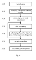
- Fig. 1 is a flow chart of the synchrophasor measurement method according to an embodiment of the present invention
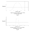
- Figs. 2A and 2B are examples of a band pass filter designed for a first performance class (M class);
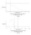
- Figs. 3A and 3B are examples of a band pass filter designed for a second performance class (P class);
- Fig. 4 is a detailed flow chart of the step for updating the estimated system frequency according to an embodiment of the present invention.
- Fig. 5 is a detailed flow chart of the step for second-resampling and synchrophasor calculating according to an embodiment of the present invention
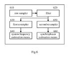
- Fig. 6 is a schematic block diagram of a synchrophasor measurement device according to an embodiment of the present invention.
- Step S105 the synchrophasor measurement method 100 according to the embodiment of the present invention is initialized.
- Step S 110 voltage and current signals in a power system are sampled based on an absolute time reference.
- the voltage and current signals in the power system are sampled in a synchronized sampling system using an A/D converter so as to obtain raw samples of the voltage and current signals.
- the triggering sampling pulse used in the synchronized sampling system is locked in phase with an absolute time reference, such as the 1PPS signal of GPS or other absolute time reference from other sources.
- the triggering sampling pulse used in the synchronized sampling system may be a divided signal of the 1PPS signal of GPS; or a pulse signal generated from local oscillators, and in this case, the local oscillator is synchronized with the absolute time reference at every predetermined interval (for example, 1s).
- the out-of-band interference signal is a signal at frequency f where:
- the reporting rate of PMU may be 10Hz, 20Hz, 60Hz, 120Hz and so on. Taking an example of 10Hz as the reporting rate, then the reporting times per second is 10 times with the corresponding reporting time being at 0.1s, 0.2s, 0.3s,...0.9s, 1s.
- the reporting time may be indicated correspondingly as T 0 , 2T 0 , 3T 0 ,..., kT 0 , (k+1)T 0 ,...,NT 0 .
- Step S130 based on an estimated system frequency, a first resampling is performed on at least one of the voltage and current signals with the out-of-band reference being removed.
- the estimated system frequency is firstly set to the nominal system frequency of the power system.
- Step S140 phasor is calculated for signals obtained from the first resampling, and the estimated system frequency is updated.
- the synchrophasor measurement method 100 returns to Step S130, and performs the first resampling with the estimated system frequency updated at Step S140.
- Step S150 the synchrophasor measurement method 100 according to the embodiment of the present invention advances to Step S150, wherein for each reporting time, the voltage and current signals with the out-of-band reference being removed are second-resampled based on the updated estimated system frequency.
- the system frequency at the reporting time is first estimated based on the updated estimated system frequency, then the voltage and current signals with the out-of-band reference being removed are second-resampled based on the estimated system frequency at the reporting time.
- Step S160 synchrophasor is calculated for the voltage and current signals obtained from the second resampling.
- Step S120 for removing the out-of-band reference signal in the synchrophasor measurement method 100 according to the embodiment of the present invention will be briefly illustrated by referring to Figs. 2 and 3 . It should be understood that the operation of Step S120 for removing the out-of-band reference signal in the synchrophasor measurement method 100 according to the embodiment of the present invention is not limited to the examples described as follows, and a person skilled in the art may design different filters upon actual requirements.
- the out-of-band interference signal is a signal at frequency f where:
- the filters may be designed with considerations to specified sampling rate, reporting rate, nominal system frequency of the power system and performance class.
- performance class there are typically two different kinds in the synchrophasor measurement, namely a first performance class (M class) intended for high precision synchrophasor measurement, and a second performance class (P class) intended for fast response synchrophasor measurement.
- M class first performance class
- P class second performance class
- the M class filter requires a higher measurement precision and is more tolerant of reporting latency
- the P class filter requires a faster response (i.e. a shorter reporting latency) and lower measurement precision.
- a finite impulse response (FIR) filter with the amplitude-frequency response curve as shown in Fig. 2A may be used.
- a FIR filter with the amplitude-frequency response curve as shown in Fig. 2B may be used.
- P class is intended for applications requiring fast response and allowing short reporting latency. Therefore, there is no requirement for P class to remove all out-of-band interference.
- a filter with the amplitude-frequency response curve as shown in Fig. 3A may be used and it meets the requirement of P class application for very small reporting latency. Compared with the amplitude-frequency response curve of Fig. 2A , a shorter reporting latency is obtained in the curve of Fig. 3A at the cost of the flatness of the curve of Fig. 3A being dramatically reduced. In the case where the reporting rate is less than 60Hz, a filter with an amplitude-frequency response similar to that of Fig. 3A may also be used.
- a filter with the amplitude-frequency response curve as shown in Fig. 3B may be used and it meets the requirement of P class application for very small reporting latency.
- Fig. 3B shows an extreme case of the bandpass filter i.e. a low-pass filter.
- a filter with an amplitude-frequency response similar to that of Fig. 3B may also be used.
- x ( ⁇ ) is the filtered voltage and current signals
- h ( ⁇ ) is the coefficients of the filter
- y ( ⁇ ) is raw samples of the voltage and current signals
- L is the number of samples used in the filter.
- Step S140 of the synchrophasor measurement method 100 is not limited to the examples described as follows, and a person skilled in the art may design different calculation window.
- different window length is selected based on the operating state of the power system, i.e. whether the power system is in a steady state or a dynamic state. For example, if the power system is in a steady state, then one cycle window length may be selected for either M class or P class; while if the power system is in a dynamic state, then 1/2 or 1/4 cycle or other proper value may be selected for use as the window length.
- ⁇ ( i ) is the current voltage phasor of one-phase
- N is the number of samples in one cycle
- i is the index number of the current voltage obtained from the first resampling.
- the current obtained from the first resampling and N previous currents obtained from the first resampling may be used to calculate the phasor of the one-phase-current, by using formula (2).
- the current obtained from the first resampling and (N/2) previous current samples obtained from the first resampling may be used to calculate the phasor of the one-phase-current, by using formula (3).
- the one-phase voltage phasor is calculated by using the following formula with the current voltage obtained from the first resampling and (N/4) previous voltage samples obtained from the first resampling and N being equal to 80, i.e. 80 samples per cycle:
- X R ( i ) is the real part of the one-phase current voltage and X I ( i ) is the imaginary part of the one-phase current voltage.
- the current obtained from the first resampling and (N/4) previous current samples obtained from the first resampling may be used to calculate the phasor of the one-phase-current, by using formula (4).
- the estimated system frequency is calculated. For example, the estimated system frequency is updated according to the angle difference between the current estimated phasor and the previous phasor being spaced a predetermined time interval from the current instant.
- V ⁇ 1 i 1 3 ⁇ V ⁇ A i + ⁇ ⁇ V ⁇ B i + ⁇ 2 ⁇ V ⁇ C i
- V ⁇ A i V AR i + j ⁇ V AI i
- V ⁇ B i V BR i + j ⁇ V BI i
- V ⁇ A ( i ) is the A-phase voltage phasor
- V AR ( i ) is the real part of the A-phase voltage phasor
- V AI ( i ) is the imaginary part of the A-phase voltage phasor
- V ⁇ B ( i ) is the B-phase voltage phasor
- V BR ( i ) is the real part of the B-phase voltage phasor
- V BI ( i ) is the imaginary part of the B-phase voltage phasor
- V ⁇ C ( i ) is the C-phase voltage phasor
- V CR ( i ) is the real part of the C-phase voltage phasor
- V CI ( i ) is the imaginary part of the C-phase voltage phasor.
- the positive sequence current phasor may be calculated by using formula (5).
- the estimated system frequency is calculated by using formula (6) according to the angle difference between the positive sequence voltage phasor at the current sample time and the positive sequence voltage phasor at a sample time that is spaced the calculation window length from the current sample time.
- f k is the estimated system frequency at the current time (k)
- f k -1 is the estimated system frequency at the previous time (k-1) before the current time (k)
- ⁇ k ⁇ k - ⁇ k-m is the angle difference of the positive sequence voltage phasor of the current time (k) and the positive sequence voltage phasor of the time (k-m) that is spaced calculation window of m from the current time
- m is the calculation window length represented by the number of samples, i.e.
- the present invention is not limited thereto and the length of the calculation window may be selected according to the requirements and the corresponding m may be obtained.
- Im(•) represents the imaginary part of "•”
- Re(•) represents the real part of "•”.
- the estimated system frequency may be calculated by using formulas (6) and (7) according to the angle difference of the positive sequence voltage phasor of the current time and that of the time spaced the calculation window length from the current time.
- the present invention is not limited thereto, a person skilled in the art may also use other method to calculate estimated system frequency as the updated estimated system frequency where the positive sequence voltage phasor or the positive sequence current phasor is not calculated.
- the estimated system frequency is updated by performing smooth filtering on the calculated estimated system frequency f k .
- f k ⁇ is the estimated system frequency after the smooth filtering, and is used as the updated estimated system frequency.
- smooth filtering is not limited to the case expressed in formula (8), a person skilled in the art may perform smooth filtering upon actual requirements with the weighted average.
- the smooth filtering may not be necessary, in other words, the estimated system frequency calculated with formula (6) may be used directly as the updated estimated system frequency.
- Step S430 after the updated estimated system frequency (formula (6)) is obtained, a time tag corresponding to the system frequency is calculated, wherein the time tag compensates the delay introduced by the out-of-band interference removing. Furthermore, in the case where the smooth filtering is performed (the case of formula (8)), the time tag also compensates the delay introduced by the smooth filtering.
- t t res - t fd - t ad
- t is the time tag of the updated estimated system frequency
- t res is the time in the raw samples of voltage/current signal corresponding to the sample obtained at the current time k from the first resampling
- t fd is the delay introduced by the out-of-band interference removing
- t ad is the delay introduced by the smooth filtering.
- Step S150 of the synchrophasor measurement method 100 will be described by referring to Fig. 5 , wherein for a specific reporting time, the system frequency at the specific reporting time is estimated based on the updated estimated system frequency at Step S140, then the voltage and current signals with the out-of-band interference being removed is second-resampled.
- the operation of the phasor calculation Step S150 in the synchrophasor measurement method 100 according to the embodiment of the present invention is not limited to the examples described as follows, a person skilled in the art may design different calculation windows upon actual requirements.
- the system frequency of each reporting time should be estimated based on the updated estimated system frequency and its corresponding time tag.
- the system frequency at the reporting time is estimated based on the updated estimated system frequency and its corresponding time tag.
- the system frequency at the reporting time can be obtained by the following two steps: obtaining two estimated system frequencies with the time tag being closest to the reporting time, and interpolating between the two estimated system frequencies based on the time tags of the two estimated system frequencies.
- t c is the reporting time
- f out is the system frequency at reporting time
- t m is the closest time tag before the reporting time
- t m +1 is the closest time tag after the reporting time
- f' m is the estimated system frequency with the time tag t m
- f' m +1 is the estimated system frequency with the time tag t m +1 .
- Steps S520-S540 the voltage and current signals with the out-of-band interference being removed are second-resampled.
- the center of a second calculation window is determined based on the reporting time.
- the reporting time may be the center of the second calculation window.
- the length of the second calculation window may be determined based on the reporting rate. For example, when the reporting rate is 60Hz, the length of the second calculation window may be selected as one cycle, i.e. having N samples. However, the present invention is not limited thereto, and with a higher reporting rate such as 120Hz, the length of the second calculation window may be selected as 1/2 cycle, i.e. having N/2 samples.
- Step S540 in the second calculation window, the voltage and current signals with the out-of-band interference being removed are second-resampled based on the estimated system frequency at the reporting time.
- N is the number of samples in one cycle.
- t pi is the corresponding time in the raw samples of voltage and current signals for the i th (1 ⁇ i ⁇ N) sample in the second calculation window;
- t c is the center of the second calculation window i.e. the reporting time of the current calculation;
- t fd is the delay introduced by the out-of-band removing;
- t wid is the half-window delay, i.e. half of the total time length of the second calculation window.
- the synchrophasor measurement method advances to Step S160 as shown in Fig. 1 , wherein in the second calculation window, a synchrophasor is calculated for the voltage and current signals obtained from the second resampling.
- a synchrophasor is calculated for the voltage and current signals obtained from the second resampling, so as to be used as the reporting synchrophasor at the reporting time corresponding to the second calculation window.
- ⁇ out ( i ) is the one-phase current voltage or current
- N is the number of samples in one cycle
- k is the index number of the current voltage or current obtained from the second resampling
- i corresponds to the index number of reporting time.
- a high-precision rate of change of frequency may be obtained after Step S140 wherein the estimated system frequency is updated by the synchrophasor measurement method according to the embodiments of the present invention, wherein the updated estimated system frequency may be the calculation result from formula (8).
- a curve fitting within a predetermined period may be used and the predetermined period may be selected as two continuous cycles.
- the present invention is not limited thereto, and the predetermined period may be selected as other length upon actual system design requirements.
- k f is the slope of the curve fitting i.e. ROCOF; t is the specific time within the predetermined period, f is the estimated system frequency corresponding to the specific time within the predetermined period; and f ini is a constant.
- the amplitude deviation due to filtering can be compensated after Step S160 where the synchrophasor is calculated for the voltage and current signals obtained from the second resampling by the synchrophasor measurement method according to the embodiments of the present invention.
- such amplitude deviation may result from the unflatness of the passband and most of the edge of a bandpass filter.
- ⁇ out ( f out ) is the sychrophasor at frequency f out that is calculated at the reporting time
- ⁇ ' out ( f out ) is the synchrophasor at the frequency f out after compensation
- h ( f out ) is the reciprocal of amplitude coefficient of the designed filter at the frequency f out .
- a synchrophasor measurement device 600 according to an embodiment of the present invention will be briefly described by referring to Fig. 6 .
- the synchrophasor measurement device 600 comprises a raw sampler 610, a filter 620, a first resampler 630, a system frequency estimation means 640, a second resampler 650 and a synchrophasor estimation means 660.
- the raw sampler 610 samples the voltage and current signals of the power system based on an absolute time reference.
- the filter 620 filters the out-of-band interference of the sampled voltage and current signals.
- the filter 620 may be customized according to performance class, nominal system frequency of the power system and reporting rate, and the filter 620 may be a bandpass filter.
- the first resampler 630 first-resamples at least one of the voltage and current signals with the out-of-band interference being removed.
- the system frequency estimation means 640 calculates phasor for signals obtained from the first resampling and updates the estimated system frequency.
- the system frequency estimation means 640 determines the length of the calculation window according to the operation status of the power system, calculates phasor for signals obtained from the first resampling in the calculation window, and updates the estimated system frequency according to the calculated phasor.
- the system frequency estimation means 640 calculates the estimated system frequency for each sample obtained from the first resampling in order to update the estimated system frequency, and sets corresponding time tag for the updated estimated system frequency, the time tag compensating the delay introduced by filtering the out-of-band interference.
- the system frequency estimation means 640 calculates the estimated system frequency for each sample obtained from the first resampling, it also performs smooth filtering on the calculated estimated system frequency so as to update the estimated system frequency.
- the corresponding time tag set for the updated estimated system frequency also compensates the delay introduced by the smooth filtering.
- the second resampler 650 second-resamples the voltage and current signals with the out-of-band interference being removed based on the updated estimated system frequency for a reporting time.
- the second resampler 650 estimates the system frequency at the reporting time based on updated estimated system frequency and its corresponding time tag, determines the center of the second calculation window based on the reporting time, determines the length of the second calculation window based on the reporting rate, and in the second calculation window second-resamples the voltage and current signals with the out-of-band interference being removed based on the estimated system frequency at the reporting time.
- the synchrophasor estimation means 660 calculates the synchrophasor for the voltage and current signals obtained from the second resampling.
- the raw sampler 610, the first resampler 630 and the second resampler 650 can be implemented individually in hardware samplers, or the raw sampler 610 may be implemented in a hardware A/D sampler, while the first resampler 630 and the second resampler 650 may be implemented in special purposed processor, general purposed processor or FGPA etc.
- the filter 620 may be implemented in special purposed filter circuits, or in special purposed processor, general purposed processor or FGPA etc.
- the system frequency estimation means 640 and the synchrophasor estimation means 660 may be implemented individually in separate special purposed processors, or may be implemented on the same general purposed processor or FGPA etc.
- the raw samples of voltage and current signals are first filtered to remove the out-of-band interference, then specific calculation window length is selected for each sample in the first resampling according to the operation status of the power system to obtain the estimated system frequency, and the synchronized voltage phasor and synchronized current phasor at the reporting time are obtained with the second resampling, thus it is guaranteed to be not only applicable to the steady state of the power system but also the dynamic state thereof, and at the same time, high-precision synchrophasor measurement result is provided.
Landscapes
- Engineering & Computer Science (AREA)
- Power Engineering (AREA)
- Physics & Mathematics (AREA)
- General Physics & Mathematics (AREA)
- Measuring Frequencies, Analyzing Spectra (AREA)
- Measurement Of Current Or Voltage (AREA)
Abstract
Description
- The present invention relates to power system automatic measurement, and more specifically to a high-precision system frequency measurement method, synchrophasor measurement method and device thereof.
- Synchronized phasor (synchrophasor) measurement unit (PMU) has become an important measurement component in a power system and can provide high precision voltage and current phasors and frequency which are synchronized with an absolute time reference. The applications of PMU have been well recognized for real time dynamic monitoring, operation and control of the power system.
- Traditionally, a power system may be monitored through a combination of non-synchronized measurements, for example, generator/load power and voltage magnitudes are fed into a software model, and then the complete voltage angle and magnitude information for each bus for specified load and generator real power and voltage conditions are calculated. However, these quantities can be calculated directly using PMU.
- With the growing demand for synchrophasor measurement technology, a standard related to this measurement has been set up by IEEE to ensure the interoperability of devices from different vendors since 2005. There are now many PMUs in compliance with the standard in the market. However, as the standard is only designed for steady-state measurement and cannot meet further demand for dynamic-state measurement (such as during power swing, phase angle change, frequency consecutive change and even fault disturbance) with a lack of comparability and interoperability among synchrophasors measured by different products, some vendors have begun to use their enterprise standard defined by themselves. Based on the new demand, the IEEE and IEC have been working together to establish a new standard including dynamic-state measurement. This standard may be released soon.
- A synchrophasor measurement method and device applicable to both the steady-state measurement and dynamic-state measurement in a power system is thus needed. Such a method and device is able to comply with the new standard that covers the dynamic-state measurement in the power system.
- In consideration of the above issues, the present invention is proposed. It aims at providing a high precision synchrophasor measurement method and device, which obtains synchronized voltage phasor and synchronized current phasor by removing the out-of-band interference from raw samples of voltage and current signals, then a first resampling to obtain an estimated system frequency followed by a second resampling for each reporting time. The synchrophasor measurement method selects different calculation window length for steady operation and dynamic operation of the power system respectively, and calculates the estimated system frequency for each sample, thus high-precision may still be achieved while the method is applied to the dynamic operating condition and the requirements of the new standard may be met.
- According to one aspect of the present invention, it is provided a synchrophasor measurement method, comprising: sampling voltage and current signals in a power system based on an absolute time reference; removing out-of-band interference in the sampled voltage and current signals; first-resampling at least one of the voltage and current signals with the out-of-band reference being removed based on an estimated system frequency; calculating phasor for signals obtained from the first resampling, and updating the estimated system frequency; for a reporting time, second-resampling the voltage and current signals with the out-of-band reference being removed based on the updated estimated system frequency; and calculating synchrophasor for the voltage and current signals obtained from the second resampling.
- Preferably, in the synchrophasor measurement method, the out-of-band interference in the sampled voltage and current signals is removed with a bandpass filter which is customized according to performance class, nominal system frequency of the power system and reporting rate.
- Preferably, in the synchrophasor measurement method, calculating phasor for signals obtained from the first resampling comprises: determining the length of a first calculation window according to an operation status of the power system; and calculating phasor for signals obtained from the first resampling in the first calculation window.
- Preferably, in the synchrophasor measurement method, updating the estimated system frequency comprises: for each sample obtained from the first resampling, calculating the estimated system frequency; smooth filtering the calculated estimated system frequency to update the estimated system frequency; and setting a corresponding time tag for the updated estimated system frequency, said the time tag compensating the delay introduced by the out-of-band interference removing and the delay introduced by the smooth filtering.
- Preferably, in the synchrophasor measurement method, second-resampling the voltage and current signals with the out-of-band reference being removed comprises: estimating the system frequency at a reporting time based on the updated estimated system frequency and its corresponding time tag; and seond-resampling the voltage and current signals with the out-of-band interference being removed based on the estimated system frequency at the reporting time, which comprises: determining the center of a second calculation window based on the reporting time; determining the length of the second calculation window based on a reporting rate, and second-resampling the voltage and current signals with the out-of-band interference being removed based on the estimated system frequency at the reporting time in the second calculation window.
- Preferably, the synchrophasor measurement method further comprises calculating rate of change of system frequency by using curve fitting based on the updated estimated system frequency.
- According to another aspect of the present invention, it is provided a synchrophasor measurement device, comprising: a raw sampler, for sampling voltage and current signals in a power system based on an absolute time reference; a filter, for removing out-of-band interference in the sampled voltage and current signals; a first resampler, for first-resampling at least one of the voltage and current signals with the out-of-band reference being removed based on an estimated system frequency; a system frequency estimation means, for calculating phasor for signals obtained from the first resampling, and updating the estimated system frequency; a second resampler, for second-resampling the voltage and current signals with the out-of-band reference being removed based on the updated estimated system frequency for a reporting time; and a synchrophasor estimation means, for calculating synchrophasor for the voltage and current signals obtained from the second resampling.
- Preferably, said filter is a bandpass filter being customized according to performance class, nominal system frequency of the power system and reporting rate.
- Preferably, the system frequency estimation means determines the length of a first calculation window according to an operation status of the power system, and calculates phasor for signals obtained from the first resampling in the first calculation window.
- Preferably, the system frequency estimation means calculates the estimated system frequency for each sample obtained from the first resampling, smooth filters the calculated estimated system frequency to update the estimated system frequency, and sets a corresponding time tag for the updated estimated system frequency, said time tag compensating the delay introduced by the out-of-band interference removing and the delay introduced by the smooth filtering.
- Preferably, the second resampler estimates the system frequency at a reporting time based on the updated estimated system frequency and its corresponding time tag, determines the center of a second calculation window based on the reporting time, determines the length of the second calculation window based on a reporting rate, and secondly resamples the voltage and current signals with the out-of-band interference being removed based on the estimated system frequency at the reporting time in the second calculation window.
- According to still another aspect of the present invention, it is provided a system frequency measurement method of a power system, comprising: sampling voltage and current signals in a power system based on an absolute time reference; removing out-of-band interference in the sampled voltage and current signals; first-resampling at least one of the voltage and current signals with the out-of-band reference being removed based on an estimated system frequency; and calculating phasor for signals obtained from the first resampling, and updating the estimated system frequency.
- Preferably, in the system frequency measurement method, calculating phasor for signals obtained from the first resampling comprises: determining the length of a first calculation window according to an operation status of the power system; and calculating phasor for signals obtained from the first resampling in the first calculation window.
- Preferably, in the system frequency measurement method, updating the estimated system frequency comprises: for each sample obtained from the first resampling, calculating the estimated system frequency; smooth filtering the calculated estimated system frequency to update the estimated system frequency; and setting a corresponding time tag for the updated estimated system frequency, said time tag compensating the delay introduced by the out-of-band interference removing and the delay introduced by the smooth filtering.
- Preferably, the system frequency measurement method further comprises: for a reporting time, estimating the system frequency at the reporting time based on the updated estimated system frequency and its corresponding time tag; second-resampling the voltage and current signals with the out-of-band reference being removed based on the estimated system frequency at the reporting time; and calculating synchrophasor for the voltage and current signals obtained from the second resampling.
- Preferably, in the system frequency measurement method, second resampling the voltage and current signals with the out-of-band interference being removed comprises: determining the center of a second calculation window based on the reporting time; determining the length of the second calculation window based on a reporting rate, and second-resampling the voltage and current signals with the out-of-band interference being removed based on the estimated system frequency at the reporting time in the second calculation window, wherein, calculating synchrophasor for voltage and current signals obtained from the second resampling comprises: calculating synchrophasor for the voltage and current signals obtained from the second resampling in the second calculation window.
- Preferably, the system frequency measurement method further comprises: calculating rate of change of system frequency by using curve fitting based on the updated estimated system frequency.
- With the synchrophasor measurement method and device according to the present invention, the raw samples of voltage and current signals are first filtered to remove the out-of-band interference, then a specific calculation window length is selected for each sample in the first resampling according to the operation status of the power system to obtain the estimated system frequency, and the synchronized voltage phasor and synchronized current phasor at the reporting time are obtained with the second resampling, thus it is guaranteed to be not only applicable to the steady state of the power system but also the dynamic state thereof, and at the same time, high-precision synchrophasor measurement result is provided.
- The above and other purposes, characteristics and advantages of the present invention will become more apparent to those skilled in the art with the detailed description to the embodiments of the present invention by referring to the accompanying drawings, in which:
-
Fig. 1 is a flow chart of the synchrophasor measurement method according to an embodiment of the present invention; -
Figs. 2A and 2B are examples of a band pass filter designed for a first performance class (M class); -
Figs. 3A and 3B are examples of a band pass filter designed for a second performance class (P class); -
Fig. 4 is a detailed flow chart of the step for updating the estimated system frequency according to an embodiment of the present invention; -
Fig. 5 is a detailed flow chart of the step for second-resampling and synchrophasor calculating according to an embodiment of the present invention; -
Fig. 6 is a schematic block diagram of a synchrophasor measurement device according to an embodiment of the present invention. - A synchrophasor measurement method and device according to embodiments of the present invention will now be described by referring to the accompanying figures.
- First, a synchrophasor measurement method according to an embodiment of the present invention will be described by referring to
Figure 1 . - At Step S105, the
synchrophasor measurement method 100 according to the embodiment of the present invention is initialized. - At
Step S 110, voltage and current signals in a power system are sampled based on an absolute time reference. As known in the art, the voltage and current signals in the power system are sampled in a synchronized sampling system using an A/D converter so as to obtain raw samples of the voltage and current signals. Typically, the triggering sampling pulse used in the synchronized sampling system is locked in phase with an absolute time reference, such as the 1PPS signal of GPS or other absolute time reference from other sources. For example, the triggering sampling pulse used in the synchronized sampling system may be a divided signal of the 1PPS signal of GPS; or a pulse signal generated from local oscillators, and in this case, the local oscillator is synchronized with the absolute time reference at every predetermined interval (for example, 1s). - Then at Step S120, the out-of-band interference is removed from the raw samples of the voltage and current signals. The out-of-band interference signal is a signal at frequency f where: |f-f0|≥Fs/2, wherein f0 is the nominal system frequency of the power system; and Fs is the reporting rate of PMU (synchronized phasor measurement unit), i.e. the reporting times per second. For example, the reporting rate of PMU may be 10Hz, 20Hz, 60Hz, 120Hz and so on. Taking an example of 10Hz as the reporting rate, then the reporting times per second is 10 times with the corresponding reporting time being at 0.1s, 0.2s, 0.3s,...0.9s, 1s. More generally, when the reporting interval is labeled as T0, the reporting time may be indicated correspondingly as T0, 2T0, 3T0,..., kT0, (k+1)T0,...,NT0.
- At Step S130, based on an estimated system frequency, a first resampling is performed on at least one of the voltage and current signals with the out-of-band reference being removed. After the initialization of the system, the estimated system frequency is firstly set to the nominal system frequency of the power system.
- Then, at Step S140, phasor is calculated for signals obtained from the first resampling, and the estimated system frequency is updated.
- Next, the
synchrophasor measurement method 100 according to the embodiment of the present invention returns to Step S130, and performs the first resampling with the estimated system frequency updated at Step S140. - On the other hand, after Step S140, the
synchrophasor measurement method 100 according to the embodiment of the present invention advances to Step S150, wherein for each reporting time, the voltage and current signals with the out-of-band reference being removed are second-resampled based on the updated estimated system frequency. For example, at Step S150, for each reporting time, the system frequency at the reporting time is first estimated based on the updated estimated system frequency, then the voltage and current signals with the out-of-band reference being removed are second-resampled based on the estimated system frequency at the reporting time. - At last, at Step S160, synchrophasor is calculated for the voltage and current signals obtained from the second resampling.
- Next, exemplary operation of Step S120 for removing the out-of-band reference signal in the
synchrophasor measurement method 100 according to the embodiment of the present invention will be briefly illustrated by referring toFigs. 2 and3 . It should be understood that the operation of Step S120 for removing the out-of-band reference signal in thesynchrophasor measurement method 100 according to the embodiment of the present invention is not limited to the examples described as follows, and a person skilled in the art may design different filters upon actual requirements. - As described above, the out-of-band interference signal is a signal at frequency f where: |f-f0l≥Fs/2, wherein f0 is the nominal system frequency of the power system; and Fs is the reporting rate of PMU, i.e. the reporting times per second.
- The filters may be designed with considerations to specified sampling rate, reporting rate, nominal system frequency of the power system and performance class. Regarding the performance class, there are typically two different kinds in the synchrophasor measurement, namely a first performance class (M class) intended for high precision synchrophasor measurement, and a second performance class (P class) intended for fast response synchrophasor measurement. The M class filter requires a higher measurement precision and is more tolerant of reporting latency, while the P class filter requires a faster response (i.e. a shorter reporting latency) and lower measurement precision.
- For example, for a M class filter, when the sampling rate is 4800Hz, the reporting rate is 60Hz and the nominal system frequency is 60Hz, a finite impulse response (FIR) filter with the amplitude-frequency response curve as shown in
Fig. 2A may be used. - As an alternative example, for a M class filter, when the sampling rate is 4800Hz, the reporting rate is 20Hz and the nominal system frequency is 60Hz, a FIR filter with the amplitude-frequency response curve as shown in
Fig. 2B may be used. - As it is considered that P class is intended for applications requiring fast response and allowing short reporting latency. Therefore, there is no requirement for P class to remove all out-of-band interference.
- For example, for a P class filter, when the sampling rate is 4800Hz, the reporting rate is 60 Hz and the nominal system frequency is 60Hz, a filter with the amplitude-frequency response curve as shown in
Fig. 3A may be used and it meets the requirement of P class application for very small reporting latency. Compared with the amplitude-frequency response curve ofFig. 2A , a shorter reporting latency is obtained in the curve ofFig. 3A at the cost of the flatness of the curve ofFig. 3A being dramatically reduced. In the case where the reporting rate is less than 60Hz, a filter with an amplitude-frequency response similar to that ofFig. 3A may also be used. - As an alternative example, for a P class filter, when the sampling rate is 4800Hz, the reporting rate is 120Hz and the nominal system frequency is 60Hz, a filter with the amplitude-frequency response curve as shown in
Fig. 3B may be used and it meets the requirement of P class application for very small reporting latency.Fig. 3B shows an extreme case of the bandpass filter i.e. a low-pass filter. Furthermore, in the case where the reporting rate is larger than 60Hz, a filter with an amplitude-frequency response similar to that ofFig. 3B may also be used. - After the filter having been designed, the filtered signals may be obtained as follows:

- Wherein x(·) is the filtered voltage and current signals; h(·) is the coefficients of the filter; y(·) is raw samples of the voltage and current signals; and L is the number of samples used in the filter.
- Next, the exemplary operation of Step S140 of the
synchrophasor measurement method 100 according to an embodiment of the present invention will be described. It should be understood that the operation of Step S140 of thesynchrophasor measurement method 100 according to the embodiment of the present invention is not limited to the examples described as follows, and a person skilled in the art may design different calculation window. - At Step S140, different window length is selected based on the operating state of the power system, i.e. whether the power system is in a steady state or a dynamic state. For example, if the power system is in a steady state, then one cycle window length may be selected for either M class or P class; while if the power system is in a dynamic state, then 1/2 or 1/4 cycle or other proper value may be selected for use as the window length.
- For the steady state, the one-phase voltage phasor is calculated by using the following formula with a current voltage obtained from the first resampling and N previous voltages obtained from the first resampling:

- Wherein Ẋ(i) is the current voltage phasor of one-phase, N is the number of samples in one cycle and i is the index number of the current voltage obtained from the first resampling.
- Similarly, the current obtained from the first resampling and N previous currents obtained from the first resampling may be used to calculate the phasor of the one-phase-current, by using formula (2).
- For the dynamic state, when the calculation window length is selected to be 1/2 cycle, the one-phase voltage phasor may be calculated by using the following formula with the current voltage obtained from the first resampling and (N/2) previous voltage samples obtained from the first resampling:

- Similarly, the current obtained from the first resampling and (N/2) previous current samples obtained from the first resampling may be used to calculate the phasor of the one-phase-current, by using formula (3).
- For the dynamic state, when the calculation window length is selected to be 1/4 cycle, the one-phase voltage phasor is calculated by using the following formula with the current voltage obtained from the first resampling and (N/4) previous voltage samples obtained from the first resampling and N being equal to 80, i.e. 80 samples per cycle:

- Wherein XR (i) is the real part of the one-phase current voltage and XI (i) is the imaginary part of the one-phase current voltage.
- Similarly, the current obtained from the first resampling and (N/4) previous current samples obtained from the first resampling may be used to calculate the phasor of the one-phase-current, by using formula (4).
- It should be understood that the above formulas (2), (3) and (4) are examples only and the present invention are not limited thereto, and alternatively formulas (2), (3) and (4) may be achieved with recursion.
- Next, it will be described as how to update the estimated system frequency with the calculated phasor resulted from the above formulas by referring to
Fig. 4 . - At Step S140, for each sample obtained from the first resampling, the estimated system frequency is calculated. For example, the estimated system frequency is updated according to the angle difference between the current estimated phasor and the previous phasor being spaced a predetermined time interval from the current instant.
- For example, after an one-phase voltage phasor (i.e. un-synchronized voltage phasor) is obtained, the positive sequence voltage phasor is given by:

- Wherein


- Wherein V̇A (i) is the A-phase voltage phasor, VAR (i)is the real part of the A-phase voltage phasor, VAI (i) is the imaginary part of the A-phase voltage phasor; V̇B (i) is the B-phase voltage phasor, VBR (i) is the real part of the B-phase voltage phasor, VBI (i) is the imaginary part of the B-phase voltage phasor; V̇C (i) is the C-phase voltage phasor, VCR (i)is the real part of the C-phase voltage phasor, VCI (i) is the imaginary part of the C-phase voltage phasor.
- Similarly, after an one-phase current phasor is obtained, the positive sequence current phasor may be calculated by using formula (5).
- After the current positive sequence voltage phasor for each sample obtained from the first resampling is calculated, the estimated system frequency is calculated by using formula (6) according to the angle difference between the positive sequence voltage phasor at the current sample time and the positive sequence voltage phasor at a sample time that is spaced the calculation window length from the current sample time.

- Wherein fk is the estimated system frequency at the current time (k), f k-1 is the estimated system frequency at the previous time (k-1) before the current time (k), Δφ k = φ k - φ k-m is the angle difference of the positive sequence voltage phasor of the current time (k) and the positive sequence voltage phasor of the time (k-m) that is spaced calculation window of m from the current time, m is the calculation window length represented by the number of samples, i.e. the number of samples in the calculation window, for example taking N (one cycle)=80, for the case where the calculation window is selected to be one cycle, m=80; for the case where the calculation window is selected to be 1/2 cycle, m=40; and for the case where the calculation window is selected to be 1/4 cycle, m=20. However, the present invention is not limited thereto and the length of the calculation window may be selected according to the requirements and the corresponding m may be obtained.
- Δφ k may be calculated by using the following formula:


Wherein Im(•) represents the imaginary part of "•", and Re(•) represents the real part of "•". - Similarly, the estimated system frequency may be calculated by using formulas (6) and (7) according to the angle difference of the positive sequence voltage phasor of the current time and that of the time spaced the calculation window length from the current time.
- However, the present invention is not limited thereto, a person skilled in the art may also use other method to calculate estimated system frequency as the updated estimated system frequency where the positive sequence voltage phasor or the positive sequence current phasor is not calculated.
- More advantageously, at Step S420, the estimated system frequency is updated by performing smooth filtering on the calculated estimated system frequency fk . For example, the smooth filtering may be performed with the estimated system frequency fk at the current time (k) and previous m estimated system frequencies by using the following formula:

- Wherein

- However, the smooth filtering is not limited to the case expressed in formula (8), a person skilled in the art may perform smooth filtering upon actual requirements with the weighted average.
- Furthermore, the smooth filtering may not be necessary, in other words, the estimated system frequency calculated with formula (6) may be used directly as the updated estimated system frequency.
- Then at Step S430, after the updated estimated system frequency (formula (6)) is obtained, a time tag corresponding to the system frequency is calculated, wherein the time tag compensates the delay introduced by the out-of-band interference removing. Furthermore, in the case where the smooth filtering is performed (the case of formula (8)), the time tag also compensates the delay introduced by the smooth filtering.

- Wherein t is the time tag of the updated estimated system frequency, tres is the time in the raw samples of voltage/current signal corresponding to the sample obtained at the current time k from the first resampling, tfd is the delay introduced by the out-of-band interference removing, and tad is the delay introduced by the smooth filtering.
- In addition, after the updated estimated system frequency is obtained (formula (6) or (8)), the new sample interval (i.e. the interval between the current time and the next sampling time) can be calculated by the following formula:

- Next, an exemplary operation of the Step S150 of the
synchrophasor measurement method 100 according to the embodiment of the present invention will be described by referring toFig. 5 , wherein for a specific reporting time, the system frequency at the specific reporting time is estimated based on the updated estimated system frequency at Step S140, then the voltage and current signals with the out-of-band interference being removed is second-resampled. It should be understood that the operation of the phasor calculation Step S150 in thesynchrophasor measurement method 100 according to the embodiment of the present invention is not limited to the examples described as follows, a person skilled in the art may design different calculation windows upon actual requirements. - As each reporting time does not necessarily correspond to the time tag of the updated estimated system frequency after the first resampling, the system frequency of each reporting time should be estimated based on the updated estimated system frequency and its corresponding time tag.
- First at Step S510, the system frequency at the reporting time is estimated based on the updated estimated system frequency and its corresponding time tag.
- For example, the system frequency at the reporting time can be obtained by the following two steps: obtaining two estimated system frequencies with the time tag being closest to the reporting time, and interpolating between the two estimated system frequencies based on the time tags of the two estimated system frequencies. The system frequency of at the reporting time can be estimated by using the following formula:

- Wherein tc is the reporting time, fout is the system frequency at reporting time, tm is the closest time tag before the reporting time, t m+1 is the closest time tag after the reporting time, f'm is the estimated system frequency with the time tag tm, and f' m+1 is the estimated system frequency with the time tag t m+1.
- Next, in Steps S520-S540, the voltage and current signals with the out-of-band interference being removed are second-resampled.
- Specifically, at Step S520, the center of a second calculation window is determined based on the reporting time. For example, the reporting time may be the center of the second calculation window.
- At Step S530, the length of the second calculation window may be determined based on the reporting rate. For example, when the reporting rate is 60Hz, the length of the second calculation window may be selected as one cycle, i.e. having N samples. However, the present invention is not limited thereto, and with a higher reporting rate such as 120Hz, the length of the second calculation window may be selected as 1/2 cycle, i.e. having N/2 samples.
- Then at Step S540, in the second calculation window, the voltage and current signals with the out-of-band interference being removed are second-resampled based on the estimated system frequency at the reporting time.
- For example, the sample interval of the second resampling can be calculated with the estimated system frequency at the reporting time by using the following formula:

- Wherein N is the number of samples in one cycle.
- Therefore, in the case where the reporting time is the center of the second calculation window, the corresponding time in the raw samples of voltage and current signals for each sample in the second calculation window can be calculated as follows:

- Wherein tpi is the corresponding time in the raw samples of voltage and current signals for the ith (1≤i≤N) sample in the second calculation window; tc is the center of the second calculation window i.e. the reporting time of the current calculation; tfd is the delay introduced by the out-of-band removing; and twid is the half-window delay, i.e. half of the total time length of the second calculation window.
- At last, after all the steps in
Fig. 5 are performed, the synchrophasor measurement method according to the embodiment of the present invention advances to Step S160 as shown inFig. 1 , wherein in the second calculation window, a synchrophasor is calculated for the voltage and current signals obtained from the second resampling. - In the second calculation window, a synchrophasor is calculated for the voltage and current signals obtained from the second resampling, so as to be used as the reporting synchrophasor at the reporting time corresponding to the second calculation window. When the calculation window is one cycle, the calculation formula is given by:

- Wherein Ẋout (i) is the one-phase current voltage or current, N is the number of samples in one cycle, k is the index number of the current voltage or current obtained from the second resampling and i corresponds to the index number of reporting time.
- Furthermore, a high-precision rate of change of frequency (ROCOF) may be obtained after Step S140 wherein the estimated system frequency is updated by the synchrophasor measurement method according to the embodiments of the present invention, wherein the updated estimated system frequency may be the calculation result from formula (8). In order to obtain high-precision, a curve fitting within a predetermined period may be used and the predetermined period may be selected as two continuous cycles. However, the present invention is not limited thereto, and the predetermined period may be selected as other length upon actual system design requirements.

- Wherein kf is the slope of the curve fitting i.e. ROCOF; t is the specific time within the predetermined period, f is the estimated system frequency corresponding to the specific time within the predetermined period; and fini is a constant.
- Furthermore, because the foregoing amplitude-frequency response cannot be completely flat, especially for filters of class P (as can be seen from
Figs. 3A and 3B ), it is necessary to compensate the calculated phasor's amplitude in order to achieve high precision. Accordingly, the amplitude deviation due to filtering can be compensated after Step S160 where the synchrophasor is calculated for the voltage and current signals obtained from the second resampling by the synchrophasor measurement method according to the embodiments of the present invention. For example, such amplitude deviation may result from the unflatness of the passband and most of the edge of a bandpass filter. - Ideally, all designed filter's amplitude response can be pre-calculated off-line and saved in a buffer according to piecewise-defined frequency. Therefore, the amplitude deviation due to unflatness of the passband and most of the edge of a bandpass filter can be calculated using the following formula:

- Where Ẋout (fout ) is the sychrophasor at frequency fout that is calculated at the reporting time; Ẋ'out (fout ) is the synchrophasor at the frequency fout after compensation; and h(fout ) is the reciprocal of amplitude coefficient of the designed filter at the frequency fout.
- Next, a synchrophasor measurement device 600 according to an embodiment of the present invention will be briefly described by referring to
Fig. 6 . - The synchrophasor measurement device 600 comprises a
raw sampler 610, afilter 620, afirst resampler 630, a system frequency estimation means 640, asecond resampler 650 and a synchrophasor estimation means 660. - The
raw sampler 610 samples the voltage and current signals of the power system based on an absolute time reference. - The
filter 620 filters the out-of-band interference of the sampled voltage and current signals. As described above, thefilter 620 may be customized according to performance class, nominal system frequency of the power system and reporting rate, and thefilter 620 may be a bandpass filter. - The
first resampler 630 first-resamples at least one of the voltage and current signals with the out-of-band interference being removed. - The system frequency estimation means 640 calculates phasor for signals obtained from the first resampling and updates the estimated system frequency.
- Preferably, the system frequency estimation means 640 determines the length of the calculation window according to the operation status of the power system, calculates phasor for signals obtained from the first resampling in the calculation window, and updates the estimated system frequency according to the calculated phasor.
- Preferably, the system frequency estimation means 640 calculates the estimated system frequency for each sample obtained from the first resampling in order to update the estimated system frequency, and sets corresponding time tag for the updated estimated system frequency, the time tag compensating the delay introduced by filtering the out-of-band interference.
- More preferably, after the system frequency estimation means 640 calculates the estimated system frequency for each sample obtained from the first resampling, it also performs smooth filtering on the calculated estimated system frequency so as to update the estimated system frequency. In this case, the corresponding time tag set for the updated estimated system frequency also compensates the delay introduced by the smooth filtering.
- The
second resampler 650 second-resamples the voltage and current signals with the out-of-band interference being removed based on the updated estimated system frequency for a reporting time. - Preferably, the
second resampler 650 estimates the system frequency at the reporting time based on updated estimated system frequency and its corresponding time tag, determines the center of the second calculation window based on the reporting time, determines the length of the second calculation window based on the reporting rate, and in the second calculation window second-resamples the voltage and current signals with the out-of-band interference being removed based on the estimated system frequency at the reporting time. - The synchrophasor estimation means 660 calculates the synchrophasor for the voltage and current signals obtained from the second resampling.
- The
raw sampler 610, thefirst resampler 630 and thesecond resampler 650 can be implemented individually in hardware samplers, or theraw sampler 610 may be implemented in a hardware A/D sampler, while thefirst resampler 630 and thesecond resampler 650 may be implemented in special purposed processor, general purposed processor or FGPA etc. - The
filter 620 may be implemented in special purposed filter circuits, or in special purposed processor, general purposed processor or FGPA etc. - The system frequency estimation means 640 and the synchrophasor estimation means 660 may be implemented individually in separate special purposed processors, or may be implemented on the same general purposed processor or FGPA etc.
- With the synchrophasor measurement method and device according to the present invention, the raw samples of voltage and current signals are first filtered to remove the out-of-band interference, then specific calculation window length is selected for each sample in the first resampling according to the operation status of the power system to obtain the estimated system frequency, and the synchronized voltage phasor and synchronized current phasor at the reporting time are obtained with the second resampling, thus it is guaranteed to be not only applicable to the steady state of the power system but also the dynamic state thereof, and at the same time, high-precision synchrophasor measurement result is provided.
- While exemplary embodiments have been described by referring to the accompanying drawings herein, it should be understood that the above exemplary embodiments are illustrative only and are not intended to limit the scope of the present invention thereto. An ordinary person skilled in the art may make various modifications and alterations without departing from the scope and spirit of the present invention. It is intended that all these modifications and alterations be encompassed within the appended claims.
Claims (15)
- A synchrophasor measurement method, comprising:sampling voltage and current signals in a power system based on an absolute time reference;removing out-of-band interference in the sampled voltage and current signals;first-resampling at least one of the voltage and current signals with the out-of-band interference being removed based on an estimated system frequency;calculating phasor for signals obtained from the first resampling, and updating the estimated system frequency;for a reporting time, second-resampling the voltage and current signals with the out-of-band interference being removed based on the updated estimated system frequency; andcalculating synchrophasor for the voltage and current signals obtained from the second resampling.
- The synchrophasor measurement method according to claim 1, wherein,
the out-of-band interference in the sampled voltage and current signals is removed with a bandpass filter which is customized according to performance class, nominal system frequency of the power system and reporting rate; and/or
calculating phasor for signals obtained from the first resampling comprises:determining the length of a first calculation window according to an operation status of the power system; andcalculating phasor for signals obtained from the first resampling in the first calculation window. - The synchrophasor measurement method according to claim 1, wherein updating the estimated system frequency comprises:for each sample obtained from the first resampling, calculating the estimated system frequency;smooth filtering the calculated estimated system frequency to update the estimated system frequency; andsetting a corresponding time tag for the updated estimated system frequency, the time tag compensating the delay introduced by the out-of-band interference removing and the delay introduced by the smooth filtering.
- The synchrophasor measurement method according to claim 3, wherein calculating the estimated system frequency for each sample obtained from the first resampling comprises:calculating the estimated system frequency according to the angle difference of the phasor between the sample obtained from the first resampling and a previous sample obtained from the first resampling being spaced a predetermined time length from the sample; andwhereinsecond-resampling the voltage and current signals with the out-of-band interference being removed comprises:estimating the system frequency at a reporting time based on the updated estimated system frequency and its corresponding time tag; andsecond-resampling the voltage and current signals with the out-of-band interference being removed based on the estimated system frequency at the reporting time, comprising:determining the center of a second calculation window based on the reporting time;determining the length of the second calculation window based on a reporting rate, andsecond-resampling the voltage and current signals with the out-of-band interference being removed based on the estimated system frequency at the reporting time in the second calculation window,wherein, calculating synchrophasor for the voltage and current signals obtained from the second resampling comprises:calculating synchrophasor for the voltage and current signals obtained from the second resampling in the second calculation window.
- The synchrophasor measurement method according to claim 4, wherein estimating the system frequency at the reporting time comprises:obtaining system frequencies estimated at two times closest to the reporting time; andinterpolating between the system frequencies estimated at the two times closest to the reporting time, in order to calculate the system frequency at the reporting time.
- The synchrophasor measurement method according to claim 1, further comprising:calculating rate of change of system frequency by using curve fitting based on the updated estimated system frequency.
- A synchrophasor measurement device, comprising:a raw sampler, for sampling voltage and current signals in a power system based on an absolute time reference;a filter, for removing out-of-band interference in the sampled voltage and current signals;a first resampler, for first-resampling at least one of the voltage and current signals with the out-of-band interference being removed based on an estimated system frequency;a system frequency estimation means, for calculating phasor for signals obtained from the first resampling, and updating the estimated system frequency;a second resampler, for second-resampling the voltage and current signals with the out-of-band interference being removed based on the updated estimated system frequency for a reporting time; anda synchrophasor estimation means, for calculating synchrophasor for the voltage and current signals obtained from the second resampling.
- The synchrophasor measurement device according to claim 7, wherein,
said filter is a bandpass filter being customized according to performance class, nominal system frequency of the power system and reporting rate; and/or
the system frequency estimation means determines the length of a first calculation window according to an operation status of the power system, and calculates phasor for signals obtained from the first resampling in the first calculation window. - The synchrophasor measurement device according to claim 7, wherein the system frequency estimation means calculates the estimated system frequency for each sample obtained from the first resampling, smooth filters the calculated estimated system frequency to update the estimated system frequency, and sets a corresponding time tag for the updated estimated system frequency, the time tag compensating the delay introduced by the out-of-band interference removing and the delay introduced by the smooth filtering.
- The synchrophasor measurement device according to claim 9, wherein the second resampler estimates the system frequency at a reporting time based on the updated estimated system frequency and its corresponding time tag, determines the center of a second calculation window based on the reporting time, determines the length of the second calculation window based on a reporting rate, and second-resamples the voltage and current signals with the out-of-band interference being removed based on the estimated system frequency at the reporting time in the second calculation window.
- A system frequency measurement method of a power system, comprising:sampling voltage and current signals in a power system based on an absolute time reference;removing out-of-band interference in the sampled voltage and current signals;first-resampling at least one of the voltage and current signals with the out-of-band interference being removed based on an estimated system frequency; andcalculating phasor for signals obtained from the first resampling, and updating the estimated system frequency.
- The system frequency measurement method according to claim 11, wherein calculating phasor for signals obtained from the first resampling comprises:determining the length of a first calculation window according to an operation status of the power system; andcalculating phasor for signals obtained from the first resampling in the first calculation window; andwherein updating the estimated system frequency comprises:for each sample obtained from the first resampling, calculating the estimated system frequency;smooth filtering the calculated estimated system frequency to update the estimated system frequency; andsetting a corresponding time tag for the updated estimated system frequency, the time tag compensating the delay introduced by the out-of-band interference removing and the delay introduced by the smooth filtering.
- The system frequency measurement method according to claim 12, further comprising:for a reporting time, estimating the system frequency at the reporting time based on the updated estimated system frequency and its corresponding time tag;second-resampling the voltage and current signals with the out-of-band interference being removed based on the estimated system frequency at the reporting time; andcalculating synchrophasor for the voltage and current signals obtained from the second resampling.
- The system frequency measurement method according to claim 13, wherein second-resampling the voltage and current signals with the out-of-band interference being removed comprises:determining the center of a second calculation window based on the reporting time;determining the length of the second calculation window based on a reporting rate, andsecond-resampling the voltage and current signals with the out-of-band interference being removed based on the estimated system frequency at the reporting time in the second calculation window,
wherein, calculating synchrophasor for the voltage and current signals obtained from the second resampling comprises:calculating synchrophasor for the voltage and current signals obtained from the second resampling in the second calculation window. - The system frequency measurement method according to claim 11, further comprising:calculating rate of change of system frequency by using curve fitting based on the updated estimated system frequency.
Applications Claiming Priority (1)
| Application Number | Priority Date | Filing Date | Title |
|---|---|---|---|
| CN201210262698.5A CN103575980B (en) | 2012-07-26 | 2012-07-26 | System frequency measuring method, synchronous phasor measuring method and equipment |
Publications (2)
| Publication Number | Publication Date |
|---|---|
| EP2690451A1 true EP2690451A1 (en) | 2014-01-29 |
| EP2690451B1 EP2690451B1 (en) | 2018-12-19 |
Family
ID=48748084
Family Applications (1)
| Application Number | Title | Priority Date | Filing Date |
|---|---|---|---|
| EP13176147.0A Active EP2690451B1 (en) | 2012-07-26 | 2013-07-11 | System frequency measurement method, synchrophasor measurement method and device thereof |
Country Status (5)
| Country | Link |
|---|---|
| US (1) | US9658259B2 (en) |
| EP (1) | EP2690451B1 (en) |
| CN (1) | CN103575980B (en) |
| BR (1) | BR102013018476A2 (en) |
| ES (1) | ES2716564T3 (en) |
Cited By (4)
| Publication number | Priority date | Publication date | Assignee | Title |
|---|---|---|---|---|
| CN105425034A (en) * | 2015-12-17 | 2016-03-23 | 国网江西省电力科学研究院 | Power utilization characteristic spectrum analysis method for specific AC components |
| DE102016002267A1 (en) | 2016-02-26 | 2017-08-31 | Gerd Bumiller | Arrangement and method for measuring the electrical properties at the connection point of an electrical power supply network, by connected producers, consumers or subnetworks |
| CN109521273A (en) * | 2018-11-23 | 2019-03-26 | 南方电网科学研究院有限责任公司 | Method, system and device for synchrophasor measurement |
| CN110244151A (en) * | 2019-07-05 | 2019-09-17 | 南方电网科学研究院有限责任公司 | Synchronized phasor measurement method, system and related components |
Families Citing this family (28)
| Publication number | Priority date | Publication date | Assignee | Title |
|---|---|---|---|---|
| CN105723229A (en) * | 2014-04-18 | 2016-06-29 | 华北电力大学 | A synchronized phasor measurement method suitable for P-type phasor measurement unit PMU |
| CN104007312B (en) * | 2014-06-20 | 2017-01-18 | 西南大学 | Signal frequency real-time measuring method based on low-frequency square signal frequency prediction |
| CN104375006B (en) * | 2014-10-09 | 2018-05-11 | 南京国电南自电网自动化有限公司 | A kind of Fast synchronization phase amount correction method |
| DE102015014820A1 (en) | 2014-11-19 | 2016-05-19 | Haag - Elektronische Meßgeräte GmbH | Device system for controlling and / or monitoring a power supply network |
| DE202014009161U1 (en) | 2014-11-19 | 2016-01-05 | Haag Elektronische Meßgeräte GmbH | Device system for controlling and / or monitoring a power supply network |
| CN104502698B (en) * | 2014-12-10 | 2017-07-14 | 广东电网有限责任公司电力科学研究院 | The frequency measurement method and system of electric power signal |
| CN104502707A (en) * | 2015-01-06 | 2015-04-08 | 福州大学 | Synchronized phasor measurement method for electrical power system based on cubic spline interpolation |
| CN104655965B (en) * | 2015-02-13 | 2017-07-07 | 中国农业大学 | A kind of phasor measurement method in power system |
| CN104849548B (en) * | 2015-06-01 | 2018-05-25 | 海南大学 | A kind of electric system instantaneous frequency monitoring method and system |
| US9843959B2 (en) * | 2015-09-30 | 2017-12-12 | Intel IP Corporation | Interference mitigation by a scalable digital wireless modem |
| FR3055417B1 (en) * | 2016-08-24 | 2020-10-02 | Schneider Electric Ind Sas | DETERMINATION OF THE FREQUENCY OF AN ALTERNATIVE SIGNAL |
| CN106597095B (en) * | 2016-12-22 | 2019-09-10 | 南京因泰莱电器股份有限公司 | A kind of frequency-tracking implementation method of dual processors equal interval sampling |
| US10772075B2 (en) * | 2017-05-13 | 2020-09-08 | Lg Electronics Inc. | Method for transmitting V2X signal of terminal having limited transmission capability and terminal using the method |
| US10191094B2 (en) * | 2017-05-31 | 2019-01-29 | University Of Tennessee Research Foundation | Synchrophasor measurement method for power systems |
| CN108132381B (en) * | 2017-12-13 | 2019-11-12 | 天津大学 | A Calculation Method of Power System Frequency |
| CN108776262B (en) * | 2018-06-04 | 2021-07-30 | 西南交通大学 | A Frequency Measurement Method of Power System Considering Out-of-Band Interference |
| ES2961917T3 (en) * | 2018-06-28 | 2024-03-14 | Synaptec Ltd | Methods and apparatus for performing time-synchronized phasor measurement |
| CN109061535B (en) * | 2018-07-23 | 2021-09-14 | 许继集团有限公司 | Correcting device for synchronous phasor sampling error |
| CN109254202B (en) * | 2018-08-21 | 2024-03-26 | 国网辽宁省电力有限公司铁岭供电公司 | Synchronous phasor measurement device applied to power distribution network |
| CN109490630B (en) * | 2018-11-22 | 2020-11-10 | 华北电力大学 | A Dynamic Phasor Measurement Method Based on Matrix Beam |
| CN109450097B (en) * | 2018-12-11 | 2022-05-03 | 许昌开普检测研究院股份有限公司 | Automatic detection method for time management of process level equipment of intelligent substation |
| CN109858170B (en) * | 2019-02-14 | 2023-04-07 | 苏州同元软控信息技术有限公司 | Frequency characteristic estimation system and method of strong nonlinear Modelica system model |
| CN111751615B (en) | 2019-03-26 | 2023-05-26 | 施耐德电器工业公司 | Frequency measurement method and frequency measurement device |
| CN110470904A (en) * | 2019-07-11 | 2019-11-19 | 中国农业大学 | Synchronous phasor measuring method and device based on flat window filter |
| CN111736014B (en) * | 2020-07-20 | 2020-11-24 | 中国空气动力研究与发展中心低速空气动力研究所 | Frequency signal acquisition and data processing method and device |
| US11611946B2 (en) * | 2021-03-30 | 2023-03-21 | Chrystal Instruments Corporation | Sampling synchronization through GPS signals |
| CN118362779B (en) * | 2024-06-19 | 2024-08-30 | 西安奇点能源股份有限公司 | Power grid frequency calculation method and device, electronic equipment and readable storage medium |
| CN120512194B (en) * | 2025-07-22 | 2025-11-07 | 成都川美新技术股份有限公司 | Super-long link transmission parameter self-synchronization measurement method based on two-dimensional sliding window |
Family Cites Families (5)
| Publication number | Priority date | Publication date | Assignee | Title |
|---|---|---|---|---|
| US6662124B2 (en) * | 2002-04-17 | 2003-12-09 | Schweitzer Engineering Laboratories, Inc. | Protective relay with synchronized phasor measurement capability for use in electric power systems |
| US7444248B2 (en) * | 2005-04-29 | 2008-10-28 | General Electric Company | System and method for synchronized phasor measurement |
| US7477189B2 (en) * | 2007-01-30 | 2009-01-13 | Sirf Technology Holdings, Inc. | Methods and systems for acquisition, reacquisiton and tracking of weak navigational signals |
| US8108165B2 (en) * | 2008-04-04 | 2012-01-31 | Schweitzer Engineering Laboratories, Inc. | Acquiring phasors outside the frequency tracking range for power protective relays |
| CN202330589U (en) * | 2011-11-21 | 2012-07-11 | 山东电力研究院 | High-precision multi-mode low-voltage load power characteristic recording meter |
-
2012
- 2012-07-26 CN CN201210262698.5A patent/CN103575980B/en active Active
-
2013
- 2013-07-11 ES ES13176147T patent/ES2716564T3/en active Active
- 2013-07-11 EP EP13176147.0A patent/EP2690451B1/en active Active
- 2013-07-19 BR BRBR102013018476-4A patent/BR102013018476A2/en not_active IP Right Cessation
- 2013-07-25 US US13/951,143 patent/US9658259B2/en active Active
Non-Patent Citations (7)
| Title |
|---|
| G. BENMOUYAL; E.O. SCHWEITZER; A. GUZMAN: "Synchronized Phasor Measurement in Protective Relays for Protection, Control, and Analysis of Electric Power Systems", 26 March 2004 (2004-03-26), pages 1 - 15, XP055092053, Retrieved from the Internet <URL:http://abil.eln.gov.br/DOC/MEDICAO_FASORIAL/OUTROS/Synchro Phasor Measurements.pdf> [retrieved on 20131206] * |
| IEEE POWER & ENERGY SOCIETY: "IEEE Standard for Synchrophasor Measurements for Power Systems, IEEE Std C37.118.1-2011", 28 December 2011 (2011-12-28), Online, pages Cover, i-ix, 1 - 49, XP002717560, Retrieved from the Internet <URL:http://ieeexplore.ieee.org/stamp/stamp.jsp?arnumber=06111219> [retrieved on 20131204] * |
| JACQUES WARICHET ET AL: "Considerations about synchrophasors measurement in dynamic system conditions", INTERNATIONAL JOURNAL OF ELECTRICAL POWER & ENERGY SYSTEMS, vol. 31, no. 9, 1 October 2009 (2009-10-01), pages 452 - 464, XP055092015, ISSN: 0142-0615, DOI: 10.1016/j.ijepes.2009.03.035 * |
| MAGNUS AKKE ET AL: "Sample Value Adjustment Improves Phasor Estimation at Off-Nominal Frequencies", IEEE TRANSACTIONS ON POWER DELIVERY, IEEE SERVICE CENTER, NEW YORK, NY, US, vol. 25, no. 4, 1 October 2010 (2010-10-01), pages 2255 - 2263, XP011317098, ISSN: 0885-8977 * |
| PHADKE A G ET AL: "Synchronized Phasor and Frequency Measurement Under Transient Conditions", IEEE TRANSACTIONS ON POWER DELIVERY, IEEE SERVICE CENTER, NEW YORK, NY, US, vol. 24, no. 1, 1 January 2009 (2009-01-01), pages 89 - 95, XP011239649, ISSN: 0885-8977, DOI: 10.1109/TPWRD.2008.2002665 * |
| ZHENYU HUANG ET AL: "Evaluation of PMU Dynamic Performance in Both Lab Environments and under Field Operating Conditions", POWER ENGINEERING SOCIETY GENERAL MEETING, 2007. IEEE, IEEE, PI, 1 June 2007 (2007-06-01), pages 1 - 6, XP031118658, ISBN: 978-1-4244-1296-9 * |
| ZHENYU HUANG ET AL: "Performance evaluation of phasor measurement systems", POWER AND ENERGY SOCIETY GENERAL MEETING - CONVERSION AND DELIVERY OF ELECTRICAL ENERGY IN THE 21ST CENTURY, 2008 IEEE, IEEE, PISCATAWAY, NJ, USA, 20 July 2008 (2008-07-20), pages 1 - 7, XP031304668, ISBN: 978-1-4244-1905-0 * |
Cited By (8)
| Publication number | Priority date | Publication date | Assignee | Title |
|---|---|---|---|---|
| CN105425034A (en) * | 2015-12-17 | 2016-03-23 | 国网江西省电力科学研究院 | Power utilization characteristic spectrum analysis method for specific AC components |
| DE102016002267A1 (en) | 2016-02-26 | 2017-08-31 | Gerd Bumiller | Arrangement and method for measuring the electrical properties at the connection point of an electrical power supply network, by connected producers, consumers or subnetworks |
| WO2017144165A1 (en) | 2016-02-26 | 2017-08-31 | Gerd Bumiller | Arrangement for measuring the electrical properties, at the access point of an electrical power supply system, of generators, loads or subnetworks connected thereto |
| DE102016002267B4 (en) * | 2016-02-26 | 2017-09-14 | Gerd Bumiller | Arrangement and method for measuring the electrical properties at the connection point of an electrical power supply network, by connected producers, consumers or subnetworks |
| CN109521273A (en) * | 2018-11-23 | 2019-03-26 | 南方电网科学研究院有限责任公司 | Method, system and device for synchrophasor measurement |
| CN109521273B (en) * | 2018-11-23 | 2020-07-03 | 南方电网科学研究院有限责任公司 | Synchronous phasor measurement method, system and device |
| CN110244151A (en) * | 2019-07-05 | 2019-09-17 | 南方电网科学研究院有限责任公司 | Synchronized phasor measurement method, system and related components |
| CN110244151B (en) * | 2019-07-05 | 2021-07-16 | 南方电网科学研究院有限责任公司 | A synchrophasor measurement method, system and related components |
Also Published As
| Publication number | Publication date |
|---|---|
| ES2716564T3 (en) | 2019-06-13 |
| CN103575980A (en) | 2014-02-12 |
| US20140032143A1 (en) | 2014-01-30 |
| CN103575980B (en) | 2016-12-21 |
| US9658259B2 (en) | 2017-05-23 |
| BR102013018476A2 (en) | 2015-07-07 |
| EP2690451B1 (en) | 2018-12-19 |
Similar Documents
| Publication | Publication Date | Title |
|---|---|---|
| EP2690451B1 (en) | System frequency measurement method, synchrophasor measurement method and device thereof | |
| US11204377B2 (en) | Estimation of a waveform period | |
| US8108165B2 (en) | Acquiring phasors outside the frequency tracking range for power protective relays | |
| Barchi et al. | Synchrophasor estimators accuracy: A comparative analysis | |
| CN100392410C (en) | Protective relays with synchronized phasor measurement capability for power supply systems | |
| US9985860B2 (en) | Selection and display of polled and streamed electric power system measurements | |
| EP2713172B1 (en) | Measurement apparatus for electricity distribution grids | |
| US10191094B2 (en) | Synchrophasor measurement method for power systems | |
| CN103383412B (en) | A kind of method of self-adaptation software and hardware frequency-tracking sampling | |
| US8489351B2 (en) | System and method for frequency measurement based on quadratic forms | |
| US20170146577A1 (en) | Frequency Measurement for Electric Power Delivery Systems | |
| Munoz et al. | Shanks' method for dynamic phasor estimation | |
| US10613127B2 (en) | Determining the frequency of an alternating signal | |
| KR101386015B1 (en) | A method and apparatus for the generator disturbance phasor recorder including the measurement of generator load angle | |
| KR101034259B1 (en) | Visual Synchronized Phaser Measurer with Resampling Technique | |
| Ortiz et al. | State estimation of power system based on SCADA and PMU measurements | |
| CN109444537A (en) | It is a kind of meter and out-of-band interference adaptive synchronicity phasor measurement method | |
| Abdolkhalig et al. | Phasor measurement based on IEC 61850-9-2 and Kalman–Filtering | |
| Tosato et al. | Implementation of phasor measurement units on low-cost embedded platforms: A feasibility study | |
| KR100823832B1 (en) | Frequency estimator for power system and method | |
| Ren | Synchrophasor measurement using substation intelligent electronic devices: algorithms and test methodology | |
| EP3199956B1 (en) | Apparatus for determination of the frequency of an electrical signal and associated method | |
| JP2010266411A (en) | Synchronous phasor measuring device | |
| CN109254202B (en) | Synchronous phasor measurement device applied to power distribution network | |
| Barchi et al. | Phasor measurement units for smart grids: Estimation algorithms and performance issues |
Legal Events
| Date | Code | Title | Description |
|---|---|---|---|
| PUAI | Public reference made under article 153(3) epc to a published international application that has entered the european phase |
Free format text: ORIGINAL CODE: 0009012 |
|
| AK | Designated contracting states |
Kind code of ref document: A1 Designated state(s): AL AT BE BG CH CY CZ DE DK EE ES FI FR GB GR HR HU IE IS IT LI LT LU LV MC MK MT NL NO PL PT RO RS SE SI SK SM TR |
|
| AX | Request for extension of the european patent |
Extension state: BA ME |
|
| 17P | Request for examination filed |
Effective date: 20140729 |
|
| RBV | Designated contracting states (corrected) |
Designated state(s): AL AT BE BG CH CY CZ DE DK EE ES FI FR GB GR HR HU IE IS IT LI LT LU LV MC MK MT NL NO PL PT RO RS SE SI SK SM TR |
|
| GRAP | Despatch of communication of intention to grant a patent |
Free format text: ORIGINAL CODE: EPIDOSNIGR1 |
|
| STAA | Information on the status of an ep patent application or granted ep patent |
Free format text: STATUS: GRANT OF PATENT IS INTENDED |
|
| INTG | Intention to grant announced |
Effective date: 20180731 |
|
| GRAS | Grant fee paid |
Free format text: ORIGINAL CODE: EPIDOSNIGR3 |
|
| GRAA | (expected) grant |
Free format text: ORIGINAL CODE: 0009210 |
|
| STAA | Information on the status of an ep patent application or granted ep patent |
Free format text: STATUS: THE PATENT HAS BEEN GRANTED |
|
| AK | Designated contracting states |
Kind code of ref document: B1 Designated state(s): AL AT BE BG CH CY CZ DE DK EE ES FI FR GB GR HR HU IE IS IT LI LT LU LV MC MK MT NL NO PL PT RO RS SE SI SK SM TR |
|
| REG | Reference to a national code |
Ref country code: GB Ref legal event code: FG4D |
|
| REG | Reference to a national code |
Ref country code: CH Ref legal event code: EP |
|
| REG | Reference to a national code |
Ref country code: IE Ref legal event code: FG4D |
|
| REG | Reference to a national code |
Ref country code: DE Ref legal event code: R096 Ref document number: 602013048351 Country of ref document: DE |
|
| REG | Reference to a national code |
Ref country code: AT Ref legal event code: REF Ref document number: 1079283 Country of ref document: AT Kind code of ref document: T Effective date: 20190115 |
|
| REG | Reference to a national code |
Ref country code: SE Ref legal event code: TRGR |
|
| REG | Reference to a national code |
Ref country code: NL Ref legal event code: MP Effective date: 20181219 |
|
| PG25 | Lapsed in a contracting state [announced via postgrant information from national office to epo] |
Ref country code: FI Free format text: LAPSE BECAUSE OF FAILURE TO SUBMIT A TRANSLATION OF THE DESCRIPTION OR TO PAY THE FEE WITHIN THE PRESCRIBED TIME-LIMIT Effective date: 20181219 Ref country code: HR Free format text: LAPSE BECAUSE OF FAILURE TO SUBMIT A TRANSLATION OF THE DESCRIPTION OR TO PAY THE FEE WITHIN THE PRESCRIBED TIME-LIMIT Effective date: 20181219 Ref country code: NO Free format text: LAPSE BECAUSE OF FAILURE TO SUBMIT A TRANSLATION OF THE DESCRIPTION OR TO PAY THE FEE WITHIN THE PRESCRIBED TIME-LIMIT Effective date: 20190319 Ref country code: LV Free format text: LAPSE BECAUSE OF FAILURE TO SUBMIT A TRANSLATION OF THE DESCRIPTION OR TO PAY THE FEE WITHIN THE PRESCRIBED TIME-LIMIT Effective date: 20181219 Ref country code: BG Free format text: LAPSE BECAUSE OF FAILURE TO SUBMIT A TRANSLATION OF THE DESCRIPTION OR TO PAY THE FEE WITHIN THE PRESCRIBED TIME-LIMIT Effective date: 20190319 Ref country code: LT Free format text: LAPSE BECAUSE OF FAILURE TO SUBMIT A TRANSLATION OF THE DESCRIPTION OR TO PAY THE FEE WITHIN THE PRESCRIBED TIME-LIMIT Effective date: 20181219 |
|
| REG | Reference to a national code |
Ref country code: LT Ref legal event code: MG4D |
|
| REG | Reference to a national code |
Ref country code: AT Ref legal event code: MK05 Ref document number: 1079283 Country of ref document: AT Kind code of ref document: T Effective date: 20181219 |
|
| PG25 | Lapsed in a contracting state [announced via postgrant information from national office to epo] |
Ref country code: AL Free format text: LAPSE BECAUSE OF FAILURE TO SUBMIT A TRANSLATION OF THE DESCRIPTION OR TO PAY THE FEE WITHIN THE PRESCRIBED TIME-LIMIT Effective date: 20181219 Ref country code: GR Free format text: LAPSE BECAUSE OF FAILURE TO SUBMIT A TRANSLATION OF THE DESCRIPTION OR TO PAY THE FEE WITHIN THE PRESCRIBED TIME-LIMIT Effective date: 20190320 Ref country code: RS Free format text: LAPSE BECAUSE OF FAILURE TO SUBMIT A TRANSLATION OF THE DESCRIPTION OR TO PAY THE FEE WITHIN THE PRESCRIBED TIME-LIMIT Effective date: 20181219 |
|
| REG | Reference to a national code |
Ref country code: ES Ref legal event code: FG2A Ref document number: 2716564 Country of ref document: ES Kind code of ref document: T3 Effective date: 20190613 |
|
| PG25 | Lapsed in a contracting state [announced via postgrant information from national office to epo] |
Ref country code: NL Free format text: LAPSE BECAUSE OF FAILURE TO SUBMIT A TRANSLATION OF THE DESCRIPTION OR TO PAY THE FEE WITHIN THE PRESCRIBED TIME-LIMIT Effective date: 20181219 |
|
| PG25 | Lapsed in a contracting state [announced via postgrant information from national office to epo] |
Ref country code: IT Free format text: LAPSE BECAUSE OF FAILURE TO SUBMIT A TRANSLATION OF THE DESCRIPTION OR TO PAY THE FEE WITHIN THE PRESCRIBED TIME-LIMIT Effective date: 20181219 Ref country code: CZ Free format text: LAPSE BECAUSE OF FAILURE TO SUBMIT A TRANSLATION OF THE DESCRIPTION OR TO PAY THE FEE WITHIN THE PRESCRIBED TIME-LIMIT Effective date: 20181219 Ref country code: PT Free format text: LAPSE BECAUSE OF FAILURE TO SUBMIT A TRANSLATION OF THE DESCRIPTION OR TO PAY THE FEE WITHIN THE PRESCRIBED TIME-LIMIT Effective date: 20190419 Ref country code: PL Free format text: LAPSE BECAUSE OF FAILURE TO SUBMIT A TRANSLATION OF THE DESCRIPTION OR TO PAY THE FEE WITHIN THE PRESCRIBED TIME-LIMIT Effective date: 20181219 |
|
| PG25 | Lapsed in a contracting state [announced via postgrant information from national office to epo] |
Ref country code: EE Free format text: LAPSE BECAUSE OF FAILURE TO SUBMIT A TRANSLATION OF THE DESCRIPTION OR TO PAY THE FEE WITHIN THE PRESCRIBED TIME-LIMIT Effective date: 20181219 Ref country code: SM Free format text: LAPSE BECAUSE OF FAILURE TO SUBMIT A TRANSLATION OF THE DESCRIPTION OR TO PAY THE FEE WITHIN THE PRESCRIBED TIME-LIMIT Effective date: 20181219 Ref country code: RO Free format text: LAPSE BECAUSE OF FAILURE TO SUBMIT A TRANSLATION OF THE DESCRIPTION OR TO PAY THE FEE WITHIN THE PRESCRIBED TIME-LIMIT Effective date: 20181219 Ref country code: SK Free format text: LAPSE BECAUSE OF FAILURE TO SUBMIT A TRANSLATION OF THE DESCRIPTION OR TO PAY THE FEE WITHIN THE PRESCRIBED TIME-LIMIT Effective date: 20181219 Ref country code: IS Free format text: LAPSE BECAUSE OF FAILURE TO SUBMIT A TRANSLATION OF THE DESCRIPTION OR TO PAY THE FEE WITHIN THE PRESCRIBED TIME-LIMIT Effective date: 20190419 |
|
| REG | Reference to a national code |
Ref country code: DE Ref legal event code: R097 Ref document number: 602013048351 Country of ref document: DE |
|
| PLBE | No opposition filed within time limit |
Free format text: ORIGINAL CODE: 0009261 |
|
| STAA | Information on the status of an ep patent application or granted ep patent |
Free format text: STATUS: NO OPPOSITION FILED WITHIN TIME LIMIT |
|
| PG25 | Lapsed in a contracting state [announced via postgrant information from national office to epo] |
Ref country code: DK Free format text: LAPSE BECAUSE OF FAILURE TO SUBMIT A TRANSLATION OF THE DESCRIPTION OR TO PAY THE FEE WITHIN THE PRESCRIBED TIME-LIMIT Effective date: 20181219 Ref country code: AT Free format text: LAPSE BECAUSE OF FAILURE TO SUBMIT A TRANSLATION OF THE DESCRIPTION OR TO PAY THE FEE WITHIN THE PRESCRIBED TIME-LIMIT Effective date: 20181219 |
|
| 26N | No opposition filed |
Effective date: 20190920 |
|
| PG25 | Lapsed in a contracting state [announced via postgrant information from national office to epo] |
Ref country code: MC Free format text: LAPSE BECAUSE OF FAILURE TO SUBMIT A TRANSLATION OF THE DESCRIPTION OR TO PAY THE FEE WITHIN THE PRESCRIBED TIME-LIMIT Effective date: 20181219 Ref country code: SI Free format text: LAPSE BECAUSE OF FAILURE TO SUBMIT A TRANSLATION OF THE DESCRIPTION OR TO PAY THE FEE WITHIN THE PRESCRIBED TIME-LIMIT Effective date: 20181219 |
|
| REG | Reference to a national code |
Ref country code: CH Ref legal event code: PL |
|
| PG25 | Lapsed in a contracting state [announced via postgrant information from national office to epo] |
Ref country code: TR Free format text: LAPSE BECAUSE OF FAILURE TO SUBMIT A TRANSLATION OF THE DESCRIPTION OR TO PAY THE FEE WITHIN THE PRESCRIBED TIME-LIMIT Effective date: 20181219 |
|
| REG | Reference to a national code |
Ref country code: BE Ref legal event code: MM Effective date: 20190731 |
|
| PG25 | Lapsed in a contracting state [announced via postgrant information from national office to epo] |
Ref country code: LI Free format text: LAPSE BECAUSE OF NON-PAYMENT OF DUE FEES Effective date: 20190731 Ref country code: LU Free format text: LAPSE BECAUSE OF NON-PAYMENT OF DUE FEES Effective date: 20190711 Ref country code: BE Free format text: LAPSE BECAUSE OF NON-PAYMENT OF DUE FEES Effective date: 20190731 Ref country code: CH Free format text: LAPSE BECAUSE OF NON-PAYMENT OF DUE FEES Effective date: 20190731 |
|
| PG25 | Lapsed in a contracting state [announced via postgrant information from national office to epo] |
Ref country code: IE Free format text: LAPSE BECAUSE OF NON-PAYMENT OF DUE FEES Effective date: 20190711 |
|
| PG25 | Lapsed in a contracting state [announced via postgrant information from national office to epo] |
Ref country code: CY Free format text: LAPSE BECAUSE OF FAILURE TO SUBMIT A TRANSLATION OF THE DESCRIPTION OR TO PAY THE FEE WITHIN THE PRESCRIBED TIME-LIMIT Effective date: 20181219 |
|
| PG25 | Lapsed in a contracting state [announced via postgrant information from national office to epo] |
Ref country code: HU Free format text: LAPSE BECAUSE OF FAILURE TO SUBMIT A TRANSLATION OF THE DESCRIPTION OR TO PAY THE FEE WITHIN THE PRESCRIBED TIME-LIMIT; INVALID AB INITIO Effective date: 20130711 Ref country code: MT Free format text: LAPSE BECAUSE OF FAILURE TO SUBMIT A TRANSLATION OF THE DESCRIPTION OR TO PAY THE FEE WITHIN THE PRESCRIBED TIME-LIMIT Effective date: 20181219 |
|
| PG25 | Lapsed in a contracting state [announced via postgrant information from national office to epo] |
Ref country code: MK Free format text: LAPSE BECAUSE OF FAILURE TO SUBMIT A TRANSLATION OF THE DESCRIPTION OR TO PAY THE FEE WITHIN THE PRESCRIBED TIME-LIMIT Effective date: 20181219 |
|
| PGFP | Annual fee paid to national office [announced via postgrant information from national office to epo] |
Ref country code: SE Payment date: 20240725 Year of fee payment: 12 |
|
| PGFP | Annual fee paid to national office [announced via postgrant information from national office to epo] |
Ref country code: ES Payment date: 20250812 Year of fee payment: 13 |
|
| PGFP | Annual fee paid to national office [announced via postgrant information from national office to epo] |
Ref country code: DE Payment date: 20250728 Year of fee payment: 13 |
|
| PGFP | Annual fee paid to national office [announced via postgrant information from national office to epo] |
Ref country code: GB Payment date: 20250722 Year of fee payment: 13 |
|
| PGFP | Annual fee paid to national office [announced via postgrant information from national office to epo] |
Ref country code: FR Payment date: 20250725 Year of fee payment: 13 |