EP2690382A1 - Kondensator - Google Patents
Kondensator Download PDFInfo
- Publication number
- EP2690382A1 EP2690382A1 EP12290252.1A EP12290252A EP2690382A1 EP 2690382 A1 EP2690382 A1 EP 2690382A1 EP 12290252 A EP12290252 A EP 12290252A EP 2690382 A1 EP2690382 A1 EP 2690382A1
- Authority
- EP
- European Patent Office
- Prior art keywords
- collector
- tube
- manifold
- manifolds
- capacitor according
- Prior art date
- Legal status (The legal status is an assumption and is not a legal conclusion. Google has not performed a legal analysis and makes no representation as to the accuracy of the status listed.)
- Granted
Links
Images

Classifications
-
- F—MECHANICAL ENGINEERING; LIGHTING; HEATING; WEAPONS; BLASTING
- F25—REFRIGERATION OR COOLING; COMBINED HEATING AND REFRIGERATION SYSTEMS; HEAT PUMP SYSTEMS; MANUFACTURE OR STORAGE OF ICE; LIQUEFACTION SOLIDIFICATION OF GASES
- F25B—REFRIGERATION MACHINES, PLANTS OR SYSTEMS; COMBINED HEATING AND REFRIGERATION SYSTEMS; HEAT PUMP SYSTEMS
- F25B39/00—Evaporators; Condensers
- F25B39/04—Condensers
-
- F—MECHANICAL ENGINEERING; LIGHTING; HEATING; WEAPONS; BLASTING
- F28—HEAT EXCHANGE IN GENERAL
- F28D—HEAT-EXCHANGE APPARATUS, NOT PROVIDED FOR IN ANOTHER SUBCLASS, IN WHICH THE HEAT-EXCHANGE MEDIA DO NOT COME INTO DIRECT CONTACT
- F28D1/00—Heat-exchange apparatus having stationary conduit assemblies for one heat-exchange medium only, the media being in contact with different sides of the conduit wall, in which the other heat-exchange medium is a large body of fluid, e.g. domestic or motor car radiators
- F28D1/02—Heat-exchange apparatus having stationary conduit assemblies for one heat-exchange medium only, the media being in contact with different sides of the conduit wall, in which the other heat-exchange medium is a large body of fluid, e.g. domestic or motor car radiators with heat-exchange conduits immersed in the body of fluid
- F28D1/04—Heat-exchange apparatus having stationary conduit assemblies for one heat-exchange medium only, the media being in contact with different sides of the conduit wall, in which the other heat-exchange medium is a large body of fluid, e.g. domestic or motor car radiators with heat-exchange conduits immersed in the body of fluid with tubular conduits
- F28D1/053—Heat-exchange apparatus having stationary conduit assemblies for one heat-exchange medium only, the media being in contact with different sides of the conduit wall, in which the other heat-exchange medium is a large body of fluid, e.g. domestic or motor car radiators with heat-exchange conduits immersed in the body of fluid with tubular conduits the conduits being straight
- F28D1/0535—Heat-exchange apparatus having stationary conduit assemblies for one heat-exchange medium only, the media being in contact with different sides of the conduit wall, in which the other heat-exchange medium is a large body of fluid, e.g. domestic or motor car radiators with heat-exchange conduits immersed in the body of fluid with tubular conduits the conduits being straight the conduits having a non-circular cross-section
- F28D1/05366—Assemblies of conduits connected to common headers, e.g. core type radiators
-
- F—MECHANICAL ENGINEERING; LIGHTING; HEATING; WEAPONS; BLASTING
- F28—HEAT EXCHANGE IN GENERAL
- F28F—DETAILS OF HEAT-EXCHANGE AND HEAT-TRANSFER APPARATUS, OF GENERAL APPLICATION
- F28F9/00—Casings; Header boxes; Auxiliary supports for elements; Auxiliary members within casings
- F28F9/02—Header boxes; End plates
-
- F—MECHANICAL ENGINEERING; LIGHTING; HEATING; WEAPONS; BLASTING
- F28—HEAT EXCHANGE IN GENERAL
- F28F—DETAILS OF HEAT-EXCHANGE AND HEAT-TRANSFER APPARATUS, OF GENERAL APPLICATION
- F28F9/00—Casings; Header boxes; Auxiliary supports for elements; Auxiliary members within casings
- F28F9/26—Arrangements for connecting different sections of heat-exchange elements, e.g. of radiators
- F28F9/262—Arrangements for connecting different sections of heat-exchange elements, e.g. of radiators for radiators
- F28F9/268—Arrangements for connecting different sections of heat-exchange elements, e.g. of radiators for radiators by permanent joints, e.g. by welding
-
- F—MECHANICAL ENGINEERING; LIGHTING; HEATING; WEAPONS; BLASTING
- F25—REFRIGERATION OR COOLING; COMBINED HEATING AND REFRIGERATION SYSTEMS; HEAT PUMP SYSTEMS; MANUFACTURE OR STORAGE OF ICE; LIQUEFACTION SOLIDIFICATION OF GASES
- F25B—REFRIGERATION MACHINES, PLANTS OR SYSTEMS; COMBINED HEATING AND REFRIGERATION SYSTEMS; HEAT PUMP SYSTEMS
- F25B2339/00—Details of evaporators; Details of condensers
- F25B2339/04—Details of condensers
- F25B2339/044—Condensers with an integrated receiver
- F25B2339/0442—Condensers with an integrated receiver characterised by the mechanical fixation of the receiver to the header
-
- F—MECHANICAL ENGINEERING; LIGHTING; HEATING; WEAPONS; BLASTING
- F28—HEAT EXCHANGE IN GENERAL
- F28D—HEAT-EXCHANGE APPARATUS, NOT PROVIDED FOR IN ANOTHER SUBCLASS, IN WHICH THE HEAT-EXCHANGE MEDIA DO NOT COME INTO DIRECT CONTACT
- F28D21/00—Heat-exchange apparatus not covered by any of the groups F28D1/00 - F28D20/00
- F28D2021/0019—Other heat exchangers for particular applications; Heat exchange systems not otherwise provided for
- F28D2021/0068—Other heat exchangers for particular applications; Heat exchange systems not otherwise provided for for refrigerant cycles
- F28D2021/007—Condensers
-
- F—MECHANICAL ENGINEERING; LIGHTING; HEATING; WEAPONS; BLASTING
- F28—HEAT EXCHANGE IN GENERAL
- F28F—DETAILS OF HEAT-EXCHANGE AND HEAT-TRANSFER APPARATUS, OF GENERAL APPLICATION
- F28F2270/00—Thermal insulation; Thermal decoupling
Definitions
- the invention relates to a capacitor, in particular according to the preamble of claim 1.
- the WO 2004/025196 A1 discloses a condenser having a tube-fin block and manifolds disposed on either side of the tube-fin block, the tubes of the tube-fin block engaging through ports of the manifolds and in fluid communication with the interior of the manifolds, parallel to one of the manifolds
- a collector according to the invention is arranged collecting manifold, which is fluidly connected by means of its two overflow via overflow in the manifold to the manifold.
- the collector is according to this document is designed as a tube with soldered lids, wherein the overflow openings are formed by excellent passages.
- the collector has a lateral approach, in which overflow openings are arranged, wherein the collector is connected only in the region of the lateral approach to the manifold, wherein the axial length of the lateral projection is limited to receiving the overflow.
- a thermal bridge is generated only in the area of the overflow openings, which is not critical of the thermal conductivity and the temperatures present on both sides of the thermal bridge with respect to evaporation of the refrigerant in the collector.
- the collector has a lateral approach, in which overflow openings are arranged, wherein a wall region of the collecting tube is integrally formed with the collector with the lateral projection arranged therebetween.
- the thermal separation in the lateral projection is formed by at least one recess.
- a recess is arranged above the overflow openings, which extends to a distal axial end of the collector.
- the recess is open at the axial end of the collector. As a result, a unilaterally open gap is generated, which serves as a thermal separation.
- the recess is interrupted at the axial end of the collector by a web.
- the web is, for example, a thin web, which has a low conductivity.
- a plurality of recesses are provided, which are arranged in a row or in a plurality of rows adjacent to each other and are separated from each other by webs. This creates a sort of ordered network of lands, which reduces thermal conductivity.
- the recesses have a round or an elongated contour. As a result, a larger number of webs can be generated, which have defined distances from one another.
- FIG. 1 shows a schematic representation of a condenser 1 with a tube-fin block 2, which is formed by a plurality of spaced apart tubes 3 and arranged therebetween ribs 4.
- the tubes 3 are arranged on both sides of the tube-fin block manifolds fifth in which the tubes 3 engage through openings 6 of the collecting tube 5 and are arranged sealed therein, so that a fluid connection between the interior of the tube 3 and the interior of the collecting tube 5 is present.
- the collector 7 is integrally formed with the manifold 5, the collector 7 is made with the manifold 5, for example, as an extruded component in a process, the profile thus obtained can then be further processed by, for example, cutting or non-cutting processing, for example, the overflow. 8 , 9 or the pipe openings 6 introduce.
- FIG. 2 shows a portion of a condenser 11 with a manifold 15 and a collector 17.
- the connection between the manifold 15 and the Sammer 17 is limited to the region 18 of the overflow openings 12, 13, wherein the overflow openings are arranged in a block which between the Collector 15 and the collector 17 is present.
- a thermal separation 19 between the manifold 15 and the collector 17 is formed.
- FIGS. 1, 2 show that the collector 17 has a lateral projection 10, 18, in which the overflow openings 8, 9, 12, 13 are arranged, wherein the collector 7, 17 only in the region of this lateral approach with the manifold 5, 15 is connected.
- the collector 17 is connected only in the region of the lateral approach to the adjacent manifold 15, wherein the axial length L of the lateral approach is dimensioned such that it is limited to the inclusion of the overflow.
- the collector with its lateral extension and the manifold can be made in one piece, for example by extrusion.
- the collector may be formed integrally with its lateral approach and a wall portion of the manifold.
- the manifold is preferably formed in two parts, with a bottom in which the openings 6 are introduced and a lid which closes the bottom to a closed tube.
- the wall region, which is integrally formed with the manifold preferably the cover of the manifold.
- FIG. 3 shows a further embodiment in a partial view of a condenser 21 with a manifold 25 and a collector 27, wherein above the lateral projection 28, a thermal break 29 is provided.
- a web 24 is provided at the axial end 22, which is spaced from the axial end 23 of the collector, on which the lateral projection 28 is arranged, for connection between the manifold 25 or between a wall portion of the manifold 25 on the one hand and the collector 27 on the other hand. It may also be advantageous and expedient if the collector 27 is integrally formed by extrusion with the web 24 and the lateral projection 28 and with the manifold or at least with a wall portion of the manifold.
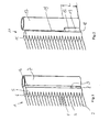
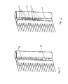
- FIGS. 4 to 6 show advantageous embodiments of a condenser with a manifold and an adjacent collector with a lateral approach, as in accordance with FIG. 1 is shown.
- FIGS. 4 to 6 are in lateral approach 30 or 40 or 50 recesses 31, 41 or 51 introduced.
- recesses are arranged in a row, wherein the recesses have an elongated contour and form webs 32 and 52 between them. It is particularly advantageous if the recesses are arranged above the region of the overflow openings.
- a single recess 41 is provided which forms substantially over the entire length of the lateral projection above the overflow openings.
- FIG. 6 shows a further embodiment of the invention, in which recesses 51 are arranged in adjacent rows, wherein the recesses 51 are formed from row to row in the axial direction offset from each other, so that a network of webs 52 is formed.
Landscapes
- Engineering & Computer Science (AREA)
- Physics & Mathematics (AREA)
- Thermal Sciences (AREA)
- Mechanical Engineering (AREA)
- General Engineering & Computer Science (AREA)
- Air-Conditioning For Vehicles (AREA)
Abstract
Description
- Die Erfindung betrifft einen Kondensator, insbesondere nach dem Oberbegriff von Anspruch 1.
- Die
WO 2004/025196 A1 offenbart einen Kondensator mit einem Rohr-Rippen-Block und beiderseits des Rohr-Rippen-Blocks angeordneten Sammelrohren, wobei die Rohre des Rohr-Rippen-Blocks durch Öffnungen der Sammelrohre greifen und mit dem Innenraum der Sammelrohre in Fluidverbindung stehen, wobei parallel zu einem der Sammelrohre ein erfindungsgemäßer Sammler angeordnet ist, welcher mittels seiner beiden Überströmöffnungen über Überströmöffnungen im Sammelrohr mit dem Sammelrohr fluidverbunden ist. - Der Sammler ist gemäß dieser Druckschrift ist als Rohr mit eingelöteten Deckeln ausgebildet, wobei die Überströmöffnungen durch hervorragende Durchzüge gebildet sind.
- Es ist die Aufgabe der Erfindung, einen Kondensator mit einem extrudierten Sammler benachbart zu einem Sammelrohr zu schaffen, der einfach und kostengünstig herstellbar ist und dennoch eine gute thermische Trennung zwischen dem Sammler und dem Sammelrohr aufweist.
- Die Aufgabe wird erreicht mit den Merkmalen von Anspruch 1, wonach ein Kondensator mit einem Rohr-Rippen-Block und beiderseits des Rohr-Rippen-Blocks angeordneten Sammelrohren, wobei die Rohre des Rohr-Rippen-Blocks durch Öffnungen der Sammelrohre greifen und mit dem Innenraum der Sammelrohre in Fluidverbindung stehen, wobei parallel zu mindestens einem der Sammelrohre ein extrudierter Sammler angeordnet ist und mit dem Sammelrohr verbunden ist, welcher mittels Überströmöffnungen mit dem Sammelrohr fluidverbunden ist, dadurch gekennzeichnet, dass zwischen dem Sammler und dem Sammelrohr eine thermische Trennung vorgesehen ist. Dadurch wird erreicht, dass eine Erwärmung des Kältemittels im Sammler nicht oder nur geringfügig durch das wärmere Kältemittel im parallel dazu angeordneten Sammelrohr erwärmt wird.
- Dabei ist es vorteilhaft, wenn der Sammler einen seitlichen Ansatz aufweist, in welchem Überströmöffnungen angeordnet sind, wobei der Sammler nur im Bereich des seitlichen Ansatzes mit dem Sammelrohr verbunden ist, wobei die axiale Länge des seitlichen Ansatzes auf die Aufnahme der Überströmöffnungen beschränkt ist. Dadurch wird lediglich im Bereich der Überströmöffnungen eine thermische Brücke erzeugt, die von der thermischen Leitfähigkeit und den beiderseits der thermischen Brücke vorliegenden Temperaturen in Bezug auf ein Verdampfen des Kältemittels im Sammler unkritisch ist.
- Zweckmäßig ist es auch, wenn der Sammler einen seitlichen Ansatz aufweist, in welchem Überströmöffnungen angeordnet sind, wobei ein Wandbereich des Sammelrohrs mit dem Sammler mit dem dazwischen angeordneten seitlichen Ansatz einteilig ausgebildet ist. Dadurch kann die Teilezahl reduziert werden, was kostengünstig realisiert werden kann.
- Auch ist es zweckmäßig, wenn die thermische Trennung in dem seitlichen Ansatz durch zumindest eine Ausnehmung ausgebildet ist.
- Dabei ist es zweckmäßig, wenn eine Ausnehmung oberhalb der Überströmöffnungen angeordnet ist, die sich bis zu einem entfernten axialen Ende des Sammlers erstreckt.
- Auch ist es zweckmäßig, wenn die Ausnehmung an dem axialen Ende des Sammlers offen ist. Dadurch wird ein einseitig offener Spalt erzeugt, welcher als thermische Trennung dient.
- Auch ist es zweckmäßig, wenn die Ausnehmung an dem axialen Ende des Sammlers durch einen Steg unterbrochen ist. Der Steg ist dabei beispielsweise ein dünner Steg, der eine geringe Leitfähigkeit aufweist.
- Auch ist es vorteilhaft, wenn eine Mehrzahl von Ausnehmungen oberhalb der Überströmöffnungen angeordnet sind, die sich bis zu einem entfernten axialen Ende des Sammlers erstrecken. Dadurch wird eine Art Netz von Stegen erzeugt, was die thermische Leitfähigkeit reduziert.
- Auch ist es zweckmäßig, wenn eine Mehrzahl von Ausnehmungen vorgesehen sind, die in einer Reihe oder in mehreren Reihen benachbart zueinander angeordnet sind und jeweils durch Stege voneinander getrennt sind. Dadurch wird eine Art geordnetes Netz von Stegen erzeugt, was die thermische Leitfähigkeit reduziert.
- Dabei ist es zweckmäßig, wenn die Ausnehmungen eine runde oder eine längliche Kontur aufweisen. Dadurch kann eine größere Anzahl von Stege erzeugt werden, die definierte Abstände zueinander aufweisen.
- Weitere vorteilhafte Ausgestaltungen sind durch die nachfolgende Figurenbeschreibung und durch die Unteransprüche beschrieben,
- Nachstehend wird die Erfindung auf der Grundlage zumindest eines Ausführungsbeispiels anhand der Zeichnungen näher erläutert. Es zeigen:
- Fig. 1
- eine schematische Teilansicht eines Kondensators mit einem Sammler,
- Fig. 2
- eine schematische Teilansicht eines Kondensators mit einem Sammler,
- Fig. 3
- eine schematische Teilansicht eines Kondensators mit einem Sammler,
- Fig. 4
- eine schematische Teilansicht eines Kondensators mit einem Sammler,
- Fig. 5
- eine schematische Teilansicht eines Kondensators mit einem Sammler, und
- Fig. 6
- eine schematische Teilansicht eines Kondensators mit einem Sammler.
- Die
Figur 1 zeigt in einer schematischen Darstellung einen Kondensator 1 mit einem Rohr-Rippen-Block 2, welcher gebildet ist durch eine Mehrzahl von beabstandet zueinander angeordneten Rohren 3 und dazwischen angeordneten Rippen 4. Die Rohre 3 sind mit beiderseits des Rohr-Rippen-Blocks angeordneten Sammelrohren 5 verbunden, in dem die Rohre 3 durch Öffnungen 6 des Sammelrohrs 5 eingreifen und abgedichtet darin angeordnet sind, so dass eine Fluidverbindung zwischen dem Innenraum des Rohrs 3 und dem Innenraum des Sammelrohrs 5 vorhanden ist. Parallel zu einem der Sammelrohre 5 ist ein Sammler 7 angeordnet, welcher über Überströmöffnungen 8, 9 mit dem Sammelrohr 5 in Fluidverbindung steht. - Im Beispiel der
Figur 1 ist der Sammler 7 mit dem Sammelrohr 5 einstückig ausgebildet, wobei der Sammler 7 mit dem Sammelrohr 5 beispielsweise als extrudiertes Bauteil in einem Prozess hergestellt wird, wobei das dadurch erhaltene Profil anschließend durch beispielsweise spanende oder spanlose Bearbeitung weiterverarbeitet werden kann, um beispielsweise die Überströmöffnungen 8, 9 beziehungsweise die Rohröffnungen 6 einzubringen. - Die
Figur 2 zeigt einen Teil eines Kondensators 11 mit einem Sammelrohr 15 und einem Sammler 17. Dabei ist die Verbindung zwischen dem Sammelrohr 15 und dem Sammer 17 auf den Bereich 18 der Überströmöffnungen 12, 13 beschränkt, wobei die Überströmöffnungen in einem Block angeordnet sind, der zwischen dem Sammelrohr 15 und dem Sammler 17 vorliegt. Oberhalb des Blocks 18 ist eine thermische Trennung 19 zwischen dem Sammelrohr 15 und dem Sammler 17 ausgebildet. - Die beiden
Figuren 1, 2 zeigen, dass der Sammler 17 einen seitlichen Ansatz 10, 18 aufweist, in welchem die Überströmöffnungen 8, 9, 12, 13 angeordnet sind, wobei der Sammler 7, 17 nur im Bereich dieses seitlichen Ansatzes mit dem Sammelrohr 5, 15 verbunden ist. Im Ausführungsbeispiel derFigur 2 ist der Sammler 17 nur im Bereich des seitlichen Ansatzes mit dem benachbarten Sammelrohr 15 verbunden, wobei die axiale Länge L des seitlichen Ansatzes derart dimensioniert ist, dass er auf die Aufnahme der Überströmöffnungen beschränkt ist. - Es ist bereits erwähnt, dass der Sammler mit seinem seitlichen Ansatz und das Sammelrohr einteilig ausgebildet sein können, wie beispielsweise durch Extrudieren. Alternativ dazu kann auch der Sammler mit seinem seitlichen Ansatz und ein Wandbereich des Sammelrohres einteilig ausgebildet sein. Dabei ist das Sammelrohr bevorzugt zweiteilig ausgebildet, mit einem Boden, in welchem die Öffnungen 6 eingebracht sind und einen Deckel, der den Boden zu einem geschlossenen Rohr verschließt. Dabei ist der Wandbereich, der mit dem Sammelrohr einteilig ausgebildet ist, bevorzugt der Deckel des Sammelrohrs.
- Die
Figur 3 zeigt ein weiteres Ausführungsbeispiel in einer Teilansicht eines Kondensators 21 mit einem Sammelrohr 25 und einem Sammler 27, wobei oberhalb des seitlichen Ansatzes 28 eine thermische Trennung 29 vorgesehen ist. Am axialen Ende 22, welches von dem axialen Ende 23 des Sammlers beabstandet ist, an welchem der seitliche Ansatz 28 angeordnet ist, ist ein Steg 24 zur Verbindung zwischen dem Sammelrohr 25 oder zwischen einem Wandbereich des Sammelrohrs 25 einerseits und dem Sammler 27 andererseits vorgesehen. Hierbei kann es ebenso vorteilhaft und zweckmäßig sein, wenn der Sammler 27 mit dem Steg 24 und dem seitlichen Ansatz 28 sowie mit dem Sammelrohr oder zumindest mit einem Wandbereich des Sammelrohrs einstückig durch Extrudieren ausgebildet ist. - Die
Figuren 4 bis 6 zeigen vorteilhafte Ausgestaltungen eines Kondensators mit einem Sammelrohr und einem benachbarten Sammler mit einem seitlichen Ansatz, wie er gemäßFigur 1 gezeigt ist. In denFiguren 4 bis 6 sind im seitlichen Ansatz 30 beziehungsweise 40 beziehungsweise 50 Ausnehmungen 31, 41 oder 51 eingebracht. Im Ausführungsbeispiel derFigur 4 sind Ausnehmungen in einer Reihe angeordnet, wobei die Ausnehmungen eine längliche Kontur aufweisen und zwischen sich Stege 32 bzw. 52 ausbilden. Dabei ist es besonders vorteilhaft, wenn die Ausnehmungen oberhalb des Bereichs der Überströmöffnungen angeordnet sind. Im Ausführungsbeispiel derFigur 5 ist eine einzige Ausnehmung 41 vorgesehen, die sich im Wesentlichen über die gesamte Länge des seitlichen Ansatzes oberhalb der Überströmöffnungen ausbildet. - Die
Figur 6 zeigt ein weiteres Ausführungsbeispiel der Erfindung, bei welchem Ausnehmungen 51 in benachbarten Reihen angeordnet sind, wobei die Ausnehmungen 51 von Reihe zu Reihe in axialer Richtung versetzt zueinander ausgebildet sind, so dass sich ein Netzwerk von Stegen 52 bildet.
Claims (10)
- Kondensator mit einem Rohr-Rippen-Block und beiderseits des Rohr-Rippen-Blocks angeordneten Sammelrohren, wobei die Rohre des Rohr-Rippen-Blocks durch Öffnungen der Sammelrohre greifen und mit dem Innenraum der Sammelrohre in Fluidverbindung stehen, wobei parallel zu mindestens einem der Sammelrohre ein extrudierter Sammler angeordnet ist und mit dem Sammelrohr verbunden ist, welcher mittels Überströmöffnungen mit dem Sammelrohr fluidverbunden ist, dadurch gekennzeichnet, dass zwischen dem Sammler und dem Sammelrohr eine thermische Trennung vorgesehen ist.
- Kondensator nach Anspruch 1, dadurch gekennzeichnet, dass der Sammler einen seitlichen Ansatz aufweist, in welchem Überströmöffnungen angeordnet sind, wobei der Sammler nur im Bereich des seitlichen Ansatzes mit dem Sammelrohr verbunden ist, wobei die axiale Länge des seitlichen Ansatzes auf die Aufnahme der Überströmöffnungen beschränkt ist.
- Kondensator nach Anspruch 1, dadurch gekennzeichnet, dass der Sammler einen seitlichen Ansatz aufweist, in welchem Überströmöffnungen angeordnet sind, wobei ein Wandbereich des Sammelrohrs mit dem Sammler mit dem dazwischen angeordneten seitlichen Ansatz einteilig ausgebildet ist.
- Kondensator nach Anspruch 3, dadurch gekennzeichnet, dass die thermische Trennung in dem seitlichen Ansatz durch zumindest eine Ausnehmung ausgebildet ist.
- Kondensator nach Anspruch 4, dadurch gekennzeichnet, dass eine Ausnehmung oberhalb der Überströmöffnungen angeordnet ist, die sich bis zu einem entfernten axialen Ende des Sammlers erstreckt.
- Kondensator nach Anspruch 5, dadurch gekennzeichnet, dass die Ausnehmung an dem axialen Ende des Sammlers offen ist.
- Kondensator nach Anspruch 5, dadurch gekennzeichnet, dass die Ausnehmung an dem axialen Ende des Sammlers durch einen Steg unterbrochen ist.
- Kondensator nach Anspruch 4, dadurch gekennzeichnet, dass eine Mehrzahl von Ausnehmungen oberhalb der Überströmöffnungen angeordnet sind, die sich bis zu einem entfernten axialen Ende des Sammlers erstrecken.
- Kondensator nach Anspruch 8, dadurch gekennzeichnet, dass eine Mehrzahl von Ausnehmungen in einer Reihe oder in mehreren Reihen benachbart zueinander angeordnet sind und jeweils durch Stege voneinander getrennt sind.
- Kondensator nach einem der vorhergehenden Ansprüche 4 bis 9, dadurch gekennzeichnet, dass die Ausnehmungen eine runde oder eine längliche Kontur aufweisen.
Priority Applications (1)
| Application Number | Priority Date | Filing Date | Title |
|---|---|---|---|
| EP12290252.1A EP2690382B1 (de) | 2012-07-23 | 2012-07-23 | Kondensator |
Applications Claiming Priority (1)
| Application Number | Priority Date | Filing Date | Title |
|---|---|---|---|
| EP12290252.1A EP2690382B1 (de) | 2012-07-23 | 2012-07-23 | Kondensator |
Publications (2)
| Publication Number | Publication Date |
|---|---|
| EP2690382A1 true EP2690382A1 (de) | 2014-01-29 |
| EP2690382B1 EP2690382B1 (de) | 2019-10-02 |
Family
ID=47002783
Family Applications (1)
| Application Number | Title | Priority Date | Filing Date |
|---|---|---|---|
| EP12290252.1A Active EP2690382B1 (de) | 2012-07-23 | 2012-07-23 | Kondensator |
Country Status (1)
| Country | Link |
|---|---|
| EP (1) | EP2690382B1 (de) |
Citations (5)
| Publication number | Priority date | Publication date | Assignee | Title |
|---|---|---|---|---|
| US5228315A (en) * | 1990-12-28 | 1993-07-20 | Zexel Corporation | Condenser having a receiver tank formed integrally therewith |
| JP2000039290A (ja) * | 1998-07-22 | 2000-02-08 | Suzuki Motor Corp | 熱交換装置 |
| JP2003161548A (ja) * | 2001-11-21 | 2003-06-06 | Nikkei Nekko Kk | 受液器付き熱交換器 |
| JP2003314928A (ja) * | 2002-04-19 | 2003-11-06 | Denso Corp | 受液器一体型凝縮器 |
| WO2004025196A1 (de) | 2002-08-31 | 2004-03-25 | Behr Gmbh & Co. | Kältemittelkondensator, insbesondere für kratfahrzeug-klimaanlagen |
-
2012
- 2012-07-23 EP EP12290252.1A patent/EP2690382B1/de active Active
Patent Citations (5)
| Publication number | Priority date | Publication date | Assignee | Title |
|---|---|---|---|---|
| US5228315A (en) * | 1990-12-28 | 1993-07-20 | Zexel Corporation | Condenser having a receiver tank formed integrally therewith |
| JP2000039290A (ja) * | 1998-07-22 | 2000-02-08 | Suzuki Motor Corp | 熱交換装置 |
| JP2003161548A (ja) * | 2001-11-21 | 2003-06-06 | Nikkei Nekko Kk | 受液器付き熱交換器 |
| JP2003314928A (ja) * | 2002-04-19 | 2003-11-06 | Denso Corp | 受液器一体型凝縮器 |
| WO2004025196A1 (de) | 2002-08-31 | 2004-03-25 | Behr Gmbh & Co. | Kältemittelkondensator, insbesondere für kratfahrzeug-klimaanlagen |
Also Published As
| Publication number | Publication date |
|---|---|
| EP2690382B1 (de) | 2019-10-02 |
Similar Documents
| Publication | Publication Date | Title |
|---|---|---|
| DE60011616T2 (de) | Wärmetauscher mit mehrkanalrohren | |
| DE102015119863B4 (de) | Elektrische Heizvorrichtung zum Heizen von Fluiden | |
| EP2151655B1 (de) | Wärmetauscher, Verwendung und Herstellungsverfahren eines Wärmetauschers | |
| EP3106823B1 (de) | Wärmeübertrager | |
| DE2241407A1 (de) | Waermetauscher und verfahren zu ihrer herstellung | |
| DE102018122414B4 (de) | Temperiervorrichtung und Verfahren zum Temperieren eines Elektromoduls | |
| DE19719256A1 (de) | Mehrflutiger Flachrohrwärmetauscher für Kraftfahrzeuge mit Umlenkboden sowie Herstellungsverfahren | |
| DE102015216719A1 (de) | Kühlplatte eines Batteriekühlers | |
| EP3042140B1 (de) | Rohrboden | |
| DE202008000574U1 (de) | Verbindungseinrichtung | |
| DE112017002106T5 (de) | Wärmetauscher | |
| DE202017102436U1 (de) | Wärmetauscher mit Mikrokanal-Struktur oder Flügelrohr-Struktur | |
| DE202017104743U1 (de) | Wärmetauscher mit Mikrokanal-Struktur oder Flügelrohr-Struktur | |
| EP2927632A1 (de) | Wärmetauscher | |
| EP2690382B1 (de) | Kondensator | |
| DE3432231A1 (de) | Waermetauscher | |
| DE102006018688A1 (de) | Verfahren zum Biegen von Flachrohren für Wärmeübertrager und gebogenes Flachrohr | |
| DE102005032852B4 (de) | Lagerschale und Verfahren zu ihrer Herstellung | |
| EP2690381B1 (de) | Kondensator und Sammler für einen Kondensator | |
| DE102008061762A1 (de) | Sammler eines Wärmeübertragers, insbesondere für eine Klimaanlage eines Kraftfahrzeuges sowie Wärmeübertrager, insbesondere Verdampfer für eine Kraftfahrzeugklimaanlage | |
| DE1961218A1 (de) | Waermetauscherrohrbuendel und gewellte Einlagen | |
| DE102006005421A1 (de) | Wärmetauscher | |
| EP2677263B1 (de) | Wärmeübertrager | |
| EP1712868B1 (de) | Wärmeübertrager | |
| DE102018215937A1 (de) | Kühlfluidführende Kühlkanalstruktur |
Legal Events
| Date | Code | Title | Description |
|---|---|---|---|
| PUAI | Public reference made under article 153(3) epc to a published international application that has entered the european phase |
Free format text: ORIGINAL CODE: 0009012 |
|
| AK | Designated contracting states |
Kind code of ref document: A1 Designated state(s): AL AT BE BG CH CY CZ DE DK EE ES FI FR GB GR HR HU IE IS IT LI LT LU LV MC MK MT NL NO PL PT RO RS SE SI SK SM TR |
|
| AX | Request for extension of the european patent |
Extension state: BA ME |
|
| 17P | Request for examination filed |
Effective date: 20140729 |
|
| RBV | Designated contracting states (corrected) |
Designated state(s): AL AT BE BG CH CY CZ DE DK EE ES FI FR GB GR HR HU IE IS IT LI LT LU LV MC MK MT NL NO PL PT RO RS SE SI SK SM TR |
|
| RAP1 | Party data changed (applicant data changed or rights of an application transferred) |
Owner name: MAHLE BEHR GMBH & CO. KG Owner name: BEHR FRANCE HAMBACH S.A.R.L. |
|
| RAP1 | Party data changed (applicant data changed or rights of an application transferred) |
Owner name: MAHLE BEHR GMBH & CO. KG Owner name: MAHLE BEHR FRANCE HAMBACH S.A.S |
|
| 17Q | First examination report despatched |
Effective date: 20160307 |
|
| STAA | Information on the status of an ep patent application or granted ep patent |
Free format text: STATUS: EXAMINATION IS IN PROGRESS |
|
| GRAP | Despatch of communication of intention to grant a patent |
Free format text: ORIGINAL CODE: EPIDOSNIGR1 |
|
| STAA | Information on the status of an ep patent application or granted ep patent |
Free format text: STATUS: GRANT OF PATENT IS INTENDED |
|
| INTG | Intention to grant announced |
Effective date: 20190329 |
|
| GRAJ | Information related to disapproval of communication of intention to grant by the applicant or resumption of examination proceedings by the epo deleted |
Free format text: ORIGINAL CODE: EPIDOSDIGR1 |
|
| GRAP | Despatch of communication of intention to grant a patent |
Free format text: ORIGINAL CODE: EPIDOSNIGR1 |
|
| INTG | Intention to grant announced |
Effective date: 20190611 |
|
| RIN1 | Information on inventor provided before grant (corrected) |
Inventor name: JUNG, PATRICK Inventor name: FOERSTER, UWE Inventor name: KASPAR, MARTIN |
|
| GRAS | Grant fee paid |
Free format text: ORIGINAL CODE: EPIDOSNIGR3 |
|
| GRAA | (expected) grant |
Free format text: ORIGINAL CODE: 0009210 |
|
| STAA | Information on the status of an ep patent application or granted ep patent |
Free format text: STATUS: THE PATENT HAS BEEN GRANTED |
|
| AK | Designated contracting states |
Kind code of ref document: B1 Designated state(s): AL AT BE BG CH CY CZ DE DK EE ES FI FR GB GR HR HU IE IS IT LI LT LU LV MC MK MT NL NO PL PT RO RS SE SI SK SM TR |
|
| REG | Reference to a national code |
Ref country code: GB Ref legal event code: FG4D Free format text: NOT ENGLISH |
|
| REG | Reference to a national code |
Ref country code: CH Ref legal event code: EP Ref country code: AT Ref legal event code: REF Ref document number: 1186630 Country of ref document: AT Kind code of ref document: T Effective date: 20191015 |
|
| REG | Reference to a national code |
Ref country code: DE Ref legal event code: R096 Ref document number: 502012015346 Country of ref document: DE |
|
| REG | Reference to a national code |
Ref country code: IE Ref legal event code: FG4D Free format text: LANGUAGE OF EP DOCUMENT: GERMAN |
|
| REG | Reference to a national code |
Ref country code: NL Ref legal event code: MP Effective date: 20191002 |
|
| REG | Reference to a national code |
Ref country code: LT Ref legal event code: MG4D |
|
| PG25 | Lapsed in a contracting state [announced via postgrant information from national office to epo] |
Ref country code: LV Free format text: LAPSE BECAUSE OF FAILURE TO SUBMIT A TRANSLATION OF THE DESCRIPTION OR TO PAY THE FEE WITHIN THE PRESCRIBED TIME-LIMIT Effective date: 20191002 Ref country code: SE Free format text: LAPSE BECAUSE OF FAILURE TO SUBMIT A TRANSLATION OF THE DESCRIPTION OR TO PAY THE FEE WITHIN THE PRESCRIBED TIME-LIMIT Effective date: 20191002 Ref country code: NL Free format text: LAPSE BECAUSE OF FAILURE TO SUBMIT A TRANSLATION OF THE DESCRIPTION OR TO PAY THE FEE WITHIN THE PRESCRIBED TIME-LIMIT Effective date: 20191002 Ref country code: ES Free format text: LAPSE BECAUSE OF FAILURE TO SUBMIT A TRANSLATION OF THE DESCRIPTION OR TO PAY THE FEE WITHIN THE PRESCRIBED TIME-LIMIT Effective date: 20191002 Ref country code: GR Free format text: LAPSE BECAUSE OF FAILURE TO SUBMIT A TRANSLATION OF THE DESCRIPTION OR TO PAY THE FEE WITHIN THE PRESCRIBED TIME-LIMIT Effective date: 20200103 Ref country code: PL Free format text: LAPSE BECAUSE OF FAILURE TO SUBMIT A TRANSLATION OF THE DESCRIPTION OR TO PAY THE FEE WITHIN THE PRESCRIBED TIME-LIMIT Effective date: 20191002 Ref country code: NO Free format text: LAPSE BECAUSE OF FAILURE TO SUBMIT A TRANSLATION OF THE DESCRIPTION OR TO PAY THE FEE WITHIN THE PRESCRIBED TIME-LIMIT Effective date: 20200102 Ref country code: PT Free format text: LAPSE BECAUSE OF FAILURE TO SUBMIT A TRANSLATION OF THE DESCRIPTION OR TO PAY THE FEE WITHIN THE PRESCRIBED TIME-LIMIT Effective date: 20200203 Ref country code: FI Free format text: LAPSE BECAUSE OF FAILURE TO SUBMIT A TRANSLATION OF THE DESCRIPTION OR TO PAY THE FEE WITHIN THE PRESCRIBED TIME-LIMIT Effective date: 20191002 Ref country code: BG Free format text: LAPSE BECAUSE OF FAILURE TO SUBMIT A TRANSLATION OF THE DESCRIPTION OR TO PAY THE FEE WITHIN THE PRESCRIBED TIME-LIMIT Effective date: 20200102 Ref country code: LT Free format text: LAPSE BECAUSE OF FAILURE TO SUBMIT A TRANSLATION OF THE DESCRIPTION OR TO PAY THE FEE WITHIN THE PRESCRIBED TIME-LIMIT Effective date: 20191002 |
|
| PG25 | Lapsed in a contracting state [announced via postgrant information from national office to epo] |
Ref country code: HR Free format text: LAPSE BECAUSE OF FAILURE TO SUBMIT A TRANSLATION OF THE DESCRIPTION OR TO PAY THE FEE WITHIN THE PRESCRIBED TIME-LIMIT Effective date: 20191002 Ref country code: RS Free format text: LAPSE BECAUSE OF FAILURE TO SUBMIT A TRANSLATION OF THE DESCRIPTION OR TO PAY THE FEE WITHIN THE PRESCRIBED TIME-LIMIT Effective date: 20191002 Ref country code: IS Free format text: LAPSE BECAUSE OF FAILURE TO SUBMIT A TRANSLATION OF THE DESCRIPTION OR TO PAY THE FEE WITHIN THE PRESCRIBED TIME-LIMIT Effective date: 20200224 Ref country code: CZ Free format text: LAPSE BECAUSE OF FAILURE TO SUBMIT A TRANSLATION OF THE DESCRIPTION OR TO PAY THE FEE WITHIN THE PRESCRIBED TIME-LIMIT Effective date: 20191002 |
|
| PG25 | Lapsed in a contracting state [announced via postgrant information from national office to epo] |
Ref country code: AL Free format text: LAPSE BECAUSE OF FAILURE TO SUBMIT A TRANSLATION OF THE DESCRIPTION OR TO PAY THE FEE WITHIN THE PRESCRIBED TIME-LIMIT Effective date: 20191002 |
|
| REG | Reference to a national code |
Ref country code: DE Ref legal event code: R097 Ref document number: 502012015346 Country of ref document: DE |
|
| PG2D | Information on lapse in contracting state deleted |
Ref country code: IS |
|
| PG25 | Lapsed in a contracting state [announced via postgrant information from national office to epo] |
Ref country code: RO Free format text: LAPSE BECAUSE OF FAILURE TO SUBMIT A TRANSLATION OF THE DESCRIPTION OR TO PAY THE FEE WITHIN THE PRESCRIBED TIME-LIMIT Effective date: 20191002 Ref country code: EE Free format text: LAPSE BECAUSE OF FAILURE TO SUBMIT A TRANSLATION OF THE DESCRIPTION OR TO PAY THE FEE WITHIN THE PRESCRIBED TIME-LIMIT Effective date: 20191002 Ref country code: DK Free format text: LAPSE BECAUSE OF FAILURE TO SUBMIT A TRANSLATION OF THE DESCRIPTION OR TO PAY THE FEE WITHIN THE PRESCRIBED TIME-LIMIT Effective date: 20191002 Ref country code: IS Free format text: LAPSE BECAUSE OF FAILURE TO SUBMIT A TRANSLATION OF THE DESCRIPTION OR TO PAY THE FEE WITHIN THE PRESCRIBED TIME-LIMIT Effective date: 20200202 |
|
| PLBE | No opposition filed within time limit |
Free format text: ORIGINAL CODE: 0009261 |
|
| STAA | Information on the status of an ep patent application or granted ep patent |
Free format text: STATUS: NO OPPOSITION FILED WITHIN TIME LIMIT |
|
| PG25 | Lapsed in a contracting state [announced via postgrant information from national office to epo] |
Ref country code: IT Free format text: LAPSE BECAUSE OF FAILURE TO SUBMIT A TRANSLATION OF THE DESCRIPTION OR TO PAY THE FEE WITHIN THE PRESCRIBED TIME-LIMIT Effective date: 20191002 Ref country code: SK Free format text: LAPSE BECAUSE OF FAILURE TO SUBMIT A TRANSLATION OF THE DESCRIPTION OR TO PAY THE FEE WITHIN THE PRESCRIBED TIME-LIMIT Effective date: 20191002 Ref country code: SM Free format text: LAPSE BECAUSE OF FAILURE TO SUBMIT A TRANSLATION OF THE DESCRIPTION OR TO PAY THE FEE WITHIN THE PRESCRIBED TIME-LIMIT Effective date: 20191002 |
|
| 26N | No opposition filed |
Effective date: 20200703 |
|
| PG25 | Lapsed in a contracting state [announced via postgrant information from national office to epo] |
Ref country code: SI Free format text: LAPSE BECAUSE OF FAILURE TO SUBMIT A TRANSLATION OF THE DESCRIPTION OR TO PAY THE FEE WITHIN THE PRESCRIBED TIME-LIMIT Effective date: 20191002 |
|
| PG25 | Lapsed in a contracting state [announced via postgrant information from national office to epo] |
Ref country code: MC Free format text: LAPSE BECAUSE OF FAILURE TO SUBMIT A TRANSLATION OF THE DESCRIPTION OR TO PAY THE FEE WITHIN THE PRESCRIBED TIME-LIMIT Effective date: 20191002 |
|
| REG | Reference to a national code |
Ref country code: CH Ref legal event code: PL |
|
| GBPC | Gb: european patent ceased through non-payment of renewal fee |
Effective date: 20200723 |
|
| REG | Reference to a national code |
Ref country code: BE Ref legal event code: MM Effective date: 20200731 |
|
| PG25 | Lapsed in a contracting state [announced via postgrant information from national office to epo] |
Ref country code: FR Free format text: LAPSE BECAUSE OF NON-PAYMENT OF DUE FEES Effective date: 20200731 Ref country code: GB Free format text: LAPSE BECAUSE OF NON-PAYMENT OF DUE FEES Effective date: 20200723 Ref country code: LU Free format text: LAPSE BECAUSE OF NON-PAYMENT OF DUE FEES Effective date: 20200723 Ref country code: CH Free format text: LAPSE BECAUSE OF NON-PAYMENT OF DUE FEES Effective date: 20200731 Ref country code: LI Free format text: LAPSE BECAUSE OF NON-PAYMENT OF DUE FEES Effective date: 20200731 |
|
| PG25 | Lapsed in a contracting state [announced via postgrant information from national office to epo] |
Ref country code: BE Free format text: LAPSE BECAUSE OF NON-PAYMENT OF DUE FEES Effective date: 20200731 |
|
| PG25 | Lapsed in a contracting state [announced via postgrant information from national office to epo] |
Ref country code: IE Free format text: LAPSE BECAUSE OF NON-PAYMENT OF DUE FEES Effective date: 20200723 |
|
| REG | Reference to a national code |
Ref country code: AT Ref legal event code: MM01 Ref document number: 1186630 Country of ref document: AT Kind code of ref document: T Effective date: 20200723 |
|
| PG25 | Lapsed in a contracting state [announced via postgrant information from national office to epo] |
Ref country code: AT Free format text: LAPSE BECAUSE OF NON-PAYMENT OF DUE FEES Effective date: 20200723 |
|
| PG25 | Lapsed in a contracting state [announced via postgrant information from national office to epo] |
Ref country code: TR Free format text: LAPSE BECAUSE OF FAILURE TO SUBMIT A TRANSLATION OF THE DESCRIPTION OR TO PAY THE FEE WITHIN THE PRESCRIBED TIME-LIMIT Effective date: 20191002 Ref country code: MT Free format text: LAPSE BECAUSE OF FAILURE TO SUBMIT A TRANSLATION OF THE DESCRIPTION OR TO PAY THE FEE WITHIN THE PRESCRIBED TIME-LIMIT Effective date: 20191002 Ref country code: CY Free format text: LAPSE BECAUSE OF FAILURE TO SUBMIT A TRANSLATION OF THE DESCRIPTION OR TO PAY THE FEE WITHIN THE PRESCRIBED TIME-LIMIT Effective date: 20191002 |
|
| PG25 | Lapsed in a contracting state [announced via postgrant information from national office to epo] |
Ref country code: MK Free format text: LAPSE BECAUSE OF FAILURE TO SUBMIT A TRANSLATION OF THE DESCRIPTION OR TO PAY THE FEE WITHIN THE PRESCRIBED TIME-LIMIT Effective date: 20191002 |
|
| P01 | Opt-out of the competence of the unified patent court (upc) registered |
Free format text: CASE NUMBER: APP_36376/2024 Effective date: 20240618 |
|
| PGFP | Annual fee paid to national office [announced via postgrant information from national office to epo] |
Ref country code: DE Payment date: 20250722 Year of fee payment: 14 |