EP2690334A2 - Flue gas/combustion air pipe system - Google Patents
Flue gas/combustion air pipe system Download PDFInfo
- Publication number
- EP2690334A2 EP2690334A2 EP13165539.1A EP13165539A EP2690334A2 EP 2690334 A2 EP2690334 A2 EP 2690334A2 EP 13165539 A EP13165539 A EP 13165539A EP 2690334 A2 EP2690334 A2 EP 2690334A2
- Authority
- EP
- European Patent Office
- Prior art keywords
- pipe
- outer tube
- exhaust
- pipe system
- exhaust pipe
- Prior art date
- Legal status (The legal status is an assumption and is not a legal conclusion. Google has not performed a legal analysis and makes no representation as to the accuracy of the status listed.)
- Granted
Links
Images
Classifications
-
- F—MECHANICAL ENGINEERING; LIGHTING; HEATING; WEAPONS; BLASTING
- F16—ENGINEERING ELEMENTS AND UNITS; GENERAL MEASURES FOR PRODUCING AND MAINTAINING EFFECTIVE FUNCTIONING OF MACHINES OR INSTALLATIONS; THERMAL INSULATION IN GENERAL
- F16L—PIPES; JOINTS OR FITTINGS FOR PIPES; SUPPORTS FOR PIPES, CABLES OR PROTECTIVE TUBING; MEANS FOR THERMAL INSULATION IN GENERAL
- F16L9/00—Rigid pipes
- F16L9/18—Double-walled pipes; Multi-channel pipes or pipe assemblies
- F16L9/19—Multi-channel pipes or pipe assemblies
- F16L9/20—Pipe assemblies
-
- F—MECHANICAL ENGINEERING; LIGHTING; HEATING; WEAPONS; BLASTING
- F16—ENGINEERING ELEMENTS AND UNITS; GENERAL MEASURES FOR PRODUCING AND MAINTAINING EFFECTIVE FUNCTIONING OF MACHINES OR INSTALLATIONS; THERMAL INSULATION IN GENERAL
- F16L—PIPES; JOINTS OR FITTINGS FOR PIPES; SUPPORTS FOR PIPES, CABLES OR PROTECTIVE TUBING; MEANS FOR THERMAL INSULATION IN GENERAL
- F16L41/00—Branching pipes; Joining pipes to walls
- F16L41/002—Branching pipes; Joining pipes to walls of concrete, cement or asbestos-cement
-
- F—MECHANICAL ENGINEERING; LIGHTING; HEATING; WEAPONS; BLASTING
- F16—ENGINEERING ELEMENTS AND UNITS; GENERAL MEASURES FOR PRODUCING AND MAINTAINING EFFECTIVE FUNCTIONING OF MACHINES OR INSTALLATIONS; THERMAL INSULATION IN GENERAL
- F16L—PIPES; JOINTS OR FITTINGS FOR PIPES; SUPPORTS FOR PIPES, CABLES OR PROTECTIVE TUBING; MEANS FOR THERMAL INSULATION IN GENERAL
- F16L41/00—Branching pipes; Joining pipes to walls
- F16L41/08—Joining pipes to walls or pipes, the joined pipe axis being perpendicular to the plane of the wall or to the axis of another pipe
- F16L41/088—Joining pipes to walls or pipes, the joined pipe axis being perpendicular to the plane of the wall or to the axis of another pipe fixed using an elastic grommet between the extremity of the tube and the wall
-
- F—MECHANICAL ENGINEERING; LIGHTING; HEATING; WEAPONS; BLASTING
- F16—ENGINEERING ELEMENTS AND UNITS; GENERAL MEASURES FOR PRODUCING AND MAINTAINING EFFECTIVE FUNCTIONING OF MACHINES OR INSTALLATIONS; THERMAL INSULATION IN GENERAL
- F16L—PIPES; JOINTS OR FITTINGS FOR PIPES; SUPPORTS FOR PIPES, CABLES OR PROTECTIVE TUBING; MEANS FOR THERMAL INSULATION IN GENERAL
- F16L45/00—Pipe units with cleaning aperture and closure therefor
-
- F—MECHANICAL ENGINEERING; LIGHTING; HEATING; WEAPONS; BLASTING
- F16—ENGINEERING ELEMENTS AND UNITS; GENERAL MEASURES FOR PRODUCING AND MAINTAINING EFFECTIVE FUNCTIONING OF MACHINES OR INSTALLATIONS; THERMAL INSULATION IN GENERAL
- F16L—PIPES; JOINTS OR FITTINGS FOR PIPES; SUPPORTS FOR PIPES, CABLES OR PROTECTIVE TUBING; MEANS FOR THERMAL INSULATION IN GENERAL
- F16L7/00—Supporting of pipes or cables inside other pipes or sleeves, e.g. for enabling pipes or cables to be inserted or withdrawn from under roads or railways without interruption of traffic
-
- F—MECHANICAL ENGINEERING; LIGHTING; HEATING; WEAPONS; BLASTING
- F16—ENGINEERING ELEMENTS AND UNITS; GENERAL MEASURES FOR PRODUCING AND MAINTAINING EFFECTIVE FUNCTIONING OF MACHINES OR INSTALLATIONS; THERMAL INSULATION IN GENERAL
- F16L—PIPES; JOINTS OR FITTINGS FOR PIPES; SUPPORTS FOR PIPES, CABLES OR PROTECTIVE TUBING; MEANS FOR THERMAL INSULATION IN GENERAL
- F16L9/00—Rigid pipes
- F16L9/18—Double-walled pipes; Multi-channel pipes or pipe assemblies
-
- F—MECHANICAL ENGINEERING; LIGHTING; HEATING; WEAPONS; BLASTING
- F23—COMBUSTION APPARATUS; COMBUSTION PROCESSES
- F23J—REMOVAL OR TREATMENT OF COMBUSTION PRODUCTS OR COMBUSTION RESIDUES; FLUES
- F23J13/00—Fittings for chimneys or flues
- F23J13/02—Linings; Jackets; Casings
- F23J13/025—Linings; Jackets; Casings composed of concentric elements, e.g. double walled
-
- F—MECHANICAL ENGINEERING; LIGHTING; HEATING; WEAPONS; BLASTING
- F23—COMBUSTION APPARATUS; COMBUSTION PROCESSES
- F23J—REMOVAL OR TREATMENT OF COMBUSTION PRODUCTS OR COMBUSTION RESIDUES; FLUES
- F23J13/00—Fittings for chimneys or flues
- F23J13/04—Joints; Connections
-
- F—MECHANICAL ENGINEERING; LIGHTING; HEATING; WEAPONS; BLASTING
- F23—COMBUSTION APPARATUS; COMBUSTION PROCESSES
- F23J—REMOVAL OR TREATMENT OF COMBUSTION PRODUCTS OR COMBUSTION RESIDUES; FLUES
- F23J2211/00—Flue gas duct systems
- F23J2211/10—Balanced flues (combining air supply and flue gas exhaust)
- F23J2211/101—Balanced flues (combining air supply and flue gas exhaust) with coaxial duct arrangement
Definitions
- the invention relates to a combined exhaust / combustion air pipe system according to the preamble of claim 1, comprising two, in particular coaxially nested tubes, namely a, preferably metallic outer tube and extending within the outer tube, in particular formed of plastic, exhaust pipe, wherein between the outer tube and exhaust pipe, a combustion air duct (fresh air duct) is formed for supplying combustion air to the heating burner.
- the exhaust gas runs counter to the fresh air through the exhaust pipe to the outside.
- an exhaust gas / combustion air pipe system is known, wherein for the combined axial and radial fixation of the two nested tubes relative to each other a formed of a wire strand, resilient connecting element is provided.
- the known connection element has been proven - but there are efforts to facilitate the installation of the pipe system on.
- the known pipe system also includes a control opening in the outer tube, which can be closed with a closure lid. The closure lid can be fixed to the outer tube.
- the invention is based on the object with respect to a simplified assembly to provide improved combined exhaust / combustion air pipe system, in particular for heating systems.
- the invention is based on the idea to provide combined fixing means for the simultaneous axial and radial securing of the outer tube and the exhaust pipe relative to each other and for fixing the closure cap on the outer tube. According to the invention this is achieved by at least one provided on the exhaust pipe, in particular integrally formed radial extension, on which a bolt part is fixed, which passes through the outer part of a bolt assigned to the bolt and preferably radially aligned with the radial extension, such that on the bolt part a fixing part for releasably fixing the closure cap can be arranged on the outer tube.
- At least one radial extension is provided on the exhaust pipe, preferably formed integrally with the exhaust pipe designed in particular as an injection molded part, which is suitable and intended to attach thereto, in particular made of metal bolt part, still more preferably the bolt part with a thread, in particular a External thread, at the radial extension, in particular in a radial opening, is screwed, being maintained by means of the radial extension of the formation of the combustion air duct necessary distance between the inner exhaust pipe and the outer, preferably metallic outer tube. It has proven particularly expedient if the radial extension on the inner peripheral surface of the outer tube, in particular in an edge region of the Through hole supported so as to maintain a defined radial distance between the outer tube and the exhaust pipe.
- the bolt part which is preferably screwed to the radial extension, preferably in the radial extension, cooperates with a fixing part for releasably fixing the closure lid, wherein the fixing part is preferably screwed to the bolt part to clamp the closure lid clamped to the outer tube.
- a fixing part for releasably fixing the closure lid
- the fixing part is preferably screwed to the bolt part to clamp the closure lid clamped to the outer tube.
- at least two such radial extension bolt part fixing part combinations are provided for fixing the closure cover at two circumferentially spaced locations.
- a metallic bolt part with a plastic exhaust pipe, in particular designed as a plastic injection molded part exhaust pipe, wherein the bolt part is preferably screwed with a thread, in particular an external thread, with the radial extension.
- a thread in particular an external thread
- the radial extension is advantageous to form the external thread of the bolt part as economically feasible Blechschraubenssengengine, since in this case can be dispensed with a preforming of a counter-thread, in particular an internal thread in the radial extension.
- the radial extension on a running in the radial direction receiving opening for screwing the bolt part.
- the fixing part for releasably fixing the closure cap as an internally threaded nut which is screwed onto a corresponding external thread of the bolt part, wherein said external thread protrudes from the through hole in the preferably metallic outer tube.
- the bolt part in a section arranged outside the outer tube has a pointing in the direction of the outer tube shoulder, in particular an annular shoulder and / or a circumferential collar, so that the bolt part hereby supported in the radial direction from the outside on the outer surface of the outer tube or a washer provided there can.
- the outer tube can be radially clamped between this outer shoulder and a corresponding counter surface of the radial extension, wherein the latter surface is preferably an annular surface which surrounds a receiving opening for the bolt part on the end side.
- the bolt part penetrates radially through a recess in the closure cap with a portion located outside of the outer tube, wherein it is advantageous to facilitate assembly and disassembly of the lid when this recess is open to the side a lateral snapping the closure cover to allow the bolt member even if not completely removed fixing.
- the closure lid for closing the outer tube an exhaust pipe cover is provided in the exhaust pipe, which can be solved after the closure lid has been detached by loosening the at least one fixing part. It is particularly useful if the closure lid is supported on the exhaust pipe cover so that it is secured in the radial direction and thus a possible overpressure in the exhaust pipe can not lead to unintentional detachment of the exhaust pipe cover.
- the pipe system is designed as a pipe bend system, wherein exhaust pipe and outer tube each comprise at least one pipe bend.
- exhaust pipe and outer tube each comprise at least one pipe bend.
- it is also a straight design of the exhaust pipe with a straight exhaust pipe and a straight outer tube feasible. It is particularly expedient if the exhaust pipe projects beyond the outer pipe at a pipe end, in particular by at least 0.5 cm.
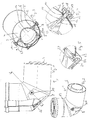
- FIGS. 1 to 5 is shown in partially sectioned illustrations and detailed drawings an arcuate designed combined exhaust / combustion air pipe system 1 for heating systems.
- the pipe system comprises a here made of metal, in particular stainless steel formed outer tube 2, in the coaxial with a smaller diameter exhibiting, designed as a plastic injection molded part of the exhaust pipe 3 is added.
- the lateral surface 4 of the exhaust pipe 3 is radially spaced from the inner peripheral surface 5 of the outer tube 2, so that outer tube 2 and exhaust pipe 3 define an annular combustion air duct 6 (fresh air duct).
- a closure lid 8 designed as a sheet metal lid, are integrally formed on the outer tube 2 formed with this radial extensions 9, which are supported on the inner circumference of the outer tube 2, with an end face annular surface 10 which surrounds a receiving opening 11 extending in the radial direction.
- the receiving openings 11 are each used for screw-receiving a metallic pin member 12, which are screwed with a thread formed as a tapping screw thread 13 in the before the screwing innengwindeschreib receiving opening. Both bolt parts 12 are located on a common axis 14.
- the bolt parts 12 each pass through a passage opening 15 in the outer tube 2 and are supported from radially outward radially inward with a shoulder 16 formed by an annular shoulder on the outer tube 2 and clamp it between the respective shoulder 16 and the associated radial extension 9.
- the bolt parts are radially outwardly provided with a drive 26.
- the pin members 12 each have a laterally open recess 17 in the closure lid 8, wherein the pin members 12 is provided in the region outside of the recess 17 with an external thread 18, with a trained as an internal thread nut fixing member 19 is screwed.
- the fixing member 19 is supported on the outside of the closure lid 8 and thus clamps this against the closure cover 8. By loosening the fixing member 19, the closure lid 8 can be detached.
- the fixing parts 19 are provided on the outer circumference with a knurling in order to operate them by hand can.
- the closure lid 8 not only closes a control opening 20 in the outer tube, but also serves as a backup for a preferably made of plastic exhaust pipe cover 21 which is sealingly received in an associated, molded pipe socket 22 of the exhaust pipe.
- a ring seal 24 formed as an O-ring seal is provided in a circumferential annular groove 23 of the exhaust pipe cover 21 and is supported in the radial direction on the pipe socket 22.
Landscapes
- Engineering & Computer Science (AREA)
- General Engineering & Computer Science (AREA)
- Mechanical Engineering (AREA)
- Exhaust Silencers (AREA)
- Housings, Intake/Discharge, And Installation Of Fluid Heaters (AREA)
- Chimneys And Flues (AREA)
- Rigid Pipes And Flexible Pipes (AREA)
Abstract
Description
Die Erfindung betrifft ein kombiniertes Abgas-/Verbrennungsluft-Rohrsystem gemäß dem Oberbegriff des Anspruchs 1, umfassend zwei, insbesondere koaxial ineinander verschachtelte Rohre, nämlich ein, bevorzugt metallisches Außenrohr und ein innerhalb des Außenrohrs verlaufendes, insbesondere aus Kunststoff ausgebildetes, Abgasrohr, wobei zwischen Außenrohr und Abgasrohr ein Verbrennungsluftkanal (Frischluftkanal) zur Zuführung von Verbrennungsluft zum Heizungsbrenner gebildet ist. Das Abgas verläuft hierzu gegenläufig zur Frischluft durch das Abgasrohr nach außen.The invention relates to a combined exhaust / combustion air pipe system according to the preamble of claim 1, comprising two, in particular coaxially nested tubes, namely a, preferably metallic outer tube and extending within the outer tube, in particular formed of plastic, exhaust pipe, wherein between the outer tube and exhaust pipe, a combustion air duct (fresh air duct) is formed for supplying combustion air to the heating burner. The exhaust gas runs counter to the fresh air through the exhaust pipe to the outside.
Aus der
Aus der
Ausgehend von dem vorgenannten Stand der Technik liegt der Erfindung die Aufgabe zugrunde ein hinsichtlich einer erleichterten Montage verbessertes kombiniertes Abgas-/Verbrennungsluft-Rohrsystem, insbesondere für Heizungsanlagen anzugeben.Based on the aforementioned prior art, the invention is based on the object with respect to a simplified assembly to provide improved combined exhaust / combustion air pipe system, in particular for heating systems.
Diese Aufgabe wird mit den Merkmalen des Anspruchs 1 gelöst. Vorteilhafte Weiterbildungen der Erfindung sind in den Unteransprüchen angegeben. In den Rahmen der Erfindung fallen sämtliche Kombinationen aus zumindest zwei von in der Beschreibung, den Ansprüche und/oder den Figuren offenbarten Merkmalen.This object is achieved with the features of claim 1. Advantageous developments of the invention are specified in the subclaims. All combinations of at least two features disclosed in the description, the claims and / or the figures fall within the scope of the invention.
Der Erfindung liegt der Gedanke zugrunde, kombinierte Fixiermittel zur gleichzeitigen axialen und radialen Sicherung des Außenrohrs und des Abgasrohrs relativ zueinander sowie zur Fixierung des Verschlussdeckels am Außenrohr vorzusehen. Erfindungsgemäß wird dies durch mindestens einen am Abgasrohr vorgesehen, insbesondere angeformten Radialfortsatz erreicht, an welchem ein Bolzenteil festgelegt ist, welches eine dem Bolzenteil zugeordnete und vorzugsweise radial mit dem Radialfortsatz fluchtende Durchgangsöffnung im Außenrohr durchsetzt, derart, dass an dem Bolzenteil ein Fixierteil zur lösbaren Fixierung des Verschlussdeckels am Außenrohr anordnenbar ist. Anders ausgedrückt ist am Abgasrohr mindestens ein Radialfortsatz vorgesehen, vorzugsweise einstückig mit dem insbesondere als Spritzgussteil ausgebildeten Abgasrohr ausgebildet, der geeignet und bestimmt ist, um daran ein, insbesondere aus Metall ausgebildetes Bolzenteil festzulegen, wobei noch weiter bevorzugt das Bolzenteil mit einem Gewinde, insbesondere einem Außengewinde, am Radialfortsatz, insbesondere in einer radialen Öffnung, verschraubt ist, wobei mittels des Radialfortsatzes der zur Ausbildung des Verbrennungsluftkanals notwendige Abstand zwischen dem inneren Abgasrohr und dem äußeren, vorzugsweise metallischen Außenrohr eingehalten wird. Als besonders zweckmäßig hat es sich erwiesen, wenn sich der Radialfortsatz an der Innumfangsfläche des Außenrohres, insbesondere in einem Randbereich der Durchgangsöffnung abstützt, um so einen definierten Radialabstand zwischen Außenrohr und Abgasrohr einzuhalten. Das Bolzenteil, welches bevorzugt mit dem Radialfortsatz, vorzugsweise im Radialfortsatz, verschraubt ist, wirkt mit einem Fixierteil zur lösbaren Fixierung des Verschlussdeckels zusammen, wobei das Fixierteil bevorzugt mit dem Bolzenteil verschraubbar ist, um den Verschlussdeckel verklemmend am Außenrohr festzulegen. Ganz besonders bevorzugt sind mindestens zwei derartige Radialfortsatz-Bolzenteil-Fixierteil-Kombinationen zur Fixierung des Verschlussdeckels an zwei in Umfangsrichtung voneinander beabstandeten Stellen vorgesehen. Durch die Erfindung wird durch eine kombinierte Maßnahme eine radiale und axiale Fixierung der beiden Rohre aneinander sichergestellt und gleichzeitig auf einfache und komfortable Weise eine Fixierung des Verschlussdeckels am Außenrohr ermöglicht. Bei Bedarf kann auf zusätzliche Verbindungselemente, wie diese in der
Wie eingangs bereits erwähnt, hat es sich als besonders vorteilhaft erwiesen, ein metallisches Bolzenteil mit einem Kunststoff-Abgasrohr, insbesondere einem als Kunststoffspritzgussteil ausgebildeten Abgasrohr zu kombinieren, wobei das Bolzenteil bevorzugt mit einem Gewinde, insbesondere einem Außengewinde, mit dem Radialfortsatz verschraubt ist. Zu Montagezwecken ist es vorteilhaft, das Außengewinde des Bolzenteils als kostengünstig realisierbares Blechschraubenaussengwinde auszubilden, da in diesem Fall auf eine Vorformung eines Gegengewindes, insbesondere eines Innengewindes im Radialfortsatz verzichtet werden kann. Bevorzugt weist der Radialfortsatz eine in radialer Richtung verlaufende Aufnahmeöffnung zum Einschrauben des Bolzenteils auf.As already mentioned, it has proved to be particularly advantageous to combine a metallic bolt part with a plastic exhaust pipe, in particular designed as a plastic injection molded part exhaust pipe, wherein the bolt part is preferably screwed with a thread, in particular an external thread, with the radial extension. For assembly purposes, it is advantageous to form the external thread of the bolt part as economically feasible Blechschraubenssengengine, since in this case can be dispensed with a preforming of a counter-thread, in particular an internal thread in the radial extension. Preferably, the radial extension on a running in the radial direction receiving opening for screwing the bolt part.
Als besonders zweckmäßig hat es sich herausgestellt, das Fixierteil zur lösbaren Fixierung des Verschlussdeckels als Innengewindemutter auszubilden, die auf ein korrespondierendes Außengewinde des Bolzenteils aufgeschraubt ist, wobei vorgenanntes Außengewinde aus der Durchgangsöffnung im vorzugsweise metallischen Außenrohr hinausragt.As it has been found to be particularly expedient to form the fixing part for releasably fixing the closure cap as an internally threaded nut which is screwed onto a corresponding external thread of the bolt part, wherein said external thread protrudes from the through hole in the preferably metallic outer tube.
Besonders bevorzugt weist das Bolzenteil in einem außerhalb des Außenrohres angeordneten Abschnitt einen in Richtung Außenrohr weisenden Absatz, insbesondere eine Ringschulter und/oder einen Umfangsbund auf, damit sich das Bolzenteil hiermit in radialer Richtung von außen an der Mantelfläche des Außenrohres oder einer dort vorgesehenen Unterlegscheibe abstützen kann. Bevorzugt kann auf diese Weise das Außenrohr radial eingeklemmt werden zwischen diesem äußeren Absatz und einer entsprechenden Gegenfläche des Radialfortsatzes, wobei es sich bei letztgenannter Fläche vorzugsweise um eine Ringfläche handelt, die eine Aufnahmeöffnung für das Bolzenteil stirnseitig umgibt.Particularly preferably, the bolt part in a section arranged outside the outer tube has a pointing in the direction of the outer tube shoulder, in particular an annular shoulder and / or a circumferential collar, so that the bolt part hereby supported in the radial direction from the outside on the outer surface of the outer tube or a washer provided there can. Preferably, in this way, the outer tube can be radially clamped between this outer shoulder and a corresponding counter surface of the radial extension, wherein the latter surface is preferably an annular surface which surrounds a receiving opening for the bolt part on the end side.
Zur optimalen Fixierung des Verschlussdeckels hat es sich als vorteilhaft herausgestellt, wenn das Bolzenteil mit einem außerhalb des Außenrohrs gelegenen Abschnitt eine Aussparung im Verschlussdeckel radial durchsetzt, wobei es zu einer erleichterten Montage und Demontage des Deckels vorteilhaft ist, wenn diese Aussparung seitlich offen ist, um ein seitliches Einschnappen des Verschlussdeckels um das Bolzenteil auch bei nicht vollständig entferntem Fixierteil zu ermöglichen.For optimal fixation of the closure cap, it has been found to be advantageous if the bolt part penetrates radially through a recess in the closure cap with a portion located outside of the outer tube, wherein it is advantageous to facilitate assembly and disassembly of the lid when this recess is open to the side a lateral snapping the closure cover to allow the bolt member even if not completely removed fixing.
Wie eingangs erwähnt, hat es sich als besonders vorteilhaft herausgestellt, mindestens zwei, vorzugsweise ausschließlich zwei, Radialfortsatz-Bolzenteil-Fixierteil-Kombinationen vorzusehen, insbesondere weiterbildungsgemäß derart, dass die Bolzenteile auf einer gemeinsamen gedachten Achse liegen, so dass eine Art Schwenkachse definiert wird, um die das Abgasrohr innerhalb des Außenrohrs verkippen kann, zumindest bis keine (zusätzlichen), beispielsweise in der
Bevorzugt ist dem Verschlussdeckel zum Verschließen des Außenrohres ein Abgasrohrdeckel im Abgasrohr vorgesehen, der gelöst werden kann, nachdem der Verschlussdeckel durch Lösen des mindestens einen Fixierteils abgelöst wurde. Besonders zweckmäßig ist es nun, wenn sich der Verschlussdeckel auf dem Abgasrohrdeckel abstützt, so dass dieser in radialer Richtung gesichert ist und somit ein möglicher Überdruck im Abgasrohr nicht zu einem unbeabsichtigten Herauslösen des Abgasrohrdeckels führen kann.Preferably, the closure lid for closing the outer tube, an exhaust pipe cover is provided in the exhaust pipe, which can be solved after the closure lid has been detached by loosening the at least one fixing part. It is particularly useful if the closure lid is supported on the exhaust pipe cover so that it is secured in the radial direction and thus a possible overpressure in the exhaust pipe can not lead to unintentional detachment of the exhaust pipe cover.
Ganz besonders bevorzugt ist das Rohrsystem als Rohrbogensystem ausgebildet, wobei Abgasrohr und Außenrohr jeweils mindestens einen Rohrbogen umfassen. Es ist jedoch auch eine gerade Ausführung des Abgasrohrs mit einem geraden Abgasrohr und einem geraden Außenrohr realisierbar. Besonders zweckmäßig ist es, wenn das Abgasrohr das Außenrohr an einem Rohrende, insbesondere um mindestens 0,5cm überragt.Most preferably, the pipe system is designed as a pipe bend system, wherein exhaust pipe and outer tube each comprise at least one pipe bend. However, it is also a straight design of the exhaust pipe with a straight exhaust pipe and a straight outer tube feasible. It is particularly expedient if the exhaust pipe projects beyond the outer pipe at a pipe end, in particular by at least 0.5 cm.
Weitere Vorteile, Merkmale und Einzelheiten der Erfindung ergeben sich aus der nachfolgenden Beschreibung bevorzugter Ausführungsbeispiele sowie anhand der Zeichnungen.Further advantages, features and details of the invention will become apparent from the following description of preferred embodiments and from the drawings.
Diese zeigen in:
- Fig. 1
- eine teilgeschnittene Darstellung eines Rohrsystems,
- Fig. 2
- eine perspektivisch Außenansicht des Rohrsystems gemäß
Fig. 1 , - Fig. 3
- eine Schnittansicht entlang der Schnittlinie A-A gemäß
Fig. 1 , - Fig. 4
- ein Detail X aus
Fig. 3 , und - Fig. 5
- ein Detail Y aus
Fig. 3 .
- Fig. 1
- a partially sectioned representation of a pipe system,
- Fig. 2
- a perspective outside view of the pipe system according to
Fig. 1 . - Fig. 3
- a sectional view along the section line AA according to
Fig. 1 . - Fig. 4
- a detail X out
Fig. 3 , and - Fig. 5
- a detail Y out
Fig. 3 ,
In den Figuren sind gleiche Elemente und Elemente mit der gleichen Funktion mit den gleichen Bezugszeichen gekennzeichnet.In the figures, like elements and elements having the same function are denoted by the same reference numerals.
In den
Wie sich aus
Zur gleichzeitigen axialen und radialen Sicherung von Außenrohr 2 und Abgasrohr 3 relativ zueinander und zur Fixierung eines im Folgenden noch zu erläuternden, als Blechdeckel ausgeführten Verschlussdeckels 8, sind an dem Außenrohr 2 einteilig mit diesem ausgebildete Radialfortsätze 9 angeformt, die sich am Innenumfang des Außenrohrs 2 abstützen und zwar mit einer stirnseitigen Ringfläche 10, die eine in radialer Richtung verlaufende Aufnahmeöffnung 11 umgibt. Zur Verstärkung der Radialfortsätze 9 sind an diesen seitliche Streben 25 angeformt, die sich nach radial außen verjüngen. Die Aufnahmeöffnungen 11 dienen jeweils zur verschraubenden Aufnahme eines metallischen Bolzenteils 12, welches mit einem als Blechschraubengewinde ausgebildeten Gewinde 13 in die vor dem Verschraubvorgang innengwindefreie Aufnahmeöffnung eingeschraubt sind. Beide Bolzenteile 12 befinden sich auf einer gemeinsamen Achse 14.For the simultaneous axial and radial securing of the
Die Bolzenteile 12 durchsetzen jeweils eine Durchgangsöffnung 15 im Außenrohr 2 und stützen sich von radial außen nach radial innen mit einem von einer Ringschulter gebildeten Absatz 16 am Außenrohr 2 ab und klemmen dieses zwischen dem jeweiligen Absatz 16 und dem zugehörigen Radialfortsatz 9. Zum Einschrauben der Bolzenteile 12 in die zugehörigen Aufnahmeöffnungen 11 sind die Bolzenteile radial außen mit einem Antrieb 26 versehen.The
Gleichzeitig durchsetzen die Bolzenteile 12 jeweils eine seitlich offene Aussparung 17 im Verschlussdeckel 8, wobei die Bolzenteile 12 in dem außerhalb der Aussparung 17 gelegenen Bereich mit einem Außengewinde 18 versehen ist, mit dem ein als Innengewindemutter ausgebildetes Fixierteil 19 verschraubt ist. Das Fixierteil 19 stützt sich außen am Verschlussdeckel 8 ab und klemmt diesen somit gegen den Verschlussdeckel 8. Durch Lösen des Fixierteils 19 kann der Verschlussdeckel 8 abgelöst werden.At the same time enforce the
Wie sich insbesondere aus den
Der Verschlussdeckel 8 verschließt nicht nur eine Kontrollöffnung 20 im Außenrohr, sondern dient gleichzeitig als Sicherung für einen vorzugsweise aus Kunststoff ausgebildeten Abgasrohrdeckel 21, der in einem zugeordneten, angeformten Rohrstutzen 22 des Abgasrohrs dichtend aufgenommen ist. Zur Herstellung einer dichten Verbindung ist in einer umlaufenden Ringnut 23 des Abgasrohrdeckels 21 eine als O-Ringdichtung ausgebildete Ringdichtung 24 vorgesehen, die sich in radialer Richtung am Rohrstutzen 22 abstützt.
Claims (13)
dadurch gekennzeichnet,
dass an dem Radialfortsatz (9) ein Bolzenteil (12) festgelegt ist, das eine diesem zugeordnete Durchgangsöffnung (15) im Außenrohr (2) durchsetzt und dass an dem Bolzenteil (12) ein Fixierteil (19) zur lösbaren Fixierung des Verschlussdeckels (8) am Außenrohr (2) vorgesehen ist.Combined exhaust / combustion air piping system comprising an outer outer tube (2) having a control port (20) and an exhaust tube (3) disposed in the outer tube (2), an exhaust tube lateral surface radially extending from an inner peripheral surface (5) of the outer tube (2) is radially spaced such that between the exhaust pipe (3) and outer tube (2) an annular combustion air duct (6) is formed and wherein the control opening (20) is associated with a releasably arranged closure cover (8), wherein the exhaust pipe (3) has a radial extension ( 9) is provided for the radial spacing of the exhaust pipe jacket surface from the inner peripheral surface (5) of the outer pipe (2),
characterized,
in that a bolt part (12) is fixed to the radial extension (9), passes through a passage opening (15) in the outer tube (2) and that a fixing part (19) for releasably fixing the closure cover (8) is attached to the bolt part (12). is provided on the outer tube (2).
dadurch gekennzeichnet,
dass das, bevorzugt metallische, Bolzenteil (12) mit einem, insbesondere als Außengewinde (18), bevorzugt als Blechschraubenaußengewinde, ausgebildeten Gewinde mit dem Radialfortsatz (9) verschraubt ist.Pipe system according to claim 1,
characterized,
in that the, preferably metallic, bolt part (12) is screwed to the radial extension (9) with a thread formed, in particular as an external thread (18), preferably as a tapping screw outer thread.
dadurch gekennzeichnet,
dass das Bolzenteil (12) in eine radiale Innengewindeöffnung des Radialfortsatzes (9) eingeschraubt ist.Pipe system according to claim 2,
characterized,
that the bolt part (12) is screwed into a radially inner threaded opening of the radial extension (9).
dadurch gekennzeichnet,
dass das Fixierteil (19) als Innengewindemutter ausgebildet ist, die auf ein korrespondierendes Außengewinde (18) des Bolzenteils (12) aufgeschraubt ist und den Verschlussdeckel (8) gegen das Außenrohr (2) presst.Pipe system according to one of the preceding claims,
characterized,
in that the fixing part (19) is designed as an internally threaded nut, which is screwed onto a corresponding external thread (18) of the bolt part (12) and presses the closure cover (8) against the outer tube (2).
dadurch gekennzeichnet,
dass sich das Bolzenteil (12) mit einem Absatz (16), insbesondere einer Ringschulter, von außen auf der Mantelfläche (4) des Außenrohres (2) oder einer dort vorgesehenen Unterlegscheibe abstützt.Pipe system according to one of the preceding claims,
characterized,
that the bolt part (12) is supported with a shoulder (16), in particular an annular shoulder, from outside on the lateral surface (4) of the outer tube (2) or a washer provided there.
dadurch gekennzeichnet,
dass das Bolzenteil (12) eine, insbesondere seitlich offene, Aussparung (17) im Verschlussdeckel (8) durchsetzt.Pipe system according to one of the preceding claims,
characterized,
in that the bolt part (12) passes through a recess (17), in particular laterally open, in the closure cover (8).
dadurch gekennzeichnet,
dass der Verschlussdeckel (8) mit zwei auf einer gedachten Achse (14) liegenden Bolzenteilen (12) und Fixierteilen (19) an zwei diesen zugeordneten Radialfortsätzen fixiert ist.Pipe system according to one of the preceding claims,
characterized,
in that the closure lid (8) is fixed to two bolt parts (12) and fixing parts (19) lying on an imaginary axis (14) on two radial extensions associated therewith.
dadurch gekennzeichnet,
dass der Verschlussdeckel (8) radial außerhalb eines dichtend eine Abgasrohröffnung verschließenden Abgasrohrdeckels (21) angeordnet ist, vorzugsweise sich als Sicherungsteil auf diesem abstützt.Pipe system according to one of the preceding claims,
characterized,
in that the closure lid (8) is arranged radially outside of an exhaust gas pipe cover (21) sealing off an exhaust gas pipe opening, preferably being supported on it as a securing part.
dadurch gekennzeichnet,
dass Abgasrohr (3) und Außenrohr (2) als Rohrbögen ausgebildet sind, bevorzugt dass das Abgasrohr (3) das Außenrohr (2) an einem Rohrende (7) überragt, oder das Abgasrohr (3) und Außenrohr (2) als gerade Rohrstücke ausgebildet sind.Pipe system according to one of the preceding claims,
characterized,
the exhaust pipe (3) and the outer pipe (2) are formed as pipe bends, preferably that the exhaust pipe (3) projects beyond the outer pipe (2) at a pipe end (7), or the exhaust pipe (3) and outer pipe (2) are formed as straight pipe pieces are.
dadurch gekennzeichnet,
dass der Radialfortsatz (9) an das Abgasrohr (3) angeformt ist.Pipe system according to one of the preceding claims,
characterized,
that the radial extension (9) is integrally formed on the exhaust pipe (3).
dadurch gekennzeichnet,
dass das Außenrohr metallisch ist.Pipe system according to one of the preceding claims,
characterized,
that the outer tube is metallic.
dadurch gekennzeichnet,
dass das Abgasrohr (3) aus Kunststoff besteht.Pipe system according to one of the preceding claims,
characterized,
that the exhaust pipe (3) consists of plastic.
Applications Claiming Priority (1)
| Application Number | Priority Date | Filing Date | Title |
|---|---|---|---|
| DE102012106707A DE102012106707B3 (en) | 2012-07-24 | 2012-07-24 | Flue gas / combustion air pipe system |
Publications (3)
| Publication Number | Publication Date |
|---|---|
| EP2690334A2 true EP2690334A2 (en) | 2014-01-29 |
| EP2690334A3 EP2690334A3 (en) | 2015-08-05 |
| EP2690334B1 EP2690334B1 (en) | 2016-06-01 |
Family
ID=48190271
Family Applications (1)
| Application Number | Title | Priority Date | Filing Date |
|---|---|---|---|
| EP13165539.1A Active EP2690334B1 (en) | 2012-07-24 | 2013-04-26 | Flue gas/combustion air pipe system |
Country Status (2)
| Country | Link |
|---|---|
| EP (1) | EP2690334B1 (en) |
| DE (1) | DE102012106707B3 (en) |
Families Citing this family (1)
| Publication number | Priority date | Publication date | Assignee | Title |
|---|---|---|---|---|
| DE102016101460A1 (en) * | 2016-01-27 | 2017-07-27 | Dieter Bächle | Plastic socket pipe and heating system |
Citations (2)
| Publication number | Priority date | Publication date | Assignee | Title |
|---|---|---|---|---|
| DE102004019246B3 (en) | 2003-08-29 | 2005-05-25 | Dieter Bächle | Pipe system carrying especially gaseous medium has in larger diameter outer pipe a radially extending connecting element formed as closed ring from extruded wire with ends permanently interconnected by welding |
| DE102008051271A1 (en) | 2008-01-21 | 2009-07-30 | Bächle, Dieter | Pipe unit made of interconnected pipe sections |
Family Cites Families (1)
| Publication number | Priority date | Publication date | Assignee | Title |
|---|---|---|---|---|
| DE10159564C1 (en) * | 2001-12-05 | 2003-06-26 | Ct Therm Abgassystemtechnik Gm | Device for connecting two sections of an air-exhaust pipe |
-
2012
- 2012-07-24 DE DE102012106707A patent/DE102012106707B3/en not_active Withdrawn - After Issue
-
2013
- 2013-04-26 EP EP13165539.1A patent/EP2690334B1/en active Active
Patent Citations (2)
| Publication number | Priority date | Publication date | Assignee | Title |
|---|---|---|---|---|
| DE102004019246B3 (en) | 2003-08-29 | 2005-05-25 | Dieter Bächle | Pipe system carrying especially gaseous medium has in larger diameter outer pipe a radially extending connecting element formed as closed ring from extruded wire with ends permanently interconnected by welding |
| DE102008051271A1 (en) | 2008-01-21 | 2009-07-30 | Bächle, Dieter | Pipe unit made of interconnected pipe sections |
Also Published As
| Publication number | Publication date |
|---|---|
| EP2690334B1 (en) | 2016-06-01 |
| DE102012106707B3 (en) | 2013-11-07 |
| EP2690334A3 (en) | 2015-08-05 |
Similar Documents
| Publication | Publication Date | Title |
|---|---|---|
| DE102010061067B4 (en) | Device for fixing a cable to a cable outlet connection | |
| DE102015115890B4 (en) | Arrangement for producing a pipe connection | |
| EP2369211B1 (en) | Device for a sealed feedthrough of long moulded parts | |
| EP3379129B1 (en) | Connector | |
| WO2012010168A2 (en) | Device for fixing a cable to a cable outlet connector | |
| WO2008110235A1 (en) | Cable screw connection having a counter sleeve or union nut | |
| WO2012041303A9 (en) | Helical strain relief element | |
| EP2735779A1 (en) | Device for the sealed feedthrough of long moulded parts | |
| DE202017100423U1 (en) | Hose connection arrangement, use of a hose connection arrangement and sanitary fitting | |
| DE102017101566B3 (en) | Hose connection arrangement, use of a hose connection arrangement and sanitary fitting | |
| EP2278204B1 (en) | Screw connection for corrugated pipe | |
| DE102004025466B4 (en) | cap | |
| EP3037150B1 (en) | Filter device | |
| EP2690334B1 (en) | Flue gas/combustion air pipe system | |
| DE102010032694B3 (en) | Cooling tower water distribution | |
| EP1795792A2 (en) | Pipe clamp | |
| EP3670766B1 (en) | Connection set for a drinking or domestic water installation | |
| DE10351979B4 (en) | tube element | |
| DE202018101002U1 (en) | Pipe connection and pipe connection | |
| DE102013001124B3 (en) | Hose connection arrangement for use at wall for producing path for fluid through wall, has hose fitting integrally formed with blind rivet nut, and arranged at end of threaded section, where end faces away from deforming region | |
| DE10326300A1 (en) | Sanitary hose with rotatable coupling for a connector | |
| EP3940158A1 (en) | Sanitary fitting having a quick fitting nut | |
| EP2559926A1 (en) | Safety valve | |
| WO2019141837A1 (en) | Elbow screw joint system | |
| DE3106985A1 (en) | Hose attachment, especially for high-pressure hoses |
Legal Events
| Date | Code | Title | Description |
|---|---|---|---|
| PUAI | Public reference made under article 153(3) epc to a published international application that has entered the european phase |
Free format text: ORIGINAL CODE: 0009012 |
|
| AK | Designated contracting states |
Kind code of ref document: A2 Designated state(s): AL AT BE BG CH CY CZ DE DK EE ES FI FR GB GR HR HU IE IS IT LI LT LU LV MC MK MT NL NO PL PT RO RS SE SI SK SM TR |
|
| AX | Request for extension of the european patent |
Extension state: BA ME |
|
| PUAL | Search report despatched |
Free format text: ORIGINAL CODE: 0009013 |
|
| AK | Designated contracting states |
Kind code of ref document: A3 Designated state(s): AL AT BE BG CH CY CZ DE DK EE ES FI FR GB GR HR HU IE IS IT LI LT LU LV MC MK MT NL NO PL PT RO RS SE SI SK SM TR |
|
| AX | Request for extension of the european patent |
Extension state: BA ME |
|
| RIC1 | Information provided on ipc code assigned before grant |
Ipc: F23J 13/02 20060101ALI20150630BHEP Ipc: F16L 41/08 20060101ALI20150630BHEP Ipc: F16L 9/18 20060101ALI20150630BHEP Ipc: F16L 45/00 20060101ALI20150630BHEP Ipc: F16L 7/00 20060101ALI20150630BHEP Ipc: F16L 41/00 20060101ALI20150630BHEP Ipc: F23D 14/66 20060101ALI20150630BHEP Ipc: F23J 13/04 20060101ALI20150630BHEP Ipc: F23J 13/08 20060101ALI20150630BHEP Ipc: F16L 9/19 20060101AFI20150630BHEP |
|
| 17P | Request for examination filed |
Effective date: 20150824 |
|
| RBV | Designated contracting states (corrected) |
Designated state(s): AL AT BE BG CH CY CZ DE DK EE ES FI FR GB GR HR HU IE IS IT LI LT LU LV MC MK MT NL NO PL PT RO RS SE SI SK SM TR |
|
| GRAP | Despatch of communication of intention to grant a patent |
Free format text: ORIGINAL CODE: EPIDOSNIGR1 |
|
| RIC1 | Information provided on ipc code assigned before grant |
Ipc: F16L 41/00 20060101ALI20151009BHEP Ipc: F16L 7/00 20060101ALI20151009BHEP Ipc: F16L 9/18 20060101ALI20151009BHEP Ipc: F23J 13/02 20060101ALI20151009BHEP Ipc: F16L 9/19 20060101AFI20151009BHEP Ipc: F16L 41/08 20060101ALI20151009BHEP Ipc: F23D 14/66 20060101ALI20151009BHEP Ipc: F16L 45/00 20060101ALI20151009BHEP Ipc: F23J 13/04 20060101ALI20151009BHEP Ipc: F23J 13/08 20060101ALI20151009BHEP |
|
| INTG | Intention to grant announced |
Effective date: 20151113 |
|
| GRAS | Grant fee paid |
Free format text: ORIGINAL CODE: EPIDOSNIGR3 |
|
| GRAA | (expected) grant |
Free format text: ORIGINAL CODE: 0009210 |
|
| AK | Designated contracting states |
Kind code of ref document: B1 Designated state(s): AL AT BE BG CH CY CZ DE DK EE ES FI FR GB GR HR HU IE IS IT LI LT LU LV MC MK MT NL NO PL PT RO RS SE SI SK SM TR |
|
| REG | Reference to a national code |
Ref country code: GB Ref legal event code: FG4D Free format text: NOT ENGLISH |
|
| REG | Reference to a national code |
Ref country code: CH Ref legal event code: EP Ref country code: AT Ref legal event code: REF Ref document number: 804093 Country of ref document: AT Kind code of ref document: T Effective date: 20160615 |
|
| REG | Reference to a national code |
Ref country code: IE Ref legal event code: FG4D Free format text: LANGUAGE OF EP DOCUMENT: GERMAN |
|
| REG | Reference to a national code |
Ref country code: DE Ref legal event code: R096 Ref document number: 502013003244 Country of ref document: DE |
|
| REG | Reference to a national code |
Ref country code: LT Ref legal event code: MG4D |
|
| REG | Reference to a national code |
Ref country code: CH Ref legal event code: NV Representative=s name: BODENSEEPATENT GMBH, CH |
|
| REG | Reference to a national code |
Ref country code: NL Ref legal event code: MP Effective date: 20160601 |
|
| PG25 | Lapsed in a contracting state [announced via postgrant information from national office to epo] |
Ref country code: NO Free format text: LAPSE BECAUSE OF FAILURE TO SUBMIT A TRANSLATION OF THE DESCRIPTION OR TO PAY THE FEE WITHIN THE PRESCRIBED TIME-LIMIT Effective date: 20160901 Ref country code: LT Free format text: LAPSE BECAUSE OF FAILURE TO SUBMIT A TRANSLATION OF THE DESCRIPTION OR TO PAY THE FEE WITHIN THE PRESCRIBED TIME-LIMIT Effective date: 20160601 Ref country code: FI Free format text: LAPSE BECAUSE OF FAILURE TO SUBMIT A TRANSLATION OF THE DESCRIPTION OR TO PAY THE FEE WITHIN THE PRESCRIBED TIME-LIMIT Effective date: 20160601 |
|
| PG25 | Lapsed in a contracting state [announced via postgrant information from national office to epo] |
Ref country code: LV Free format text: LAPSE BECAUSE OF FAILURE TO SUBMIT A TRANSLATION OF THE DESCRIPTION OR TO PAY THE FEE WITHIN THE PRESCRIBED TIME-LIMIT Effective date: 20160601 Ref country code: NL Free format text: LAPSE BECAUSE OF FAILURE TO SUBMIT A TRANSLATION OF THE DESCRIPTION OR TO PAY THE FEE WITHIN THE PRESCRIBED TIME-LIMIT Effective date: 20160601 Ref country code: HR Free format text: LAPSE BECAUSE OF FAILURE TO SUBMIT A TRANSLATION OF THE DESCRIPTION OR TO PAY THE FEE WITHIN THE PRESCRIBED TIME-LIMIT Effective date: 20160601 Ref country code: RS Free format text: LAPSE BECAUSE OF FAILURE TO SUBMIT A TRANSLATION OF THE DESCRIPTION OR TO PAY THE FEE WITHIN THE PRESCRIBED TIME-LIMIT Effective date: 20160601 Ref country code: SE Free format text: LAPSE BECAUSE OF FAILURE TO SUBMIT A TRANSLATION OF THE DESCRIPTION OR TO PAY THE FEE WITHIN THE PRESCRIBED TIME-LIMIT Effective date: 20160601 Ref country code: GR Free format text: LAPSE BECAUSE OF FAILURE TO SUBMIT A TRANSLATION OF THE DESCRIPTION OR TO PAY THE FEE WITHIN THE PRESCRIBED TIME-LIMIT Effective date: 20160902 Ref country code: ES Free format text: LAPSE BECAUSE OF FAILURE TO SUBMIT A TRANSLATION OF THE DESCRIPTION OR TO PAY THE FEE WITHIN THE PRESCRIBED TIME-LIMIT Effective date: 20160601 |
|
| PG25 | Lapsed in a contracting state [announced via postgrant information from national office to epo] |
Ref country code: CZ Free format text: LAPSE BECAUSE OF FAILURE TO SUBMIT A TRANSLATION OF THE DESCRIPTION OR TO PAY THE FEE WITHIN THE PRESCRIBED TIME-LIMIT Effective date: 20160601 Ref country code: IS Free format text: LAPSE BECAUSE OF FAILURE TO SUBMIT A TRANSLATION OF THE DESCRIPTION OR TO PAY THE FEE WITHIN THE PRESCRIBED TIME-LIMIT Effective date: 20161001 Ref country code: RO Free format text: LAPSE BECAUSE OF FAILURE TO SUBMIT A TRANSLATION OF THE DESCRIPTION OR TO PAY THE FEE WITHIN THE PRESCRIBED TIME-LIMIT Effective date: 20160601 Ref country code: SK Free format text: LAPSE BECAUSE OF FAILURE TO SUBMIT A TRANSLATION OF THE DESCRIPTION OR TO PAY THE FEE WITHIN THE PRESCRIBED TIME-LIMIT Effective date: 20160601 Ref country code: EE Free format text: LAPSE BECAUSE OF FAILURE TO SUBMIT A TRANSLATION OF THE DESCRIPTION OR TO PAY THE FEE WITHIN THE PRESCRIBED TIME-LIMIT Effective date: 20160601 Ref country code: IT Free format text: LAPSE BECAUSE OF FAILURE TO SUBMIT A TRANSLATION OF THE DESCRIPTION OR TO PAY THE FEE WITHIN THE PRESCRIBED TIME-LIMIT Effective date: 20160601 |
|
| PG25 | Lapsed in a contracting state [announced via postgrant information from national office to epo] |
Ref country code: PT Free format text: LAPSE BECAUSE OF FAILURE TO SUBMIT A TRANSLATION OF THE DESCRIPTION OR TO PAY THE FEE WITHIN THE PRESCRIBED TIME-LIMIT Effective date: 20161003 Ref country code: SM Free format text: LAPSE BECAUSE OF FAILURE TO SUBMIT A TRANSLATION OF THE DESCRIPTION OR TO PAY THE FEE WITHIN THE PRESCRIBED TIME-LIMIT Effective date: 20160601 Ref country code: PL Free format text: LAPSE BECAUSE OF FAILURE TO SUBMIT A TRANSLATION OF THE DESCRIPTION OR TO PAY THE FEE WITHIN THE PRESCRIBED TIME-LIMIT Effective date: 20160601 |
|
| REG | Reference to a national code |
Ref country code: DE Ref legal event code: R097 Ref document number: 502013003244 Country of ref document: DE |
|
| PLBE | No opposition filed within time limit |
Free format text: ORIGINAL CODE: 0009261 |
|
| STAA | Information on the status of an ep patent application or granted ep patent |
Free format text: STATUS: NO OPPOSITION FILED WITHIN TIME LIMIT |
|
| 26N | No opposition filed |
Effective date: 20170302 |
|
| REG | Reference to a national code |
Ref country code: CH Ref legal event code: NV Representative=s name: BODENSEEPATENT PATENTANWAELTE BEHRMANN WAGNER , CH |
|
| PG25 | Lapsed in a contracting state [announced via postgrant information from national office to epo] |
Ref country code: DK Free format text: LAPSE BECAUSE OF FAILURE TO SUBMIT A TRANSLATION OF THE DESCRIPTION OR TO PAY THE FEE WITHIN THE PRESCRIBED TIME-LIMIT Effective date: 20160601 Ref country code: SI Free format text: LAPSE BECAUSE OF FAILURE TO SUBMIT A TRANSLATION OF THE DESCRIPTION OR TO PAY THE FEE WITHIN THE PRESCRIBED TIME-LIMIT Effective date: 20160601 |
|
| GBPC | Gb: european patent ceased through non-payment of renewal fee |
Effective date: 20170426 |
|
| REG | Reference to a national code |
Ref country code: IE Ref legal event code: MM4A |
|
| REG | Reference to a national code |
Ref country code: FR Ref legal event code: ST Effective date: 20171229 |
|
| PG25 | Lapsed in a contracting state [announced via postgrant information from national office to epo] |
Ref country code: FR Free format text: LAPSE BECAUSE OF NON-PAYMENT OF DUE FEES Effective date: 20170502 Ref country code: MC Free format text: LAPSE BECAUSE OF FAILURE TO SUBMIT A TRANSLATION OF THE DESCRIPTION OR TO PAY THE FEE WITHIN THE PRESCRIBED TIME-LIMIT Effective date: 20160601 |
|
| PG25 | Lapsed in a contracting state [announced via postgrant information from national office to epo] |
Ref country code: LU Free format text: LAPSE BECAUSE OF NON-PAYMENT OF DUE FEES Effective date: 20170426 Ref country code: GB Free format text: LAPSE BECAUSE OF NON-PAYMENT OF DUE FEES Effective date: 20170426 |
|
| REG | Reference to a national code |
Ref country code: BE Ref legal event code: MM Effective date: 20170430 |
|
| PG25 | Lapsed in a contracting state [announced via postgrant information from national office to epo] |
Ref country code: IE Free format text: LAPSE BECAUSE OF NON-PAYMENT OF DUE FEES Effective date: 20170426 |
|
| PG25 | Lapsed in a contracting state [announced via postgrant information from national office to epo] |
Ref country code: BE Free format text: LAPSE BECAUSE OF NON-PAYMENT OF DUE FEES Effective date: 20170430 |
|
| PG25 | Lapsed in a contracting state [announced via postgrant information from national office to epo] |
Ref country code: MT Free format text: LAPSE BECAUSE OF FAILURE TO SUBMIT A TRANSLATION OF THE DESCRIPTION OR TO PAY THE FEE WITHIN THE PRESCRIBED TIME-LIMIT Effective date: 20160601 |
|
| PG25 | Lapsed in a contracting state [announced via postgrant information from national office to epo] |
Ref country code: AL Free format text: LAPSE BECAUSE OF FAILURE TO SUBMIT A TRANSLATION OF THE DESCRIPTION OR TO PAY THE FEE WITHIN THE PRESCRIBED TIME-LIMIT Effective date: 20160601 |
|
| REG | Reference to a national code |
Ref country code: DE Ref legal event code: R084 Ref document number: 502013003244 Country of ref document: DE |
|
| PG25 | Lapsed in a contracting state [announced via postgrant information from national office to epo] |
Ref country code: HU Free format text: LAPSE BECAUSE OF FAILURE TO SUBMIT A TRANSLATION OF THE DESCRIPTION OR TO PAY THE FEE WITHIN THE PRESCRIBED TIME-LIMIT; INVALID AB INITIO Effective date: 20130426 |
|
| PG25 | Lapsed in a contracting state [announced via postgrant information from national office to epo] |
Ref country code: BG Free format text: LAPSE BECAUSE OF FAILURE TO SUBMIT A TRANSLATION OF THE DESCRIPTION OR TO PAY THE FEE WITHIN THE PRESCRIBED TIME-LIMIT Effective date: 20160601 |
|
| PG25 | Lapsed in a contracting state [announced via postgrant information from national office to epo] |
Ref country code: CY Free format text: LAPSE BECAUSE OF NON-PAYMENT OF DUE FEES Effective date: 20160601 |
|
| PG25 | Lapsed in a contracting state [announced via postgrant information from national office to epo] |
Ref country code: MK Free format text: LAPSE BECAUSE OF FAILURE TO SUBMIT A TRANSLATION OF THE DESCRIPTION OR TO PAY THE FEE WITHIN THE PRESCRIBED TIME-LIMIT Effective date: 20160601 |
|
| PG25 | Lapsed in a contracting state [announced via postgrant information from national office to epo] |
Ref country code: TR Free format text: LAPSE BECAUSE OF FAILURE TO SUBMIT A TRANSLATION OF THE DESCRIPTION OR TO PAY THE FEE WITHIN THE PRESCRIBED TIME-LIMIT Effective date: 20160601 |
|
| REG | Reference to a national code |
Ref country code: CH Ref legal event code: PFA Owner name: BAECHLE, DIETER, CH Free format text: FORMER OWNER: BAECHLE, DIETER, CH |
|
| PGFP | Annual fee paid to national office [announced via postgrant information from national office to epo] |
Ref country code: DE Payment date: 20230522 Year of fee payment: 11 Ref country code: CH Payment date: 20230605 Year of fee payment: 11 |
|
| PGFP | Annual fee paid to national office [announced via postgrant information from national office to epo] |
Ref country code: AT Payment date: 20230427 Year of fee payment: 11 |