EP2690224A1 - Anti-rebounding control apparatus and method in an electrical swing system of a hybrid excavator - Google Patents
Anti-rebounding control apparatus and method in an electrical swing system of a hybrid excavator Download PDFInfo
- Publication number
- EP2690224A1 EP2690224A1 EP11861653.1A EP11861653A EP2690224A1 EP 2690224 A1 EP2690224 A1 EP 2690224A1 EP 11861653 A EP11861653 A EP 11861653A EP 2690224 A1 EP2690224 A1 EP 2690224A1
- Authority
- EP
- European Patent Office
- Prior art keywords
- value
- electric motor
- torque limit
- command
- limit value
- Prior art date
- Legal status (The legal status is an assumption and is not a legal conclusion. Google has not performed a legal analysis and makes no representation as to the accuracy of the status listed.)
- Granted
Links
Images

Classifications
-
- E—FIXED CONSTRUCTIONS
- E02—HYDRAULIC ENGINEERING; FOUNDATIONS; SOIL SHIFTING
- E02F—DREDGING; SOIL-SHIFTING
- E02F9/00—Component parts of dredgers or soil-shifting machines, not restricted to one of the kinds covered by groups E02F3/00 - E02F7/00
- E02F9/08—Superstructures; Supports for superstructures
- E02F9/10—Supports for movable superstructures mounted on travelling or walking gears or on other superstructures
- E02F9/12—Slewing or traversing gears
- E02F9/121—Turntables, i.e. structure rotatable about 360°
- E02F9/128—Braking systems
-
- B—PERFORMING OPERATIONS; TRANSPORTING
- B60—VEHICLES IN GENERAL
- B60W—CONJOINT CONTROL OF VEHICLE SUB-UNITS OF DIFFERENT TYPE OR DIFFERENT FUNCTION; CONTROL SYSTEMS SPECIALLY ADAPTED FOR HYBRID VEHICLES; ROAD VEHICLE DRIVE CONTROL SYSTEMS FOR PURPOSES NOT RELATED TO THE CONTROL OF A PARTICULAR SUB-UNIT
- B60W20/00—Control systems specially adapted for hybrid vehicles
-
- E—FIXED CONSTRUCTIONS
- E02—HYDRAULIC ENGINEERING; FOUNDATIONS; SOIL SHIFTING
- E02F—DREDGING; SOIL-SHIFTING
- E02F9/00—Component parts of dredgers or soil-shifting machines, not restricted to one of the kinds covered by groups E02F3/00 - E02F7/00
- E02F9/08—Superstructures; Supports for superstructures
- E02F9/10—Supports for movable superstructures mounted on travelling or walking gears or on other superstructures
- E02F9/12—Slewing or traversing gears
- E02F9/121—Turntables, i.e. structure rotatable about 360°
- E02F9/123—Drives or control devices specially adapted therefor
-
- E—FIXED CONSTRUCTIONS
- E02—HYDRAULIC ENGINEERING; FOUNDATIONS; SOIL SHIFTING
- E02F—DREDGING; SOIL-SHIFTING
- E02F9/00—Component parts of dredgers or soil-shifting machines, not restricted to one of the kinds covered by groups E02F3/00 - E02F7/00
- E02F9/20—Drives; Control devices
- E02F9/2058—Electric or electro-mechanical or mechanical control devices of vehicle sub-units
- E02F9/2062—Control of propulsion units
- E02F9/2075—Control of propulsion units of the hybrid type
-
- E—FIXED CONSTRUCTIONS
- E02—HYDRAULIC ENGINEERING; FOUNDATIONS; SOIL SHIFTING
- E02F—DREDGING; SOIL-SHIFTING
- E02F9/00—Component parts of dredgers or soil-shifting machines, not restricted to one of the kinds covered by groups E02F3/00 - E02F7/00
- E02F9/20—Drives; Control devices
- E02F9/2058—Electric or electro-mechanical or mechanical control devices of vehicle sub-units
- E02F9/2095—Control of electric, electro-mechanical or mechanical equipment not otherwise provided for, e.g. ventilators, electro-driven fans
-
- H—ELECTRICITY
- H02—GENERATION; CONVERSION OR DISTRIBUTION OF ELECTRIC POWER
- H02P—CONTROL OR REGULATION OF ELECTRIC MOTORS, ELECTRIC GENERATORS OR DYNAMO-ELECTRIC CONVERTERS; CONTROLLING TRANSFORMERS, REACTORS OR CHOKE COILS
- H02P3/00—Arrangements for stopping or slowing electric motors, generators, or dynamo-electric converters
- H02P3/02—Details of stopping control
-
- B—PERFORMING OPERATIONS; TRANSPORTING
- B60—VEHICLES IN GENERAL
- B60W—CONJOINT CONTROL OF VEHICLE SUB-UNITS OF DIFFERENT TYPE OR DIFFERENT FUNCTION; CONTROL SYSTEMS SPECIALLY ADAPTED FOR HYBRID VEHICLES; ROAD VEHICLE DRIVE CONTROL SYSTEMS FOR PURPOSES NOT RELATED TO THE CONTROL OF A PARTICULAR SUB-UNIT
- B60W2300/00—Indexing codes relating to the type of vehicle
- B60W2300/17—Construction vehicles, e.g. graders, excavators
-
- B—PERFORMING OPERATIONS; TRANSPORTING
- B60—VEHICLES IN GENERAL
- B60Y—INDEXING SCHEME RELATING TO ASPECTS CROSS-CUTTING VEHICLE TECHNOLOGY
- B60Y2200/00—Type of vehicle
- B60Y2200/40—Special vehicles
- B60Y2200/41—Construction vehicles, e.g. graders, excavators
- B60Y2200/412—Excavators
Definitions
- the present invention relates to an anti-rebounding control apparatus and method in an electric swing system of a hybrid excavator. More particularly, the present invention relates to an anti-rebounding control apparatus and method in an electric swing system of a hybrid excavator, which can implement an anti-rebounding control system in an electric motor system, and can realize the same performance as that of an anti-rebounding system that is used in a swing system of an existing hydraulic excavator even in the system that performs a swing operation using an electric motor such as a hybrid (or electric) excavator.
- An anti-rebounding system that is used in a hydraulic excavator in the related art is a hydraulic circuit system that is configured to stop an upper swing structure of the excavator without bounding in the case of stopping the upper swing structure. This system is also necessary even in a hybrid excavator or an electric excavator system, which performs a swing operation using an electric motor.
- the present invention has been made to solve the above-mentioned problems occurring in the related art, and one embodiment of the present invention is related to an anti-rebounding control apparatus and method in an electric swing system of a hybrid excavator, which can implement an anti-rebounding control system even in an electric motor swing control system of a hybrid excavator or an electric excavator, and can realize the same performance as that of an anti-rebounding system that is implemented in the existing hydraulic system through controlling an electric motor inverter for controlling the operation of an electric motor using an anti-rebounding control algorithm implemented in a controller without the necessity of separate hardware as in the existing hydraulic excavator.
- an anti-rebounding control method in an electric swing system of a hybrid excavator which includes comparing an electric motor speed feedback value that is a speed value fed back from an electric motor with a preset upper threshold speed value and a preset lower threshold speed value if an input speed command value is "0" (if an operator intends to stop a swing operation of an upper swing structure); setting a torque limit value to "0" if the electric motor speed feedback value is equal to or smaller than the upper threshold speed value and equal to or larger than the lower threshold speed value as the result of comparison, and setting a torque limit value to a maximum value so that a power is re-supplied to the electric motor if the electric motor speed feedback value is smaller than the lower threshold speed value (just before the electric motor stops); and intercepting the power that is supplied to the electric motor if the torque limit value is set to "0" and re-supplying the power to the electric motor if the torque limit value is set to the maximum value.
- the step of setting the torque limit value to "0" or the maximum value sets a predetermined rate limit (slope) and changes and sets the torque limit value to "0" or the maximum value in proportion to the set rate limit (slope), and the step of intercepting or supplying the power to the electric motor according to the set torque limit value intercepts or supplies the power in proportion to the set rate limit (slope).
- an anti-rebounding control apparatus in an electric swing system of a hybrid excavator, which includes an anti-rebounding controller outputting a first command for setting a torque limit value to "0" if an electric motor speed feedback value that is a speed value fed back from an electric motor is equal to or smaller than an upper threshold speed value and equal to or larger than a lower threshold speed value in the case where an input speed command value is "0" (in the case where an operator intends to stop a swing operation of an upper swing structure), and outputting a second command for setting the torque limit value to a maximum value so that a power is re-supplied to the electric motor if the electric motor speed feedback value is smaller than the lower threshold speed value (just before the electric motor stops); a torque regulator setting the torque limit value to "0" when the first command is input and setting the torque limit value to the maximum value so that the power is re-supplied to the electric motor when the second command is input; and an electric motor inverter intercepting
- the anti-rebounding controller includes a speed value comparison unit comparing the electric motor speed feedback value that is the speed value fed back from the electric motor with the preset upper threshold speed value and the preset lower threshold speed value if the input speed command value is "0" (if the operator intends to stop the swing operation of the upper swing structure); and a command output unit outputting the first command for setting the torque limit value to "0" if the electric motor speed feedback value is equal to or smaller than the upper threshold speed value and equal to or larger than the lower threshold speed value as the result of comparison and outputting the second command for setting the torque limit value to the maximum value so that the power is re-supplied to the electric motor if the electric motor speed feedback value is smaller than the lower threshold speed value (just before the electric motor stops).
- a speed value comparison unit comparing the electric motor speed feedback value that is the speed value fed back from the electric motor with the preset upper threshold speed value and the preset lower threshold speed value if the input speed command value is "0" (if the operator intends to stop the swing operation of the
- the torque regulator changes and sets the torque limit value to "0" or the maximum value in proportion to a set rate limit (slope), and the electric motor inverter intercepts or supplies the power in proportion to the set rate limit (slope).
- the anti-rebounding system implemented in the existing hydraulic excavator can be implemented even in the electric motor swing control system of the hybrid excavator or the electric excavator.
- the electric motor inverter can be controlled by the anti-rebounding control algorithm implemented in the controller, and through this, the electric motor can be operated in the same manner as that in the anti-rebounding system that is implemented in the existing hydraulic system.
- Fig. 1 is a block diagram of an anti-rebounding control apparatus in an electric swing system of a hybrid excavator according to the present invention
- an anti-rebounding control apparatus is configured to include an anti-rebounding controller 101 including a speed value comparator and a command output unit, a torque regulator 102, an electric motor inverter 103, and an electric motor 104.
- the anti-rebounding controller 101 outputs a first command for setting a torque limit value to "0" if an electric motor speed feedback value that is a speed value fed back from an electric motor is equal to or smaller than an upper threshold speed value and equal to or larger than a lower threshold speed value if an input speed command value is "0" (if an operator intends to stop a swing operation of an upper swing structure), and outputs a second command for setting the torque limit value to a maximum value so that a power is re-supplied to the electric motor if the electric motor speed feedback value is smaller than the lower threshold speed value (just before the electric motor stops).
- the anti-rebounding controller 101 is configured to include a speed value comparison unit (not illustrated) comparing the electric motor speed feedback value that is the speed value fed back from the electric motor with the preset upper threshold speed value and the preset lower threshold speed value if the input speed command value is "0" (if the operator intends to stop the swing operation of the upper swing structure); and a command output unit (not illustrated) outputting the first command for setting the torque limit value to "0" if the electric motor speed feedback value is equal to or smaller than the upper threshold speed value and equal to or larger than the lower threshold speed value as the result of comparison and outputting the second command for setting the torque limit value to the maximum value so that the power is re-supplied to the electric motor if the electric motor speed feedback value is smaller than the lower threshold speed value (just before the electric motor stops).
- a speed value comparison unit not illustrated
- the electric motor speed feedback value that is the speed value fed back from the electric motor with the preset upper threshold speed value and the preset lower threshold speed value if the input speed command value is "0
- the torque regulator 102 sets the torque limit value to "0" when the first command is input from the anti-rebounding controller 101, and sets the torque limit value to the maximum value so as to re-supply the power to the electric motor 104 when the second command is input. At this time, the torque regulator 102 sets a predetermined rate limit (slope) for smooth stop of the upper swing structure without impact, and changes and sets the torque limit value to "0" or the maximum value in proportion to the set rate limit (slope).
- the electric motor inverter 103 intercepts the power being supplied to the electric motor 104, and if the torque limit value is set to the maximum value, the electric motor inverter 103 re-supplies the power to the electric motor 104. If the predetermined rate limit (slope) is set to maintain the smooth stop of the upper swing structure without impact, the electric motor inverter 103 intercepts or supplies the power in proportion to the set rate limit (slope).
- Fig. 2 is a conceptual diagram explaining torque limit setting of a torque regulator according to the present invention.
- the torque limit value can be changed for the anti-rebounding. For example, if the electric motor speed feedback value is equal to or smaller than the upper threshold speed value and equal to or larger than the lower threshold speed value, the torque limit value is changed from the maximum value to "0", and if the electric motor speed feedback value is smaller than the lower threshold speed value (just before the electric motor stops), the torque limit value is changed to the maximum value so that the power is re-supplied to the electric motor.
- the predetermined rate limit (slope) is set so that the upper swing structure can be smoothly stopped without impact, and the torque limit value is changed and set to "0" or the maximum value in proportion to the set rate limit (slope).
- Fig. 3 is a flowchart illustrating in order the operation of an anti-rebounding control apparatus in an electric swing system of a hybrid excavator according to the present invention.
- the electric motor speed feedback value is compared with the preset upper threshold speed value and the preset lower threshold speed value (S302).
- the speed command value is a speed command value that is desired by an operator with respect to the electric motor system
- the motor speed feedback value is a speed value fed back from the electric motor
- the upper threshold speed value and the lower threshold speed value are parameter values set for the anti-rebounding control.
- the first command for setting the torque limit value to "0" is output.
- the speed of the electric motor is decreased, and if the decreased speed is equal to the upper threshold speed value, the torque limit value becomes "0". Accordingly, the electric motor is unable to receive the power for driving from the electric motor inverter.
- the second command for setting the torque limit value to the maximum value is output so as to re-supply the power to the electric motor.
- a holding torque may be generated to maintain the present position.
- the torque limit value is set to "0" (S303), and if the second command is input, the torque limit value is set to the maximum value so that the power can be re-supplied to the electric motor (S304).
- the predetermined rate limit (slope) is set for the smooth stop of the upper swing structure without impact, and the torque limit value is changed and set to "0" or the maximum value in proportion to the set rate limit (slope).
- the power is intercepted or supplied in proportion to the set rate limit (slope).
- the torque limit value is set to "0" if the electric motor speed feedback value that is the speed value fed back from the electric motor is equal to or smaller than the upper threshold speed value and equal to or larger than the lower threshold speed value in the case where the input speed command value is "0" (in the case where the operator intends to stop the swing operation of the upper swing structure), and the torque limit value is set to the maximum value so that the power can be re-supplied to the electric motor if the electric motor speed feedback value is smaller than the lower threshold speed value (just before the electric motor stops). Accordingly, the anti-rebounding system implemented in the existing hydraulic excavator can also be implemented even in the electric motor swing control system of the hybrid excavator or the electric excavator.
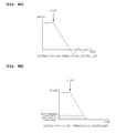
- FIG. 4A is a diagram illustrating the state of a system to which an anti-rebounding controller according to the present invention is not applied
- FIG. 4B is a diagram illustrating the state of a system to which an anti-rebounding controller according to the present invention is applied.
- the present invention can be used in the anti-rebounding control apparatus in the electric swing system of the hybrid excavator, and more particularly, the prevent invention can be used in the anti-rebounding control apparatus in the electric swing system of the hybrid excavator, which can implement the anti-rebounding control system in the electric motor system, and can realize the same performance as that of the anti-rebounding system that is used in the swing system of the existing hydraulic excavator even in the system that performs the swing operation using the electric motor such as the hybrid (or electric) excavator.
Landscapes
- Engineering & Computer Science (AREA)
- Mining & Mineral Resources (AREA)
- Civil Engineering (AREA)
- General Engineering & Computer Science (AREA)
- Structural Engineering (AREA)
- Power Engineering (AREA)
- Automation & Control Theory (AREA)
- Transportation (AREA)
- Mechanical Engineering (AREA)
- Operation Control Of Excavators (AREA)
Abstract
Description
- The present invention relates to an anti-rebounding control apparatus and method in an electric swing system of a hybrid excavator. More particularly, the present invention relates to an anti-rebounding control apparatus and method in an electric swing system of a hybrid excavator, which can implement an anti-rebounding control system in an electric motor system, and can realize the same performance as that of an anti-rebounding system that is used in a swing system of an existing hydraulic excavator even in the system that performs a swing operation using an electric motor such as a hybrid (or electric) excavator.
- An anti-rebounding system that is used in a hydraulic excavator in the related art is a hydraulic circuit system that is configured to stop an upper swing structure of the excavator without bounding in the case of stopping the upper swing structure. This system is also necessary even in a hybrid excavator or an electric excavator system, which performs a swing operation using an electric motor.
- Therefore, the present invention has been made to solve the above-mentioned problems occurring in the related art, and one embodiment of the present invention is related to an anti-rebounding control apparatus and method in an electric swing system of a hybrid excavator, which can implement an anti-rebounding control system even in an electric motor swing control system of a hybrid excavator or an electric excavator, and can realize the same performance as that of an anti-rebounding system that is implemented in the existing hydraulic system through controlling an electric motor inverter for controlling the operation of an electric motor using an anti-rebounding control algorithm implemented in a controller without the necessity of separate hardware as in the existing hydraulic excavator.
- In accordance with one aspect of the present invention, there is provided an anti-rebounding control method in an electric swing system of a hybrid excavator, which includes comparing an electric motor speed feedback value that is a speed value fed back from an electric motor with a preset upper threshold speed value and a preset lower threshold speed value if an input speed command value is "0" (if an operator intends to stop a swing operation of an upper swing structure); setting a torque limit value to "0" if the electric motor speed feedback value is equal to or smaller than the upper threshold speed value and equal to or larger than the lower threshold speed value as the result of comparison, and setting a torque limit value to a maximum value so that a power is re-supplied to the electric motor if the electric motor speed feedback value is smaller than the lower threshold speed value (just before the electric motor stops); and intercepting the power that is supplied to the electric motor if the torque limit value is set to "0" and re-supplying the power to the electric motor if the torque limit value is set to the maximum value.
- Preferably, the step of setting the torque limit value to "0" or the maximum value sets a predetermined rate limit (slope) and changes and sets the torque limit value to "0" or the maximum value in proportion to the set rate limit (slope), and the step of intercepting or supplying the power to the electric motor according to the set torque limit value intercepts or supplies the power in proportion to the set rate limit (slope).
- In accordance with another aspect of the present invention, there is provided an anti-rebounding control apparatus in an electric swing system of a hybrid excavator, which includes an anti-rebounding controller outputting a first command for setting a torque limit value to "0" if an electric motor speed feedback value that is a speed value fed back from an electric motor is equal to or smaller than an upper threshold speed value and equal to or larger than a lower threshold speed value in the case where an input speed command value is "0" (in the case where an operator intends to stop a swing operation of an upper swing structure), and outputting a second command for setting the torque limit value to a maximum value so that a power is re-supplied to the electric motor if the electric motor speed feedback value is smaller than the lower threshold speed value (just before the electric motor stops); a torque regulator setting the torque limit value to "0" when the first command is input and setting the torque limit value to the maximum value so that the power is re-supplied to the electric motor when the second command is input; and an electric motor inverter intercepting the power that is supplied to the electric motor if the torque limit value is set to "0" and re-supplying the power to the electric motor if the torque limit value is set to the maximum value.
- Preferably, the anti-rebounding controller includes a speed value comparison unit comparing the electric motor speed feedback value that is the speed value fed back from the electric motor with the preset upper threshold speed value and the preset lower threshold speed value if the input speed command value is "0" (if the operator intends to stop the swing operation of the upper swing structure); and a command output unit outputting the first command for setting the torque limit value to "0" if the electric motor speed feedback value is equal to or smaller than the upper threshold speed value and equal to or larger than the lower threshold speed value as the result of comparison and outputting the second command for setting the torque limit value to the maximum value so that the power is re-supplied to the electric motor if the electric motor speed feedback value is smaller than the lower threshold speed value (just before the electric motor stops).
- Preferably, the torque regulator changes and sets the torque limit value to "0" or the maximum value in proportion to a set rate limit (slope), and the electric motor inverter intercepts or supplies the power in proportion to the set rate limit (slope).
- According to the present invention, the anti-rebounding system implemented in the existing hydraulic excavator can be implemented even in the electric motor swing control system of the hybrid excavator or the electric excavator.
- Further, the electric motor inverter can be controlled by the anti-rebounding control algorithm implemented in the controller, and through this, the electric motor can be operated in the same manner as that in the anti-rebounding system that is implemented in the existing hydraulic system.
- The above objects, other features and advantages of the present invention will become more apparent by describing the preferred embodiments thereof with reference to the accompanying drawings, in which:
-
Fig. 1 is a block diagram of an anti-rebounding control apparatus in an electric swing system of a hybrid excavator according to the present invention; -
Fig. 2 is a conceptual diagram explaining torque limit setting of a torque regulator according to the present invention; -
Fig. 3 is a flowchart illustrating in order the operation of an anti-rebounding control apparatus in an electric swing system of a hybrid excavator according to the present invention; -
FIG. 4A is a diagram illustrating the state of a system to which an anti-rebounding controller according to the present invention is not applied; and -
FIG. 4B is a diagram illustrating the state of a system to which an anti-rebounding controller according to the present invention is applied. -
- 101: anti-rebounding controller
- 102: torque regulator
- 103: electric motor inverter
- 104: electric motor
- Hereinafter, preferred embodiments of the present invention will be described in detail with reference to the accompanying drawings.
-
Fig. 1 is a block diagram of an anti-rebounding control apparatus in an electric swing system of a hybrid excavator according to the present invention, - As illustrated in
Fig. 1 , an anti-rebounding control apparatus is configured to include ananti-rebounding controller 101 including a speed value comparator and a command output unit, atorque regulator 102, anelectric motor inverter 103, and anelectric motor 104. - Here, the
anti-rebounding controller 101 outputs a first command for setting a torque limit value to "0" if an electric motor speed feedback value that is a speed value fed back from an electric motor is equal to or smaller than an upper threshold speed value and equal to or larger than a lower threshold speed value if an input speed command value is "0" (if an operator intends to stop a swing operation of an upper swing structure), and outputs a second command for setting the torque limit value to a maximum value so that a power is re-supplied to the electric motor if the electric motor speed feedback value is smaller than the lower threshold speed value (just before the electric motor stops). Specifically, theanti-rebounding controller 101 is configured to include a speed value comparison unit (not illustrated) comparing the electric motor speed feedback value that is the speed value fed back from the electric motor with the preset upper threshold speed value and the preset lower threshold speed value if the input speed command value is "0" (if the operator intends to stop the swing operation of the upper swing structure); and a command output unit (not illustrated) outputting the first command for setting the torque limit value to "0" if the electric motor speed feedback value is equal to or smaller than the upper threshold speed value and equal to or larger than the lower threshold speed value as the result of comparison and outputting the second command for setting the torque limit value to the maximum value so that the power is re-supplied to the electric motor if the electric motor speed feedback value is smaller than the lower threshold speed value (just before the electric motor stops). - The
torque regulator 102 sets the torque limit value to "0" when the first command is input from theanti-rebounding controller 101, and sets the torque limit value to the maximum value so as to re-supply the power to theelectric motor 104 when the second command is input. At this time, thetorque regulator 102 sets a predetermined rate limit (slope) for smooth stop of the upper swing structure without impact, and changes and sets the torque limit value to "0" or the maximum value in proportion to the set rate limit (slope). - If the torque limit value is set to "0" by the
torque regulator 102, theelectric motor inverter 103 intercepts the power being supplied to theelectric motor 104, and if the torque limit value is set to the maximum value, theelectric motor inverter 103 re-supplies the power to theelectric motor 104. If the predetermined rate limit (slope) is set to maintain the smooth stop of the upper swing structure without impact, the electric motor inverter 103 intercepts or supplies the power in proportion to the set rate limit (slope). -
Fig. 2 is a conceptual diagram explaining torque limit setting of a torque regulator according to the present invention. As illustrated inFig. 2 , according to the present invention, the torque limit value can be changed for the anti-rebounding. For example, if the electric motor speed feedback value is equal to or smaller than the upper threshold speed value and equal to or larger than the lower threshold speed value, the torque limit value is changed from the maximum value to "0", and if the electric motor speed feedback value is smaller than the lower threshold speed value (just before the electric motor stops), the torque limit value is changed to the maximum value so that the power is re-supplied to the electric motor. - In addition, if the torque limit value is changed, the predetermined rate limit (slope) is set so that the upper swing structure can be smoothly stopped without impact, and the torque limit value is changed and set to "0" or the maximum value in proportion to the set rate limit (slope).
- Next, the operation of the anti-rebounding control apparatus in the electric swing system of the hybrid excavator as illustrated in
Figs. 1 and 2 will be described with reference toFig. 3 . -
Fig. 3 is a flowchart illustrating in order the operation of an anti-rebounding control apparatus in an electric swing system of a hybrid excavator according to the present invention. - As illustrated in
Fig. 3 , according to the present invention, if the input speed command value is "0" (if the operator intends to stop the swing operation of the upper swing structure) (S301), the electric motor speed feedback value is compared with the preset upper threshold speed value and the preset lower threshold speed value (S302). - The speed command value is a speed command value that is desired by an operator with respect to the electric motor system, the motor speed feedback value is a speed value fed back from the electric motor, and the upper threshold speed value and the lower threshold speed value are parameter values set for the anti-rebounding control.
- For reference, if the electric motor speed feedback value is equal to or smaller than the upper threshold speed value and equal to or larger than the lower threshold speed value as the result of comparison, the first command for setting the torque limit value to "0" is output.
- That is, from the moment when the speed command value becomes "0", the speed of the electric motor is decreased, and if the decreased speed is equal to the upper threshold speed value, the torque limit value becomes "0". Accordingly, the electric motor is unable to receive the power for driving from the electric motor inverter.
- Through this, the equipment is naturally stopped without rebounding due to the frictional torque of the equipment itself.
- On the other hand, if the electric motor speed feedback value is smaller than the lower threshold speed value (just before the electric motor stops), the second command for setting the torque limit value to the maximum value is output so as to re-supply the power to the electric motor.
- At the same time, a holding torque may be generated to maintain the present position.
- Next, if the first command is input, the torque limit value is set to "0" (S303), and if the second command is input, the torque limit value is set to the maximum value so that the power can be re-supplied to the electric motor (S304).
- At this time, the predetermined rate limit (slope) is set for the smooth stop of the upper swing structure without impact, and the torque limit value is changed and set to "0" or the maximum value in proportion to the set rate limit (slope).
- Last, if the torque limit value is set to "0", the power that is supplied to the electric motor is intercepted, while if the torque limit value is set to the maximum value, the power is re-supplied to the electric motor.
- At this time, if the predetermined rate limit (slope) is set for the smooth step without impact as described above, the power is intercepted or supplied in proportion to the set rate limit (slope).
- As described above, the torque limit value is set to "0" if the electric motor speed feedback value that is the speed value fed back from the electric motor is equal to or smaller than the upper threshold speed value and equal to or larger than the lower threshold speed value in the case where the input speed command value is "0" (in the case where the operator intends to stop the swing operation of the upper swing structure), and the torque limit value is set to the maximum value so that the power can be re-supplied to the electric motor if the electric motor speed feedback value is smaller than the lower threshold speed value (just before the electric motor stops). Accordingly, the anti-rebounding system implemented in the existing hydraulic excavator can also be implemented even in the electric motor swing control system of the hybrid excavator or the electric excavator.
- Last, referring to
Figs. 4A and 4B , the results of application of the anti-rebounding controller according to the present invention will be described. -
FIG. 4A is a diagram illustrating the state of a system to which an anti-rebounding controller according to the present invention is not applied, andFIG. 4B is a diagram illustrating the state of a system to which an anti-rebounding controller according to the present invention is applied. - As illustrated in
Fig. 4A , in the system to which the anti-rebounding controller is not applied, oscillation is generated at the time when the upper swing structure is stopped, whereas in the system to which the anti-rebounding controller is applied according to the present invention, it can be seen that such oscillation has disappeared. - As apparent from the above description, the present invention can be used in the anti-rebounding control apparatus in the electric swing system of the hybrid excavator, and more particularly, the prevent invention can be used in the anti-rebounding control apparatus in the electric swing system of the hybrid excavator, which can implement the anti-rebounding control system in the electric motor system, and can realize the same performance as that of the anti-rebounding system that is used in the swing system of the existing hydraulic excavator even in the system that performs the swing operation using the electric motor such as the hybrid (or electric) excavator.
Claims (5)
- An anti-rebounding control method in an electric swing system of a hybrid excavator, comprising:comparing an electric motor speed feedback value that is a speed value fed back from an electric motor with a preset upper threshold speed value and a preset lower threshold speed value if an input speed command value is "0" (if an operator intends to stop a swing operation of an upper swing structure);setting a torque limit value to "0" if the electric motor speed feedback value is equal to or smaller than the upper threshold speed value and equal to or larger than the lower threshold speed value as the result of comparison, and setting a torque limit value to a maximum value so that a power is re-supplied to the electric motor if the electric motor speed feedback value is smaller than the lower threshold speed value (just before the electric motor stops); andintercepting the power that is supplied to the electric motor if the torque limit value is set to "0" and re-supplying the power to the electric motor if the torque limit value is set to the maximum value.
- The anti-rebounding control method according to claim 1, wherein the step of setting the torque limit value to "0" or the maximum value sets a predetermined rate limit (slope) and changes and sets the torque limit value to "0" or the maximum value in proportion to the set rate limit (slope), and
the step of intercepting or supplying the power to the electric motor according to the set torque limit value intercepts or supplies the power in proportion to the set rate limit (slope). - An anti-rebounding control apparatus in an electric swing system of a hybrid excavator, comprising:an anti-rebounding controller outputting a first command for setting a torque limit value to "0" if an electric motor speed feedback value that is a speed value fed back from an electric motor is equal to or smaller than an upper threshold speed value and equal to or larger than a lower threshold speed value in the case where an input speed command value is "0" (in the case where an operator intends to stop a swing operation of an upper swing structure), and outputting a second command for setting the torque limit value to a maximum value so that a power is re-supplied to the electric motor if the electric motor speed feedback value is smaller than the lower threshold speed value (just before the electric motor stops);a torque regulator setting the torque limit value to "0" when the first command is input and setting the torque limit value to the maximum value so that the power is re-supplied to the electric motor when the second command is input; andan electric motor inverter intercepting the power that is supplied to the electric motor if the torque limit value is set to "0" and re-supplying the power to the electric motor if the torque limit value is set to the maximum value.
- The anti-rebounding control apparatus according to claim 3, wherein the anti-rebounding controller comprises:a speed value comparison unit comparing the electric motor speed feedback value that is the speed value fed back from the electric motor with the preset upper threshold speed value and the preset lower threshold speed value if the input speed command value is "0" (if the operator intends to stop the swing operation of the upper swing structure); anda command output unit outputting the first command for setting the torque limit value to "0" if the electric motor speed feedback value is equal to or smaller than the upper threshold speed value and equal to or larger than the lower threshold speed value as the result of comparison and outputting the second command for setting the torque limit value to the maximum value so that the power is re-supplied to the electric motor if the electric motor speed feedback value is smaller than the lower threshold speed value (just before the electric motor stops).
- The anti-rebounding control apparatus according to claim 3, wherein the torque regulator changes and sets the torque limit value to "0" or the maximum value in proportion to a set rate limit (slope), and
the electric motor inverter intercepts or supplies the power in proportion to the set rate limit (slope).
Applications Claiming Priority (1)
| Application Number | Priority Date | Filing Date | Title |
|---|---|---|---|
| PCT/KR2011/001985 WO2012128402A1 (en) | 2011-03-23 | 2011-03-23 | Anti-rebounding control apparatus and method in an electrical swing system of a hybrid excavator |
Publications (3)
| Publication Number | Publication Date |
|---|---|
| EP2690224A1 true EP2690224A1 (en) | 2014-01-29 |
| EP2690224A4 EP2690224A4 (en) | 2015-10-28 |
| EP2690224B1 EP2690224B1 (en) | 2021-10-20 |
Family
ID=46879530
Family Applications (1)
| Application Number | Title | Priority Date | Filing Date |
|---|---|---|---|
| EP11861653.1A Active EP2690224B1 (en) | 2011-03-23 | 2011-03-23 | Anti-rebounding control apparatus and method in an electrical swing system of a hybrid excavator |
Country Status (6)
| Country | Link |
|---|---|
| US (1) | US9024565B2 (en) |
| EP (1) | EP2690224B1 (en) |
| JP (1) | JP5815835B2 (en) |
| KR (1) | KR101746533B1 (en) |
| CN (1) | CN103429825B (en) |
| WO (1) | WO2012128402A1 (en) |
Families Citing this family (2)
| Publication number | Priority date | Publication date | Assignee | Title |
|---|---|---|---|---|
| GB2551822B (en) * | 2016-06-30 | 2018-08-22 | Sevcon Ltd | Methods and apparatus for controlling an electric motor |
| WO2025101502A1 (en) * | 2023-11-10 | 2025-05-15 | Doosan Bobcat North America, Inc. | Systems and methods of determining actuator brake capacity |
Family Cites Families (21)
| Publication number | Priority date | Publication date | Assignee | Title |
|---|---|---|---|---|
| DE68925130T2 (en) * | 1988-07-11 | 1996-05-09 | Koyo Seiko Co | Power steering |
| JP2884942B2 (en) * | 1992-09-17 | 1999-04-19 | 株式会社日立製作所 | Electric car control device |
| US6021251A (en) * | 1997-07-08 | 2000-02-01 | Crown Equipment Corporation | Compensated field current control for a separately excited DC motor |
| US6639370B1 (en) | 2000-12-20 | 2003-10-28 | Indigo Energy, Inc. | Speed control for a flywheel energy storage system |
| KR100674516B1 (en) * | 2002-05-09 | 2007-01-26 | 코벨코 겐키 가부시키가이샤 | Rotation control device of working machine |
| JP3910560B2 (en) * | 2003-06-18 | 2007-04-25 | 日立建機株式会社 | Hybrid work vehicle |
| JP4597557B2 (en) * | 2004-03-24 | 2010-12-15 | 住友建機株式会社 | Swivel device for construction machinery |
| CN1950574B (en) * | 2004-05-13 | 2010-09-22 | 株式会社小松制作所 | Rotation control device, rotation control method and construction machine |
| CN100577930C (en) | 2004-05-13 | 2010-01-06 | 株式会社小松制作所 | Swing control device, swing control method and construction machine |
| JPWO2006033401A1 (en) * | 2004-09-24 | 2008-05-15 | 株式会社小松製作所 | Gear drive control device, gear drive control method, turning control device, and construction machine |
| EP1813728A4 (en) * | 2004-11-17 | 2014-09-17 | Komatsu Mfg Co Ltd | Swing control device and construction machinery |
| DE112006002935B4 (en) | 2005-10-28 | 2013-09-05 | Komatsu Ltd. | Control device of a machine, control device of a machine and a hydraulic pump, and control device of a machine, a hydraulic pump and a generator motor |
| JP4740761B2 (en) * | 2006-02-14 | 2011-08-03 | 株式会社小松製作所 | Engine, hydraulic pump and generator motor controller |
| JP2009221664A (en) * | 2008-03-13 | 2009-10-01 | Daikin Ind Ltd | Revolving superstructure control unit |
| CN102046888B (en) * | 2008-05-27 | 2013-02-06 | 住友建机株式会社 | Swing drive controller and construction machine including the same |
| EP2287406B1 (en) * | 2008-05-29 | 2018-05-09 | Sumitomo (S.H.I.) Construction Machinery Co., Ltd. | Swivel drive controller and construction machine including the same |
| JP5611532B2 (en) * | 2009-03-17 | 2014-10-22 | 住友重機械工業株式会社 | Servo control system and work machine |
| KR101112135B1 (en) * | 2009-07-28 | 2012-02-22 | 볼보 컨스트럭션 이큅먼트 에이비 | Swing Control System and Method Of Construction Machine Using Electric Motor |
| JP5767702B2 (en) | 2010-07-21 | 2015-08-19 | ボルボ コンストラクション イクイップメント アーベー | Hybrid excavator emergency stop system |
| JP2014505807A (en) | 2010-12-15 | 2014-03-06 | ボルボ コンストラクション イクイップメント アーベー | Turning control system for hybrid construction machines |
| CN103797194B (en) * | 2011-09-15 | 2016-07-06 | 住友重机械工业株式会社 | Motoring controls the control method of device and rotary motor |
-
2011
- 2011-03-23 US US14/002,039 patent/US9024565B2/en active Active
- 2011-03-23 JP JP2014500975A patent/JP5815835B2/en not_active Expired - Fee Related
- 2011-03-23 CN CN201180069355.0A patent/CN103429825B/en active Active
- 2011-03-23 KR KR1020137022908A patent/KR101746533B1/en active Active
- 2011-03-23 EP EP11861653.1A patent/EP2690224B1/en active Active
- 2011-03-23 WO PCT/KR2011/001985 patent/WO2012128402A1/en not_active Ceased
Also Published As
| Publication number | Publication date |
|---|---|
| JP5815835B2 (en) | 2015-11-17 |
| EP2690224B1 (en) | 2021-10-20 |
| KR20140019338A (en) | 2014-02-14 |
| US9024565B2 (en) | 2015-05-05 |
| JP2014510212A (en) | 2014-04-24 |
| US20130334999A1 (en) | 2013-12-19 |
| EP2690224A4 (en) | 2015-10-28 |
| CN103429825A (en) | 2013-12-04 |
| CN103429825B (en) | 2016-01-06 |
| WO2012128402A1 (en) | 2012-09-27 |
| KR101746533B1 (en) | 2017-06-13 |
Similar Documents
| Publication | Publication Date | Title |
|---|---|---|
| EP3171234B1 (en) | Control device, control method, information processing program, and recording medium | |
| JP5620535B2 (en) | Motor control system that detects voltage saturation | |
| US9008919B2 (en) | Swing control apparatus and method of construction machinery | |
| JP6369590B1 (en) | Motor control system, motor control device, and safety function setting method | |
| US8600527B2 (en) | Acceleration/deceleration control device | |
| US11353830B2 (en) | Servo control method | |
| JP6143984B1 (en) | Inverter device | |
| JP2005073381A (en) | Motor drive control device | |
| US9024565B2 (en) | Anti-rebounding control apparatus and method in an electrical swing system of a hybrid excavator | |
| JP2008168343A (en) | Plasma arc power supply and control method thereof | |
| CN107206527A (en) | The welds types power supply device started for TIG | |
| JP6177623B2 (en) | Synchronous motor controller | |
| JP2015130739A (en) | Motor controller capable of switching presence or absence of flux control application | |
| KR20160139104A (en) | Apparatus for controlling motor | |
| JP2020043631A (en) | Synchronous motor control device | |
| JP5786726B2 (en) | Motor drive control system | |
| JP2018026106A (en) | Motor operation system and method | |
| CN114435869A (en) | A feeder control method, device, equipment and medium | |
| JP2008029189A (en) | Speed control device for electric motor | |
| KR101780590B1 (en) | Apparatus for controlling inverter | |
| KR102112389B1 (en) | Elevator control system, motor control apparatus, and elevator control method | |
| JP7428527B2 (en) | Motor control method, motor drive device, industrial robot control method, and industrial robot | |
| JP4987302B2 (en) | Driving method of stepping motor | |
| JP2006121770A (en) | Vector control device for induction motor and control method therefor | |
| KR20230135806A (en) | Control device and method for a motor |
Legal Events
| Date | Code | Title | Description |
|---|---|---|---|
| PUAI | Public reference made under article 153(3) epc to a published international application that has entered the european phase |
Free format text: ORIGINAL CODE: 0009012 |
|
| 17P | Request for examination filed |
Effective date: 20130826 |
|
| AK | Designated contracting states |
Kind code of ref document: A1 Designated state(s): AL AT BE BG CH CY CZ DE DK EE ES FI FR GB GR HR HU IE IS IT LI LT LU LV MC MK MT NL NO PL PT RO RS SE SI SK SM TR |
|
| RIN1 | Information on inventor provided before grant (corrected) |
Inventor name: KIM, JI-YUN |
|
| RIN1 | Information on inventor provided before grant (corrected) |
Inventor name: KIM, JI-YUN |
|
| DAX | Request for extension of the european patent (deleted) | ||
| RA4 | Supplementary search report drawn up and despatched (corrected) |
Effective date: 20150929 |
|
| RIC1 | Information provided on ipc code assigned before grant |
Ipc: H02P 3/02 20060101ALI20150923BHEP Ipc: B60W 20/00 20060101ALI20150923BHEP Ipc: E02F 9/20 20060101ALI20150923BHEP Ipc: E02F 9/12 20060101AFI20150923BHEP |
|
| GRAP | Despatch of communication of intention to grant a patent |
Free format text: ORIGINAL CODE: EPIDOSNIGR1 |
|
| STAA | Information on the status of an ep patent application or granted ep patent |
Free format text: STATUS: GRANT OF PATENT IS INTENDED |
|
| INTG | Intention to grant announced |
Effective date: 20210630 |
|
| GRAS | Grant fee paid |
Free format text: ORIGINAL CODE: EPIDOSNIGR3 |
|
| GRAA | (expected) grant |
Free format text: ORIGINAL CODE: 0009210 |
|
| STAA | Information on the status of an ep patent application or granted ep patent |
Free format text: STATUS: THE PATENT HAS BEEN GRANTED |
|
| AK | Designated contracting states |
Kind code of ref document: B1 Designated state(s): AL AT BE BG CH CY CZ DE DK EE ES FI FR GB GR HR HU IE IS IT LI LT LU LV MC MK MT NL NO PL PT RO RS SE SI SK SM TR |
|
| REG | Reference to a national code |
Ref country code: GB Ref legal event code: FG4D |
|
| REG | Reference to a national code |
Ref country code: CH Ref legal event code: EP |
|
| REG | Reference to a national code |
Ref country code: IE Ref legal event code: FG4D |
|
| REG | Reference to a national code |
Ref country code: DE Ref legal event code: R096 Ref document number: 602011071979 Country of ref document: DE |
|
| REG | Reference to a national code |
Ref country code: AT Ref legal event code: REF Ref document number: 1440076 Country of ref document: AT Kind code of ref document: T Effective date: 20211115 |
|
| REG | Reference to a national code |
Ref country code: LT Ref legal event code: MG9D |
|
| REG | Reference to a national code |
Ref country code: NL Ref legal event code: MP Effective date: 20211020 |
|
| REG | Reference to a national code |
Ref country code: AT Ref legal event code: MK05 Ref document number: 1440076 Country of ref document: AT Kind code of ref document: T Effective date: 20211020 |
|
| PG25 | Lapsed in a contracting state [announced via postgrant information from national office to epo] |
Ref country code: RS Free format text: LAPSE BECAUSE OF FAILURE TO SUBMIT A TRANSLATION OF THE DESCRIPTION OR TO PAY THE FEE WITHIN THE PRESCRIBED TIME-LIMIT Effective date: 20211020 Ref country code: LT Free format text: LAPSE BECAUSE OF FAILURE TO SUBMIT A TRANSLATION OF THE DESCRIPTION OR TO PAY THE FEE WITHIN THE PRESCRIBED TIME-LIMIT Effective date: 20211020 Ref country code: FI Free format text: LAPSE BECAUSE OF FAILURE TO SUBMIT A TRANSLATION OF THE DESCRIPTION OR TO PAY THE FEE WITHIN THE PRESCRIBED TIME-LIMIT Effective date: 20211020 Ref country code: BG Free format text: LAPSE BECAUSE OF FAILURE TO SUBMIT A TRANSLATION OF THE DESCRIPTION OR TO PAY THE FEE WITHIN THE PRESCRIBED TIME-LIMIT Effective date: 20220120 Ref country code: AT Free format text: LAPSE BECAUSE OF FAILURE TO SUBMIT A TRANSLATION OF THE DESCRIPTION OR TO PAY THE FEE WITHIN THE PRESCRIBED TIME-LIMIT Effective date: 20211020 |
|
| PG25 | Lapsed in a contracting state [announced via postgrant information from national office to epo] |
Ref country code: IS Free format text: LAPSE BECAUSE OF FAILURE TO SUBMIT A TRANSLATION OF THE DESCRIPTION OR TO PAY THE FEE WITHIN THE PRESCRIBED TIME-LIMIT Effective date: 20220220 Ref country code: SE Free format text: LAPSE BECAUSE OF FAILURE TO SUBMIT A TRANSLATION OF THE DESCRIPTION OR TO PAY THE FEE WITHIN THE PRESCRIBED TIME-LIMIT Effective date: 20211020 Ref country code: PT Free format text: LAPSE BECAUSE OF FAILURE TO SUBMIT A TRANSLATION OF THE DESCRIPTION OR TO PAY THE FEE WITHIN THE PRESCRIBED TIME-LIMIT Effective date: 20220221 Ref country code: PL Free format text: LAPSE BECAUSE OF FAILURE TO SUBMIT A TRANSLATION OF THE DESCRIPTION OR TO PAY THE FEE WITHIN THE PRESCRIBED TIME-LIMIT Effective date: 20211020 Ref country code: NO Free format text: LAPSE BECAUSE OF FAILURE TO SUBMIT A TRANSLATION OF THE DESCRIPTION OR TO PAY THE FEE WITHIN THE PRESCRIBED TIME-LIMIT Effective date: 20220120 Ref country code: NL Free format text: LAPSE BECAUSE OF FAILURE TO SUBMIT A TRANSLATION OF THE DESCRIPTION OR TO PAY THE FEE WITHIN THE PRESCRIBED TIME-LIMIT Effective date: 20211020 Ref country code: LV Free format text: LAPSE BECAUSE OF FAILURE TO SUBMIT A TRANSLATION OF THE DESCRIPTION OR TO PAY THE FEE WITHIN THE PRESCRIBED TIME-LIMIT Effective date: 20211020 Ref country code: HR Free format text: LAPSE BECAUSE OF FAILURE TO SUBMIT A TRANSLATION OF THE DESCRIPTION OR TO PAY THE FEE WITHIN THE PRESCRIBED TIME-LIMIT Effective date: 20211020 Ref country code: GR Free format text: LAPSE BECAUSE OF FAILURE TO SUBMIT A TRANSLATION OF THE DESCRIPTION OR TO PAY THE FEE WITHIN THE PRESCRIBED TIME-LIMIT Effective date: 20220121 Ref country code: ES Free format text: LAPSE BECAUSE OF FAILURE TO SUBMIT A TRANSLATION OF THE DESCRIPTION OR TO PAY THE FEE WITHIN THE PRESCRIBED TIME-LIMIT Effective date: 20211020 |
|
| REG | Reference to a national code |
Ref country code: DE Ref legal event code: R097 Ref document number: 602011071979 Country of ref document: DE |
|
| PG25 | Lapsed in a contracting state [announced via postgrant information from national office to epo] |
Ref country code: SM Free format text: LAPSE BECAUSE OF FAILURE TO SUBMIT A TRANSLATION OF THE DESCRIPTION OR TO PAY THE FEE WITHIN THE PRESCRIBED TIME-LIMIT Effective date: 20211020 Ref country code: SK Free format text: LAPSE BECAUSE OF FAILURE TO SUBMIT A TRANSLATION OF THE DESCRIPTION OR TO PAY THE FEE WITHIN THE PRESCRIBED TIME-LIMIT Effective date: 20211020 Ref country code: RO Free format text: LAPSE BECAUSE OF FAILURE TO SUBMIT A TRANSLATION OF THE DESCRIPTION OR TO PAY THE FEE WITHIN THE PRESCRIBED TIME-LIMIT Effective date: 20211020 Ref country code: EE Free format text: LAPSE BECAUSE OF FAILURE TO SUBMIT A TRANSLATION OF THE DESCRIPTION OR TO PAY THE FEE WITHIN THE PRESCRIBED TIME-LIMIT Effective date: 20211020 Ref country code: DK Free format text: LAPSE BECAUSE OF FAILURE TO SUBMIT A TRANSLATION OF THE DESCRIPTION OR TO PAY THE FEE WITHIN THE PRESCRIBED TIME-LIMIT Effective date: 20211020 Ref country code: CZ Free format text: LAPSE BECAUSE OF FAILURE TO SUBMIT A TRANSLATION OF THE DESCRIPTION OR TO PAY THE FEE WITHIN THE PRESCRIBED TIME-LIMIT Effective date: 20211020 |
|
| PLBE | No opposition filed within time limit |
Free format text: ORIGINAL CODE: 0009261 |
|
| STAA | Information on the status of an ep patent application or granted ep patent |
Free format text: STATUS: NO OPPOSITION FILED WITHIN TIME LIMIT |
|
| 26N | No opposition filed |
Effective date: 20220721 |
|
| PG25 | Lapsed in a contracting state [announced via postgrant information from national office to epo] |
Ref country code: MC Free format text: LAPSE BECAUSE OF FAILURE TO SUBMIT A TRANSLATION OF THE DESCRIPTION OR TO PAY THE FEE WITHIN THE PRESCRIBED TIME-LIMIT Effective date: 20211020 Ref country code: AL Free format text: LAPSE BECAUSE OF FAILURE TO SUBMIT A TRANSLATION OF THE DESCRIPTION OR TO PAY THE FEE WITHIN THE PRESCRIBED TIME-LIMIT Effective date: 20211020 |
|
| REG | Reference to a national code |
Ref country code: CH Ref legal event code: PL |
|
| GBPC | Gb: european patent ceased through non-payment of renewal fee |
Effective date: 20220323 |
|
| PG25 | Lapsed in a contracting state [announced via postgrant information from national office to epo] |
Ref country code: SI Free format text: LAPSE BECAUSE OF FAILURE TO SUBMIT A TRANSLATION OF THE DESCRIPTION OR TO PAY THE FEE WITHIN THE PRESCRIBED TIME-LIMIT Effective date: 20211020 |
|
| REG | Reference to a national code |
Ref country code: BE Ref legal event code: MM Effective date: 20220331 |
|
| PG25 | Lapsed in a contracting state [announced via postgrant information from national office to epo] |
Ref country code: LU Free format text: LAPSE BECAUSE OF NON-PAYMENT OF DUE FEES Effective date: 20220323 Ref country code: LI Free format text: LAPSE BECAUSE OF NON-PAYMENT OF DUE FEES Effective date: 20220331 Ref country code: IE Free format text: LAPSE BECAUSE OF NON-PAYMENT OF DUE FEES Effective date: 20220323 Ref country code: GB Free format text: LAPSE BECAUSE OF NON-PAYMENT OF DUE FEES Effective date: 20220323 Ref country code: CH Free format text: LAPSE BECAUSE OF NON-PAYMENT OF DUE FEES Effective date: 20220331 |
|
| PG25 | Lapsed in a contracting state [announced via postgrant information from national office to epo] |
Ref country code: BE Free format text: LAPSE BECAUSE OF NON-PAYMENT OF DUE FEES Effective date: 20220331 |
|
| PG25 | Lapsed in a contracting state [announced via postgrant information from national office to epo] |
Ref country code: IT Free format text: LAPSE BECAUSE OF FAILURE TO SUBMIT A TRANSLATION OF THE DESCRIPTION OR TO PAY THE FEE WITHIN THE PRESCRIBED TIME-LIMIT Effective date: 20211020 |
|
| PG25 | Lapsed in a contracting state [announced via postgrant information from national office to epo] |
Ref country code: HU Free format text: LAPSE BECAUSE OF FAILURE TO SUBMIT A TRANSLATION OF THE DESCRIPTION OR TO PAY THE FEE WITHIN THE PRESCRIBED TIME-LIMIT; INVALID AB INITIO Effective date: 20110323 |
|
| PG25 | Lapsed in a contracting state [announced via postgrant information from national office to epo] |
Ref country code: MK Free format text: LAPSE BECAUSE OF FAILURE TO SUBMIT A TRANSLATION OF THE DESCRIPTION OR TO PAY THE FEE WITHIN THE PRESCRIBED TIME-LIMIT Effective date: 20211020 Ref country code: CY Free format text: LAPSE BECAUSE OF FAILURE TO SUBMIT A TRANSLATION OF THE DESCRIPTION OR TO PAY THE FEE WITHIN THE PRESCRIBED TIME-LIMIT Effective date: 20211020 |
|
| PGFP | Annual fee paid to national office [announced via postgrant information from national office to epo] |
Ref country code: FR Payment date: 20240327 Year of fee payment: 14 |
|
| PG25 | Lapsed in a contracting state [announced via postgrant information from national office to epo] |
Ref country code: MT Free format text: LAPSE BECAUSE OF FAILURE TO SUBMIT A TRANSLATION OF THE DESCRIPTION OR TO PAY THE FEE WITHIN THE PRESCRIBED TIME-LIMIT Effective date: 20211020 |
|
| PG25 | Lapsed in a contracting state [announced via postgrant information from national office to epo] |
Ref country code: TR Free format text: LAPSE BECAUSE OF FAILURE TO SUBMIT A TRANSLATION OF THE DESCRIPTION OR TO PAY THE FEE WITHIN THE PRESCRIBED TIME-LIMIT Effective date: 20211020 |
|
| PG25 | Lapsed in a contracting state [announced via postgrant information from national office to epo] |
Ref country code: FR Free format text: LAPSE BECAUSE OF NON-PAYMENT OF DUE FEES Effective date: 20250331 |
|
| PGFP | Annual fee paid to national office [announced via postgrant information from national office to epo] |
Ref country code: DE Payment date: 20260320 Year of fee payment: 16 |