EP2689970A1 - Switching assembly for controlling an inductive consumer with free-wheeling circuit - Google Patents
Switching assembly for controlling an inductive consumer with free-wheeling circuit Download PDFInfo
- Publication number
- EP2689970A1 EP2689970A1 EP13173677.9A EP13173677A EP2689970A1 EP 2689970 A1 EP2689970 A1 EP 2689970A1 EP 13173677 A EP13173677 A EP 13173677A EP 2689970 A1 EP2689970 A1 EP 2689970A1
- Authority
- EP
- European Patent Office
- Prior art keywords
- switch
- load
- circuit arrangement
- diode
- capacitor
- Prior art date
- Legal status (The legal status is an assumption and is not a legal conclusion. Google has not performed a legal analysis and makes no representation as to the accuracy of the status listed.)
- Withdrawn
Links
- 230000001939 inductive effect Effects 0.000 title claims description 21
- 239000003990 capacitor Substances 0.000 claims abstract description 12
- 230000005540 biological transmission Effects 0.000 claims description 3
- 239000004065 semiconductor Substances 0.000 description 4
- 230000007547 defect Effects 0.000 description 3
- 230000003071 parasitic effect Effects 0.000 description 3
- 230000003213 activating effect Effects 0.000 description 2
- 238000007600 charging Methods 0.000 description 2
- 230000005347 demagnetization Effects 0.000 description 2
- 238000000034 method Methods 0.000 description 2
- 239000007858 starting material Substances 0.000 description 2
- XUIMIQQOPSSXEZ-UHFFFAOYSA-N Silicon Chemical compound [Si] XUIMIQQOPSSXEZ-UHFFFAOYSA-N 0.000 description 1
- 230000004913 activation Effects 0.000 description 1
- 230000000903 blocking effect Effects 0.000 description 1
- 230000001419 dependent effect Effects 0.000 description 1
- 238000010586 diagram Methods 0.000 description 1
- 238000007599 discharging Methods 0.000 description 1
- 238000004870 electrical engineering Methods 0.000 description 1
- 238000005516 engineering process Methods 0.000 description 1
- 239000000446 fuel Substances 0.000 description 1
- 238000002347 injection Methods 0.000 description 1
- 239000007924 injection Substances 0.000 description 1
- 229910052710 silicon Inorganic materials 0.000 description 1
- 239000010703 silicon Substances 0.000 description 1
- 238000004513 sizing Methods 0.000 description 1
Images

Classifications
-
- H—ELECTRICITY
- H02—GENERATION; CONVERSION OR DISTRIBUTION OF ELECTRIC POWER
- H02H—EMERGENCY PROTECTIVE CIRCUIT ARRANGEMENTS
- H02H9/00—Emergency protective circuit arrangements for limiting excess current or voltage without disconnection
- H02H9/04—Emergency protective circuit arrangements for limiting excess current or voltage without disconnection responsive to excess voltage
- H02H9/045—Emergency protective circuit arrangements for limiting excess current or voltage without disconnection responsive to excess voltage adapted to a particular application and not provided for elsewhere
- H02H9/047—Free-wheeling circuits
-
- H—ELECTRICITY
- H01—ELECTRIC ELEMENTS
- H01F—MAGNETS; INDUCTANCES; TRANSFORMERS; SELECTION OF MATERIALS FOR THEIR MAGNETIC PROPERTIES
- H01F7/00—Magnets
- H01F7/06—Electromagnets; Actuators including electromagnets
- H01F7/08—Electromagnets; Actuators including electromagnets with armatures
- H01F7/18—Circuit arrangements for obtaining desired operating characteristics, e.g. for slow operation, for sequential energisation of windings, for high-speed energisation of windings
- H01F7/1805—Circuit arrangements for holding the operation of electromagnets or for holding the armature in attracted position with reduced energising current
- H01F7/1811—Circuit arrangements for holding the operation of electromagnets or for holding the armature in attracted position with reduced energising current demagnetising upon switching off, removing residual magnetism
Definitions
- the invention relates to a circuit arrangement, in particular for the operation of one or more inductive consumers.
- the DE 10 2011 011 295 A1 discloses a circuit for operating one or more inductive loads, in which the control of a second controllable switching element via an operating voltage, wherein a Zener diode is connected in series between the operating voltage and a control input of the second switching element.
- the local term "LOAD" is to be understood as an electrical load or electrical load. This may be, for example, the exciter coil of a starter motor, a solenoid valve for activating a differential lock or an automatic transmission.
- the symbols in the drawings are common symbols of electrical engineering.
- freewheeling diodes are often used to reduce the energy stored in the inductance after switching off and thus to achieve a so-called demagnetization.
- a freewheeling diode serves to protect a mechanical or electronic switch from an overvoltage that is generated when switching off a switched from him inductive DC load.
- a semiconductor diode is connected in parallel with the inductive DC load to be switched so that it is stressed by a supply voltage in the reverse direction. After the supply voltage has been switched off, the self-induction, for example of the coil, ensures that the current initially continues to flow in the original direction. Without the arrangement of the freewheeling diode switching off the supply voltage leads to a voltage spike, which adds to the operating voltage and can damage or destroy the switching path.
- the voltage spike is limited to the forward voltage of the semiconductor diode, which is about 0.7 V in a silicon diode, thereby providing effective overvoltage protection.
- the current flows through the semiconductor diode and the energy of the magnetic field is largely in the ohmic resistance of the coil and converted to a small part in the semiconductor diode into heat.
- Free-wheeling diodes are particularly important when the inductive load is operated in a pulse-width-modulated manner (PWM operation).
- PWM operation a freewheeling average current proportional to the duty cycle of on / off time can be set in the load.
- Typical inductive loads are for example solenoid valves, which are used in motor vehicles, especially in commercial vehicles.
- the inductive load is bipolar connected to the control unit (ECU), such as the motor vehicle, in addition to the electromagnetic advantages in PWM operation, in the case of a break in the power supply in the ground branch no parasitic current can flow to the load.
- ECU control unit
- the invention has the object to improve a circuit arrangement such that An unwanted activation, in particular an inductive load is reliably avoided even with technical defects.
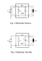
- Fig. 1 is the regular current flow I L shown with two-pole load connection. If the load is connected to a control unit with two poles, the reverse current I L flows back through the control unit. The dashed line illustrates the current flow.
- FIG. 2 To Fig. 2 is the current flow I L in the freewheel with a two-pole load connection represented by the dashed line.
- the energy stored in the inductive load is dissipated via a freewheeling path, demagnetized.
- the current loop that forms is correspondingly small.
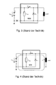
- Fig. 3 is a Masseabriss in two-pole load connection through the large cross shown lower left. This means that, for example, due to a technical defect, a ground cable no longer forms any contact between the circuit arrangement and the negative pole of the battery in the motor vehicle. In the case of a two-pole load connection, the current flow is interrupted in the event of a ground fault.
- Fig. 4 is the regular current flow I L at one-pole load connection represented by the dashed line. If the load is connected to the control unit with a single pole, the reverse current flows via the system ground to the negative terminal of the battery.
- Fig. 5 To Fig. 5 is the current flow I L freewheeling in unipolar load connection represented by the dashed line.
- the switch S 1 When opening the switch S 1 , the energy stored in the inductive load via the freewheeling path is reduced (demagnetized). In the case of a single-pole load connection, the current loop that forms is correspondingly large.
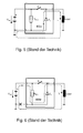
- Fig. 6 is the current flow I L during mass split at one-pole load connection represented by the dashed line.
- this certain parasitic current flows via the control unit (ECU) and the freewheeling diode D 1 to the load and system ground.
- the forming current is dependent on the internal resistance R ECU of the control unit and can activate the connected load unintentionally.
- the Fig. 7 shows a circuit arrangement according to the invention with dynamic freewheeling.
- a load connected to the control unit can be activated unintentionally via its freewheel device, such as a single diode.
- the circuit arrangement shown here prevents this.
- a forward-biased diode is connected in series with a capacitor C 1 , which has a resistance R 1 connected in parallel.
- a further switch S 2 is provided in addition to the switch S 1 , which is bridged with a diode which is likewise connected in the forward direction.
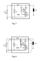
- Fig. 8 is the regular current flow I L at one-pole load connection with dynamic freewheel represented by the dashed line.
- the capacitor C 1 When activating the load, the capacitor C 1 is simultaneously charged by a further current flow I C , as the dotted line illustrates.
- FIG. 9 the current flow I L in the dynamic freewheel with a one-pole load connection is shown by the dashed line.
- the freewheel is only activated until the capacitor C 1 is discharged through the resistor R 1 , as the dotted line shows.
- the dimensioning of C 1 and R 1 is chosen so that the corresponding time constant, which is formed from C 1 * R 1 , is greater than the time constant representing the inductive load with L L / R L.
- Fig. 10 the operating situation during mass break is shown with a one-pole load connection with dynamic freewheel. After the capacitor C 1 is discharged, the switch S 2 opens and the current flow is interrupted. In the case of a Masseabrisses no unwanted current can flow to the load.
- FIG. 11 is a possible circuit design shown with dynamic freewheel.
- a switch S 2 a conventional N-channel MOS-Fet transistor can be used.
- a zener diode ZD 1 is used to limit the gate voltage, which typically may not exceed 20V.
- the freewheeling diode D 1 and the switch S 2 must be selected so that they can carry the impressed current into the connected load during the freewheeling (Demagnetleitersphase).
- the time constant t charge for charging the capacitor C 1 must be less than the minimum duty cycle of the switch S 1 . This is also called a "minimum duty cycle”.
- the time constant t discharge must be greater than the time constant given by the inductive load, ie: (R 1 + R 2 ) * C 1 > L L / R L.
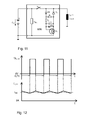
- the so-called PWM operation the inductive load, flows in it a triangular current I load whose mean value l avg is proportional to the pulse width.
- I load whose mean value l avg is proportional to the pulse width.
- the freewheeling branch is to be designed in such a way that, on the one hand, the inductive load connected in a single pole can be operated with PWM, and on the other hand, if there is a possible disconnection of the ground line of the control unit, no unwanted current flows to the load.
- Such a circuit arrangement is preferably used in a motor vehicle for controlling inductive loads, in particular for controlling solenoid valves of a differential lock or an automatic transmission.
Abstract
Description
Die Erfindung bezieht sich auf eine Schaltungsanordnung, insbesondere zum Betrieb eines oder mehrerer induktiver Verbraucher.The invention relates to a circuit arrangement, in particular for the operation of one or more inductive consumers.
Aus der
Die
Im Folgenden wird unter Bezugnahme auf die Figuren darauf verwiesen, dass der dortige Begriff "LOAD" als elektrischer Verbraucher bzw. elektrische Last zu verstehen ist. Dabei kann es sich beispielsweise um die Erregerspule eines Anlassermotors, ein Magnetventil zum Aktivieren einer Differenzialsperre oder eines automatischen Getriebes handeln. Die Symbole in den Zeichnungen sind übliche Symbole aus der Elektrotechnik.In the following reference is made to the figures that the local term "LOAD" is to be understood as an electrical load or electrical load. This may be, for example, the exciter coil of a starter motor, a solenoid valve for activating a differential lock or an automatic transmission. The symbols in the drawings are common symbols of electrical engineering.
In Geräten oder Systemen zum Betrieb von induktiven Lasten werden häufig Freilaufdioden verwendet, um die nach Abschalten in der Induktivität gespeicherte Energie abzubauen und damit eine sogenannte Demagnetisierung zu erzielen.In devices or systems for operating inductive loads freewheeling diodes are often used to reduce the energy stored in the inductance after switching off and thus to achieve a so-called demagnetization.
Eine Freilaufdiode dient zum Schutz eines mechanischen oder elektronischen Schalters vor einer Überspannung, die beim Abschalten einer von ihm geschalteten induktiven Gleichstromlast erzeugt wird. Eine Halbleiterdiode wird derart parallel zu der zu schaltenden induktiven Gleichstromlast geschaltet, dass sie von einer Speisespannung in Sperrrichtung beansprucht wird. Nach dem Abschalten der Speisespannung sorgt die Selbstinduktion, beispielsweise der Spule, dafür, dass der Strom zunächst in der ursprünglichen Richtung weiter fließt. Ohne die Anordnung der Freilaufdiode führt das Abschalten der Speisespannung zu einer Spannungsspitze, die sich zur Betriebsspannung addiert und die Schaltstrecke beschädigen oder zerstören kann. Mit einer Freilaufdiode wird die Spannungsspitze jedoch auf die Durchlassspannung der Halbleiterdiode, die bei einer Silizium-Diode etwa 0,7 V beträgt, begrenzt, wodurch ein effektiver Überspannungsschutz gegeben ist. Der Strom fließt über die Halbleiterdiode und die Energie des Magnetfeldes wird größtenteils im ohmschen Widerstand der Spule und zu einem geringen Teil in der Halbleiterdiode in Wärme umgewandelt.A freewheeling diode serves to protect a mechanical or electronic switch from an overvoltage that is generated when switching off a switched from him inductive DC load. A semiconductor diode is connected in parallel with the inductive DC load to be switched so that it is stressed by a supply voltage in the reverse direction. After the supply voltage has been switched off, the self-induction, for example of the coil, ensures that the current initially continues to flow in the original direction. Without the arrangement of the freewheeling diode switching off the supply voltage leads to a voltage spike, which adds to the operating voltage and can damage or destroy the switching path. However, with a freewheeling diode, the voltage spike is limited to the forward voltage of the semiconductor diode, which is about 0.7 V in a silicon diode, thereby providing effective overvoltage protection. The current flows through the semiconductor diode and the energy of the magnetic field is largely in the ohmic resistance of the coil and converted to a small part in the semiconductor diode into heat.
Freilaufdioden sind insbesondere dann wichtig, wenn die induktive Last pulsweiten-moduliert betrieben wird (PWM-Betrieb). Bei einem PWM-Betrieb kann wegen des Freilaufs ein zum Tastverhältnis von Ein-/Ausschaltzeit proportionaler mittlerer Strom in der Last eingestellt werden.Free-wheeling diodes are particularly important when the inductive load is operated in a pulse-width-modulated manner (PWM operation). In PWM operation, a freewheeling average current proportional to the duty cycle of on / off time can be set in the load.
Typische induktive Lasten sind beispielsweise Magnetventile, welche in Kraftfahrzeugen, insbesondere in Nutzfahrzeugen Verwendung finden.Typical inductive loads are for example solenoid valves, which are used in motor vehicles, especially in commercial vehicles.
Wenn die induktive Last zweipolig mit dem Steuergerät (ECU), beispielsweise des Kraftfahrzeugs, verbunden ist, kann, neben den elektromagnetischen Vorteilen im PWM-Betrieb, im Falle eines Abrisses der Stromzufuhr im Massezweig kein parasitärer Strom zur Last abfließen.If the inductive load is bipolar connected to the control unit (ECU), such as the motor vehicle, in addition to the electromagnetic advantages in PWM operation, in the case of a break in the power supply in the ground branch no parasitic current can flow to the load.
In der Kraftfahrzeugtechnik kommt es häufig vor, dass aus verkabelungstechnischen Gründen die Last nur einpolig mit dem jeweiligen Steuergerät verbunden ist, während der zweite Anschluss der Last mit der System-Masse an einem beliebigen Punkt des Kraftfahrzeuges verbunden ist. Diese Anschlussart hat unter anderem den Nachteil, dass im Falle eines Masseabrisses am Steuergerät ein parasitärer Strom zur Last abfließen und diese unkontrolliert aktivieren kann.In automotive technology, it often happens that the cabling-technical reasons, the load is connected only one pole with the respective control unit, while the second terminal of the load is connected to the system ground at any point of the motor vehicle. One of the disadvantages of this type of connection is that in the event of a ground fault on the control unit, a parasitic current flows to the load and can activate it in an uncontrolled manner.
Ausgehend von diesem Stand der Technik liegt der Erfindung die Aufgabe zugrunde, eine Schaltungsanordnung derart zu verbessern, dass eine ungewollte Aktivierung insbesondere einer induktiven Last auch bei technischen Defekten zuverlässig vermieden ist.Based on this prior art, the invention has the object to improve a circuit arrangement such that An unwanted activation, in particular an inductive load is reliably avoided even with technical defects.
Diese Aufgabe wird durch eine Schaltungsanordnung mit den Merkmalen des Anspruchs 1 gelöst. Weiterhin ist eine vorteilhafte Verwendung der Schaltungsanordnung angegeben.This object is achieved by a circuit arrangement with the features of
Die Unteransprüche stellen vorteilhafte Ausgestaltungen der Erfindung dar.The subclaims represent advantageous embodiments of the invention.
Die Erfindung wird im Folgenden anhand von Ausführungsbeispielen unter Bezugnahme auf die Zeichnung näher erläutert. Die
- Fig. 1
- regulärer Stromfluss bei einem zweipoligen Lastanschluss nach dem Stand der Technik,
- Fig. 2
- Stromfluss im Freilauf bei einem zweipoligen Lastanschluss nach dem Stand der Technik,
- Fig. 3
- Masseabriss bei einem zweipoligen Lastanschluss nach dem Stand der Technik,
- Fig. 4
- regulärer Stromfluss bei einpoligem Lastanschluss nach dem Stand der Technik,
- Fig. 5
- Stromfluss im Freilauf bei einem einpoligen Lastanschluss nach dem Stand der Technik,
- Fig. 6
- Stromfluss während Masseabriss bei einem einpoligen Lastanschluss nach dem Stand der Technik,
- Fig. 7
- Schaltungsanordnung mit einem dynamischen Freilauf nach der Erfindung,
- Fig. 8
- regulärer Stromfluss bei einem einpoligen Lastanschluss und dynamisch aktiviertem Freilauf,
- Fig. 9
- Stromfluss während dynamisch aktiviertem Freilaufs bei einpoligem Lastanschluss,
- Fig. 10
- Stromfluss während Masseabriss bei einpoligem Lastanschluss und dynamisch deaktiviertem Freilauf
- Fig. 11
- ein Applikationsbeispiel mit einer dynamischen Freilaufschaltung und
- Fig. 12
- Diagramme zur Darstellung des Zusammenhangs zwischen dem Spannungs- und Stromverlauf über der Zeit.
- Fig. 1
- regular current flow in a two-pole load terminal according to the prior art,
- Fig. 2
- Free-flowing current flow in a two-pole load connection according to the prior art,
- Fig. 3
- Mass split in a two-pole load connection according to the prior art,
- Fig. 4
- regular current flow in the case of a single-pole load connection according to the prior art,
- Fig. 5
- Current flow in the freewheel in a single-pole load connection according to the prior art,
- Fig. 6
- Current flow during ground rupture in a single-pole load terminal according to the prior art,
- Fig. 7
- Circuit arrangement with a dynamic freewheel according to the invention,
- Fig. 8
- regular current flow with a single-pole load connection and dynamically activated freewheel,
- Fig. 9
- Current flow during dynamically activated freewheel with single-pole load connection,
- Fig. 10
- Current flow during earth rupture with single-pole load connection and dynamically deactivated freewheel
- Fig. 11
- an application example with a dynamic freewheeling circuit and
- Fig. 12
- Diagrams showing the relationship between voltage and current over time.
In
Nach
In
In
Nach
Gemäß
Die
Dabei ist zusätzlich eine in Durchlassrichtung betriebene Diode in Reihe zu einem Kondensator C1 geschaltet, der einen parallel geschalteten Widerstand R1 aufweist. In Reihe zu der in Sperrrichtung geschalteten Freilaufdiode D1 ist neben dem Schalter S1 ein weiterer Schalter S2 vorgesehen, der mit einer ebenfalls in Durchlassrichtung geschalteten Diode überbrückt ist.In addition, a forward-biased diode is connected in series with a capacitor C 1 , which has a resistance R 1 connected in parallel. In series with the freewheeling diode D 1 connected in the blocking direction, a further switch S 2 is provided in addition to the switch S 1 , which is bridged with a diode which is likewise connected in the forward direction.
In
Nach
Gemäß
In
Dabei gelten folgende Dimensionierungsregeln:The following sizing rules apply:
Die Freilaufdiode D1 und der Schalter S2 müssen so gewählt werden, dass sie den eingeprägten Strom in die angeschlossene Last während des Freilaufs (Demagnetisierungsphase) tragen können. Die Zeitkonstante tcharge zum Laden des Kondensators C1 muss kleiner sein als die minimale Einschaltdauer des Schalters S1. Dies wird auch als "minimum duty cycle" bezeichnet. Die Zeitkonstante tdischarge muss größer sein als die Zeitkonstante, die durch die induktive Last vorgegeben wird, also: (R1+R2)*C1 > LL/RL.The freewheeling diode D 1 and the switch S 2 must be selected so that they can carry the impressed current into the connected load during the freewheeling (Demagnetisierungsphase). The time constant t charge for charging the capacitor C 1 must be less than the minimum duty cycle of the switch S 1 . This is also called a "minimum duty cycle". The time constant t discharge must be greater than the time constant given by the inductive load, ie: (R 1 + R 2 ) * C 1 > L L / R L.
Bei der puls-weiten-modulierten Ansteuerung, dem so genannten PWM-Betrieb, der induktiven Last, fließt in ihr ein dreieckförmiger Strom ILoad dessen Mittelwert lavg proportional der Pulsbreite ist. Dies wird dadurch bewirkt, dass nach dem Öffnen des Schalters S1 der Laststrom durch den Freilaufzweig, der durch die in Reihe mit dem Schalter S2 angeordnete Freilaufdiode D1 solange weiterfließt, bis entweder die Induktivität demagnetisiert ist, oder der Schalter S1 wieder eingeschaltet wird. Während der Demagnetisierung der Induktivität bewirkt die Durchlassspannung der Freilaufdiode D1 an der Last eine Spannung von typischen ULoad = -0,7V.In the pulse-width-modulated control, the so-called PWM operation, the inductive load, flows in it a triangular current I load whose mean value l avg is proportional to the pulse width. This is effected by the fact that after the opening of the switch S1, the load current through the freewheeling branch, which continues to flow through the freewheeling diode D1 arranged in series with the switch S2, until either the inductance is demagnetized, or the switch S1 is turned on again. During the demagnetization of the inductance causes the forward voltage of the freewheeling diode D1 at the load a voltage of typical U Load = -0.7V.
Der Freilaufzweig ist derart auszuführen, dass zum einen die einpolig angeschlossene induktive Last mit PWM betrieben werden kann, und zum anderen nach einem eventuellen Abriss der Masseleitung des Steuergerätes kein ungewollter Strom zur Last abfließt.The freewheeling branch is to be designed in such a way that, on the one hand, the inductive load connected in a single pole can be operated with PWM, and on the other hand, if there is a possible disconnection of the ground line of the control unit, no unwanted current flows to the load.
Bevorzugt wird eine solche Schaltungsanordnung in einem Kraftfahrzeug zur Steuerung induktiver Verbraucher, insbesondere zur Steuerung von Magnetventilen einer Differenzialsperre oder eines automatischen Getriebes, verwendet.Such a circuit arrangement is preferably used in a motor vehicle for controlling inductive loads, in particular for controlling solenoid valves of a differential lock or an automatic transmission.
Claims (5)
Applications Claiming Priority (2)
| Application Number | Priority Date | Filing Date | Title |
|---|---|---|---|
| DE102012013362 | 2012-07-08 | ||
| DE102012109011.4A DE102012109011A1 (en) | 2012-07-08 | 2012-09-25 | circuitry |
Publications (1)
| Publication Number | Publication Date |
|---|---|
| EP2689970A1 true EP2689970A1 (en) | 2014-01-29 |
Family
ID=48746283
Family Applications (1)
| Application Number | Title | Priority Date | Filing Date |
|---|---|---|---|
| EP13173677.9A Withdrawn EP2689970A1 (en) | 2012-07-08 | 2013-06-25 | Switching assembly for controlling an inductive consumer with free-wheeling circuit |
Country Status (2)
| Country | Link |
|---|---|
| EP (1) | EP2689970A1 (en) |
| DE (1) | DE102012109011A1 (en) |
Families Citing this family (2)
| Publication number | Priority date | Publication date | Assignee | Title |
|---|---|---|---|---|
| US8917135B2 (en) * | 2013-05-14 | 2014-12-23 | Infineon Technologies Austria Ag | Circuit with a plurality of diodes and method for controlling such a circuit |
| DE102018203887B4 (en) * | 2018-03-14 | 2022-05-25 | Bayerische Motoren Werke Aktiengesellschaft | Control device for a multi-voltage vehicle electrical system and multi-voltage vehicle electrical system |
Citations (3)
| Publication number | Priority date | Publication date | Assignee | Title |
|---|---|---|---|---|
| DE19806311A1 (en) * | 1998-02-16 | 1999-08-26 | Siemens Ag | Device for switching inductive load, such as solenoid valve in motor vehicle |
| WO2005055387A1 (en) * | 2003-12-01 | 2005-06-16 | Siemens Aktiengesellschaft | Circuit system and method for controlling an inductive consumer |
| DE102011011295A1 (en) | 2011-02-15 | 2012-08-16 | Hella Kgaa Hueck & Co. | Power supply arrangement for Ohm's-inductive load in direct current (DC) voltage circuit, has capacitor, Zener diode, and ohmic resistor over which potential at terminal is dropped when transistor is switched OFF in normal operation |
-
2012
- 2012-09-25 DE DE102012109011.4A patent/DE102012109011A1/en not_active Ceased
-
2013
- 2013-06-25 EP EP13173677.9A patent/EP2689970A1/en not_active Withdrawn
Patent Citations (4)
| Publication number | Priority date | Publication date | Assignee | Title |
|---|---|---|---|---|
| DE19806311A1 (en) * | 1998-02-16 | 1999-08-26 | Siemens Ag | Device for switching inductive load, such as solenoid valve in motor vehicle |
| WO2005055387A1 (en) * | 2003-12-01 | 2005-06-16 | Siemens Aktiengesellschaft | Circuit system and method for controlling an inductive consumer |
| DE10356089B4 (en) | 2003-12-01 | 2005-11-03 | Siemens Ag | Circuit arrangement and method for controlling an inductive load |
| DE102011011295A1 (en) | 2011-02-15 | 2012-08-16 | Hella Kgaa Hueck & Co. | Power supply arrangement for Ohm's-inductive load in direct current (DC) voltage circuit, has capacitor, Zener diode, and ohmic resistor over which potential at terminal is dropped when transistor is switched OFF in normal operation |
Also Published As
| Publication number | Publication date |
|---|---|
| DE102012109011A1 (en) | 2014-01-09 |
Similar Documents
| Publication | Publication Date | Title |
|---|---|---|
| DE102016216331B3 (en) | Disconnect device for power interruption, circuit breaker with a sensor and a separator and method for operating a separator | |
| WO2015014551A1 (en) | Overvoltage protection for a multi-voltage vehicle electrical system | |
| EP2711248B1 (en) | Dual-voltage onboard power supply system with excess voltage protection | |
| DE102016102417B4 (en) | Protection circuit for a photovoltaic (PV) module, method for operating the protection circuit and photovoltaic (PV) system with such a protection circuit | |
| DE102013016960A1 (en) | Inverter unit for electric machine has control device to control inverter switches and bridge switches to close, and to cause free-wheel to control one of bridge switches and other inverter switches to open in response to error signal | |
| DE102013208968A1 (en) | Motor vehicle electrical system with active bridge rectifier and overvoltage protection during load shedding, rectifier arrangement, associated operating method and means for its implementation | |
| EP3221943B1 (en) | Protective circuit for overvoltage and/or overcurrent protection | |
| DE102014001749A1 (en) | Protection device for a power supply | |
| WO2013127550A1 (en) | Apparatus and method for protecting a circuit of a vehicle and circuit | |
| DE102005022857A1 (en) | Relay control device for a DC electrical appliance | |
| DE102014200503A1 (en) | Method for operating an active rectifier, circuit arrangement and computer program | |
| EP2689970A1 (en) | Switching assembly for controlling an inductive consumer with free-wheeling circuit | |
| WO2009030691A1 (en) | Circuit arrangement for switching an inductive load | |
| DE4134495A1 (en) | CONTROL DEVICE FOR ELECTRIC MOTORS IN VEHICLES | |
| DE102019210926A1 (en) | Method and control device for short-circuiting at least two phases of an electrical machine of a vehicle | |
| WO2015067410A1 (en) | Current regulator for an inductive load in a vehicle | |
| WO2023011768A1 (en) | Circuit breaker unit | |
| WO2011038993A1 (en) | Device for switching a consumer | |
| DE102019204155B3 (en) | VEHICLE ELECTRONICS CONTROL DEVICE | |
| DE102012216185A1 (en) | A semiconductor transistor limiting circuit and method of limiting the voltage across a semiconductor transistor | |
| DE102014221714A1 (en) | Surge protection for motor vehicle electrical system with load shedding | |
| DE102016207384A1 (en) | Method for protecting a semiconductor switch, protective device for a semiconductor switch and drive circuit for a semiconductor switch | |
| DE102011011295A1 (en) | Power supply arrangement for Ohm's-inductive load in direct current (DC) voltage circuit, has capacitor, Zener diode, and ohmic resistor over which potential at terminal is dropped when transistor is switched OFF in normal operation | |
| DE102017201863A1 (en) | Electrical machine with a polarity reversal protection circuit | |
| DE102009053653A1 (en) | Switching arrangement for protecting hydraulic control device in vehicle from electrical overvoltages at on-board voltage network, has switch interrupting current path through element when amount of voltage falls below pre-determined value |
Legal Events
| Date | Code | Title | Description |
|---|---|---|---|
| PUAI | Public reference made under article 153(3) epc to a published international application that has entered the european phase |
Free format text: ORIGINAL CODE: 0009012 |
|
| AK | Designated contracting states |
Kind code of ref document: A1 Designated state(s): AL AT BE BG CH CY CZ DE DK EE ES FI FR GB GR HR HU IE IS IT LI LT LU LV MC MK MT NL NO PL PT RO RS SE SI SK SM TR |
|
| AX | Request for extension of the european patent |
Extension state: BA ME |
|
| 17P | Request for examination filed |
Effective date: 20140729 |
|
| RAP1 | Party data changed (applicant data changed or rights of an application transferred) |
Owner name: CONTINENTAL AUTOMOTIVE GMBH |
|
| RBV | Designated contracting states (corrected) |
Designated state(s): AL AT BE BG CH CY CZ DE DK EE ES FI FR GB GR HR HU IE IS IT LI LT LU LV MC MK MT NL NO PL PT RO RS SE SI SK SM TR |
|
| RIN1 | Information on inventor provided before grant (corrected) |
Inventor name: ZIMMER, MANFRED |
|
| STAA | Information on the status of an ep patent application or granted ep patent |
Free format text: STATUS: REQUEST FOR EXAMINATION WAS MADE |
|
| STAA | Information on the status of an ep patent application or granted ep patent |
Free format text: STATUS: THE APPLICATION IS DEEMED TO BE WITHDRAWN |
|
| 18D | Application deemed to be withdrawn |
Effective date: 20200103 |