EP2689950B1 - Door assembly for vehicle - Google Patents
Door assembly for vehicle Download PDFInfo
- Publication number
- EP2689950B1 EP2689950B1 EP13190265.2A EP13190265A EP2689950B1 EP 2689950 B1 EP2689950 B1 EP 2689950B1 EP 13190265 A EP13190265 A EP 13190265A EP 2689950 B1 EP2689950 B1 EP 2689950B1
- Authority
- EP
- European Patent Office
- Prior art keywords
- section
- door
- seal
- exterior member
- vehicle
- Prior art date
- Legal status (The legal status is an assumption and is not a legal conclusion. Google has not performed a legal analysis and makes no representation as to the accuracy of the status listed.)
- Not-in-force
Links
- 238000007789 sealing Methods 0.000 claims description 74
- 230000002441 reversible effect Effects 0.000 claims description 47
- 238000005304 joining Methods 0.000 claims description 34
- XLYOFNOQVPJJNP-UHFFFAOYSA-N water Substances O XLYOFNOQVPJJNP-UHFFFAOYSA-N 0.000 claims description 15
- 238000007599 discharging Methods 0.000 claims description 5
- 210000000078 claw Anatomy 0.000 description 13
- 239000003657 drainage water Substances 0.000 description 12
- 230000002093 peripheral effect Effects 0.000 description 10
- 239000011347 resin Substances 0.000 description 9
- 229920005989 resin Polymers 0.000 description 9
- 238000010276 construction Methods 0.000 description 8
- 239000000853 adhesive Substances 0.000 description 7
- 230000007246 mechanism Effects 0.000 description 7
- 238000003825 pressing Methods 0.000 description 6
- 235000021189 garnishes Nutrition 0.000 description 5
- 239000000463 material Substances 0.000 description 4
- 238000000465 moulding Methods 0.000 description 4
- 229910000831 Steel Inorganic materials 0.000 description 3
- 239000002390 adhesive tape Substances 0.000 description 3
- 230000007423 decrease Effects 0.000 description 3
- 230000008014 freezing Effects 0.000 description 3
- 238000007710 freezing Methods 0.000 description 3
- 238000004519 manufacturing process Methods 0.000 description 3
- 238000000034 method Methods 0.000 description 3
- 239000010959 steel Substances 0.000 description 3
- 230000001070 adhesive effect Effects 0.000 description 2
- 238000004891 communication Methods 0.000 description 2
- 230000001965 increasing effect Effects 0.000 description 2
- 230000002829 reductive effect Effects 0.000 description 2
- 230000000717 retained effect Effects 0.000 description 2
- 238000004026 adhesive bonding Methods 0.000 description 1
- 239000012790 adhesive layer Substances 0.000 description 1
- 229910052782 aluminium Inorganic materials 0.000 description 1
- XAGFODPZIPBFFR-UHFFFAOYSA-N aluminium Chemical compound [Al] XAGFODPZIPBFFR-UHFFFAOYSA-N 0.000 description 1
- 230000000712 assembly Effects 0.000 description 1
- 238000000429 assembly Methods 0.000 description 1
- 230000000694 effects Effects 0.000 description 1
- 230000002708 enhancing effect Effects 0.000 description 1
- 239000011521 glass Substances 0.000 description 1
- 238000001746 injection moulding Methods 0.000 description 1
- 230000002452 interceptive effect Effects 0.000 description 1
- 210000004072 lung Anatomy 0.000 description 1
- 229910052751 metal Inorganic materials 0.000 description 1
- 239000002184 metal Substances 0.000 description 1
- 230000003449 preventive effect Effects 0.000 description 1
- 230000001105 regulatory effect Effects 0.000 description 1
- 239000000243 solution Substances 0.000 description 1
- 239000013589 supplement Substances 0.000 description 1
Images









Classifications
-
- B—PERFORMING OPERATIONS; TRANSPORTING
- B60—VEHICLES IN GENERAL
- B60J—WINDOWS, WINDSCREENS, NON-FIXED ROOFS, DOORS, OR SIMILAR DEVICES FOR VEHICLES; REMOVABLE EXTERNAL PROTECTIVE COVERINGS SPECIALLY ADAPTED FOR VEHICLES
- B60J5/00—Doors
- B60J5/04—Doors arranged at the vehicle sides
-
- B—PERFORMING OPERATIONS; TRANSPORTING
- B60—VEHICLES IN GENERAL
- B60R—VEHICLES, VEHICLE FITTINGS, OR VEHICLE PARTS, NOT OTHERWISE PROVIDED FOR
- B60R13/00—Elements for body-finishing, identifying, or decorating; Arrangements or adaptations for advertising purposes
- B60R13/04—External Ornamental or guard strips; Ornamental inscriptive devices thereon
- B60R13/043—Door edge guards
-
- B—PERFORMING OPERATIONS; TRANSPORTING
- B60—VEHICLES IN GENERAL
- B60J—WINDOWS, WINDSCREENS, NON-FIXED ROOFS, DOORS, OR SIMILAR DEVICES FOR VEHICLES; REMOVABLE EXTERNAL PROTECTIVE COVERINGS SPECIALLY ADAPTED FOR VEHICLES
- B60J10/00—Sealing arrangements
- B60J10/20—Sealing arrangements characterised by the shape
- B60J10/24—Sealing arrangements characterised by the shape having tubular parts
-
- B—PERFORMING OPERATIONS; TRANSPORTING
- B60—VEHICLES IN GENERAL
- B60J—WINDOWS, WINDSCREENS, NON-FIXED ROOFS, DOORS, OR SIMILAR DEVICES FOR VEHICLES; REMOVABLE EXTERNAL PROTECTIVE COVERINGS SPECIALLY ADAPTED FOR VEHICLES
- B60J10/00—Sealing arrangements
- B60J10/20—Sealing arrangements characterised by the shape
- B60J10/25—Sealing arrangements characterised by the shape characterised by water drainage means
-
- B—PERFORMING OPERATIONS; TRANSPORTING
- B60—VEHICLES IN GENERAL
- B60J—WINDOWS, WINDSCREENS, NON-FIXED ROOFS, DOORS, OR SIMILAR DEVICES FOR VEHICLES; REMOVABLE EXTERNAL PROTECTIVE COVERINGS SPECIALLY ADAPTED FOR VEHICLES
- B60J10/00—Sealing arrangements
- B60J10/30—Sealing arrangements characterised by the fastening means
-
- B—PERFORMING OPERATIONS; TRANSPORTING
- B60—VEHICLES IN GENERAL
- B60J—WINDOWS, WINDSCREENS, NON-FIXED ROOFS, DOORS, OR SIMILAR DEVICES FOR VEHICLES; REMOVABLE EXTERNAL PROTECTIVE COVERINGS SPECIALLY ADAPTED FOR VEHICLES
- B60J10/00—Sealing arrangements
- B60J10/80—Sealing arrangements specially adapted for opening panels, e.g. doors
- B60J10/86—Sealing arrangements specially adapted for opening panels, e.g. doors arranged on the opening panel
-
- B—PERFORMING OPERATIONS; TRANSPORTING
- B60—VEHICLES IN GENERAL
- B60J—WINDOWS, WINDSCREENS, NON-FIXED ROOFS, DOORS, OR SIMILAR DEVICES FOR VEHICLES; REMOVABLE EXTERNAL PROTECTIVE COVERINGS SPECIALLY ADAPTED FOR VEHICLES
- B60J5/00—Doors
- B60J5/04—Doors arranged at the vehicle sides
- B60J5/0412—Lower door structure
- B60J5/0415—Outer panel
-
- E—FIXED CONSTRUCTIONS
- E06—DOORS, WINDOWS, SHUTTERS, OR ROLLER BLINDS IN GENERAL; LADDERS
- E06B—FIXED OR MOVABLE CLOSURES FOR OPENINGS IN BUILDINGS, VEHICLES, FENCES OR LIKE ENCLOSURES IN GENERAL, e.g. DOORS, WINDOWS, BLINDS, GATES
- E06B7/00—Special arrangements or measures in connection with doors or windows
- E06B7/14—Measures for draining-off condensed water or water leaking-in frame members for draining off condensation water, throats at the bottom of a sash
-
- E—FIXED CONSTRUCTIONS
- E06—DOORS, WINDOWS, SHUTTERS, OR ROLLER BLINDS IN GENERAL; LADDERS
- E06B—FIXED OR MOVABLE CLOSURES FOR OPENINGS IN BUILDINGS, VEHICLES, FENCES OR LIKE ENCLOSURES IN GENERAL, e.g. DOORS, WINDOWS, BLINDS, GATES
- E06B7/00—Special arrangements or measures in connection with doors or windows
- E06B7/16—Sealing arrangements on wings or parts co-operating with the wings
- E06B7/22—Sealing arrangements on wings or parts co-operating with the wings by means of elastic edgings, e.g. elastic rubber tubes; by means of resilient edgings, e.g. felt or plush strips, resilient metal strips
- E06B7/23—Plastic, sponge rubber, or like strips or tubes
- E06B7/2301—Plastic, sponge rubber, or like strips or tubes without an integrally formed part for fixing the edging
- E06B7/2303—Plastic, sponge rubber, or like strips or tubes without an integrally formed part for fixing the edging hollow
Definitions
- the present invention relates to a door assembly for a vehicle or vehicle door assembly having an exterior member provided on the outer surface of a vehicle door for opening and closing a door opening formed in a vehicle body.
- Patent Literature 1 and Patent Literature 2 disclose techniques for providing an exterior member on the outer surface of a vehicle door.
- the vehicle door on which the exterior member is provided is a side door for opening and closing a get-in/out opening (door opening) formed in the vehicle body.
- a lower section of the outer surface of the side door is covered with the exterior member formed of resin.
- the get-in/out opening (door opening) is formed in the vehicle body in a given size in accordance with design of the vehicle. Further, it is preferable that the get-in/out have a large size to allow a passenger to get in and out to and from the vehicle.
- the side door is manufactured in a different plant from the vehicle body by use of existing manufacturing facilities. In order to manufacture a large-size side door, limitations of capacities of the manufacturing equipment, for example, are often encountered.
- a seal member seals between a frame section defining the get-in/out opening and an edge of the side door.
- the seal member When the door is closed (in a closed position), the seal member is sandwiched between the frame section and the edge of the side door.
- reactive force acts on the edge of the side door due to the sandwiching of the seal member. If a gap exists in the surface direction of the door, no seal member can be provided on the edge of the side door.
- the second room for improvement is as follows.
- the exterior member disclosed in Patent Literature 2 includes: a panel-shaped exterior member body covering a lower section of the outer surface of the side door; a flange section extending from the lower end of the exterior member body toward the lower edge of the side door; a panel-shaped reduced-thickness section formed integrally with the distal end of the flange section; and an inner wall formed integrally with the exterior member body via the small-thickness section.
- the reduced-thickness section is a section bendable in the thickness direction and generally called a reduced-thickness hinge.
- the inner wall is bent inward about the reduced-thickness hinge toward the reverse side of the exterior member body and joined to the reverse surface.
- a closed section part having a closed sectional shape is formed with the exterior member body, the flange section and the inner wall.
- the resin-made exterior member is formed by a resin-molding mold that has a gate (feed opening) formed therein for feeding molten resin into a cavity.
- a gate feed opening
- the above-mentioned inner wall is located across the reduced-thickness hinge from the exterior member body and the flange section. Because a narrowed space is defined between the flange section and the inner wall, a flow, between the flange section and the inner wall, of the molten resin fed through the gate tends to be limited.
- the vehicle doors are formed in various shapes in accordance with design of the vehicles, and a variety of shapes are required of the exterior members depending on the shapes of the vehicle doors.
- the exterior member may be curved to be slightly concave or recessed inward in the vehicle width direction, while the reduced-thickness hinge is formed straight in such a manner as to be bendable. Therefore, a width of the flange section, i.e. a distance from the reduced-thickness hinge to the lower end of the exterior member body, would greatly differ depending on the curved shape of the exterior member.
- the flange section has a minimum width at its middle portion in the longitudinal direction of the door (i.e., front-rear direction of the vehicle body).
- the gate sometimes may not be able to be provided on the flange-section-corresponding cavity portion of the cavity in the resin-molding mold.
- the third room for improvement is as follows.
- the bodies of the vehicle side doors have a drainage hole for discharging water having entered the interior of the door body, as known from Patent Literature 2 and Patent Literature 3.
- the drainage hole and the seal member are provided in and on the lower end of the door body, respectively, and the lower section of the outer surface of the side door is covered with the exterior member.
- the exterior member is formed in a gutter shape such that it includes a portion positionally corresponding to the drainage hole and it covers the lower end of the lower end of the door body. More specifically, the drainage hole is formed in the bottom of the exterior member, and the seal member is a weather strip that contacts and seals the frame section of the get-in/out opening when the side door is closed and that is located closer to the interior of the vehicle than the exterior member.
- the vehicle side door disclosed in Patent Literature 3 includes the drainage hole, a weather strip and a seal member provided in and on the lower end of the door body.
- the weather strip is a member that is located closer to the interior of the vehicle than the exterior member and that contacts and seals a frame section of the get-in/out opening when the side door is closed.
- the seal member (parting seal), which is formed in a tubular shape and located immediately beneath the drainage hole, has a communication hole capable of introducing thereinto water discharged via the drainage hole.
- Patent Literature 2 and Patent Literature 3 are disadvantageous in that, of the vehicle is designed so that a large get-in/out opening is closed with a relatively small side door, a gap would be formed between the frame section defining the get-in/out opening and the lower end of the side door. Due to such a gap, no seal member can be provided on the lower edge of the side door. Besides, the drainage hole formed in the lower end of the side door would be located away from the frame section. Thus, arrangements have to be made to prevent water, discharged via the drainage hole, from entering the interior the door through the gap.
- the invention provides a vehicle door assembly according to claim 1.
- the vehicle door assembly includes a vehicle door for opening and closing a get-in/out opening of a vehicle body, the vehicle door comprising: a door body of a hollow sectional shape; an exterior member mounted on a lower section of the outer surface of the outer door body and including an extension section extending downward beyond the lower edge of the door body; and a seal member mounted on the extension section and capable of contacting and sealing a frame section, defining the get-in/out opening, when the door is closed.
- the door body has at least one drainage hole for discharging water having entered the interior of the door body, the seal member includes a slant section located closer to the frame section than the drainage hole when the door is closed, and the slant section is opposed to the drainage hole and slants downward toward the extension section.
- the drainage hole is located closer to the frame section than the lower edge of the door body when the door is closed, the seal member includes a drainage sealing section connecting integrally to the slant section, and the drainage sealing section extends from the lower end of the slant section in a direction toward the door body and extends beneath the drainage hole to the lower edge of the door body.
- the seal member includes an outer-surface sealing section extending upward from the distal end of the drainage sealing section, and, the outer-surface sealing section is sandwiched between the outer surface of the outer door panel and the exterior member near the lower edge of the door body.
- the exterior member includes a seal backup portion having a flat upper surface for supporting thereon the reverse surface of the drainage sealing section.
- the seal backup portion includes a wall section extending downward from an end, located remote from the door body, of the seal backup portion, a surface of the wall section opposite from the reverse surface of the extension section being provided as a seal mounting surface, the seal member includes a seal mounting section shaped to extend along the seal mounting surface, and the seal mounting section is superposed on and mounted on the seal mounting surface.
- the seal mounting section has an upper end formed integrally with a base portion of the drainage sealing section merging with the lower end of the slant section.
- a seal section for contacting and sealing the frame section is a hollow seal section having a hollow sectional shape, and the hollow seal section is formed integrally to integrally include the slant section, the seal mounting section and a lower half section extending from the lower end of the seal mounting section to the upper end of the slant section.
- the exterior member includes: a joining flange section extending upward from an end, adjacent to the reverse surface of the exterior member, of the seal backup portion and joined to the reverse surface of the exterior member; and at least one rib formed on a corner between the seal backup portion and the joining flange section.
- the seal member includes an outer-surface sealing section extending upward from the distal end of the drainage sealing section, and the outer-surface sealing section is sandwiched by the outer surface of the door body and the rib near the lower edge of the door body.
- the door body has the one drainage hole for discharging water having entered the interior of the door body.
- the exterior member is mounted on a lower section of the outer surface of the door body and has the extension section extending downward beyond the lower edge of the door body.
- the seal member is mounted on the extension section, and it contacts and seals the frame section of the get-in/out opening when the door is closed.
- the seal member includes the slant section located closer to the frame section than the drainage hole when the door is closed, and the slant section is opposed to the drainage hole and slants downward toward the extension section.
- the flowing direction of drainage water discharged to the outside via the drainage hole is regulated by the slant section when the door is in the closed position.
- the slant section can regulate the drainage water flowing direction so that the drainage water does not flow toward the interior of the vehicle beyond the seal member.
- the slant section slants downward toward the extension section, it can direct the drainage water away from the frame section of the get-in/out opening.
- the drainage water is directed by the slant section to flow to the drainage sealing section, from which it is discharged to a road surface.
- the present invention can prevent the drainage water from flowing beyond the seal member and accumulating and freezing between the seal member and the get-in/out opening. Because the seal member can be prevented from adhering to (freezing to) the frame section of the get-in/out opening due to freezing of the drainage water in the aforementioned manner, the present invention allows the seal member to have an increased durability.
- the slant section, the drainage sealing section and the door body can together constitute a flow path of a trough shape.
- water discharged via the drainage hole can be directed by the slant section, the drainage sealing section and the door body so that it is discharged from a predetermined location.
- the present invention can minimize soilage of a lower section of the frame section (e.g., side sill) defining the get-in/out opening.
- the reverse surface of the drainage sealing section is supported on the seal backup portion having a flat upper surface.
- the drainage sealing section can be retained in a flat posture.
- the present invention allows the drainage water, directed from the slant section, to be promptly discharged to the outside without accumulating in the drainage sealing section.
- the seal member can be mounted to a substantially vertical wall section from inside or outside the vehicle, and thus, the operation for mounting the seal member can be facilitated.
- force input from the seal member can be received and dispersed by a surface of the wall section, so that undesired inclination and movement in the up-down direction of the seal member can be prevented.
- the seal mounting section has an upper end formed integrally with the base portion of the drainage sealing section merging with the lower end of the slant section.
- the provision of the hollow seal section can increase sealability between the seal member and the frame section defining the get-in/out opening.
- An inclination angle of the slanting surface of the slant section can be made close to the vertical angle as compared to that of a lip seal.
- the rib is formed on the corner between the seal backup portion and the joining flange section.
- the provision of such a rib can restrain deformation of the seal backup portion and the joining flange section.
- the provision of the rib can prevent the joining flange section from falling down in the direction where the corner changes in angle.
- the outer-surface sealing section can be sandwiched between the rib and the outer door panel. As a result, the outer-surface sealing section can be retained reliably by the door.
- a vehicle 11 to which is applied the first embodiment of the vehicle door assembly of the present invention is a so-called four door vehicle having left and right front doors 12 and left and right rear doors 46.
- Left and right door openings 161 and left and right door openings 162 are formed in front and rear sections, respectively, of left and right side surfaces 13a of a vehicle body 13.
- the left and right door openings (get-in/out opening) 161 and left and right door openings (get-in/out opening) 162 are each for a passenger to get in and out of the vehicle 11.
- the left and right door openings 161 in the front section of the vehicle body 13 are opened and closed by the left and right front doors 12, while the rear left and right door openings 162 in the rear section of the vehicle body 13 are opened and closed by the left and right rear doors 46.
- left and right frame sections 41 defining the left and right door openings 16 in the front section of the vehicle body 13 (get-in/out opening defining front frame sections 41) and left and right frame sections 42 defining the left and right door openings 162 in the rear section of the vehicle body 13 (get-in/out opening defining rear frame sections 42).
- the left and right front doors 12 are openably/closably mounted on the left and right front frame sections 41 via not-shown hinges.
- the left and right rear doors 46 are openably/closably mounted on the left and right rear frame sections 42 via not-shown hinges.
- the left and right front doors 12 and the left and right rear doors 46 are side doors that are oriented in a generally vertical direction when they are closing the corresponding door openings 161 and 162.
- the left and right front frame sections 41 comprise left and right front pillars 33, left and right center pillars, and left and right side sills 35.
- the left and right rear frame sections 42 comprise left and right center pillars 34, left and right rear pillars (not shown), left and right roof rails (not shown), and the left and right side sills 35.
- front frame section 41 the left and right front frame sections 41 will sometimes be referred to collectively as “front frame section 41”
- rear frame sections 42 will sometimes be referred to collectively as “rear frame section 41”.
- the left and right front doors 12, the left and right rear doors 46, the left and right front frame sections 41 and the left and right rear frame sections 42 together constitute the "vehicle door assembly 40".
- left and right side sill garnishes 35a are substantially parts of the left and right side sills 35.
- the following description will be given assuming that the left and right side sill garnishes 35a are parts of the left and right side sills 35.
- the fright front door 12 will not be detailed here because it is of the same construction as the left front door 12 except that it is disposed in left-right symmetrical relation to the left front door 12.
- the left and right rear doors 46 will not be detailed here because they are of the same construction as the left front door 12 except that they are different in overall outline from the left front door 12.
- the left front door 12 will hereinafter sometimes be referred to merely as "door 12".
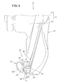
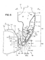
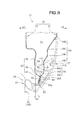
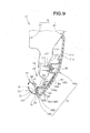
- the door 12 includes a door body 15 openably and closably mounted on the front frame section 41, an exterior member 27 mounted on the door body 15, and a seal member 28 (see Fig. 6 ) mounted on the exterior member 27.
- the door body 15 includes an integral sash 17, and a glass 18 openably and closably guided along the sash 17.
- the door body 15 is a hollow member which comprises an outer door panel 21 and an inner door panel 22.
- the outer door panel 21 and the inner door panel 22 may be formed of any desired material, such as a steel plate, aluminum plate or resin plate.
- the respective edges of the outer door panel 21 and the inner door panel 22 are joined to each other to together constitute a peripheral edge section 163 of the door body 15.
- the edge (outer peripheral edge section or flange) of the outer door panel 21 and the edge (inner peripheral edge section or flange) of the inner door panel 22 are joined to each other.
- a hollow section 23 is defined in the door body 15 by the outer door panel 21 and the inner door panel 22.
- a lower overlapping joint section (inner lower overlapping joint section) 85 and a bulging section (inner bulging section) 87 are formed integrally on a lower section of the inner door panel 22.
- the inner lower overlapping joint section 85 is a lower part of the peripheral edge section of the inner door panel 22.
- the bulging section 87 is formed integrally or continuously with the upper end of the inner lower overlapping joint section 85 and bulges from the inner lower overlapping joint section 85 toward the interior of the vehicle 11 as indicated by arrow al.
- the inner bulging section 87 includes a first bent portion 91, a second bent portion 92 and a curved portion (inner curved portion) 93.
- the inner curved portion 93 has a hole 94 formed through the thickness thereof and having a size to permit passage therethrough of a screw 95.
- the inner door panel 22 has at least one drainage hole (preferably a plurality of drainage holes) 57 formed through the thickness thereof.
- the drainage hole 57 is a small through-hole for discharging water Wa, having entered the interior or hollow section 23 of the door body 15, to the outside.
- the drainage hole 57 is positioned spaced from the edge 54 (lower edge 54) of the door 15 toward the frame section 41 by a distance Es.
- the edge 54 is a lower end part of the peripheral edge section 163 of the door body 15.
- a lower overlapping joint section (outer lower overlapping joint section) 97 and first and second bulging sections (first and second outer bulging sections) 98 and 104 are formed integrally on a lower section of the outer door panel 21.
- the outer lower overlapping joint section 97 is a lower part of the peripheral edge section (flange) of the outer door panel 22.
- the first outer bulging section 98 is formed integrally or continuously with the upper end of the outer lower overlapping joint section 97 and bulges from the outer lower overlapping joint section 97 toward the exterior in the vehicle width direction as indicated by arrow a2.
- the first outer bulging section 98 includes a first bent portion 101, a second bent portion 102 and a first curved portion (first outer curve portion) 103.
- the first outer curve portion 103 has a clipping hole 111 formed therein (see Fig. 7 ).
- the second outer bulging section 104 is formed integrally or continuously with the upper end of the first outer bulging section 98 and bulges from the first outer bulging section 98 toward the exterior in the vehicle width direction as indicated by arrow a2.
- the second outer bulging section 104 includes a third bent portion 105, a fourth bent portion 106, a fifth bent portion 107 and a sixth bent portion 108.
- the fifth bent portion 107 has a plurality of clipping holes 112 formed therein at substantially equal intervals
- the frame section 41 has a door-facing surfaces 167 and a sealing surface 168.
- the door-facing surface 167 and the sealing surface 168 are formed, for example, on the outer surface, in the vehicle width direction, of the side sill garnish 35a.
- the door-facing surface 167 is a surface that is located generally on an extension of the edge 54 (lower edge 54) of the door body 15 and that diagonally faces the edge 54 of the door body 15 when the door 12 is in a closed position.
- the sealing surface 168 is a surface extending from the door-facing surface 167 toward the door opening 161.
- the stealing surface 168 is disposed in such a manner that the seal member 28 contacts the sealing surface 168 when the door 12 is closed in a direction perpendicular to the door opening 161 (i.e., closed in a direction of arrow a1).
- At least a part of the inner peripheral surface of the frame section 41 comprises a slanting wall section 172 inclined from an end 171 of the sealing surface 168 closer to the door opening 161 toward the center of the door opening 161 and toward the interior of the vehicle.
- the end 171 of the sealing surface 168 is located closer to the door-facing surface 173 by a height ⁇ 2 than a start point 173 where the edge 97 of the outer door panel 21 and the edge 85 of the inner door panel 22 start being superposed on each other: Namely, the end 171 of the sealing surface 168 is located lower than the start point 173 by the height ⁇ 2.
- At least a part of the outer peripheral surface of the frame section 41 comprises a design wall section 174 formed continuously with the door-facing surface 167.
- the design wall section 174 of the frame section 41 serves to enhance the outer appearance of the frame section 41, and the outer surface of the design wall section 174 is shaped such that it lies substantially flush with the outer surface 27a of the exterior member 27.
- the exterior member 27 which is also called “lower door garnish", is a member for enhancing design quality of the vehicle 11 and/or protecting the outer surface 53 of the vehicle body 15.
- the exterior member 27 is formed of a material, such as a resin material, softer than the door body 15, i.e. greater in tensile strength than the door body 15.
- the exterior member 27 is superposed and mounted on the outer surface 53 of the door member 15 of the door body 15, i.e. a lower section of the outer surface 53 of the outer door panel and thereby covers at least a part of the external surface 53.
- the first outer bulging section 98 and second outer bulging section 104 of the outer door panel 21 are covered with the exterior member 27.
- the outer surface 27a of the exterior member 27 lies almost continuously with the outer surface 53 of the door 12, i.e. with no substantive gap left between the outer surface 27a and the outer surface 53.
- the exterior member 27 is an integrally molded component part comprising an exterior member body 165 (including an extension section 164), a flange section 184, a bent section 186, an inner wall 188 and a joining flange section 124.
- the exterior member body 165 covers at least a section, e.g. lower section, of the external surface 53 of the outer door panel 21.
- extension section 164 which is a section integrally formed to supplement the exterior member body 165, extends an extension distance ⁇ 1 from the exterior member body 165, along the outer surface 53, outwardly beyond the edge 54 of the door body 15.
- the extension section 164 extends from the exterior member body 165 to near the outer edge of the frame section 41 (i.e., to near the design wall section 174 of the frame section 41).
- the outer surface of the exterior member body 165 and the outer surface of the extension section 164 are substantially identical to the outer surface 27a of the exterior member 27. Further, the reverse surface of the exterior member body 165 and the reverse surface of the extension section 164 are substantially identical to the reverse surface 177 of the exterior member 27. Thus, in the following description, the outer surface of the exterior member body 165 and the outer surface of the extension section 164 will be mentioned with reference character 27a while the reverse surface of the exterior member body 165 and the reverse surface of the extension section 164 will be mentioned with reference character 177, as necessary.
- design surface 27a Because the outer surface 27a of the exterior member 27 and hence the outer surfaces 27a of the exterior member body 165 and the extension section 164 are surfaces influencing the design quality of the vehicle body 11, these surfaces 27a will be collectively referred to as “design surface 27a” as necessary. Because the exterior member body 165 and the extension section 164 have the design surface 27a, they will sometimes be referred to also as “design sections 165 and 164".
- the exterior member body 165 and the extension section 164 are curved to extend to beneath the lower edge 54 along a lower portion of the outer surface 27a of the exterior member 27.
- the flange section 184 extends substantially horizontally from an edge 189 of the exterior member body 165 (edge 189 of the extension section 164) toward the peripheral edge section 163 of the door body 15 (see Fig. 6 ), i.e. toward the interior of the vehicle.
- the flange section 184 has an outer surface that does not substantially influence the design quality of the vehicle 11 (see Fig. 1 ). Because the flange section 184 is a section substantially invisible when the vehicle 11 is viewed sideways, it will be referred to also as "non-design section 184" as necessary. Further, because the edge 189 of the extension section 164 is a boundary between the extension section 164 and the flange section 184, it will be referred to also as "boundary corner portion 189".
- the bent section 186 is a reduced-thickness section formed integrally with the distal end 185 of the flange section 184 and bendable in a thickness direction of the flange section 184.
- the bent section 186 is a section that has a smaller thickness than the flange section 184 and the inner wall 188 and is bendable easily like a hinge. Therefore, the bent section 186 will be referred to also as "reduced-thickness hinge 186" as necessary.
- the bent section 186 extends straight along the distal end 185 of the flange section 184.
- the inner wall 188 is a section formed integrally with the bent section 186 and bendable about the bent section 186 toward the reverse surface 177 of the exterior member body 165 (extension section 164).
- the inner wall 188 extends straight from a front end portion 131 to a rear end portion 132 of the door body 15 shown in Fig. 3 . More specifically, the inner wall 188 includes a wall section 68 formed continuously with the bent section 186, and a lower plate portion 66 formed continuous with the distal end of the wall section 68.
- the lower plate portion 66 (seal backup portion 66), which is of a substantially horizontal plate shape, is located under the lower edge 54 of the door body 15 and has a flat upper surface.
- substantially horizontal means a state where the lower plate portion 66 lies substantially horizontal when the vehicle 11 is in a horizontal position.
- the wall section 68 is a section of a substantially vertical plate shape extending downward from an end, remote from the door body 15, of the lower plate portion 66.
- a surface 71 of the wall section 68 opposite from the reverse surface 177 of the exterior member 27 (i.e., end surface or outer surface 71 of the wall section 68) is provided as a "seal mounting surface 71".
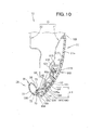
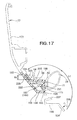
- the joining flange section 124 is a free end section formed at a distal end portion of the inner wall 188 and capable of being joined to the reverse surface 177 of the exterior member body 165. Namely, the joining flange section 124 extends upward from an end, adjacent to the reverse surface of the exterior member 27, of the seal backup portion 66. Further, as shown in Figs. 13 and 17 , the exterior member 27 has at least one rib 129 (preferably a plurality of ribs 129 arranged in a horizontal row) formed on a corner between the lower plate portion 66 and the joining flange section 124.
- the bent section 186 is bent in such a manner that the joining flange section 124 is superposed on and joined to the reverse surface 177 of the exterior member body 165 With the joining flange section 124 joined to the reverse surface 177 of the exterior member body 165 like this, the exterior member body 165, the flange section 184 and the inner wall 188 together constitute a first closed section part 187 of a closed sectional shape.
- the joining flange section 124 is joined to the reverse surface 177 of the exterior member body 165 by adhesive bonding.
- the first closed section part 187 is formed on the reverse surface 177 of the exterior member body 165 in a closed sectional shape and disposed be positioned between the edge 54 of the door body 15 and the door-facing surface 167 when the door 12 is closed.
- the first closed section part 187 includes the lower plate portion 66, the joining flange section 124 and the at least one rib 129.
- the first closed section part 187 has the end surface 71 extending adjacent to an opposite side of the edge 54 of the door body 15 from the reverse surface 177 of the extension section 164, and the end surface 71 comprises the outer surface 71 of the wall section 68.
- the exterior member 27 is mounted on the door body 15 in the following manner. As shown in Figs. 7 , 11 and 13 , the outer door panel 21 has a plurality of clipping holes 112 formed through the thickness thereof. A plurality of lugs (fixing portions) 117 projecting toward the clipping holes 112 are formed on the reverse surface 177 of the exterior member body 165. The plurality of lugs 117 are superposed on the outer door panel 21 and fastened to the clipping holes 112 by means of clops 118, so that the exterior member 27 is mounted on the door body 15.
- the exterior member 27 includes end wall sections 221 and 251, body end joint sections 252 and 253, an evacuation section 255 and a shield wall 257.
- One of the end wall sections 221 extends from one end 215, in the extending direction of the straight bent section 186, of the exterior member body 165 toward the door body 15 (see Fig. 6 ). At least a part (e.g., several dozen percent) of an opening 218 of the first closed section part 187 located near the one end 215 of the exterior member body 165 is covered with the one end wall section 221.
- the other end wall sections 251 extends from the other end 216, in the extending direction of the straight bent section 186, of the exterior member body 165 toward the door body 15 (see Fig. 6 ). At least a part (e.g., several dozen percent) of an opening 248 of the first closed section part 187 located near the other end 216 of the exterior member body 165 is covered with the other end wall section 251.
- the body end joint sections 252 and 253 are provided to join the exterior member body 165 to the door body 15.
- the body end joint sections 252 and 253 are joined to the outer surface 53 of the outer door panel 21, for example, by means of adhesive tapes 254.
- the adhesive tapes 254 are, for example, double-sided tapes each of which comprises a thin film-like base sheet having adhesive layers formed on both surfaces thereof.
- the evacuation section 255 is formed in such a manner as to bypass the body end joint sections 252 and 253. Namely, the evacuation section 255 is located to prevent the inner wall 188 from interfering with the body end joint sections 252 and 253 as the inner wall 188 is bent about the bent section 186 as noted above.
- the shield wall 257 is provided to close up a gap between the reverse surface 177 of the exterior member body 165 and the evacuation section 255.
- the exterior member 27 is curved to be slightly concaved or recessed in the vehicle width direction.
- a spaced apart distance ⁇ f, ⁇ r from the edge 189 to the bent section 186 of the exterior member body 165 differs among portions of the exterior member body 165. Namely, the spaced-apart distance ⁇ f, ⁇ r gradually decreases in a direction from the opposite ends 215 and 216, in the front-rear direction of the vehicle, toward the middle in the front-rear direction.
- the bent section 186 and the inner wall 188 are provided only in portions 187a and 187b of the exterior member body 165 where the spaced-apart distance ⁇ f, ⁇ r is greater than a predetermined distance ⁇ 1, ⁇ 2.
- An inner wall member 115 that is a separate member from the inner wall 188 is mounted on the reverse surface 177 of the remaining portion 195 where the bent section 186 and the inner wall 188 are not provided.
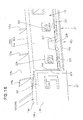
- Fig. 12(a) shows, from the side of the reverse surface 177, the inner wall member 115 mounted on the exterior member 27, and Fig. 12(b) shows, from the side of the reverse surface 177, the inner wall member 115 dismounted or detached from the inner wall member 115.
- the inner wall member 115 is a component part integrally molded of resin, which includes an inner wall 188a, a joining flange section 124a, a plurality of seal pressing sections 129a, an inner-wall-door joint section 237 and a rib 241.
- the inner wall 188a of the inner wall member 115 which is substantially the same in construction as the inner wall 188 of the exterior member 27, includes a seal backup portion 66a and a wall section 68a.
- the seal backup portion 66a is substantially the same in construction as the seal backup portion 66 of the exterior member 27, and the wall section 68a is substantially the same in construction as the wall section 68 of the exterior member 27.
- the joining flange section 124a is substantially the same in construction as the joining flange section 124 of the exterior member 27.
- the plurality of seal pressing sections 129a (ribs 129a) are substantially the same in construction as the plurality of seal pressing sections 129 of the exterior member 27.
- respective lengths Lr of the plurality of seal pressing sections 129a are set to gradually decrease as the spaced-apart distance ⁇ f, ⁇ r from the edge 189 of the exterior member body 165 to the bent section 186 gradually decreases in a direction from the opposite ends 215 and 216 in the front-rear direction of the vehicle toward the middle in the front-rear direction.
- a height Hr of the seal pressing sections 129 and 129a is set lower than a height of an outer-surface sealing section 64; for example, the height Hr is set at about 60% of the height of the outer-surface sealing section 64.
- the inner wall member 115 and the exterior member body 165 together constitute a second closed section part 197 of a closed sectional shape.
- the first closed section part 187 and the second closed section part 197 extend in a series along the bent section 186. More specifically, the first closed section part 187 and the second closed section part 197 extend in a series in the front-rear direction of the vehicle body.
- the second closed section part 197 is substantially the same in closed sectional shape and size as the first closed section part 187.
- a combination of the first closed section part 187 and the second closed section part 197 constitutes a "closed section part 166".
- the inner-wall-door joint section 237 is a section that extends upward from the upper end of the joining flange section 124a and is superposed on and joined to the reverse surface 177 of the exterior member body 165.
- the rib 241 is formed to edge the outer periphery of the inner-wall-door joint section 237.
- the impact load is dispersed by the rib 241 throughout the exterior member 27.
- the instant embodiment can increase the strength of the exterior member 27 and inner wall member 115.
- the exterior member 27 includes two separate-member joining mechanisms 203 that join the inner wall member 115 to the exterior member body 165 (including the extension section 164) and that are located near the superposition sections 201.
- Each of the separate-member joining mechanisms 203 includes the superposition section 201, a locking claw 205, a locking surface 206, an engagement section 207, first and second U-shaped restriction sections 224 and 225, first and second abutment restriction sections 226 and 227, a locking section 231 and an engaging claw section 232.
- the locking claw 205 projects from the flange section 184 toward the inner wall member 115.
- the locking surface 206 is one surface of the locking claw 205 and faces the reverse surface 177 of the exterior member body 165.
- the engagement section 207 is formed on the inner wall member 115 for locking engagement by the locking surface 206. More specifically, the engagement section 207 is formed in a shape recessed from a surface of the inner wall member 115 abutting against the locking surface 206 toward the reverse surface 177 of the exterior member body 165.
- the inner wall member 115 is joined to the exterior member body 165 by being sandwiched between the reverse surface 177 of the exterior member body 165 and the locking surface 206.
- the engagement section 207 may be of a mere flat shape or may be in the form of a projection engageable by the locking claw 205.
- the first and second U-shaped restriction sections 224 and 225 each project inwardly in the vehicle width direction from the reverse surface 177 of the extension section 164 and have a substantially U-shaped horizontal groove opening to the distal end thereof.
- the first and second abutment restriction sections 226 and 227 are each formed in a horizontal bar shape on the wall section 68a of the inner wall member 115 and are fitted in the horizontal grooves of the first and second U-shaped restriction sections 224 and 225, respectively.
- the above-mentioned locking section 231 (opening locking section 231) is in the form of a through-hole formed in the superposition section 201 of the inner wall member 115.
- the above-mentioned engaging claw section 232 projects from the wall section 68 of the exterior member 27 into the first closed section part 187 and has a claw at its distal end.
- the superposition section 201 is fitted in the first closed section part 187, but also the engaging claw section 232 is engaged by the locking section 231 (i.e., by the edge of the through-hole 231).
- the reason why the inner wall member 115 has the superposition sections 201 is as follows. As shown in Figs. 12(a) and 12(b) , the inner wall member 115 is fitted between respective one ends 245 and 246 of the two first closed section parts 187. Slight gaps might exist between the opposite ends 243 and 244, in the front-rear direction, of the inner wall member 115 and the ends 245 and 246 of the two first closed section parts 187. In order to increase the strength of the exterior member 27 with the first and second closed section parts 187 and 197, it is preferable that the first and second closed section parts 187 and 197 extend substantially continuously with each other.
- the inner wall member 115 has the superposition sections 201 extending from the opposite ends 243 and 244 into the two first closed section parts 187.
- the second closed section part 197 can be positioned relative to the first closed section parts 187.
- the first and second closed section parts 187 and 197 are joined to one another sufficiently firmly by means of the superposition sections 201 and separate-member joining mechanisms 203.
- the first and second closed section parts 187 and 197 extend substantially continuously with each other to constitute the single "closed section part 166".
- the exterior member 27 can have a sufficient strength.
- the external force When external force (load) has acted on the inner wall member 115, such as when the door 12 has been closed, the external force transmits from the inner wall member 115 to the first closed section parts 187 by way of the superposition sections 201 and separate-member joining mechanisms 203. Because the first and second closed section parts 187 and 197 are joined to one another sufficiently firmly by means of the superposition sections 201 and separate-member joining mechanisms 203, relative positional deviation due to the external force can be prevented.
- the exterior member 27 is provided in the same state as molded, i.e. with the inner wall 188 opened relative to the exterior member body 165.
- adhesive agent 228 is applied to the joining flange section 124a of the inner wall member 115 shown in Fig. 18 .
- first and second abutment restriction sections 226 and 227 are fitted in the horizontal grooves of the first and second U-shaped restriction sections 224 and 225 as shown in Fig. 18 with the engagement section 207 engaged by the locking claw 205 shown in Fig. 19 .
- the entire inner wall member 115 is turned toward the reverse surface 177 of the exterior member 27 (i.e., in a direction of arrow b1),
- the first and second abutment restriction sections 226 and 227 are fitted in the horizontal grooves of the first and second U-shaped restriction sections 224 and 225, and substantially simultaneously therewith, the joining flange section 124a is adhered to the reverse surface 177 by means of the adhesive agent 228.
- the second closed section part 197 is formed.
- adhesive agent 228 is applied to the joining flange section 124 shown in imaginary line in Fig. 17 .
- an adhesive tape may be attached to the joining flange 124 without the adhesive agent 228 being used.
- the inner wall 188 is turned about the bent section 186 toward the reverse surface 177 of the exterior member 27 (i.e., in the direction of arrow b1), during which the engaging claw section 232 is brought into engagement by the locking section 231 (i.e., by the edge of the through-hole 231). Simultaneously, the inner wall 188 is brought into superposition on the superposition section 201 of the inner wall member 115.
- the joining flange section 124 is superposed on the reverse surface 177 by the inner wall 188 being further turned.
- the joining flange section 124 is adhered to the reverse surface 177 by means of the adhesive agent 228.
- the first closed section part 187 is formed.
- the superposition section 201 is fitted in the first closed section part 187 and mechanically joined to the latter.
- An upper portion of the inner wall member 115 is mounted on the exterior member 27 in the following manner.
- one lug (fixing section) 119 is formed on the reverse surface 177 of the exterior member body 165 and protrudes into the door body 15, i.e. toward the inner wall member 115.
- the inner wall member 115 has a second fastening section 128 recessed to allow the lug 119 to be fitted therein.
- the second fastening section 128 is superposed on and fastened to the distal end surface of the lung 119 by means of a screw 121. In this manner, the inner wall member 115 is mounted on the exterior member 27.
- the inner wall member 115 is mounted on the door body 15 in the following manner. As shown in Figs. 6 , 7 and 13 , the outer door panel 21 has the one clipping hole 111 formed through the thickness thereof. A first fastening section 127 is formed on the reverse surface of the inner wall member 115 and protrudes toward the clipping hole 111. The first fastening section 127 is superposed on and fastened to the clipping hole 111 by means of a clip 122 and a screw 95. In this manner, the inner wall member 115 is mounted on the door body 15.
- the exterior member 27 and the inner wall member 115 are formed by separate resin-molding molds.
- a gate is formed in a cavity portion for forming the flange section 184, and this gate is in communication with a flow path (sprue) into which resin flows directly from a nozzle of an injection molding machine.
- sprue a flow path into which resin flows directly from a nozzle of an injection molding machine.
- the seal member 28 (door seal 28) is capable of contacting and sealing the frame section 41, defining the door opening 161, when the door 12 is closed.
- the seal member 28 (door seal 28), which is a member elongated in the front-rear direction of the vehicle body along the exterior member 27 (see Fig. 3 ), is integrally formed of a material, such as rubber, having elasticity or flexibility.
- the seal member 28 is attached to the extension section 164 of the exterior member 27, i.e. to the end surface 71 (seal mounting surface 71) of the closed section part 166.
- the seal member 28 includes a slant section 58, a drainage sealing section 62, an outer-surface sealing section 64, a seal mounting section 72 and a lower half section (seal's lower half section) 77.
- the slant section 58 is located closer to the frame section 41 than the drainage hole 57 when the door 12 is closed (in the closed position).
- the slant section 58 is opposed to the drainage hole 57 and slants downward toward the extension section 164. Namely, the slant section 58 slants in the thickness direction of the door body 15 in such a manner that its upper end is located farther from the door body 15 than its lower end.
- the slant section 58 is opposed to the drainage hole 57, but also at least its portion located closer to the interior of the vehicle than the drainage hole 57 slants toward the interior of the vehicle as its height increases, as shown in Fig. 6 .
- the slant section 58 slants in such a manner that its upper end (free end) is located near the end 171 of the sealing surface 168 closer to the door opening 161 when the door 12 is in the closed position.
- the slanting surface of the slant section 58 lies substantially on an extension of the slanting surface of a slanting wall section 172.
- the drainage sealing section 62 (projecting section 62) connects integrally to the slant section 58.
- the drainage sealing section 62 extends from the lower end of the slant section 58 toward the door body 15 and extends beneath the drainage hole 57 to the lower edge 54 of the door body 15.
- the drainage sealing section 62 extends from a seal section 81, along the upper surface of the seal backup portion 66, 66a (lower plate portion 66, 66a), to the rib 129, 129a.
- the reverse surface 65 of the drainage sealing section 62 (see Fig. 9 ) is supported by being superposed on the seal backup portion 66, 66a.
- the outer-surface sealing section 64 extends upward from the distal end of the drainage sealing section 62 (extension section 62). Near the lower end 54 of the door body 15, the outer-surface sealing section 64 is sandwiched by the outer surface 53 of the door body 15 and the rib 129, 129a of the exterior member 27.
- the outer-surface sealing section 64 connects to the drainage sealing section 62 and is located outwardly (in a direction of arrow a2 in Fig. 6 ) of the lower edge 54 of the door body 15 and kept in firm contact with the outer surface 53a near the lower edge 54 by being pressed by the exterior member 27.
- the seal half section 77 (another slant section 77) extends internally from the lower end 75 of the seal mounting section 72 to the upper end (free end) of the slant section 58 while bulging downwardly.
- the lower end 75 of the seal mounting section 72 is kept in abutting engagement with the lower end of the wall section 68 of the exterior member 27.
- the lower half section 77 extends from a portion, located downward of a corner portion 73a, of the seal mounting section 72 (i.e., from the lower end 75 of the seal mounting section 72) obliquely upward toward the end 171 of the sealing surface 168 closer to the door opening 161 and thereby integrally connects to the upper end of the slant section 58.
- the seal section 81 for contacting and sealing the frame section 41 of the door opening 161 is a hollow seal section having a hollow sectional shape, i.e. in the form of a tubular seal structure.
- the hollow seal section 81 integrally comprises the slant section 58, the seal mounting section 72 and the lower half section 77.
- the hollow seal section 81 extends from the front end portion 131 to the rear end portion 132 of the door body 15.
- the: hollow seal section 81 elastically deforms by being pressed against the sealing surface 168 so that it can firmly contact and seal the sealing surface 168, as shown in Fig. 6 .
- the hollow seal section 81 is open at its front end 134 as shown in Figs. 2 and 4 and closed at its rear end 135 as shown in Fig. 5 . Further, as shown in Figs. 2 to 5 , drainage water Wd from the interior of the door body 15 can be discharged to the outside through the front end 134 and rear end 135 of the seal member 28 as indicated by arrow a4 and arrow a5.
- the seal mounting section 72 is a section of a vertical plate shape extending along the seal mounting surface 71 and superposed and mounted on the seal mounting surface 71.
- the seal mounting section 72 has its upper end formed integrally with a base portion 73 of the drainage sealing section 62 merging with the lower end of the slant section 58.
- the slant section 58 extends upward from the corner portion 73 (base portion 73) between the seal mounting section 72 and the drainage sealing section 62, as shown in Fig. 10
- the seal member 28 is mounted to the closed section part 166 (first and second closed section parts 187 and 197) by means of at least one seal fixing member 141, preferably a plurality of seal fixing members 141.
- Each of the seal fixing members 141 is, for example, in the form of a clip that is partly inserted in the interior of the closed section part 166 to be engaged by the closed section part 166.
- the seal mounting surface 71 of the closed section part 166 has a plurality of clipping holes 234, 238 formed therein.
- the clipping holes 234, 238 are formed substantially in a series in the front-rear direction of the vehicle.
- a plurality of the clipping holes 234 are formed through the wall thickness thereof.
- a plurality of the clipping holes 238 are formed through the wall thickness thereof.
- the seal member 28 has a recessed section 137 in its surface facing the seal mounting surface 71.
- the seal member 28 has a plurality of clipping holes 138 ( Fig. 10 ) formed through the thickness of the recessed section 137.
- the plurality of clipping holes 138 are each formed in a size capable of grasping the clip 141. Namely, a plurality of the clips 141 are fitted in the respective clipping holes 234, 238, so that the seal member 28 is mounted to the closed section part 166.
- the other structural elements than the seal member 28A are similar to those in the first embodiment shown in Figs. 1 to 24 and will not be described here to avoid unnecessary duplication.
- a seal section 81A of the seal member 28A for contacting and sealing the frame section 41 of the door opening 161 is formed in a substantially U sectional shape opening upward.
- the seal section 81A integrally comprises a slant section 58A, the seal mounting section 72 and the lower half section 77. As the door 12 is closed, the hollow seal section 81A elastically deforms by being pressed against the sealing surface 168 so that it can firmly contact and seal the sealing surface 168
- the upper opening of the seal section 81A faces the drainage hole 57 when the door is in the closed position.
- the inner surface 58A of the seal section 81A is located closer to the frame section 41 than the drainage hole 57.
- the inner surface 58A is opposed to the drainage hole 57 and slants downward toward the extension section 164.
- the sinner surface 58A slants in the thickness direction of the door body 15 in such a manner that its upper end is located farther from the door body 15 than its lower end.
- the inner surface 58A of the seal section 81A will be referred to as "slant section 58A".
- the slant section 58A is opposed to the drainage hole 57, but also at least its portion located closer to the interior of the vehicle than the drainage hole 57 slants toward the interior of the vehicle as its height increases.
- the slant section 58A slants in such a manner that its upper end (free end) is located near the end 171 of the sealing surface 168 closer to the door opening when the door 12 is in the closed position.
- the slanting surface of the slant section 58A lies substantially on an extension of the slanting surface of the slanting wall section 172.
- drainage water Wa discharged via the drainage hole 57 can be directed in a direction of arrow a3.
- a come-off preventive protrusion 154 is formed on the upper end edge of the outer-surface sealing section 64.
- the second embodiment of the vehicle door assembly 40A can achieve the same behavior and advantageous benefits as the above-described first embodiment of the vehicle door assembly 40A.
- the second embodiment of the vehicle door assembly 40A is advantageous in that the seal member 28A can be manufactured with ease and that it can be reduced in weight.
- the door in the vehicle door assembly 40, 40A of the present invention is not limited to application as a side door, such as the front door 12 or rear door 46, and it may be a tail gate, bonnet (hood) or the like. Further, the door in the vehicle door assembly 40, 40A of the present invention is not limited to a swing door and may be a slide door.
- a place on which the exterior member 27 is mounted is not limited to a lower section of the outer surface of the door body 15 and may be a rear or upper section of the outer surface of the door body 15.
- the present invention is not limited to the aforementioned construction where the inner wall member 115 is disposed on a middle portion, in the front-rear direction of the vehicle, of the exterior member 27, and the inner wall member 115 may be disposed on a front or rear portion in the front-rear direction of the vehicle, of the exterior member 27. Furthermore, such inner wall members 115 may be disposed on a plurality of portions of the exterior member 27.
- the present invention is not so limited, and the "mechanical joint” may be a joint made by screwing a bolt into a nut (i.e., joint by a screw), joint by a rivet, a joint by a tack, such as a clip engaged without a thread being formed in a shaft thereof, a joint using press fitting, a joint by a band using a band-shaped steel plate and steel wire, a joint by a spring, a joint by a stop ring, or a joint by a sandwiching metal member like a slip or clamp.
- the vehicle door assembly 40, 40A of the present invention is well suited for application to automotive vehicles.
Landscapes
- Engineering & Computer Science (AREA)
- Mechanical Engineering (AREA)
- Civil Engineering (AREA)
- Structural Engineering (AREA)
- Seal Device For Vehicle (AREA)
- Body Structure For Vehicles (AREA)
Description
- The present invention relates to a door assembly for a vehicle or vehicle door assembly having an exterior member provided on the outer surface of a vehicle door for opening and closing a door opening formed in a vehicle body.
- In order to enhance design quality of vehicles and/or protect the outer surfaces of the vehicles, various exterior members are provided on parts of the upper surfaces of vehicle bodies. For similar purposes, exterior members are sometimes provided on the outer surfaces of vehicle doors as well. Techniques for providing an exterior member on the outer surface of a vehicle door are disclosed in
Patent Literature 1 andPatent Literature 2. According to each ofPatent Literature 1 andPatent Literature 2, the vehicle door on which the exterior member is provided is a side door for opening and closing a get-in/out opening (door opening) formed in the vehicle body. A lower section of the outer surface of the side door is covered with the exterior member formed of resin. - Such conventionally-known vehicle door assemblies have the following three room for improvement.
- The first room for improvement is as follows. The get-in/out opening (door opening) is formed in the vehicle body in a given size in accordance with design of the vehicle. Further, it is preferable that the get-in/out have a large size to allow a passenger to get in and out to and from the vehicle. In many cases, the side door is manufactured in a different plant from the vehicle body by use of existing manufacturing facilities. In order to manufacture a large-size side door, limitations of capacities of the manufacturing equipment, for example, are often encountered. In a case where the vehicle is designed so that a large get-in/out opening is closed with a relatively small side door, arrangements have to be made such that no gap is formed in a surface direction of the door between a frame section defining the get-in/out opening and the lower end of the side door. In order to avoid such a gas, it may be conceivable to expand downward an inner panel of the door panel. However, because the door increases in weight in such a case, there is room for improvement with a view to reducing the weight of the vehicle.
- Further, in the vehicle door disclosed in
Patent Literature 2, a seal member seals between a frame section defining the get-in/out opening and an edge of the side door. When the door is closed (in a closed position), the seal member is sandwiched between the frame section and the edge of the side door. Thus, reactive force acts on the edge of the side door due to the sandwiching of the seal member. If a gap exists in the surface direction of the door, no seal member can be provided on the edge of the side door. - The second room for improvement is as follows. The exterior member disclosed in
Patent Literature 2 includes: a panel-shaped exterior member body covering a lower section of the outer surface of the side door; a flange section extending from the lower end of the exterior member body toward the lower edge of the side door; a panel-shaped reduced-thickness section formed integrally with the distal end of the flange section; and an inner wall formed integrally with the exterior member body via the small-thickness section. The reduced-thickness section is a section bendable in the thickness direction and generally called a reduced-thickness hinge. The inner wall is bent inward about the reduced-thickness hinge toward the reverse side of the exterior member body and joined to the reverse surface. Thus, on the lower end of the exterior member body, a closed section part having a closed sectional shape is formed with the exterior member body, the flange section and the inner wall. - Generally, the resin-made exterior member is formed by a resin-molding mold that has a gate (feed opening) formed therein for feeding molten resin into a cavity. Thus, there would be left an unwanted mark of the gate on the molded exterior member; such a mark is positioned on the reverse surface of the flange section so that it is invisible from outside the exterior member. Further, the above-mentioned inner wall is located across the reduced-thickness hinge from the exterior member body and the flange section. Because a narrowed space is defined between the flange section and the inner wall, a flow, between the flange section and the inner wall, of the molten resin fed through the gate tends to be limited. Thus, in order to smooth the flow of the molten resin, it is preferable to provide the gate in a portion of the cavity having a relatively large space, e.g. a cavity portion corresponding to the flange section.
- The vehicle doors are formed in various shapes in accordance with design of the vehicles, and a variety of shapes are required of the exterior members depending on the shapes of the vehicle doors. In some cases, the exterior member may be curved to be slightly concave or recessed inward in the vehicle width direction, while the reduced-thickness hinge is formed straight in such a manner as to be bendable. Therefore, a width of the flange section, i.e. a distance from the reduced-thickness hinge to the lower end of the exterior member body, would greatly differ depending on the curved shape of the exterior member.
- In the case where the exterior member is curved to be slightly concave or recessed inward in the vehicle width direction as above, the flange section has a minimum width at its middle portion in the longitudinal direction of the door (i.e., front-rear direction of the vehicle body). Thus, the gate sometimes may not be able to be provided on the flange-section-corresponding cavity portion of the cavity in the resin-molding mold. In such a case, there is no other choice but to provide the gate in a cavity portion corresponding to the exterior member body located greatly remote from the reduced-thickness hinge. Namely, there is room for improvement in order to allow the molten resin to flow uniformly throughout the entire range of the cavity. Therefore, limitations would be encountered in increasing a strength of the exterior member.
- The third room for improvement is as follows. Generally, the bodies of the vehicle side doors have a drainage hole for discharging water having entered the interior of the door body, as known from
Patent Literature 2 and Patent Literature 3. - In the vehicle side door disclosed in
Patent Literature 2, the drainage hole and the seal member are provided in and on the lower end of the door body, respectively, and the lower section of the outer surface of the side door is covered with the exterior member. The exterior member is formed in a gutter shape such that it includes a portion positionally corresponding to the drainage hole and it covers the lower end of the lower end of the door body. More specifically, the drainage hole is formed in the bottom of the exterior member, and the seal member is a weather strip that contacts and seals the frame section of the get-in/out opening when the side door is closed and that is located closer to the interior of the vehicle than the exterior member. - Further, the vehicle side door disclosed in Patent Literature 3 includes the drainage hole, a weather strip and a seal member provided in and on the lower end of the door body. The weather strip is a member that is located closer to the interior of the vehicle than the exterior member and that contacts and seals a frame section of the get-in/out opening when the side door is closed. The seal member (parting seal), which is formed in a tubular shape and located immediately beneath the drainage hole, has a communication hole capable of introducing thereinto water discharged via the drainage hole.
- However, the techniques disclosed in
Patent Literature 2 and Patent Literature 3 are disadvantageous in that, of the vehicle is designed so that a large get-in/out opening is closed with a relatively small side door, a gap would be formed between the frame section defining the get-in/out opening and the lower end of the side door. Due to such a gap, no seal member can be provided on the lower edge of the side door. Besides, the drainage hole formed in the lower end of the side door would be located away from the frame section. Thus, arrangements have to be made to prevent water, discharged via the drainage hole, from entering the interior the door through the gap. - If the seal member employed in any one of the vehicle doors disclosed in
Patent Literature 1 andPatent Literature 2 is mounted as-is below the drainage hole and in such a manner as to cover the drainage hole, a distance from the drainage hole to the seal member would increase. Thus, the frame section would get wet with water discharged via the drainage hole. Particularly, in cold weather regions, the water having wetted the frame section tends to easily freeze, so that the seal member may adhere to (freeze to) the frame section. Therefore, arrangements have to be made to secure enough durability of the seal member. -
- Patent Literature 1: Japanese Patent Application Laid-Open Publication No.
2007-186093 - Patent Literature 2: Japanese Utility Model Publication No.
SHO-64-3687 - Patent Literature 3: Japanese Patent Application Laid-Open Publication No.
HEI-8-142673 -
US 2001/0012388 A1 shows a vehicle door assembly in accordance with the preamble ofclaim 1. - It is an object of the present invention to provide a technique which can increase the durability of the seal member that seals between the frame section of the get-in/out opening and the door body.
- The invention provides a vehicle door assembly according to
claim 1. - The vehicle door assembly includes a vehicle door for opening and closing a get-in/out opening of a vehicle body, the vehicle door comprising: a door body of a hollow sectional shape; an exterior member mounted on a lower section of the outer surface of the outer door body and including an extension section extending downward beyond the lower edge of the door body; and a seal member mounted on the extension section and capable of contacting and sealing a frame section, defining the get-in/out opening, when the door is closed. The door body has at least one drainage hole for discharging water having entered the interior of the door body, the seal member includes a slant section located closer to the frame section than the drainage hole when the door is closed, and the slant section is opposed to the drainage hole and slants downward toward the extension section.
- The drainage hole is located closer to the frame section than the lower edge of the door body when the door is closed, the seal member includes a drainage sealing section connecting integrally to the slant section, and the drainage sealing section extends from the lower end of the slant section in a direction toward the door body and extends beneath the drainage hole to the lower edge of the door body.
- The seal member includes an outer-surface sealing section extending upward from the distal end of the drainage sealing section, and, the outer-surface sealing section is sandwiched between the outer surface of the outer door panel and the exterior member near the lower edge of the door body.
- The exterior member includes a seal backup portion having a flat upper surface for supporting thereon the reverse surface of the drainage sealing section.
- The seal backup portion includes a wall section extending downward from an end, located remote from the door body, of the seal backup portion, a surface of the wall section opposite from the reverse surface of the extension section being provided as a seal mounting surface, the seal member includes a seal mounting section shaped to extend along the seal mounting surface, and the seal mounting section is superposed on and mounted on the seal mounting surface.
- Preferably, the seal mounting section has an upper end formed integrally with a base portion of the drainage sealing section merging with the lower end of the slant section.
- Preferably, of the seal member, a seal section for contacting and sealing the frame section is a hollow seal section having a hollow sectional shape, and the hollow seal section is formed integrally to integrally include the slant section, the seal mounting section and a lower half section extending from the lower end of the seal mounting section to the upper end of the slant section.
- Preferably, the exterior member includes: a joining flange section extending upward from an end, adjacent to the reverse surface of the exterior member, of the seal backup portion and joined to the reverse surface of the exterior member; and at least one rib formed on a corner between the seal backup portion and the joining flange section. The seal member includes an outer-surface sealing section extending upward from the distal end of the drainage sealing section, and the outer-surface sealing section is sandwiched by the outer surface of the door body and the rib near the lower edge of the door body.
- According to the invention, the door body has the one drainage hole for discharging water having entered the interior of the door body. The exterior member is mounted on a lower section of the outer surface of the door body and has the extension section extending downward beyond the lower edge of the door body. The seal member is mounted on the extension section, and it contacts and seals the frame section of the get-in/out opening when the door is closed. The seal member includes the slant section located closer to the frame section than the drainage hole when the door is closed, and the slant section is opposed to the drainage hole and slants downward toward the extension section.
- The flowing direction of drainage water discharged to the outside via the drainage hole is regulated by the slant section when the door is in the closed position. Namely, the slant section can regulate the drainage water flowing direction so that the drainage water does not flow toward the interior of the vehicle beyond the seal member. Besides, because the slant section slants downward toward the extension section, it can direct the drainage water away from the frame section of the get-in/out opening. The drainage water is directed by the slant section to flow to the drainage sealing section, from which it is discharged to a road surface. Thus, when the door is in the closed position, the present invention can prevent the drainage water from flowing beyond the seal member and accumulating and freezing between the seal member and the get-in/out opening. Because the seal member can be prevented from adhering to (freezing to) the frame section of the get-in/out opening due to freezing of the drainage water in the aforementioned manner, the present invention allows the seal member to have an increased durability.
- Further, the slant section, the drainage sealing section and the door body can together constitute a flow path of a trough shape. Thus, water discharged via the drainage hole can be directed by the slant section, the drainage sealing section and the door body so that it is discharged from a predetermined location. As a result, the present invention can minimize soilage of a lower section of the frame section (e.g., side sill) defining the get-in/out opening.
- Further, it is possible to prevent water, discharged via the drainage hole, from leaking from between the lower edge of the door body and the drainage sealing section. Further, because the exterior member does not directly hit the outer surface of the door body, generation of hitting sound can be avoided.
- Further, the reverse surface of the drainage sealing section is supported on the seal backup portion having a flat upper surface. Thus, the drainage sealing section can be retained in a flat posture. Thus, the present invention allows the drainage water, directed from the slant section, to be promptly discharged to the outside without accumulating in the drainage sealing section.
- Further, the seal member can be mounted to a substantially vertical wall section from inside or outside the vehicle, and thus, the operation for mounting the seal member can be facilitated. When the seal member has been pressed against the frame section defining the get-in/out opening, force input from the seal member can be received and dispersed by a surface of the wall section, so that undesired inclination and movement in the up-down direction of the seal member can be prevented.
- Further, the seal mounting section has an upper end formed integrally with the base portion of the drainage sealing section merging with the lower end of the slant section. Thus; when the seal member has been pressed against the frame section defining the get-in/out opening, reactive force produced in the seal member can be dispersed by the base portion having a great strength, so that deflection of the slant section can be suppressed.
- Furthermore, the provision of the hollow seal section can increase sealability between the seal member and the frame section defining the get-in/out opening. An inclination angle of the slanting surface of the slant section can be made close to the vertical angle as compared to that of a lip seal. Thus, even in case water accumulates in a corner between the drainage sealing section and the slant section, the water can be made hardly visible. In other words, the accumulated water can be made unnoticeable and invisible.
- Furthermore, the rib is formed on the corner between the seal backup portion and the joining flange section. The provision of such a rib can restrain deformation of the seal backup portion and the joining flange section. Particularly, the provision of the rib can prevent the joining flange section from falling down in the direction where the corner changes in angle. Further, using the rib, the outer-surface sealing section can be sandwiched between the rib and the outer door panel. As a result, the outer-surface sealing section can be retained reliably by the door.
-
-
Fig. 1 is a side view showing principal sections of a vehicle provided with a first embodiment of a vehicle door assembly of the present invention; -
Fig. 2 is a perspective view taken in the direction ofarrow 2 ofFig. 1 ; -
Fig. 3 is a view showing front and rear doors ofFig. 1 from inside the vehicle; -
Fig. 4 is a view taken in the direction ofarrow 4 ofFig. 3 ; -
Fig. 5 is a view taken in the direction ofarrow 5 ofFig. 3 ; -
Fig. 6 is a sectional view taken along line 6 - 6 ofFig. 1 ; -
Fig. 7 is an exploded side view of a lower section of a front door and an exterior member shown inFig. 1 ; -
Fig. 8 is a sectional view taken along line 8 - 8 ofFig. 7 ; -
Fig. 9 is a sectional view taken along line 9 - 9 ofFig. 7 ; -
Fig. 10 is a sectional view taken along line 10 - 10 ofFig. 7 ; -
Fig. 11 is a sectional view taken along line 11 - 11 ofFig. 7 ; -
Fig. 12 is a view showing the exterior member ofFig. 7 from a reverse side thereof, which is particularly explanatory of an assembled state and an exploded state of an inner wall member; -
Fig. 13 is a perspective view of the exterior member and the inner wall member in the assembled state; -
Fig. 14 is a view taken in the direction ofarrow 14 ofFig. 12 ; -
Fig, 15 is a view showing in enlarged scale a section encircled at 15 inFig. 13 ; -
Fig, 16 is a view showing in enlarged scale a section encircled at 16 inFig. 13 ; -
Fig. 17 is a sectional view taken along line 17 - 17 ofFig. 16 ; -
Fig. 18 is a sectional view taken along line 18 - 18 ofFig. 16 ; -
Fig. 19 is a sectional view taken along line 19 - 19 ofFig. 16 ; -
Fig. 20 is a perspective view taken in the direction of arrow 20 ofFig. 12 ; -
Fig. 21 is a perspective view taken in the direction ofarrow 21 ofFig. 12 ; -
Fig. 22 is a perspective view taken in the direction ofarrow 22 ofFig. 12 ; -
Fig. 23 is a view taken in the direction ofarrow 22 ofFig. 22 ; -
Fig. 24 is a perspective view taken in the direction of arrow 24 ofFig. 22 ; and -
Fig. 25 is a sectional view showing, from the front of the vehicle, a second embodiment of the vehicle door assembly of the present invention. - A first embodiment of a vehicle door assembly of the present invention will be described with reference to
Figs. 1 to 24 . As shown inFig. 1 , avehicle 11 to which is applied the first embodiment of the vehicle door assembly of the present invention is a so-called four door vehicle having left and rightfront doors 12 and left and rightrear doors 46. - Left and
right door openings 161 and left andright door openings 162 are formed in front and rear sections, respectively, of left and right side surfaces 13a of avehicle body 13. The left and right door openings (get-in/out opening) 161 and left and right door openings (get-in/out opening) 162 are each for a passenger to get in and out of thevehicle 11. The left andright door openings 161 in the front section of thevehicle body 13 are opened and closed by the left and rightfront doors 12, while the rear left andright door openings 162 in the rear section of thevehicle body 13 are opened and closed by the left and rightrear doors 46. - On the left and right side surfaces 13a of the
vehicle body 13 are provided left andright frame sections 41 defining the left andright door openings 16 in the front section of the vehicle body 13 (get-in/out opening defining front frame sections 41) and left andright frame sections 42 defining the left andright door openings 162 in the rear section of the vehicle body 13 (get-in/out opening defining rear frame sections 42). - The left and right
front doors 12 are openably/closably mounted on the left and rightfront frame sections 41 via not-shown hinges. The left and rightrear doors 46 are openably/closably mounted on the left and rightrear frame sections 42 via not-shown hinges. The left and rightfront doors 12 and the left and rightrear doors 46 are side doors that are oriented in a generally vertical direction when they are closing thecorresponding door openings - The left and right
front frame sections 41 comprise left and rightfront pillars 33, left and right center pillars, and left andright side sills 35. The left and rightrear frame sections 42 comprise left andright center pillars 34, left and right rear pillars (not shown), left and right roof rails (not shown), and the left andright side sills 35. - Hereinafter, the left and right
front frame sections 41 will sometimes be referred to collectively as "front frame section 41", and the left and rightrear frame sections 42 will sometimes be referred to collectively as "rear frame section 41". - The left and right
front doors 12, the left and rightrear doors 46, the left and rightfront frame sections 41 and the left and rightrear frame sections 42 together constitute the "vehicle door assembly 40". - As shown in
Figs. 1 and6 , at least outer surfaces, in the vehicle width direction, of the left andright side sills 35 is covered with left and rightside sill garnishes 35a (side sill covers 35a). Thus, the left and right side sill garnishes 35a are substantially parts of the left andright side sills 35. The following description will be given assuming that the left and right side sill garnishes 35a are parts of the left andright side sills 35. - The following describe in detail the left front door 12 (side door 12). The
fright front door 12 will not be detailed here because it is of the same construction as the leftfront door 12 except that it is disposed in left-right symmetrical relation to the leftfront door 12. Also, the left and right rear doors 46 (side doors 46) will not be detailed here because they are of the same construction as the leftfront door 12 except that they are different in overall outline from the leftfront door 12. - The left
front door 12 will hereinafter sometimes be referred to merely as "door 12". Thedoor 12 includes adoor body 15 openably and closably mounted on thefront frame section 41, anexterior member 27 mounted on thedoor body 15, and a seal member 28 (seeFig. 6 ) mounted on theexterior member 27. Thedoor body 15 includes anintegral sash 17, and aglass 18 openably and closably guided along thesash 17. - The
door body 15 is a hollow member which comprises anouter door panel 21 and aninner door panel 22. Theouter door panel 21 and theinner door panel 22 may be formed of any desired material, such as a steel plate, aluminum plate or resin plate. - Further, as shown in
Figs. 6 and8 , the respective edges of theouter door panel 21 and theinner door panel 22 are joined to each other to together constitute aperipheral edge section 163 of thedoor body 15. Namely, the edge (outer peripheral edge section or flange) of theouter door panel 21 and the edge (inner peripheral edge section or flange) of theinner door panel 22 are joined to each other. Thus, ahollow section 23 is defined in thedoor body 15 by theouter door panel 21 and theinner door panel 22. - Further, as shown in
Fig. 8 , a lower overlapping joint section (inner lower overlapping joint section) 85 and a bulging section (inner bulging section) 87 are formed integrally on a lower section of theinner door panel 22. The inner lower overlappingjoint section 85 is a lower part of the peripheral edge section of theinner door panel 22. - The bulging
section 87 is formed integrally or continuously with the upper end of the inner lower overlappingjoint section 85 and bulges from the inner lower overlappingjoint section 85 toward the interior of thevehicle 11 as indicated by arrow al. The inner bulgingsection 87 includes a firstbent portion 91, a secondbent portion 92 and a curved portion (inner curved portion) 93. The innercurved portion 93 has ahole 94 formed through the thickness thereof and having a size to permit passage therethrough of ascrew 95. - As shown in
Figs. 3 and6 , theinner door panel 22 has at least one drainage hole (preferably a plurality of drainage holes) 57 formed through the thickness thereof. Thedrainage hole 57 is a small through-hole for discharging water Wa, having entered the interior orhollow section 23 of thedoor body 15, to the outside. As shown inFig. 8 , when thedoor 12 is in a closed position, thedrainage hole 57 is positioned spaced from the edge 54 (lower edge 54) of thedoor 15 toward theframe section 41 by a distance Es. Theedge 54 is a lower end part of theperipheral edge section 163 of thedoor body 15. - Further, as shown in
Figs. 6 and8 , a lower overlapping joint section (outer lower overlapping joint section) 97 and first and second bulging sections (first and second outer bulging sections) 98 and 104 are formed integrally on a lower section of theouter door panel 21. The outer lower overlappingjoint section 97 is a lower part of the peripheral edge section (flange) of theouter door panel 22. - The first outer bulging
section 98 is formed integrally or continuously with the upper end of the outer lower overlappingjoint section 97 and bulges from the outer lower overlappingjoint section 97 toward the exterior in the vehicle width direction as indicated by arrow a2. The first outer bulgingsection 98 includes a firstbent portion 101, a secondbent portion 102 and a first curved portion (first outer curve portion) 103. The firstouter curve portion 103 has aclipping hole 111 formed therein (seeFig. 7 ). - The second outer bulging
section 104 is formed integrally or continuously with the upper end of the first outer bulgingsection 98 and bulges from the first outer bulgingsection 98 toward the exterior in the vehicle width direction as indicated by arrow a2. The second outer bulgingsection 104 includes a thirdbent portion 105, a fourthbent portion 106, a fifthbent portion 107 and a sixthbent portion 108. As shown inFigs. 7 and11 , the fifthbent portion 107 has a plurality of clippingholes 112 formed therein at substantially equal intervals - As shown in
Fig. 6 , theframe section 41 has a door-facingsurfaces 167 and a sealingsurface 168. The door-facingsurface 167 and the sealingsurface 168 are formed, for example, on the outer surface, in the vehicle width direction, of theside sill garnish 35a. The door-facingsurface 167 is a surface that is located generally on an extension of the edge 54 (lower edge 54) of thedoor body 15 and that diagonally faces theedge 54 of thedoor body 15 when thedoor 12 is in a closed position. - The sealing
surface 168 is a surface extending from the door-facingsurface 167 toward thedoor opening 161. The stealingsurface 168 is disposed in such a manner that theseal member 28 contacts the sealingsurface 168 when thedoor 12 is closed in a direction perpendicular to the door opening 161 (i.e., closed in a direction of arrow a1). - At least a part of the inner peripheral surface of the
frame section 41 comprises a slantingwall section 172 inclined from anend 171 of the sealingsurface 168 closer to the door opening 161 toward the center of thedoor opening 161 and toward the interior of the vehicle. - When the
door 12 is closed, theend 171 of the sealingsurface 168 is located closer to the door-facingsurface 173 by aheight α 2 than astart point 173 where theedge 97 of theouter door panel 21 and theedge 85 of theinner door panel 22 start being superposed on each other: Namely, theend 171 of the sealingsurface 168 is located lower than thestart point 173 by theheight α 2. - At least a part of the outer peripheral surface of the
frame section 41 comprises adesign wall section 174 formed continuously with the door-facingsurface 167. Thedesign wall section 174 of theframe section 41 serves to enhance the outer appearance of theframe section 41, and the outer surface of thedesign wall section 174 is shaped such that it lies substantially flush with theouter surface 27a of theexterior member 27. - The following described in detail the
exterior member 27. Theexterior member 27, which is also called "lower door garnish", is a member for enhancing design quality of thevehicle 11 and/or protecting theouter surface 53 of thevehicle body 15. Theexterior member 27 is formed of a material, such as a resin material, softer than thedoor body 15, i.e. greater in tensile strength than thedoor body 15. - Further, as shown in
Fig. 6 , theexterior member 27 is superposed and mounted on theouter surface 53 of thedoor member 15 of thedoor body 15, i.e. a lower section of theouter surface 53 of the outer door panel and thereby covers at least a part of theexternal surface 53. - More specifically, as shown in
Fig. 8 , the first outer bulgingsection 98 and second outer bulgingsection 104 of theouter door panel 21 are covered with theexterior member 27. Theouter surface 27a of theexterior member 27 lies almost continuously with theouter surface 53 of thedoor 12, i.e. with no substantive gap left between theouter surface 27a and theouter surface 53. - Further, as shown in
Figs. 7 ,11 ,Fig. 12(a) and Fig. 12(b) , theexterior member 27 is an integrally molded component part comprising an exterior member body 165 (including an extension section 164), aflange section 184, abent section 186, aninner wall 188 and a joiningflange section 124. - As shown in
Fig. 6 , theexterior member body 165 covers at least a section, e.g. lower section, of theexternal surface 53 of theouter door panel 21. - Further, the
extension section 164, which is a section integrally formed to supplement theexterior member body 165, extends anextension distance α 1 from theexterior member body 165, along theouter surface 53, outwardly beyond theedge 54 of thedoor body 15. For example, theextension section 164 extends from theexterior member body 165 to near the outer edge of the frame section 41 (i.e., to near thedesign wall section 174 of the frame section 41). - The outer surface of the
exterior member body 165 and the outer surface of theextension section 164 are substantially identical to theouter surface 27a of theexterior member 27. Further, the reverse surface of theexterior member body 165 and the reverse surface of theextension section 164 are substantially identical to thereverse surface 177 of theexterior member 27. Thus, in the following description, the outer surface of theexterior member body 165 and the outer surface of theextension section 164 will be mentioned withreference character 27a while the reverse surface of theexterior member body 165 and the reverse surface of theextension section 164 will be mentioned withreference character 177, as necessary. - Because the
outer surface 27a of theexterior member 27 and hence theouter surfaces 27a of theexterior member body 165 and theextension section 164 are surfaces influencing the design quality of thevehicle body 11, thesesurfaces 27a will be collectively referred to as "design surface 27a" as necessary. Because theexterior member body 165 and theextension section 164 have thedesign surface 27a, they will sometimes be referred to also as "design sections - The
exterior member body 165 and theextension section 164 are curved to extend to beneath thelower edge 54 along a lower portion of theouter surface 27a of theexterior member 27. - As shown in
Fig. 11 , theflange section 184 extends substantially horizontally from anedge 189 of the exterior member body 165 (edge 189 of the extension section 164) toward theperipheral edge section 163 of the door body 15 (seeFig. 6 ), i.e. toward the interior of the vehicle. Theflange section 184 has an outer surface that does not substantially influence the design quality of the vehicle 11 (seeFig. 1 ). Because theflange section 184 is a section substantially invisible when thevehicle 11 is viewed sideways, it will be referred to also as "non-design section 184" as necessary. Further, because theedge 189 of theextension section 164 is a boundary between theextension section 164 and theflange section 184, it will be referred to also as "boundary corner portion 189". - Further, the
bent section 186 is a reduced-thickness section formed integrally with thedistal end 185 of theflange section 184 and bendable in a thickness direction of theflange section 184. Namely, thebent section 186 is a section that has a smaller thickness than theflange section 184 and theinner wall 188 and is bendable easily like a hinge. Therefore, thebent section 186 will be referred to also as "reduced-thickness hinge 186" as necessary. Thebent section 186 extends straight along thedistal end 185 of theflange section 184. - The
inner wall 188 is a section formed integrally with thebent section 186 and bendable about thebent section 186 toward thereverse surface 177 of the exterior member body 165 (extension section 164). Theinner wall 188 extends straight from afront end portion 131 to arear end portion 132 of thedoor body 15 shown inFig. 3 . More specifically, theinner wall 188 includes awall section 68 formed continuously with thebent section 186, and alower plate portion 66 formed continuous with the distal end of thewall section 68. - The lower plate portion 66 (seal backup portion 66), which is of a substantially horizontal plate shape, is located under the
lower edge 54 of thedoor body 15 and has a flat upper surface. Here, "substantially horizontal" means a state where thelower plate portion 66 lies substantially horizontal when thevehicle 11 is in a horizontal position. - The
wall section 68 is a section of a substantially vertical plate shape extending downward from an end, remote from thedoor body 15, of thelower plate portion 66. Asurface 71 of thewall section 68 opposite from thereverse surface 177 of the exterior member 27 (i.e., end surface orouter surface 71 of the wall section 68) is provided as a "seal mounting surface 71". - The joining
flange section 124 is a free end section formed at a distal end portion of theinner wall 188 and capable of being joined to thereverse surface 177 of theexterior member body 165. Namely, the joiningflange section 124 extends upward from an end, adjacent to the reverse surface of theexterior member 27, of theseal backup portion 66. Further, as shown inFigs. 13 and17 , theexterior member 27 has at least one rib 129 (preferably a plurality ofribs 129 arranged in a horizontal row) formed on a corner between thelower plate portion 66 and the joiningflange section 124. - The
bent section 186 is bent in such a manner that the joiningflange section 124 is superposed on and joined to thereverse surface 177 of theexterior member body 165 With the joiningflange section 124 joined to thereverse surface 177 of theexterior member body 165 like this, theexterior member body 165, theflange section 184 and theinner wall 188 together constitute a firstclosed section part 187 of a closed sectional shape. The joiningflange section 124 is joined to thereverse surface 177 of theexterior member body 165 by adhesive bonding. - The first
closed section part 187 is formed on thereverse surface 177 of theexterior member body 165 in a closed sectional shape and disposed be positioned between theedge 54 of thedoor body 15 and the door-facingsurface 167 when thedoor 12 is closed. As apparent from the foregoing description, the firstclosed section part 187 includes thelower plate portion 66, the joiningflange section 124 and the at least onerib 129. As shown inFig. 9 , the firstclosed section part 187 has theend surface 71 extending adjacent to an opposite side of theedge 54 of thedoor body 15 from thereverse surface 177 of theextension section 164, and theend surface 71 comprises theouter surface 71 of thewall section 68. - The
exterior member 27 is mounted on thedoor body 15 in the following manner. As shown inFigs. 7 ,11 and13 , theouter door panel 21 has a plurality of clippingholes 112 formed through the thickness thereof. A plurality of lugs (fixing portions) 117 projecting toward the clipping holes 112 are formed on thereverse surface 177 of theexterior member body 165. The plurality oflugs 117 are superposed on theouter door panel 21 and fastened to the clipping holes 112 by means ofclops 118, so that theexterior member 27 is mounted on thedoor body 15. - Further, as shown in
Figs. 13 and22 to 24 , theexterior member 27 includesend wall sections joint sections evacuation section 255 and ashield wall 257. - One of the
end wall sections 221 extends from oneend 215, in the extending direction of the straightbent section 186, of theexterior member body 165 toward the door body 15 (seeFig. 6 ). At least a part (e.g., several dozen percent) of anopening 218 of the firstclosed section part 187 located near the oneend 215 of theexterior member body 165 is covered with the oneend wall section 221. - Further, as shown in
Fig. 13 , the otherend wall sections 251 extends from theother end 216, in the extending direction of the straightbent section 186, of theexterior member body 165 toward the door body 15 (seeFig. 6 ). At least a part (e.g., several dozen percent) of anopening 248 of the firstclosed section part 187 located near theother end 216 of theexterior member body 165 is covered with the otherend wall section 251. - The body end
joint sections exterior member body 165 to thedoor body 15. The body endjoint sections outer surface 53 of theouter door panel 21, for example, by means ofadhesive tapes 254. Theadhesive tapes 254 are, for example, double-sided tapes each of which comprises a thin film-like base sheet having adhesive layers formed on both surfaces thereof. - At a position where the
evacuation section 255 would interfere with the body endjoint sections flange section 124 is joined to theexterior member body 165, theevacuation section 255 is formed in such a manner as to bypass the body endjoint sections evacuation section 255 is located to prevent theinner wall 188 from interfering with the body endjoint sections inner wall 188 is bent about thebent section 186 as noted above. - The
shield wall 257 is provided to close up a gap between thereverse surface 177 of theexterior member body 165 and theevacuation section 255. - Further, as shown in
Figs. 11 and14 , theexterior member 27 is curved to be slightly concaved or recessed in the vehicle width direction. Thus, a spaced apart distance βf, βr from theedge 189 to thebent section 186 of theexterior member body 165 differs among portions of theexterior member body 165. Namely, the spaced-apart distance βf, βr gradually decreases in a direction from the opposite ends 215 and 216, in the front-rear direction of the vehicle, toward the middle in the front-rear direction. - As shown in
Figs. 12(a), 12(b) and14 , thebent section 186 and theinner wall 188 are provided only inportions exterior member body 165 where the spaced-apart distance βf, βr is greater than a predetermined distance β1, β2. Aninner wall member 115 that is a separate member from theinner wall 188 is mounted on thereverse surface 177 of the remainingportion 195 where thebent section 186 and theinner wall 188 are not provided. -
Fig. 12(a) shows, from the side of thereverse surface 177, theinner wall member 115 mounted on theexterior member 27, andFig. 12(b) shows, from the side of thereverse surface 177, theinner wall member 115 dismounted or detached from theinner wall member 115. - The
inner wall member 115 is a component part integrally molded of resin, which includes aninner wall 188a, a joiningflange section 124a, a plurality ofseal pressing sections 129a, an inner-wall-doorjoint section 237 and arib 241. - The
inner wall 188a of theinner wall member 115, which is substantially the same in construction as theinner wall 188 of theexterior member 27, includes aseal backup portion 66a and awall section 68a. Theseal backup portion 66a is substantially the same in construction as theseal backup portion 66 of theexterior member 27, and thewall section 68a is substantially the same in construction as thewall section 68 of theexterior member 27. Further, the joiningflange section 124a is substantially the same in construction as the joiningflange section 124 of theexterior member 27. The plurality ofseal pressing sections 129a (ribs 129a) are substantially the same in construction as the plurality ofseal pressing sections 129 of theexterior member 27. - As shown in
Figs. 13 and14 , respective lengths Lr of the plurality ofseal pressing sections 129a are set to gradually decrease as the spaced-apart distance βf, βr from theedge 189 of theexterior member body 165 to thebent section 186 gradually decreases in a direction from the opposite ends 215 and 216 in the front-rear direction of the vehicle toward the middle in the front-rear direction. Further, as shown inFigs. 17 and18 , a height Hr of theseal pressing sections surface sealing section 64; for example, the height Hr is set at about 60% of the height of the outer-surface sealing section 64. Thus, the instant embodiment allows theseal pressing sections surface sealing section 64 while achieving reduced weights of theexterior member 27 andinner wall member 115. - The
inner wall member 115 and theexterior member body 165 together constitute a secondclosed section part 197 of a closed sectional shape. The firstclosed section part 187 and the secondclosed section part 197 extend in a series along thebent section 186. More specifically, the firstclosed section part 187 and the secondclosed section part 197 extend in a series in the front-rear direction of the vehicle body. The secondclosed section part 197 is substantially the same in closed sectional shape and size as the firstclosed section part 187. A combination of the firstclosed section part 187 and the secondclosed section part 197 constitutes a "closed section part 166". - As shown in
Figs. 12(a), 12(b) and13 , the inner-wall-doorjoint section 237 is a section that extends upward from the upper end of the joiningflange section 124a and is superposed on and joined to thereverse surface 177 of theexterior member body 165. - The
rib 241 is formed to edge the outer periphery of the inner-wall-doorjoint section 237. When an impact load has acted from a lateral side of thevehicle 11 on thedoor 12, e.g. when a lateral collision has occurred, the impact load is dispersed by therib 241 throughout theexterior member 27. Thus, the instant embodiment can increase the strength of theexterior member 27 andinner wall member 115. - The lower end of the
inner wall member 115 is mounted on theexterior member 27 in the following manner. As shown inFigs. 13 and16 to 19 , theexterior member 27 includes two separate-member joining mechanisms 203 that join theinner wall member 115 to the exterior member body 165 (including the extension section 164) and that are located near thesuperposition sections 201. - Each of the separate-
member joining mechanisms 203 includes thesuperposition section 201, a lockingclaw 205, a lockingsurface 206, anengagement section 207, first and secondU-shaped restriction sections abutment restriction sections locking section 231 and an engagingclaw section 232. - The locking
claw 205 projects from theflange section 184 toward theinner wall member 115. The lockingsurface 206 is one surface of the lockingclaw 205 and faces thereverse surface 177 of theexterior member body 165. Theengagement section 207 is formed on theinner wall member 115 for locking engagement by the lockingsurface 206. More specifically, theengagement section 207 is formed in a shape recessed from a surface of theinner wall member 115 abutting against the lockingsurface 206 toward thereverse surface 177 of theexterior member body 165. Theinner wall member 115 is joined to theexterior member body 165 by being sandwiched between thereverse surface 177 of theexterior member body 165 and the lockingsurface 206. Note that, instead of being limited to the recessed shape, theengagement section 207 may be of a mere flat shape or may be in the form of a projection engageable by the lockingclaw 205. - Further, as shown in
Figs. 16 ,18 and20 , the first and secondU-shaped restriction sections reverse surface 177 of theextension section 164 and have a substantially U-shaped horizontal groove opening to the distal end thereof. The first and secondabutment restriction sections wall section 68a of theinner wall member 115 and are fitted in the horizontal grooves of the first and secondU-shaped restriction sections - As shown in
Figs. 12(b) and21 , thesuperposition sections 201 are located on opposite ends, in the front-rear direction of the vehicle body, of theinner wall member 115. Further, as shown inFig. 17 , thesuperposition sections 201 are each located within a corresponding one of the firstclosed section parts 187 and superposed on theinner wall 188. - As shown in
Figs. 15 to 17 and21 , the above-mentioned locking section 231 (opening locking section 231) is in the form of a through-hole formed in thesuperposition section 201 of theinner wall member 115. The above-mentioned engaging claw section 232 (projecting claw section 232) projects from thewall section 68 of theexterior member 27 into the firstclosed section part 187 and has a claw at its distal end. Thesuperposition section 201 is fitted in the firstclosed section part 187, but also the engagingclaw section 232 is engaged by the locking section 231 (i.e., by the edge of the through-hole 231). - The reason why the
inner wall member 115 has thesuperposition sections 201 is as follows. As shown inFigs. 12(a) and 12(b) , theinner wall member 115 is fitted between respective one ends 245 and 246 of the two firstclosed section parts 187. Slight gaps might exist between the opposite ends 243 and 244, in the front-rear direction, of theinner wall member 115 and theends closed section parts 187. In order to increase the strength of theexterior member 27 with the first and secondclosed section parts closed section parts - For this reason, the
inner wall member 115 has thesuperposition sections 201 extending from the opposite ends 243 and 244 into the two firstclosed section parts 187. With thesuperposition sections 201 fitted in the firstclosed section parts 187 in the aforementioned manner, the secondclosed section part 197 can be positioned relative to the firstclosed section parts 187. Further, the first and secondclosed section parts superposition sections 201 and separate-member joining mechanisms 203. Thus, even in the case where there are slight gaps exist between theinner wall member 115 and the two firstclosed section parts 187, the first and secondclosed section parts closed section part 166". Thus, theexterior member 27 can have a sufficient strength. - When external force (load) has acted on the
inner wall member 115, such as when thedoor 12 has been closed, the external force transmits from theinner wall member 115 to the firstclosed section parts 187 by way of thesuperposition sections 201 and separate-member joining mechanisms 203. Because the first and secondclosed section parts superposition sections 201 and separate-member joining mechanisms 203, relative positional deviation due to the external force can be prevented. - The following describe a manner in which the lower end of the
inner wall member 115 is mounted on theexterior member 27 by means of the separate-member joining mechanism 203. - First, as indicated by imaginary line in
Fig. 17 , theexterior member 27 is provided in the same state as molded, i.e. with theinner wall 188 opened relative to theexterior member body 165. - Then,
adhesive agent 228 is applied to the joiningflange section 124a of theinner wall member 115 shown inFig. 18 . - After that, the first and second
abutment restriction sections U-shaped restriction sections Fig. 18 with theengagement section 207 engaged by the lockingclaw 205 shown inFig. 19 . - Then, as shown in
Fig. 17 , the entireinner wall member 115 is turned toward thereverse surface 177 of the exterior member 27 (i.e., in a direction of arrow b1), Thus, as shown inFig. 18 , the first and secondabutment restriction sections U-shaped restriction sections flange section 124a is adhered to thereverse surface 177 by means of theadhesive agent 228. In this manner, the secondclosed section part 197 is formed. - After that,
adhesive agent 228 is applied to the joiningflange section 124 shown in imaginary line inFig. 17 . Note that an adhesive tape may be attached to the joiningflange 124 without theadhesive agent 228 being used. - Then, the
inner wall 188 is turned about thebent section 186 toward thereverse surface 177 of the exterior member 27 (i.e., in the direction of arrow b1), during which the engagingclaw section 232 is brought into engagement by the locking section 231 (i.e., by the edge of the through-hole 231). Simultaneously, theinner wall 188 is brought into superposition on thesuperposition section 201 of theinner wall member 115. - Then, the joining
flange section 124 is superposed on thereverse surface 177 by theinner wall 188 being further turned. Thus, as indicated by solid line inFig. 17 , the joiningflange section 124 is adhered to thereverse surface 177 by means of theadhesive agent 228. In this manner, the firstclosed section part 187 is formed. As a consequence, thesuperposition section 201 is fitted in the firstclosed section part 187 and mechanically joined to the latter. - Thus, operation for assembling the lower end of the
inner wall member 115 to theexterior member 27 is completed. Namely, the lower end of theinner wall member 115 is joined to theexterior member 27 through "mechanical joint", "adhesive joint" or a combination of the "mechanical joint" and "adhesive joint". - An upper portion of the
inner wall member 115 is mounted on theexterior member 27 in the following manner. As shown inFigs. 10 and13 , one lug (fixing section) 119 is formed on thereverse surface 177 of theexterior member body 165 and protrudes into thedoor body 15, i.e. toward theinner wall member 115. Theinner wall member 115 has asecond fastening section 128 recessed to allow thelug 119 to be fitted therein. Thesecond fastening section 128 is superposed on and fastened to the distal end surface of thelung 119 by means of ascrew 121. In this manner, theinner wall member 115 is mounted on theexterior member 27. - The
inner wall member 115 is mounted on thedoor body 15 in the following manner. As shown inFigs. 6 ,7 and13 , theouter door panel 21 has the oneclipping hole 111 formed through the thickness thereof. Afirst fastening section 127 is formed on the reverse surface of theinner wall member 115 and protrudes toward theclipping hole 111. Thefirst fastening section 127 is superposed on and fastened to theclipping hole 111 by means of aclip 122 and ascrew 95. In this manner, theinner wall member 115 is mounted on thedoor body 15. - The
exterior member 27 and theinner wall member 115 are formed by separate resin-molding molds. In the mold for molding theexterior member 27, a gate is formed in a cavity portion for forming theflange section 184, and this gate is in communication with a flow path (sprue) into which resin flows directly from a nozzle of an injection molding machine. Thus, there would be left a mark of the gate on theflange section 184 of the moldedexterior member 27. - The following describe in detail the
flange section 184. As shown inFig. 6 , the seal member 28 (door seal 28) is capable of contacting and sealing theframe section 41, defining thedoor opening 161, when thedoor 12 is closed. The seal member 28 (door seal 28), which is a member elongated in the front-rear direction of the vehicle body along the exterior member 27 (seeFig. 3 ), is integrally formed of a material, such as rubber, having elasticity or flexibility. Theseal member 28 is attached to theextension section 164 of theexterior member 27, i.e. to the end surface 71 (seal mounting surface 71) of theclosed section part 166. Theseal member 28 includes aslant section 58, adrainage sealing section 62, an outer-surface sealing section 64, aseal mounting section 72 and a lower half section (seal's lower half section) 77. - The
slant section 58 is located closer to theframe section 41 than thedrainage hole 57 when thedoor 12 is closed (in the closed position). Theslant section 58 is opposed to thedrainage hole 57 and slants downward toward theextension section 164. Namely, theslant section 58 slants in the thickness direction of thedoor body 15 in such a manner that its upper end is located farther from thedoor body 15 than its lower end. - In other words, the
slant section 58 is opposed to thedrainage hole 57, but also at least its portion located closer to the interior of the vehicle than thedrainage hole 57 slants toward the interior of the vehicle as its height increases, as shown inFig. 6 . Namely, theslant section 58 slants in such a manner that its upper end (free end) is located near theend 171 of the sealingsurface 168 closer to thedoor opening 161 when thedoor 12 is in the closed position. The slanting surface of theslant section 58 lies substantially on an extension of the slanting surface of a slantingwall section 172. Thus, drainage water Wa discharged via thedrainage hole 57 can be directed in a direction of arrow a3. - The drainage sealing section 62 (projecting section 62) connects integrally to the
slant section 58. Thedrainage sealing section 62 extends from the lower end of theslant section 58 toward thedoor body 15 and extends beneath thedrainage hole 57 to thelower edge 54 of thedoor body 15. As shown inFigs. 6 and17 , thedrainage sealing section 62 extends from aseal section 81, along the upper surface of theseal backup portion lower plate portion rib reverse surface 65 of the drainage sealing section 62 (seeFig. 9 ) is supported by being superposed on theseal backup portion - The outer-
surface sealing section 64 extends upward from the distal end of the drainage sealing section 62 (extension section 62). Near thelower end 54 of thedoor body 15, the outer-surface sealing section 64 is sandwiched by theouter surface 53 of thedoor body 15 and therib exterior member 27. - In other words, as shown in
Fig. 6 , the outer-surface sealing section 64 connects to thedrainage sealing section 62 and is located outwardly (in a direction of arrow a2 inFig. 6 ) of thelower edge 54 of thedoor body 15 and kept in firm contact with theouter surface 53a near thelower edge 54 by being pressed by theexterior member 27. - Further, as shown in
Figs. 6 and9 , the seal half section 77 (another slant section 77) extends internally from thelower end 75 of theseal mounting section 72 to the upper end (free end) of theslant section 58 while bulging downwardly. Thelower end 75 of theseal mounting section 72 is kept in abutting engagement with the lower end of thewall section 68 of theexterior member 27. - In other words, as shown in
Fig. 6 , thelower half section 77 extends from a portion, located downward of a corner portion 73a, of the seal mounting section 72 (i.e., from thelower end 75 of the seal mounting section 72) obliquely upward toward theend 171 of the sealingsurface 168 closer to thedoor opening 161 and thereby integrally connects to the upper end of theslant section 58. - Of the
seal member 28, theseal section 81 for contacting and sealing theframe section 41 of thedoor opening 161 is a hollow seal section having a hollow sectional shape, i.e. in the form of a tubular seal structure. Thehollow seal section 81 integrally comprises theslant section 58, theseal mounting section 72 and thelower half section 77. As shown inFig. 3 , thehollow seal section 81 extends from thefront end portion 131 to therear end portion 132 of thedoor body 15. As thedoor 12 is closed, the:hollow seal section 81 elastically deforms by being pressed against the sealingsurface 168 so that it can firmly contact and seal thesealing surface 168, as shown inFig. 6 . Further, , thehollow seal section 81 is open at itsfront end 134 as shown inFigs. 2 and4 and closed at itsrear end 135 as shown inFig. 5 . Further, as shown inFigs. 2 to 5 , drainage water Wd from the interior of thedoor body 15 can be discharged to the outside through thefront end 134 andrear end 135 of theseal member 28 as indicated by arrow a4 and arrow a5. - The
seal mounting section 72 is a section of a vertical plate shape extending along theseal mounting surface 71 and superposed and mounted on theseal mounting surface 71. Theseal mounting section 72 has its upper end formed integrally with abase portion 73 of thedrainage sealing section 62 merging with the lower end of theslant section 58. In other words, theslant section 58 extends upward from the corner portion 73 (base portion 73) between theseal mounting section 72 and thedrainage sealing section 62, as shown inFig. 10 - As further shown in
Fig. 10 , theseal member 28 is mounted to the closed section part 166 (first and secondclosed section parts 187 and 197) by means of at least oneseal fixing member 141, preferably a plurality ofseal fixing members 141. Each of theseal fixing members 141 is, for example, in the form of a clip that is partly inserted in the interior of theclosed section part 166 to be engaged by theclosed section part 166. - More specifically, as shown in
Figs. 7 ,10 ,11 and13 , theseal mounting surface 71 of theclosed section part 166 has a plurality of clippingholes closed section part 187, for example, a plurality of the clipping holes 234 are formed through the wall thickness thereof. In the secondclosed section part 197, a plurality of the clipping holes 238 are formed through the wall thickness thereof. - Further, as shown in
Fig. 9 , theseal member 28 has a recessedsection 137 in its surface facing theseal mounting surface 71. Theseal member 28 has a plurality of clipping holes 138 (Fig. 10 ) formed through the thickness of the recessedsection 137. The plurality of clippingholes 138 are each formed in a size capable of grasping theclip 141. Namely, a plurality of theclips 141 are fitted in the respective clipping holes 234, 238, so that theseal member 28 is mounted to theclosed section part 166. - Next, with reference to
Fig. 25 , a description will be given about a second embodiment of the vehicle door assembly of the present invention, which is characterized in that theseal member 28 provided in the first embodiment shown inFigs. 1 to 24 is replaced with aseal member 28A shown inFig. 25 . The other structural elements than theseal member 28A are similar to those in the first embodiment shown inFigs. 1 to 24 and will not be described here to avoid unnecessary duplication. - More specifically, as shown in
Fig. 25 , aseal section 81A of theseal member 28A for contacting and sealing theframe section 41 of thedoor opening 161 is formed in a substantially U sectional shape opening upward. Theseal section 81A integrally comprises aslant section 58A, theseal mounting section 72 and thelower half section 77. As thedoor 12 is closed, thehollow seal section 81A elastically deforms by being pressed against the sealingsurface 168 so that it can firmly contact and seal thesealing surface 168 - The upper opening of the
seal section 81A faces thedrainage hole 57 when the door is in the closed position. When the door is in the closed position, theinner surface 58A of theseal section 81A is located closer to theframe section 41 than thedrainage hole 57. Theinner surface 58A is opposed to thedrainage hole 57 and slants downward toward theextension section 164. Namely, thesinner surface 58A slants in the thickness direction of thedoor body 15 in such a manner that its upper end is located farther from thedoor body 15 than its lower end. Hereinafter, theinner surface 58A of theseal section 81A will be referred to as "slant section 58A". - In other words, the
slant section 58A is opposed to thedrainage hole 57, but also at least its portion located closer to the interior of the vehicle than thedrainage hole 57 slants toward the interior of the vehicle as its height increases. Namely, theslant section 58A slants in such a manner that its upper end (free end) is located near theend 171 of the sealingsurface 168 closer to the door opening when thedoor 12 is in the closed position. The slanting surface of theslant section 58A lies substantially on an extension of the slanting surface of the slantingwall section 172. Thus, drainage water Wa discharged via thedrainage hole 57 can be directed in a direction of arrow a3. A come-offpreventive protrusion 154 is formed on the upper end edge of the outer-surface sealing section 64. - The second embodiment of the
vehicle door assembly 40A can achieve the same behavior and advantageous benefits as the above-described first embodiment of thevehicle door assembly 40A. The second embodiment of thevehicle door assembly 40A is advantageous in that theseal member 28A can be manufactured with ease and that it can be reduced in weight. - The door in the
vehicle door assembly front door 12 orrear door 46, and it may be a tail gate, bonnet (hood) or the like. Further, the door in thevehicle door assembly - Furthermore, a place on which the
exterior member 27 is mounted is not limited to a lower section of the outer surface of thedoor body 15 and may be a rear or upper section of the outer surface of thedoor body 15. - Furthermore, the present invention is not limited to the aforementioned construction where the
inner wall member 115 is disposed on a middle portion, in the front-rear direction of the vehicle, of theexterior member 27, and theinner wall member 115 may be disposed on a front or rear portion in the front-rear direction of the vehicle, of theexterior member 27. Furthermore, suchinner wall members 115 may be disposed on a plurality of portions of theexterior member 27. - Furthermore, whereas the "mechanical joint" has been described as a joint provided by the engaging
claw section 232, the present invention is not so limited, and the "mechanical joint" may be a joint made by screwing a bolt into a nut (i.e., joint by a screw), joint by a rivet, a joint by a tack, such as a clip engaged without a thread being formed in a shaft thereof, a joint using press fitting, a joint by a band using a band-shaped steel plate and steel wire, a joint by a spring, a joint by a stop ring, or a joint by a sandwiching metal member like a slip or clamp. - The
vehicle door assembly -
- 11 ...... vehicle, 12, 46 ...... door, 13 ...... vehicle body, 15 ...... door body, 21 ...... outer door panel, 22 ...... inner door panel, 27 ...... exterior member, 27a ...... outer surface, 28, 28A ...... seal member, 29 ...... rib, 40, 40A ...... vehicle door assembly, 41, 42 ..... frame section, 53 ...... outer surface of the door body (outer door panel), 54 ...... lower edge of the door body, 57 ...... drainage hole, 58 ...... slant section, 62 ....... projecting section (drainage sealing section), 64 ......outer-surface sealing section, 65 ...... reverse surface of the drainage sealing section, 66 ...... lower plate portion (seal backup portion), 68 ...... wall section, 71 ...... wall surface (end surface or seal mounting surface), 72 ...... seal mounting section, 7.7, 77A ...... lower half section, 81 ...... seal section (hollow seal section), 85 ...... edge of the inner door panel, 97 ...... edge of the outer door panel, 115 ...... inner wall member, 124 ...... joining flange section, 129, 129a ...... rib, 141 ...... seal fixing member, 161 ...... door opening (get-in/out opening), 163 ......peripheral edge section of the door body, 164 ...... extension section, 165 ...... exterior member body, 166 ...... closed section part, 167 ...... door-facing surface, 168 ...... sealing surface, 171 ...... end of the sealing surface closer to the door opening, 172 ...... slant section, 173 ...... start point where the edges of the door panels start being superposed on each other, 177 ...... reverse surface, 184 ...... flange section, 186 ...... bent section, 187 ...... first closed section part, 187a, 187b ...... portions where spaced-apart distance is greater than a predetermined distance; 188 ...... inner wall, 189 ...... edge of the exterior member body, 195 ...... remaining portion, 197 ... second closed section part, 201 ...... superposition section, 203 ...... separate-member joining mechanism, 205 ...... locking claw, 206 ...... locking surface, 207 ...... engagement section, 215 ...... one end, 218 ....... opening, 221 ...... end wall section, 252, 253 ...... body end joint section, 255 ...... evacuation section, 257 ...... shield wall, Es ...... distance, Wa ...... water, Wd ......drainage water, α1 ...... extended distance, β1, β2 ...... predetermined distance, βf, βf ....... distance from the edge to the bent section of the exterior member body
Claims (5)
- A vehicle door assembly including a vehicle door (12, 46) for opening and closing a get-in/out opening of a vehicle body,
the vehicle door (12, 46) comprising:a door body (15) of a hollow sectional shape;an exterior member (27) mounted on a lower section of an outer surface of the outer door body and including an extension section (164) extending downward beyond a lower edge (54) of the door body (15) anda seal member (28, 28A) mounted on the extension section (164) and capable of contacting and sealing a frame section (41, 42), defining the get-in/out opening, when the door (12, 46) is closed,wherein the door body (15) has at least one drainage hole (57) for discharging water having entered an interior of the door body (15),the seal member (28, 28A) includes a slant section (58) located closer to the frame section (41, 42) than the drainage hole (57) when the door (12, 46) is closed, andthe slant section (58) is opposed to the drainage hole (57) and slants downward toward the extension section (164),wherein the drainage hole (57) is located closer to the frame section (41, 42) than the lower edge of the door body (15) when the door (12, 46) is closed,the seal member (28, 28A) includes a drainage sealing section (62) connecting integrally to the slant section (58), andthe drainage sealing section (62) extends from a lower end of the slant section (58) in a direction toward the door body (15) and extends beneath the drainage hole (57) to the lower edge of the door body (15),wherein the exterior member (27) includes a seal backup portion (66) having a flat upper surface for supporting thereon a reverse surface (65) of the drainage sealing section (62),characterized in thatthe seal backup portion (66) includes a wall section (68) extending downward from an end, located remote from the door body (15), of the seal backup portion (66), a surface of the wall section (68) opposite from the reverse surface of the extension section (164) being provided as a seal mounting surface (71),the seal member (28, 28A) includes a seal mounting section (72) shaped to extend along the seal mounting surface (71), andthe seal mounting section (72) is superposed on and mounted on the seal mounting surface (71). - The vehicle door assembly according to claim 1, wherein the seal member (28, 28A) includes an outer-surface sealing section (64) extending upward from a distal end of the drainage sealing section (62), and,
the outer-surface sealing section (64) is sandwiched between the outer surface of the outer door panel (21) and the exterior member (27) near the lower edge (54) of the door body (15). - The vehicle door assembly according to claim 1, wherein the seal mounting section (72) has an upper end formed integrally with a base portion of the drainage sealing section (62) merging with the lower end of the slant section (58).
- The vehicle door assembly according to claim 3, wherein, of the seal member (28,28A), a seal section (81) for contacting and sealing the frame section is a hollow seal section having a hollow sectional shape, and
the hollow seal section (81) is formed integrally to integrally include the slant section (58), the seal mounting section (72) and a lower half section extending from a lower end of the seal mounting section (72) to an upper end of the slant section (58). - The vehicle door assembly according to claim 1, wherein the exterior member (27) includes:a joining flange section (124) extending upward from an end, adjacent to a reverse surface of the exterior member (27), of the seal backup portion (66) and joined to the reverse surface of the exterior member (27); andat least one rib (129, 129a) formed on a corner between the seal backup portion (66) and the joining flange section (124), andwherein the seal member (28, 28A) includes an outer-surface sealing section (64) extending upward from a distal end of the drainage sealing section (62), andthe outer-surface sealing section (64) is sandwiched by the outer surface of the door body (15) and the rib (129, 129a) near the lower edge of the door body (15).
Applications Claiming Priority (4)
| Application Number | Priority Date | Filing Date | Title |
|---|---|---|---|
| JP2011088531A JP5478547B2 (en) | 2011-04-12 | 2011-04-12 | Vehicle door |
| JP2011088483A JP5502016B2 (en) | 2011-04-12 | 2011-04-12 | Vehicle door |
| JP2011088503A JP5422594B2 (en) | 2011-04-12 | 2011-04-12 | Exterior members for vehicles |
| EP12770776.8A EP2669120B1 (en) | 2011-04-12 | 2012-04-06 | Door assembly for vehicle |
Related Parent Applications (2)
| Application Number | Title | Priority Date | Filing Date |
|---|---|---|---|
| EP12770776.8A Division EP2669120B1 (en) | 2011-04-12 | 2012-04-06 | Door assembly for vehicle |
| EP12770776.8A Division-Into EP2669120B1 (en) | 2011-04-12 | 2012-04-06 | Door assembly for vehicle |
Publications (3)
| Publication Number | Publication Date |
|---|---|
| EP2689950A2 EP2689950A2 (en) | 2014-01-29 |
| EP2689950A3 EP2689950A3 (en) | 2014-04-02 |
| EP2689950B1 true EP2689950B1 (en) | 2015-07-29 |
Family
ID=47009275
Family Applications (3)
| Application Number | Title | Priority Date | Filing Date |
|---|---|---|---|
| EP12770776.8A Not-in-force EP2669120B1 (en) | 2011-04-12 | 2012-04-06 | Door assembly for vehicle |
| EP13190256.1A Withdrawn EP2698268A3 (en) | 2011-04-12 | 2012-04-06 | Door assembly for vehicle |
| EP13190265.2A Not-in-force EP2689950B1 (en) | 2011-04-12 | 2012-04-06 | Door assembly for vehicle |
Family Applications Before (2)
| Application Number | Title | Priority Date | Filing Date |
|---|---|---|---|
| EP12770776.8A Not-in-force EP2669120B1 (en) | 2011-04-12 | 2012-04-06 | Door assembly for vehicle |
| EP13190256.1A Withdrawn EP2698268A3 (en) | 2011-04-12 | 2012-04-06 | Door assembly for vehicle |
Country Status (4)
| Country | Link |
|---|---|
| US (1) | US9168813B2 (en) |
| EP (3) | EP2669120B1 (en) |
| CN (1) | CN103492231B (en) |
| WO (1) | WO2012141102A1 (en) |
Families Citing this family (33)
| Publication number | Priority date | Publication date | Assignee | Title |
|---|---|---|---|---|
| US9650078B2 (en) | 2011-02-11 | 2017-05-16 | Polaris Industries Inc. | Side-by-side all terrain vehicle |
| CN111483524B (en) | 2013-03-15 | 2023-05-23 | 北极星工业有限公司 | Multipurpose vehicle |
| JP5871861B2 (en) * | 2013-07-03 | 2016-03-01 | 本田技研工業株式会社 | Seal structure with exterior member |
| JP5864499B2 (en) * | 2013-09-25 | 2016-02-17 | 本田技研工業株式会社 | Vehicle door |
| DE102014203175A1 (en) * | 2014-02-21 | 2015-08-27 | Bayerische Motoren Werke Aktiengesellschaft | motor vehicle |
| US9399389B2 (en) * | 2014-03-17 | 2016-07-26 | Fca Us Llc | Reduced offset lift-gate applique |
| US10081232B2 (en) * | 2014-06-11 | 2018-09-25 | Nishikawa Rubber Co., Ltd. | Weatherstrip assembly for a vehicle |
| JP6134304B2 (en) * | 2014-10-20 | 2017-05-24 | 本田技研工業株式会社 | Weather Strip |
| JP6069374B2 (en) * | 2015-01-13 | 2017-02-01 | 森六テクノロジー株式会社 | Plastic molded product |
| JP2016141187A (en) * | 2015-01-30 | 2016-08-08 | 本田技研工業株式会社 | Door garnish fitting structure |
| DE102015103006A1 (en) * | 2015-03-03 | 2016-09-08 | Dr. Ing. H.C. F. Porsche Aktiengesellschaft | Side skirts for a motor vehicle with a sill panel |
| US10023036B2 (en) * | 2015-07-23 | 2018-07-17 | Honda Motor Co., Ltd. | Vehicle door seal apparatus and method of use |
| JP2017077850A (en) * | 2015-10-22 | 2017-04-27 | 本田技研工業株式会社 | Door seal structure |
| US9981538B2 (en) * | 2016-03-10 | 2018-05-29 | Honda Motor Co., Ltd. | Vehicle door lining assembly, and methods of use and manufacture thereof |
| CN105835669B (en) * | 2016-03-31 | 2019-01-18 | 四维尔丸井(广州)汽车零部件有限公司 | A kind of sedan door side skirt mounting structure |
| US10967717B2 (en) * | 2016-10-18 | 2021-04-06 | Honda Motor Co., Ltd. | Door structure |
| JP6410784B2 (en) | 2016-12-06 | 2018-10-24 | 本田技研工業株式会社 | Car body structure and decorative member |
| JP6737748B2 (en) * | 2017-08-30 | 2020-08-12 | 本田技研工業株式会社 | Vehicle outer panel and method for manufacturing vehicle outer panel |
| US20190232771A1 (en) * | 2018-01-31 | 2019-08-01 | Toyota Motor Engineering & Manufacturing North America, Inc. | Door assemblies including a garnish and vehicles incorporating the same |
| EP3617072B1 (en) * | 2018-08-27 | 2021-08-11 | AIRBUS HELICOPTERS DEUTSCHLAND GmbH | A mounting system for a pressure seal of an aircraft door |
| US11110783B2 (en) | 2019-05-20 | 2021-09-07 | Volvo Car Corporation | Outer waist seal assembly for a vehicle |
| CN112519551A (en) * | 2019-09-19 | 2021-03-19 | 长城汽车股份有限公司 | Body assembly for a vehicle |
| US11351847B2 (en) * | 2020-03-31 | 2022-06-07 | Toyota Motor Engineering & Manufacturing North America, Inc. | Clipless hood seal |
| CN112706594B (en) * | 2021-01-31 | 2023-04-14 | 重庆长安汽车股份有限公司 | Back skirtboard assembly and car |
| US11427066B1 (en) * | 2021-03-10 | 2022-08-30 | Honda Motor Co., Ltd. | Door structure |
| US11801796B2 (en) * | 2021-08-27 | 2023-10-31 | Toyota Motor Engineering & Manufacturing North America, Inc. | Apparatus and method for commonization of front doors between vehicle cabs |
| JP7661192B2 (en) * | 2021-09-27 | 2025-04-14 | 株式会社クボタ | Multi-purpose vehicles |
| JP7577404B2 (en) * | 2022-06-09 | 2024-11-05 | マザーサンヤチヨ・オートモーティブシステムズ株式会社 | Vehicle door and method for manufacturing vehicle door |
| JP2024082183A (en) * | 2022-12-07 | 2024-06-19 | 株式会社Subaru | Vehicle door structure |
| USD1067123S1 (en) | 2023-01-20 | 2025-03-18 | Polaris Industries Inc. | Off-road vehicle |
| USD1120805S1 (en) | 2023-06-29 | 2026-03-31 | Polaris Industries Inc. | Body assembly for an off-road vehicle |
| US12337665B2 (en) * | 2023-09-29 | 2025-06-24 | Nissan North America, Inc. | Vehicle door seal assembly |
| FR3163611A1 (en) * | 2024-06-25 | 2025-12-26 | Renault Sas | Sealing Device for a Vehicle's Open Door |
Family Cites Families (14)
| Publication number | Priority date | Publication date | Assignee | Title |
|---|---|---|---|---|
| JPS60157425A (en) | 1984-01-27 | 1985-08-17 | Kawasaki Steel Corp | Bar steel storing rack |
| JPS60157425U (en) * | 1984-03-30 | 1985-10-19 | 日産自動車株式会社 | Vehicle door seal structure |
| JPS643687U (en) | 1987-06-26 | 1989-01-11 | ||
| JPS643687A (en) | 1987-06-26 | 1989-01-09 | Nippon Electric Eng | Remote crt display device |
| JP2784085B2 (en) | 1990-07-09 | 1998-08-06 | 日鐵溶接工業株式会社 | Metal tube with optical fiber |
| JPH0467108U (en) * | 1990-10-16 | 1992-06-15 | ||
| JPH0562310A (en) | 1991-08-30 | 1993-03-12 | Clarion Co Ltd | Power ejecting mechanism |
| JPH0562310U (en) * | 1992-01-30 | 1993-08-20 | マツダ株式会社 | Car door structure |
| JPH07205731A (en) * | 1994-01-18 | 1995-08-08 | Toyota Motor Corp | Mounting structure for protector molding of automobile door |
| JPH08142673A (en) * | 1994-11-25 | 1996-06-04 | Nissan Motor Co Ltd | Automotive door drainage structure |
| JP3681117B2 (en) * | 2001-11-16 | 2005-08-10 | 本田技研工業株式会社 | Divided structure of long resin member in vehicle |
| JP2007186093A (en) * | 2006-01-13 | 2007-07-26 | Toyota Auto Body Co Ltd | Retrofit exterior parts mounting method |
| JP2008184116A (en) * | 2007-01-31 | 2008-08-14 | Hino Motors Ltd | Door edge protection structure |
| JP5087592B2 (en) * | 2009-07-14 | 2012-12-05 | 本田技研工業株式会社 | Lower structure of vehicle door |
-
2012
- 2012-04-06 CN CN201280010895.6A patent/CN103492231B/en not_active Expired - Fee Related
- 2012-04-06 EP EP12770776.8A patent/EP2669120B1/en not_active Not-in-force
- 2012-04-06 US US14/110,216 patent/US9168813B2/en active Active
- 2012-04-06 EP EP13190256.1A patent/EP2698268A3/en not_active Withdrawn
- 2012-04-06 WO PCT/JP2012/059541 patent/WO2012141102A1/en not_active Ceased
- 2012-04-06 EP EP13190265.2A patent/EP2689950B1/en not_active Not-in-force
Also Published As
| Publication number | Publication date |
|---|---|
| EP2689950A2 (en) | 2014-01-29 |
| EP2698268A3 (en) | 2014-05-28 |
| US20140049067A1 (en) | 2014-02-20 |
| CN103492231B (en) | 2015-12-09 |
| EP2669120B1 (en) | 2016-11-02 |
| CN103492231A (en) | 2014-01-01 |
| US9168813B2 (en) | 2015-10-27 |
| EP2669120A4 (en) | 2014-08-20 |
| EP2698268A2 (en) | 2014-02-19 |
| WO2012141102A1 (en) | 2012-10-18 |
| EP2669120A1 (en) | 2013-12-04 |
| EP2689950A3 (en) | 2014-04-02 |
Similar Documents
| Publication | Publication Date | Title |
|---|---|---|
| EP2669120B1 (en) | Door assembly for vehicle | |
| US8127501B2 (en) | Vehicle door having a garnish | |
| US8313135B2 (en) | Lower structure of vehicle door | |
| US8151521B2 (en) | Vehicle door structure | |
| JP4921258B2 (en) | Automotive roof side weather strip | |
| US20150210219A1 (en) | Structure for vehicle body lateral section | |
| JP2004314683A (en) | Door weather strip | |
| JP2010254270A (en) | Weather strip | |
| JP5502016B2 (en) | Vehicle door | |
| CN109383245A (en) | Vehicle door structure | |
| CA2768925C (en) | Window element for a side door, in particular a rear side door, of a motor vehicle | |
| JP5478547B2 (en) | Vehicle door | |
| US7344181B2 (en) | Structure for attaching weather strip molded part | |
| JP4029716B2 (en) | Front fender mounting structure | |
| JP3797175B2 (en) | Weather strip mounting structure | |
| JP4843591B2 (en) | Vehicle door structure | |
| CN119384365A (en) | Sealing profiles and sealing devices for sliding windows | |
| JP5255481B2 (en) | Vehicle door frame seal structure | |
| JP5152118B2 (en) | Weather strip | |
| KR100776653B1 (en) | Door frame sealing structure of automobile | |
| JP7358295B2 (en) | fixed window | |
| JP2010228723A (en) | Weather strip | |
| JP7374750B2 (en) | grass run | |
| JP5347869B2 (en) | Opening trim weather strip mounting structure | |
| JP5326430B2 (en) | Weather strip |
Legal Events
| Date | Code | Title | Description |
|---|---|---|---|
| PUAI | Public reference made under article 153(3) epc to a published international application that has entered the european phase |
Free format text: ORIGINAL CODE: 0009012 |
|
| 17P | Request for examination filed |
Effective date: 20131025 |
|
| AC | Divisional application: reference to earlier application |
Ref document number: 2669120 Country of ref document: EP Kind code of ref document: P |
|
| AK | Designated contracting states |
Kind code of ref document: A2 Designated state(s): AL AT BE BG CH CY CZ DE DK EE ES FI FR GB GR HR HU IE IS IT LI LT LU LV MC MK MT NL NO PL PT RO RS SE SI SK SM TR |
|
| AX | Request for extension of the european patent |
Extension state: BA ME |
|
| PUAL | Search report despatched |
Free format text: ORIGINAL CODE: 0009013 |
|
| AK | Designated contracting states |
Kind code of ref document: A3 Designated state(s): AL AT BE BG CH CY CZ DE DK EE ES FI FR GB GR HR HU IE IS IT LI LT LU LV MC MK MT NL NO PL PT RO RS SE SI SK SM TR |
|
| AX | Request for extension of the european patent |
Extension state: BA ME |
|
| RIC1 | Information provided on ipc code assigned before grant |
Ipc: B60J 10/08 20060101ALI20140226BHEP Ipc: B60J 5/04 20060101ALN20140226BHEP Ipc: B60R 13/04 20060101ALI20140226BHEP Ipc: B60J 10/00 20060101AFI20140226BHEP |
|
| GRAP | Despatch of communication of intention to grant a patent |
Free format text: ORIGINAL CODE: EPIDOSNIGR1 |
|
| RIC1 | Information provided on ipc code assigned before grant |
Ipc: B60J 10/00 20060101AFI20150129BHEP Ipc: B60R 13/04 20060101ALI20150129BHEP Ipc: B60J 5/04 20060101ALN20150129BHEP Ipc: B60J 10/08 20060101ALI20150129BHEP |
|
| INTG | Intention to grant announced |
Effective date: 20150220 |
|
| GRAS | Grant fee paid |
Free format text: ORIGINAL CODE: EPIDOSNIGR3 |
|
| GRAA | (expected) grant |
Free format text: ORIGINAL CODE: 0009210 |
|
| AC | Divisional application: reference to earlier application |
Ref document number: 2669120 Country of ref document: EP Kind code of ref document: P |
|
| AK | Designated contracting states |
Kind code of ref document: B1 Designated state(s): AL AT BE BG CH CY CZ DE DK EE ES FI FR GB GR HR HU IE IS IT LI LT LU LV MC MK MT NL NO PL PT RO RS SE SI SK SM TR |
|
| REG | Reference to a national code |
Ref country code: GB Ref legal event code: FG4D |
|
| REG | Reference to a national code |
Ref country code: CH Ref legal event code: EP |
|
| REG | Reference to a national code |
Ref country code: AT Ref legal event code: REF Ref document number: 738968 Country of ref document: AT Kind code of ref document: T Effective date: 20150815 |
|
| REG | Reference to a national code |
Ref country code: IE Ref legal event code: FG4D |
|
| REG | Reference to a national code |
Ref country code: DE Ref legal event code: R096 Ref document number: 602012009245 Country of ref document: DE |
|
| REG | Reference to a national code |
Ref country code: AT Ref legal event code: MK05 Ref document number: 738968 Country of ref document: AT Kind code of ref document: T Effective date: 20150729 |
|
| REG | Reference to a national code |
Ref country code: LT Ref legal event code: MG4D |
|
| REG | Reference to a national code |
Ref country code: NL Ref legal event code: MP Effective date: 20150729 |
|
| PG25 | Lapsed in a contracting state [announced via postgrant information from national office to epo] |
Ref country code: NO Free format text: LAPSE BECAUSE OF FAILURE TO SUBMIT A TRANSLATION OF THE DESCRIPTION OR TO PAY THE FEE WITHIN THE PRESCRIBED TIME-LIMIT Effective date: 20151029 Ref country code: LT Free format text: LAPSE BECAUSE OF FAILURE TO SUBMIT A TRANSLATION OF THE DESCRIPTION OR TO PAY THE FEE WITHIN THE PRESCRIBED TIME-LIMIT Effective date: 20150729 Ref country code: GR Free format text: LAPSE BECAUSE OF FAILURE TO SUBMIT A TRANSLATION OF THE DESCRIPTION OR TO PAY THE FEE WITHIN THE PRESCRIBED TIME-LIMIT Effective date: 20151030 Ref country code: FI Free format text: LAPSE BECAUSE OF FAILURE TO SUBMIT A TRANSLATION OF THE DESCRIPTION OR TO PAY THE FEE WITHIN THE PRESCRIBED TIME-LIMIT Effective date: 20150729 Ref country code: LV Free format text: LAPSE BECAUSE OF FAILURE TO SUBMIT A TRANSLATION OF THE DESCRIPTION OR TO PAY THE FEE WITHIN THE PRESCRIBED TIME-LIMIT Effective date: 20150729 |
|
| PG25 | Lapsed in a contracting state [announced via postgrant information from national office to epo] |
Ref country code: RS Free format text: LAPSE BECAUSE OF FAILURE TO SUBMIT A TRANSLATION OF THE DESCRIPTION OR TO PAY THE FEE WITHIN THE PRESCRIBED TIME-LIMIT Effective date: 20150729 Ref country code: SE Free format text: LAPSE BECAUSE OF FAILURE TO SUBMIT A TRANSLATION OF THE DESCRIPTION OR TO PAY THE FEE WITHIN THE PRESCRIBED TIME-LIMIT Effective date: 20150729 Ref country code: PT Free format text: LAPSE BECAUSE OF FAILURE TO SUBMIT A TRANSLATION OF THE DESCRIPTION OR TO PAY THE FEE WITHIN THE PRESCRIBED TIME-LIMIT Effective date: 20151130 Ref country code: ES Free format text: LAPSE BECAUSE OF FAILURE TO SUBMIT A TRANSLATION OF THE DESCRIPTION OR TO PAY THE FEE WITHIN THE PRESCRIBED TIME-LIMIT Effective date: 20150729 Ref country code: IS Free format text: LAPSE BECAUSE OF FAILURE TO SUBMIT A TRANSLATION OF THE DESCRIPTION OR TO PAY THE FEE WITHIN THE PRESCRIBED TIME-LIMIT Effective date: 20151129 Ref country code: AT Free format text: LAPSE BECAUSE OF FAILURE TO SUBMIT A TRANSLATION OF THE DESCRIPTION OR TO PAY THE FEE WITHIN THE PRESCRIBED TIME-LIMIT Effective date: 20150729 Ref country code: HR Free format text: LAPSE BECAUSE OF FAILURE TO SUBMIT A TRANSLATION OF THE DESCRIPTION OR TO PAY THE FEE WITHIN THE PRESCRIBED TIME-LIMIT Effective date: 20150729 Ref country code: PL Free format text: LAPSE BECAUSE OF FAILURE TO SUBMIT A TRANSLATION OF THE DESCRIPTION OR TO PAY THE FEE WITHIN THE PRESCRIBED TIME-LIMIT Effective date: 20150729 |
|
| PG25 | Lapsed in a contracting state [announced via postgrant information from national office to epo] |
Ref country code: NL Free format text: LAPSE BECAUSE OF FAILURE TO SUBMIT A TRANSLATION OF THE DESCRIPTION OR TO PAY THE FEE WITHIN THE PRESCRIBED TIME-LIMIT Effective date: 20150729 |
|
| PG25 | Lapsed in a contracting state [announced via postgrant information from national office to epo] |
Ref country code: EE Free format text: LAPSE BECAUSE OF FAILURE TO SUBMIT A TRANSLATION OF THE DESCRIPTION OR TO PAY THE FEE WITHIN THE PRESCRIBED TIME-LIMIT Effective date: 20150729 Ref country code: DK Free format text: LAPSE BECAUSE OF FAILURE TO SUBMIT A TRANSLATION OF THE DESCRIPTION OR TO PAY THE FEE WITHIN THE PRESCRIBED TIME-LIMIT Effective date: 20150729 Ref country code: IT Free format text: LAPSE BECAUSE OF FAILURE TO SUBMIT A TRANSLATION OF THE DESCRIPTION OR TO PAY THE FEE WITHIN THE PRESCRIBED TIME-LIMIT Effective date: 20150729 Ref country code: CZ Free format text: LAPSE BECAUSE OF FAILURE TO SUBMIT A TRANSLATION OF THE DESCRIPTION OR TO PAY THE FEE WITHIN THE PRESCRIBED TIME-LIMIT Effective date: 20150729 Ref country code: SK Free format text: LAPSE BECAUSE OF FAILURE TO SUBMIT A TRANSLATION OF THE DESCRIPTION OR TO PAY THE FEE WITHIN THE PRESCRIBED TIME-LIMIT Effective date: 20150729 |
|
| REG | Reference to a national code |
Ref country code: DE Ref legal event code: R097 Ref document number: 602012009245 Country of ref document: DE |
|
| PG25 | Lapsed in a contracting state [announced via postgrant information from national office to epo] |
Ref country code: RO Free format text: LAPSE BECAUSE OF FAILURE TO SUBMIT A TRANSLATION OF THE DESCRIPTION OR TO PAY THE FEE WITHIN THE PRESCRIBED TIME-LIMIT Effective date: 20150729 |
|
| PLBE | No opposition filed within time limit |
Free format text: ORIGINAL CODE: 0009261 |
|
| STAA | Information on the status of an ep patent application or granted ep patent |
Free format text: STATUS: NO OPPOSITION FILED WITHIN TIME LIMIT |
|
| 26N | No opposition filed |
Effective date: 20160502 |
|
| PG25 | Lapsed in a contracting state [announced via postgrant information from national office to epo] |
Ref country code: SI Free format text: LAPSE BECAUSE OF FAILURE TO SUBMIT A TRANSLATION OF THE DESCRIPTION OR TO PAY THE FEE WITHIN THE PRESCRIBED TIME-LIMIT Effective date: 20150729 Ref country code: BE Free format text: LAPSE BECAUSE OF NON-PAYMENT OF DUE FEES Effective date: 20160430 |
|
| REG | Reference to a national code |
Ref country code: CH Ref legal event code: PL |
|
| GBPC | Gb: european patent ceased through non-payment of renewal fee |
Effective date: 20160406 |
|
| PG25 | Lapsed in a contracting state [announced via postgrant information from national office to epo] |
Ref country code: LU Free format text: LAPSE BECAUSE OF FAILURE TO SUBMIT A TRANSLATION OF THE DESCRIPTION OR TO PAY THE FEE WITHIN THE PRESCRIBED TIME-LIMIT Effective date: 20160406 Ref country code: BE Free format text: LAPSE BECAUSE OF FAILURE TO SUBMIT A TRANSLATION OF THE DESCRIPTION OR TO PAY THE FEE WITHIN THE PRESCRIBED TIME-LIMIT Effective date: 20150729 |
|
| REG | Reference to a national code |
Ref country code: IE Ref legal event code: MM4A |
|
| REG | Reference to a national code |
Ref country code: FR Ref legal event code: ST Effective date: 20161230 |
|
| PG25 | Lapsed in a contracting state [announced via postgrant information from national office to epo] |
Ref country code: FR Free format text: LAPSE BECAUSE OF NON-PAYMENT OF DUE FEES Effective date: 20160502 Ref country code: GB Free format text: LAPSE BECAUSE OF NON-PAYMENT OF DUE FEES Effective date: 20160406 Ref country code: LI Free format text: LAPSE BECAUSE OF NON-PAYMENT OF DUE FEES Effective date: 20160430 Ref country code: CH Free format text: LAPSE BECAUSE OF NON-PAYMENT OF DUE FEES Effective date: 20160430 |
|
| PG25 | Lapsed in a contracting state [announced via postgrant information from national office to epo] |
Ref country code: IE Free format text: LAPSE BECAUSE OF NON-PAYMENT OF DUE FEES Effective date: 20160406 |
|
| PG25 | Lapsed in a contracting state [announced via postgrant information from national office to epo] |
Ref country code: SM Free format text: LAPSE BECAUSE OF FAILURE TO SUBMIT A TRANSLATION OF THE DESCRIPTION OR TO PAY THE FEE WITHIN THE PRESCRIBED TIME-LIMIT Effective date: 20150729 Ref country code: HU Free format text: LAPSE BECAUSE OF FAILURE TO SUBMIT A TRANSLATION OF THE DESCRIPTION OR TO PAY THE FEE WITHIN THE PRESCRIBED TIME-LIMIT; INVALID AB INITIO Effective date: 20120406 Ref country code: CY Free format text: LAPSE BECAUSE OF FAILURE TO SUBMIT A TRANSLATION OF THE DESCRIPTION OR TO PAY THE FEE WITHIN THE PRESCRIBED TIME-LIMIT Effective date: 20150729 |
|
| PG25 | Lapsed in a contracting state [announced via postgrant information from national office to epo] |
Ref country code: MC Free format text: LAPSE BECAUSE OF FAILURE TO SUBMIT A TRANSLATION OF THE DESCRIPTION OR TO PAY THE FEE WITHIN THE PRESCRIBED TIME-LIMIT Effective date: 20150729 Ref country code: TR Free format text: LAPSE BECAUSE OF FAILURE TO SUBMIT A TRANSLATION OF THE DESCRIPTION OR TO PAY THE FEE WITHIN THE PRESCRIBED TIME-LIMIT Effective date: 20150729 Ref country code: MK Free format text: LAPSE BECAUSE OF FAILURE TO SUBMIT A TRANSLATION OF THE DESCRIPTION OR TO PAY THE FEE WITHIN THE PRESCRIBED TIME-LIMIT Effective date: 20150729 Ref country code: MT Free format text: LAPSE BECAUSE OF NON-PAYMENT OF DUE FEES Effective date: 20160430 |
|
| PG25 | Lapsed in a contracting state [announced via postgrant information from national office to epo] |
Ref country code: BG Free format text: LAPSE BECAUSE OF FAILURE TO SUBMIT A TRANSLATION OF THE DESCRIPTION OR TO PAY THE FEE WITHIN THE PRESCRIBED TIME-LIMIT Effective date: 20150729 |
|
| PG25 | Lapsed in a contracting state [announced via postgrant information from national office to epo] |
Ref country code: AL Free format text: LAPSE BECAUSE OF FAILURE TO SUBMIT A TRANSLATION OF THE DESCRIPTION OR TO PAY THE FEE WITHIN THE PRESCRIBED TIME-LIMIT Effective date: 20150729 |
|
| PGFP | Annual fee paid to national office [announced via postgrant information from national office to epo] |
Ref country code: DE Payment date: 20190326 Year of fee payment: 8 |
|
| REG | Reference to a national code |
Ref country code: DE Ref legal event code: R119 Ref document number: 602012009245 Country of ref document: DE |
|
| PG25 | Lapsed in a contracting state [announced via postgrant information from national office to epo] |
Ref country code: DE Free format text: LAPSE BECAUSE OF NON-PAYMENT OF DUE FEES Effective date: 20201103 |