EP2689921A1 - Tire building system and method - Google Patents
Tire building system and method Download PDFInfo
- Publication number
- EP2689921A1 EP2689921A1 EP13177465.5A EP13177465A EP2689921A1 EP 2689921 A1 EP2689921 A1 EP 2689921A1 EP 13177465 A EP13177465 A EP 13177465A EP 2689921 A1 EP2689921 A1 EP 2689921A1
- Authority
- EP
- European Patent Office
- Prior art keywords
- drum
- cylinder
- horizontal axis
- support frame
- extended position
- Prior art date
- Legal status (The legal status is an assumption and is not a legal conclusion. Google has not performed a legal analysis and makes no representation as to the accuracy of the status listed.)
- Withdrawn
Links
- 238000000034 method Methods 0.000 title claims description 15
- 239000006096 absorbing agent Substances 0.000 description 2
- 230000000116 mitigating effect Effects 0.000 description 2
- 230000035939 shock Effects 0.000 description 2
- 238000010276 construction Methods 0.000 description 1
- 239000000446 fuel Substances 0.000 description 1
- XLYOFNOQVPJJNP-UHFFFAOYSA-N water Substances O XLYOFNOQVPJJNP-UHFFFAOYSA-N 0.000 description 1
Images




Classifications
-
- B—PERFORMING OPERATIONS; TRANSPORTING
- B29—WORKING OF PLASTICS; WORKING OF SUBSTANCES IN A PLASTIC STATE IN GENERAL
- B29D—PRODUCING PARTICULAR ARTICLES FROM PLASTICS OR FROM SUBSTANCES IN A PLASTIC STATE
- B29D30/00—Producing pneumatic or solid tyres or parts thereof
- B29D30/06—Pneumatic tyres or parts thereof (e.g. produced by casting, moulding, compression moulding, injection moulding, centrifugal casting)
- B29D30/08—Building tyres
- B29D30/20—Building tyres by the flat-tyre method, i.e. building on cylindrical drums
-
- B—PERFORMING OPERATIONS; TRANSPORTING
- B29—WORKING OF PLASTICS; WORKING OF SUBSTANCES IN A PLASTIC STATE IN GENERAL
- B29D—PRODUCING PARTICULAR ARTICLES FROM PLASTICS OR FROM SUBSTANCES IN A PLASTIC STATE
- B29D30/00—Producing pneumatic or solid tyres or parts thereof
- B29D30/06—Pneumatic tyres or parts thereof (e.g. produced by casting, moulding, compression moulding, injection moulding, centrifugal casting)
- B29D30/08—Building tyres
- B29D30/20—Building tyres by the flat-tyre method, i.e. building on cylindrical drums
- B29D30/24—Drums
- B29D30/26—Accessories or details, e.g. membranes, transfer rings
-
- B—PERFORMING OPERATIONS; TRANSPORTING
- B29—WORKING OF PLASTICS; WORKING OF SUBSTANCES IN A PLASTIC STATE IN GENERAL
- B29D—PRODUCING PARTICULAR ARTICLES FROM PLASTICS OR FROM SUBSTANCES IN A PLASTIC STATE
- B29D30/00—Producing pneumatic or solid tyres or parts thereof
- B29D30/06—Pneumatic tyres or parts thereof (e.g. produced by casting, moulding, compression moulding, injection moulding, centrifugal casting)
- B29D30/08—Building tyres
- B29D30/20—Building tyres by the flat-tyre method, i.e. building on cylindrical drums
- B29D2030/203—Building tyres by the flat-tyre method, i.e. building on cylindrical drums the fixtures supporting the cylindrical drums being non displaceable, i.e. substantially fixed to the floor
-
- B—PERFORMING OPERATIONS; TRANSPORTING
- B29—WORKING OF PLASTICS; WORKING OF SUBSTANCES IN A PLASTIC STATE IN GENERAL
- B29D—PRODUCING PARTICULAR ARTICLES FROM PLASTICS OR FROM SUBSTANCES IN A PLASTIC STATE
- B29D30/00—Producing pneumatic or solid tyres or parts thereof
- B29D30/06—Pneumatic tyres or parts thereof (e.g. produced by casting, moulding, compression moulding, injection moulding, centrifugal casting)
- B29D30/08—Building tyres
- B29D30/20—Building tyres by the flat-tyre method, i.e. building on cylindrical drums
- B29D2030/206—A plurality of building drums being mounted on a fixture or supporting device, e.g. turret or turntable
-
- Y—GENERAL TAGGING OF NEW TECHNOLOGICAL DEVELOPMENTS; GENERAL TAGGING OF CROSS-SECTIONAL TECHNOLOGIES SPANNING OVER SEVERAL SECTIONS OF THE IPC; TECHNICAL SUBJECTS COVERED BY FORMER USPC CROSS-REFERENCE ART COLLECTIONS [XRACs] AND DIGESTS
- Y10—TECHNICAL SUBJECTS COVERED BY FORMER USPC
- Y10T—TECHNICAL SUBJECTS COVERED BY FORMER US CLASSIFICATION
- Y10T29/00—Metal working
- Y10T29/49—Method of mechanical manufacture
- Y10T29/49826—Assembling or joining
- Y10T29/4984—Retaining clearance for motion between assembled parts
Definitions
- the present invention relates to pneumatic tires, and more particularly, to a machine for assembling pneumatic tires.
- Changes in road conditions may cause the performance of the vehicle tires to become less than satisfactory and result in driver dissatisfaction.
- tires on a vehicle are optimally expected to contribute to maximum fuel efficiency on dry, straight roads; maximum handling performance on roads having severe curves; and wet traction performance is sought on water covered roads.
- To achieve a tire having a versatility to perform satisfactorily on all possible road conditions is the goal of all tire manufacturers.
- Turrets having two drums have been designed for tire building machines heretofore to provide for the assembly of tire components and performing other tire building operations at two distinct positions. Where the drums have been rotated 180 degrees from a first position to a second position, a pit in the floor has been utilized so that the drums may be at a suitable height above the floor for performing manual tire assembly operations. When the drum shafts have been coaxial, a reinforced turret construction has been required to support the weight of the drums to be carried at substantial distances from the axis of rotation of the turret determined by the length of the drum shafts.
- the invention relates to a tire building system in accordance with claim 1 and to a method in accordance with claim 5.
- a tire building system in accordance with the present invention includes a support housing for rotating the machine about a vertical axis, a support frame operatively attached to the support housing such that the support housing rotates the support frame about the vertical axis, a first drum rotatable about a first horizontal axis by a first motor, the first drum and the first motor being secured to the support frame, a first cylinder for horizontally retracting the first drum along the first horizontal axis from an extended position to a retracted position, a second drum rotatable about a second horizontal axis by a second motor, the second horizontal axis being parallel to the first horizontal axis, the second drum and the second motor being secured to the support frame, and a second cylinder for horizontally retracting the second drum along the second horizontal axis from an extended position to a retracted position.
- the first cylinder extends the first drum from the retracted position to the extended position.
- the second cylinder extends the second drum from the retracted position to the extended position.
- the first cylinder and the second cylinder preferably retract the first and second drums simultaneously.
- the first cylinder and the second cylinder preferably extend the first and second drums simultaneously.
- a method for operating a tire building machine includes the steps of: operatively attaching a support frame to a support housing such that the support housing rotates the support frame about a vertical axis; securing a first drum and a first motor being to the support frame; rotating the first drum about a first horizontal axis by the first motor; horizontally retracting the first drum along the first horizontal axis from an extended position to a retracted position by a first cylinder; securing a second drum and a second motor being to the support frame; rotating the second drum about a second horizontal axis by the second motor; and horizontally retracting the second drum along the second horizontal axis from an extended position to a retracted position by a second cylinder.
- the method further includes the step of extending the first cylinder and the first drum from the retracted position to the extended position.
- the method further includes the step of extending the second cylinder and the second drum from the retracted position to the extended position.
- both said retracting steps may occur simultaneously.
- the method may further include the step of extending both the first and second drums simultaneously to the extended position.
- an example base 10 is shown mounted on a floor surface 12 and fastened to a turret support housing 14 by bolts 16 or other suitable fasteners.
- Pillow blocks 18 may be mounted on the housing 14 providing bearings for supporting a turret drive shaft 20.
- a turret 22 may be mounted on one end of the shaft 20 and may include a turret supporting plate 24.
- a first drum 26 may be rotatably mounted on the turret supporting plate 24 and may extend outwardly from a first side 28 of the turret 22 for rotation about a first horizontal axis A-A in a first position X.
- the first drum 26 may also be known as a slave drum and may be mounted on a slave shaft 30 rotatably supported in a slave bearing 32 mounted on the supporting plate 24.
- a slave drum drive motor 34 may also be mounted on the supporting plate 24 in a driving relationship with the slave shaft 30 through a slave belt 36 extending around pulleys mounted on the slave shaft 30 and the shaft of the slave drum drive motor 34.
- a second tire building drum 40 mounted on a second side 38 of the turret 22 may be a second tire building drum 40 rotatable about a second horizontal axis B--B in a second position Y.
- the second tire building drum 40 which may be known as a master drum, may be mounted on a master shaft 42 supported in a master bearing 44 mounted on the supporting plate 24.
- the master shaft 42 may be driven by a master drum drive motor 46 mounted on the supporting plate 24 and may be connected by a master belt 48 to the master shaft through drive pulleys.
- the axis A--A of the first drum 26 and the axis B--B of the second drum 40 may be in a parallel relationship so that, in an operating position, the first drum 26 may have a first height 50 of 40 inches (101.6 cm) above the floor surface 12 and the second drum 40 may have a second height 52 of 50 inches (127 cm) above the floor surface.
- the drums 26, 40 may be close to the floor surface 12 in order that the operator may reach the drums.
- the slave shaft 30 may be vertically offset from the master shaft 42 for mitigating the horizontal distance the first drum 26 and second drum 40 extend outwardly/laterally from the first side 28 and second side 38, respectively.
- This configuration may limit the space required for rotation of the turret 22 and the depth of a pit 54 necessary for permitting rotation of the turret about a horizontal axis C--C of the turret drive shaft 20.
- the axes A-A, B--B may be symmetrical about the axis C--C of the turret drive shaft 20.
- the master bearing 44 may be mounted on the supporting plate 24 in a predetermined position. Edges of the master bearing 44 may be located adjacent registers 55, 56 on the supporting plate 24 with adjusting screws 57 threaded in the plate. Then, the position of the slave bearing 32 may be adjusted by adjusting screws 58, 59 threaded on the supporting plate 24 so that the axis A--A of the first drum 26 is parallel with the axis B--B of the second drum 40, as well as being symmetrical about axis C--C of the turret drive shaft 20. With this adjustment, the first drum 26 and second drum 40 may be in identical positions for the first position X and the second position Y so that tire components may be applied to the drums in identical positions.
- a drive gear 60 may be mounted on a rear end of the turret drive shaft 20.
- the drive gear 60 may have a semi-circular gear rack 61 engagable by a pinion gear 62 driven by a turret drive motor 63 mounted on the turret support housing 14.
- the drive gear 60 may be rotated from the position shown in FIG. 7 in a clockwise direction 180 degrees so that the turret supporting plate 24, as shown in FIG. 5 will rotate 180 degrees in a counter clockwise direction moving the first drum 26 from the first position X shown in FIG. 5 to the second position Y shown in FIG. 5 and moving the second drum 40 from the second position Y shown in FIG.
- a cam roller 64 may be actuated by a pneumatic lock 66 extending into a tapered slot 68 or 70 at the operating positions of the turret 22 to lock the turret in an operating position.
- the length of the semi-circular gear rack 61 may be predetermined for disengaging the pinion 60 whereupon the turret drive shaft 20 may continue to rotate and an arm 72, mounted on the turret drive shaft and extending outwardly therefrom, may be positioned to engage shock absorbers 74 mounted on the housing 14.
- One of the shock absorbers 74 may be provided at each side of the housing 14 to limit the rotation of the turret supporting plate 24 in either direction by engagement with the arm 72.
- tire components may be applied to the first drum 26 and the second drum 40 by rotating the drums through actuation of the slave drum drive motor 34 and master drum drive motor 36 in response to suitable controls connected to the motors.
- the cam roller 64 may be released and the turret drive motor 63 actuated in response to suitable controls for rotating the turret 22 through 180 degrees whereby the first drum 26 is moved to the second position Y and the second drum 40 is moved to the first position X, as shown in FIG. 5 .
- tire components may be provided on the second tire drum 40 in the first position X, as shown in FIG. 5 .
- the first drum 26 and second drum 40 may be identical or different sizes and types substituted for these drums and adaptable for different tire building operations.
- a machine 100 in accordance with the present invention may include a base 110 mounted on a floor surface and fastened to a turret support housing 114.
- a first drum 126 is rotatably mounted on a turret support frame 124 and may extend outwardly from a first side 128 of the turret support frame 124 for rotation about a first horizontal axis A-A.
- the first drum 126 is mounted on a first shaft 130 rotatably supported in a first bearing 132 mounted on the turret support frame 124.
- a first drum drive motor may also be mounted on the support frame 124 in a driving relationship with the first shaft 130 through a first belt extending around pulleys mounted on the first shaft 130 and the shaft of the first drum drive motor.
- a second tire building drum 140 rotatable about a second horizontal axis B--B.
- the second tire building drum 140 is mounted on a second shaft 142 supported in a second bearing 144 mounted on the support frame 124.
- the second shaft 142 may be driven by a second drum drive motor 146 mounted on the support frame 124 and may be connected by a second belt 148 to the second shaft through drive pulleys.
- the axis A--A of the first drum 126 and the axis B--B of the second drum 140 may be in a parallel relationship so that the first drum 126 and the second drum 140 may have identical heights above the floor surface (as compared to the example machine of FIGS. 5-8 ).
- the drums 126, 140 may be close to the floor surface in order that the operator may reach the drums.
- the first shaft 130 may be horizontally offset from the second shaft 142 for mitigating the horizontal distance the first drum 126 and second drum 140 extend outwardly/laterally from the first side 128 and second side 138, respectively.
- This configuration by itself, may limit the space required for rotation of the support frame 124 about a vertical axis C--C by the turret support housing 114.
- the axes A--A, B--B may be symmetrical about the vertical axis C--C of the turret support housing 114.
- the machine 100 may further include two cylinders 201, 202 mounted to the support frame 124.
- the cylinders may horizontally retract the drums 126, 140 so that less space is required around the machine when the turret support housing 114 rotates the machine about the axis C--C ( FIGS. 2 & 4 ). Subsequent to this rotation, the cylinders 201, 202 may extend the drums 126, 140 to their initial position ( FIGS. 1 & 3 ).
- the cylinders 201, 202 may actuated pneumatically or hydraulically.
Landscapes
- Engineering & Computer Science (AREA)
- Mechanical Engineering (AREA)
- Tyre Moulding (AREA)
Abstract
Description
- The present invention relates to pneumatic tires, and more particularly, to a machine for assembling pneumatic tires.
- Changes in road conditions may cause the performance of the vehicle tires to become less than satisfactory and result in driver dissatisfaction. For example, tires on a vehicle are optimally expected to contribute to maximum fuel efficiency on dry, straight roads; maximum handling performance on roads having severe curves; and wet traction performance is sought on water covered roads. To achieve a tire having a versatility to perform satisfactorily on all possible road conditions is the goal of all tire manufacturers.
- Turrets having two drums have been designed for tire building machines heretofore to provide for the assembly of tire components and performing other tire building operations at two distinct positions. Where the drums have been rotated 180 degrees from a first position to a second position, a pit in the floor has been utilized so that the drums may be at a suitable height above the floor for performing manual tire assembly operations. When the drum shafts have been coaxial, a reinforced turret construction has been required to support the weight of the drums to be carried at substantial distances from the axis of rotation of the turret determined by the length of the drum shafts.
- Further, horizontal rotation of the turret about a vertical access has previously required a large cleared space proximate the turret for allowing such rotation. As stated above, greater access to the turret is desired.
- The invention relates to a tire building system in accordance with
claim 1 and to a method in accordance with claim 5. - Dependant claims refer to preferred embodiments of the invention.
- A tire building system in accordance with the present invention includes a support housing for rotating the machine about a vertical axis, a support frame operatively attached to the support housing such that the support housing rotates the support frame about the vertical axis, a first drum rotatable about a first horizontal axis by a first motor, the first drum and the first motor being secured to the support frame, a first cylinder for horizontally retracting the first drum along the first horizontal axis from an extended position to a retracted position, a second drum rotatable about a second horizontal axis by a second motor, the second horizontal axis being parallel to the first horizontal axis, the second drum and the second motor being secured to the support frame, and a second cylinder for horizontally retracting the second drum along the second horizontal axis from an extended position to a retracted position.
- According to another aspect of the invention, the first cylinder extends the first drum from the retracted position to the extended position.
- According to still another aspect of the invention, the second cylinder extends the second drum from the retracted position to the extended position.
- According to yet another aspect of the invention, the first cylinder and the second cylinder preferably retract the first and second drums simultaneously.
- According to still another aspect of the invention, the first cylinder and the second cylinder preferably extend the first and second drums simultaneously.
- A method for operating a tire building machine, in accordance with the present invention, includes the steps of: operatively attaching a support frame to a support housing such that the support housing rotates the support frame about a vertical axis; securing a first drum and a first motor being to the support frame; rotating the first drum about a first horizontal axis by the first motor; horizontally retracting the first drum along the first horizontal axis from an extended position to a retracted position by a first cylinder; securing a second drum and a second motor being to the support frame; rotating the second drum about a second horizontal axis by the second motor; and horizontally retracting the second drum along the second horizontal axis from an extended position to a retracted position by a second cylinder.
- According to another aspect of the method, the method further includes the step of extending the first cylinder and the first drum from the retracted position to the extended position.
- According to still another aspect of the method, the method further includes the step of extending the second cylinder and the second drum from the retracted position to the extended position.
- According to yet another aspect of the method, both said retracting steps may occur simultaneously.
- According to still another aspect of the method, the method may further include the step of extending both the first and second drums simultaneously to the extended position.
-
-
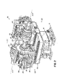
FIG. 1 is a schematic perspective view of a tire building machine in accordance with the present invention under a first condition. -
FIG. 2 is a schematic perspective view of the tire building machine ofFIG. 1 under a second condition. -
FIG. 3 is a schematic top view of the machine ofFIG. 1 . -
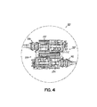
FIG. 4 is a schematic top view of the machine ofFIG. 2 . -
FIG. 5 is a schematic front elevation of an example two drum turret assembly. -
FIG. 6 is a schematic side elevation of the example turret assembly taken alongline 6--6 inFIG. 5 with the drums removed. -
FIG. 7 is a schematic rear elevation of the example turret assembly taken along line 7--7 inFIG. 6 with parts being broken away. -
FIG. 8 is schematic fragmentary top view of the example turret assembly taken along line 8--8 inFIG. 5 . - With reference to
FIGS. 5 ,6, and 7 , anexample base 10 is shown mounted on afloor surface 12 and fastened to aturret support housing 14 bybolts 16 or other suitable fasteners.Pillow blocks 18 may be mounted on thehousing 14 providing bearings for supporting aturret drive shaft 20. Aturret 22 may be mounted on one end of theshaft 20 and may include aturret supporting plate 24. - Referring to
FIGS. 5 and8 , afirst drum 26 may be rotatably mounted on theturret supporting plate 24 and may extend outwardly from afirst side 28 of theturret 22 for rotation about a first horizontal axis A-A in a first position X. Thefirst drum 26 may also be known as a slave drum and may be mounted on aslave shaft 30 rotatably supported in a slave bearing 32 mounted on the supportingplate 24. A slavedrum drive motor 34 may also be mounted on the supportingplate 24 in a driving relationship with theslave shaft 30 through aslave belt 36 extending around pulleys mounted on theslave shaft 30 and the shaft of the slavedrum drive motor 34. - Mounted on a
second side 38 of theturret 22 may be a secondtire building drum 40 rotatable about a second horizontal axis B--B in a second position Y. The secondtire building drum 40, which may be known as a master drum, may be mounted on amaster shaft 42 supported in a master bearing 44 mounted on the supportingplate 24. Themaster shaft 42 may be driven by a masterdrum drive motor 46 mounted on the supportingplate 24 and may be connected by amaster belt 48 to the master shaft through drive pulleys. - As shown in
FIG. 5 , the axis A--A of thefirst drum 26 and the axis B--B of thesecond drum 40 may be in a parallel relationship so that, in an operating position, thefirst drum 26 may have afirst height 50 of 40 inches (101.6 cm) above thefloor surface 12 and thesecond drum 40 may have asecond height 52 of 50 inches (127 cm) above the floor surface. Thus, when manual operations for applying tire components to thedrums drums floor surface 12 in order that the operator may reach the drums. - In addition to the axes A--A and B--B being parallel, the
slave shaft 30 may be vertically offset from themaster shaft 42 for mitigating the horizontal distance thefirst drum 26 andsecond drum 40 extend outwardly/laterally from thefirst side 28 andsecond side 38, respectively. This configuration may limit the space required for rotation of theturret 22 and the depth of apit 54 necessary for permitting rotation of the turret about a horizontal axis C--C of theturret drive shaft 20. - The axes A-A, B--B may be symmetrical about the axis C--C of the
turret drive shaft 20. The master bearing 44 may be mounted on the supportingplate 24 in a predetermined position. Edges of the master bearing 44 may be locatedadjacent registers 55, 56 on the supportingplate 24 with adjustingscrews 57 threaded in the plate. Then, the position of the slave bearing 32 may be adjusted by adjustingscrews 58, 59 threaded on the supportingplate 24 so that the axis A--A of thefirst drum 26 is parallel with the axis B--B of thesecond drum 40, as well as being symmetrical about axis C--C of theturret drive shaft 20. With this adjustment, thefirst drum 26 andsecond drum 40 may be in identical positions for the first position X and the second position Y so that tire components may be applied to the drums in identical positions. - Referring to
FIGS. 6 and 7 , adrive gear 60 may be mounted on a rear end of theturret drive shaft 20. Thedrive gear 60 may have asemi-circular gear rack 61 engagable by apinion gear 62 driven by aturret drive motor 63 mounted on theturret support housing 14. Referring toFIG. 7 , thedrive gear 60 may be rotated from the position shown inFIG. 7 in a clockwise direction 180 degrees so that theturret supporting plate 24, as shown inFIG. 5 will rotate 180 degrees in a counter clockwise direction moving thefirst drum 26 from the first position X shown inFIG. 5 to the second position Y shown inFIG. 5 and moving thesecond drum 40 from the second position Y shown inFIG. 5 to the first position X shown inFIG. 5 . In the two operating positions X and Y, acam roller 64 may be actuated by apneumatic lock 66 extending into atapered slot turret 22 to lock the turret in an operating position. - In the event the
motor 63 does not stop to permit actuation of thecam roller 64 by thepneumatic lock 66, the length of thesemi-circular gear rack 61 may be predetermined for disengaging thepinion 60 whereupon theturret drive shaft 20 may continue to rotate and anarm 72, mounted on the turret drive shaft and extending outwardly therefrom, may be positioned to engageshock absorbers 74 mounted on thehousing 14. One of theshock absorbers 74 may be provided at each side of thehousing 14 to limit the rotation of theturret supporting plate 24 in either direction by engagement with thearm 72. - In an example tire building operation, tire components may be applied to the
first drum 26 and thesecond drum 40 by rotating the drums through actuation of the slavedrum drive motor 34 and masterdrum drive motor 36 in response to suitable controls connected to the motors. After application of the tire components, thecam roller 64 may be released and theturret drive motor 63 actuated in response to suitable controls for rotating theturret 22 through 180 degrees whereby thefirst drum 26 is moved to the second position Y and thesecond drum 40 is moved to the first position X, as shown inFIG. 5 . Simultaneously with the application of additional tire components on thefirst drum 26 in the second position Y at thesecond height 52, tire components may be provided on thesecond tire drum 40 in the first position X, as shown inFIG. 5 . It is understood that thefirst drum 26 andsecond drum 40 may be identical or different sizes and types substituted for these drums and adaptable for different tire building operations. - With reference to
FIGS. 1-4 , amachine 100 in accordance with the present invention may include abase 110 mounted on a floor surface and fastened to aturret support housing 114. Referring toFIGS. 1 and4 , afirst drum 126 is rotatably mounted on aturret support frame 124 and may extend outwardly from afirst side 128 of theturret support frame 124 for rotation about a first horizontal axis A-A. Thefirst drum 126 is mounted on afirst shaft 130 rotatably supported in a first bearing 132 mounted on theturret support frame 124. A first drum drive motor may also be mounted on thesupport frame 124 in a driving relationship with thefirst shaft 130 through a first belt extending around pulleys mounted on thefirst shaft 130 and the shaft of the first drum drive motor. - Mounted on a
second side 138 of the rotatableturret support frame 124 is a secondtire building drum 140 rotatable about a second horizontal axis B--B. The secondtire building drum 140 is mounted on asecond shaft 142 supported in asecond bearing 144 mounted on thesupport frame 124. Thesecond shaft 142 may be driven by a seconddrum drive motor 146 mounted on thesupport frame 124 and may be connected by asecond belt 148 to the second shaft through drive pulleys. - As shown in
FIG. 1 , the axis A--A of thefirst drum 126 and the axis B--B of thesecond drum 140 may be in a parallel relationship so that thefirst drum 126 and thesecond drum 140 may have identical heights above the floor surface (as compared to the example machine ofFIGS. 5-8 ). Thus, when manual operations for applying tire components to thedrums drums - In addition to the axes A--A and B--B being parallel, the
first shaft 130 may be horizontally offset from thesecond shaft 142 for mitigating the horizontal distance thefirst drum 126 andsecond drum 140 extend outwardly/laterally from thefirst side 128 andsecond side 138, respectively. This configuration, by itself, may limit the space required for rotation of thesupport frame 124 about a vertical axis C--C by theturret support housing 114. The axes A--A, B--B may be symmetrical about the vertical axis C--C of theturret support housing 114. - The
machine 100 may further include twocylinders support frame 124. The cylinders may horizontally retract thedrums turret support housing 114 rotates the machine about the axis C--C (FIGS. 2 &4 ). Subsequent to this rotation, thecylinders drums FIGS. 1 &3 ). Thecylinders
Claims (15)
- A tire building machine comprising:a support housing for rotating the machine about a vertical axis;a support frame operatively attached to the support housing such that the support housing rotates the support frame about the vertical axis;a first drum rotatable about a first horizontal axis by a first motor, the first drum and the first motor being secured to the support frame;a first cylinder for horizontally retracting the first drum along the first horizontal axis from an extended position to a retracted position;a second drum rotatable about a second horizontal axis by a second motor, the second horizontal axis being parallel to the first horizontal axis, the second drum and the second motor being secured to the support frame; anda second cylinder for horizontally retracting the second drum along the second horizontal axis from an extended position to a retracted position.
- The tire building machine as set forth in claim 1 wherein the first cylinder extends the first drum from the retracted position to the extended position.
- The tire building machine as set forth in claim 2 wherein the second cylinder extends the second drum from the retracted position to the extended position.
- The tire building machine as set forth in claim 1 wherein the first cylinder and the second cylinder retract the first and second drums simultaneously.
- The tire building machine as set forth in claim 4 wherein the first cylinder and the second cylinder extend the first and second drums simultaneously.
- A method for operating a tire building machine comprising the steps of:operatively attaching a support frame to a support housing such that the support housing rotates the support frame about a vertical axis;securing a first drum and a first motor being to the support frame;rotating the first drum about a first horizontal axis by the first motor;horizontally retracting the first drum along the first horizontal axis from an extended position to a retracted position by a first cylinder;securing a second drum and a second motor being to the support frame;rotating the second drum about a second horizontal axis by the second motor; andhorizontally retracting the second drum along the second horizontal axis from an extended position to a retracted position by a second cylinder.
- The method as set forth in claim 6 further including the step of extending the first cylinder and the first drum from the retracted position to the extended position.
- The method as set forth in claim 6 further including the step of extending the second cylinder and the second drum from the retracted position to the extended position.
- The method as set forth in claim 6 wherein both said retracting steps occur simultaneously.
- The method as set forth in claim 6 further including the step of extending both the first and second drums simultaneously to the extended position.
- A system for rotating a tire building machine comprising:a support housing for rotating the machine about a vertical axis;a support frame operatively attached to the support housing such that the support housing rotates the support frame about the vertical axis;a first drum rotatable about a first horizontal axis, the first drum being secured to the support frame;a first cylinder for horizontally retracting the first drum along the first horizontal axis from an extended position to a retracted position;a second drum rotatable about a second horizontal axis, the second horizontal axis being parallel to the first horizontal axis, the second drum being secured to the support frame; anda second cylinder for horizontally retracting, simultaneously with the first drum, the second drum along the second horizontal axis from an extended position to a retracted position.
- The system as set forth in claim 11 wherein the first cylinder extends the first drum from the retracted position to the extended position.
- The system as set forth in claim 12 wherein the second cylinder extends the second drum from the retracted position to the extended position.
- The system as set forth in claim 13 wherein the first cylinder and the second cylinder retract the first and second drums simultaneously.
- The system as set forth in claim 14 wherein the first cylinder and the second cylinder extend the first and second drums simultaneously.
Applications Claiming Priority (1)
| Application Number | Priority Date | Filing Date | Title |
|---|---|---|---|
| US13/557,252 US20140027063A1 (en) | 2012-07-25 | 2012-07-25 | Tire building machine with extendable drums |
Publications (1)
| Publication Number | Publication Date |
|---|---|
| EP2689921A1 true EP2689921A1 (en) | 2014-01-29 |
Family
ID=48874825
Family Applications (1)
| Application Number | Title | Priority Date | Filing Date |
|---|---|---|---|
| EP13177465.5A Withdrawn EP2689921A1 (en) | 2012-07-25 | 2013-07-22 | Tire building system and method |
Country Status (4)
| Country | Link |
|---|---|
| US (1) | US20140027063A1 (en) |
| EP (1) | EP2689921A1 (en) |
| JP (1) | JP2014024335A (en) |
| CN (1) | CN103568347A (en) |
Families Citing this family (1)
| Publication number | Priority date | Publication date | Assignee | Title |
|---|---|---|---|---|
| CN216506875U (en) * | 2021-12-22 | 2022-05-13 | 软控股份有限公司 | Passenger radial tire forming machine and machine case thereof |
Citations (4)
| Publication number | Priority date | Publication date | Assignee | Title |
|---|---|---|---|---|
| US2028078A (en) * | 1933-02-21 | 1936-01-14 | Wingfoot Corp | Tire building apparatus |
| EP0798104A2 (en) * | 1996-03-26 | 1997-10-01 | The Goodyear Tire & Rubber Company | Two drum turret for tire assembly |
| WO2009131456A1 (en) * | 2008-04-24 | 2009-10-29 | Vmi Holland B.V. | Device for building a tyre |
| US20100024985A1 (en) * | 2008-08-04 | 2010-02-04 | Hiroyuki Onimatsu | Shaping former and system for building green-tire including the same |
Family Cites Families (5)
| Publication number | Priority date | Publication date | Assignee | Title |
|---|---|---|---|---|
| US3802982A (en) * | 1970-01-06 | 1974-04-09 | Steelastic Co | Reinforced tire fabric and method and apparatus for making same |
| GB8411820D0 (en) * | 1984-05-09 | 1984-06-13 | Bates W & A Ltd | Manufacture |
| JPH05154937A (en) * | 1991-12-04 | 1993-06-22 | Bridgestone Corp | Apparatus for forming tire |
| BRPI0419156B1 (en) * | 2004-12-16 | 2015-10-27 | Pirelli | Method and installation for manufacturing vehicle wheel tires |
| JPWO2006137131A1 (en) * | 2005-06-22 | 2009-01-08 | 東洋ゴム工業株式会社 | Tire molding method and rotational movement device for drum movement support base in tire molding process |
-
2012
- 2012-07-25 US US13/557,252 patent/US20140027063A1/en not_active Abandoned
-
2013
- 2013-07-22 EP EP13177465.5A patent/EP2689921A1/en not_active Withdrawn
- 2013-07-25 CN CN201310315352.1A patent/CN103568347A/en active Pending
- 2013-07-25 JP JP2013154529A patent/JP2014024335A/en active Pending
Patent Citations (4)
| Publication number | Priority date | Publication date | Assignee | Title |
|---|---|---|---|---|
| US2028078A (en) * | 1933-02-21 | 1936-01-14 | Wingfoot Corp | Tire building apparatus |
| EP0798104A2 (en) * | 1996-03-26 | 1997-10-01 | The Goodyear Tire & Rubber Company | Two drum turret for tire assembly |
| WO2009131456A1 (en) * | 2008-04-24 | 2009-10-29 | Vmi Holland B.V. | Device for building a tyre |
| US20100024985A1 (en) * | 2008-08-04 | 2010-02-04 | Hiroyuki Onimatsu | Shaping former and system for building green-tire including the same |
Also Published As
| Publication number | Publication date |
|---|---|
| CN103568347A (en) | 2014-02-12 |
| US20140027063A1 (en) | 2014-01-30 |
| JP2014024335A (en) | 2014-02-06 |
Similar Documents
| Publication | Publication Date | Title |
|---|---|---|
| EP3406465B1 (en) | Tyre dismounting apparatus adapted to be installed on a motor vehicle and tyre dismounting method | |
| CN202450813U (en) | Two-layer lifting and rotating moving simple parking device | |
| CN113245927B (en) | An automatic loading and unloading device for a centerless grinder used for cross shaft processing | |
| EP0798104B1 (en) | Two drum turret for tire assembly | |
| US20140027063A1 (en) | Tire building machine with extendable drums | |
| CA2565458A1 (en) | A method and apparatus for operating a vehicle on rails of a railroad track with an auxiliary drive assembly | |
| EP2835253A2 (en) | Component applying/cutting apparatus for a tire building machine and method for applying a component on a tire building machine | |
| CN109702067A (en) | A kind of pipe fitting spinning method and spinning machine with improved structure | |
| CN219535409U (en) | Auxiliary device for installation of power distribution cabinet | |
| CN107470916A (en) | Steel plate transverse shearing production line and apply its horizontal shearing process of steel plate | |
| CN216082047U (en) | Automobile brake loading type brake detection table | |
| CN116692472A (en) | Clamping device for front cover of automobile | |
| CN204076032U (en) | A kind of reel shot-blasting machine | |
| CN221563117U (en) | Auxiliary installation device for assembling and disassembling aircraft wheel with tire | |
| CN2188045Y (en) | Tyre dismounting machine | |
| CN222386732U (en) | A clamping device for pulley processing | |
| CN215332695U (en) | Rotation type drilling pile integrative frame | |
| CN206393583U (en) | A kind of movable rotary platform for being exclusively used in automobile engine numerical control packer | |
| CN111825016A (en) | Device for moving an object and a movable vehicle | |
| CN224145693U (en) | Adjustable clamp for dismounting tire | |
| CN217226186U (en) | Slotting device for electric power construction | |
| CN218593177U (en) | Cutting device for tire processing | |
| CN220583675U (en) | Automobile wheel balance weight pulling-out force detection device | |
| CN211730208U (en) | Tubular workpiece machining and shaping equipment | |
| CN222448468U (en) | A hardware processing and cutting equipment |
Legal Events
| Date | Code | Title | Description |
|---|---|---|---|
| PUAI | Public reference made under article 153(3) epc to a published international application that has entered the european phase |
Free format text: ORIGINAL CODE: 0009012 |
|
| AK | Designated contracting states |
Kind code of ref document: A1 Designated state(s): AL AT BE BG CH CY CZ DE DK EE ES FI FR GB GR HR HU IE IS IT LI LT LU LV MC MK MT NL NO PL PT RO RS SE SI SK SM TR |
|
| AX | Request for extension of the european patent |
Extension state: BA ME |
|
| 17P | Request for examination filed |
Effective date: 20140729 |
|
| RBV | Designated contracting states (corrected) |
Designated state(s): AL AT BE BG CH CY CZ DE DK EE ES FI FR GB GR HR HU IE IS IT LI LT LU LV MC MK MT NL NO PL PT RO RS SE SI SK SM TR |
|
| 17Q | First examination report despatched |
Effective date: 20150813 |
|
| STAA | Information on the status of an ep patent application or granted ep patent |
Free format text: STATUS: THE APPLICATION IS DEEMED TO BE WITHDRAWN |
|
| 18D | Application deemed to be withdrawn |
Effective date: 20161115 |