EP2689262B1 - Unwrapping von phasenbildern in der magnetresonanzbildgebung - Google Patents
Unwrapping von phasenbildern in der magnetresonanzbildgebung Download PDFInfo
- Publication number
- EP2689262B1 EP2689262B1 EP12703423.9A EP12703423A EP2689262B1 EP 2689262 B1 EP2689262 B1 EP 2689262B1 EP 12703423 A EP12703423 A EP 12703423A EP 2689262 B1 EP2689262 B1 EP 2689262B1
- Authority
- EP
- European Patent Office
- Prior art keywords
- image
- phase
- difference
- images
- offset
- Prior art date
- Legal status (The legal status is an assumption and is not a legal conclusion. Google has not performed a legal analysis and makes no representation as to the accuracy of the status listed.)
- Not-in-force
Links
- 238000002595 magnetic resonance imaging Methods 0.000 title claims description 14
- 238000000034 method Methods 0.000 claims description 42
- 238000012937 correction Methods 0.000 claims description 29
- 230000001668 ameliorated effect Effects 0.000 claims description 27
- 230000005284 excitation Effects 0.000 claims description 12
- 230000005291 magnetic effect Effects 0.000 description 18
- 210000001519 tissue Anatomy 0.000 description 10
- XEEYBQQBJWHFJM-UHFFFAOYSA-N Iron Chemical compound [Fe] XEEYBQQBJWHFJM-UHFFFAOYSA-N 0.000 description 6
- 230000003068 static effect Effects 0.000 description 6
- 238000003384 imaging method Methods 0.000 description 4
- 230000002123 temporal effect Effects 0.000 description 4
- 229910052742 iron Inorganic materials 0.000 description 3
- 238000004458 analytical method Methods 0.000 description 2
- 230000000694 effects Effects 0.000 description 2
- 230000005855 radiation Effects 0.000 description 2
- 210000003462 vein Anatomy 0.000 description 2
- INGWEZCOABYORO-UHFFFAOYSA-N 2-(furan-2-yl)-7-methyl-1h-1,8-naphthyridin-4-one Chemical compound N=1C2=NC(C)=CC=C2C(O)=CC=1C1=CC=CO1 INGWEZCOABYORO-UHFFFAOYSA-N 0.000 description 1
- 238000013459 approach Methods 0.000 description 1
- 108010002255 deoxyhemoglobin Proteins 0.000 description 1
- 230000006866 deterioration Effects 0.000 description 1
- 238000002059 diagnostic imaging Methods 0.000 description 1
- 238000010586 diagram Methods 0.000 description 1
- 238000002592 echocardiography Methods 0.000 description 1
- 230000005670 electromagnetic radiation Effects 0.000 description 1
- 238000000605 extraction Methods 0.000 description 1
- 210000004884 grey matter Anatomy 0.000 description 1
- 238000001727 in vivo Methods 0.000 description 1
- 238000013507 mapping Methods 0.000 description 1
- 239000000463 material Substances 0.000 description 1
- 238000005259 measurement Methods 0.000 description 1
- 238000012986 modification Methods 0.000 description 1
- 230000004048 modification Effects 0.000 description 1
- 230000005298 paramagnetic effect Effects 0.000 description 1
- 230000035945 sensitivity Effects 0.000 description 1
- 210000004872 soft tissue Anatomy 0.000 description 1
- 238000012800 visualization Methods 0.000 description 1
- XLYOFNOQVPJJNP-UHFFFAOYSA-N water Substances O XLYOFNOQVPJJNP-UHFFFAOYSA-N 0.000 description 1
- 210000004885 white matter Anatomy 0.000 description 1
Images




Classifications
-
- G—PHYSICS
- G01—MEASURING; TESTING
- G01R—MEASURING ELECTRIC VARIABLES; MEASURING MAGNETIC VARIABLES
- G01R33/00—Arrangements or instruments for measuring magnetic variables
- G01R33/20—Arrangements or instruments for measuring magnetic variables involving magnetic resonance
- G01R33/44—Arrangements or instruments for measuring magnetic variables involving magnetic resonance using nuclear magnetic resonance [NMR]
- G01R33/48—NMR imaging systems
- G01R33/54—Signal processing systems, e.g. using pulse sequences ; Generation or control of pulse sequences; Operator console
- G01R33/56—Image enhancement or correction, e.g. subtraction or averaging techniques, e.g. improvement of signal-to-noise ratio and resolution
- G01R33/565—Correction of image distortions, e.g. due to magnetic field inhomogeneities
-
- G—PHYSICS
- G01—MEASURING; TESTING
- G01R—MEASURING ELECTRIC VARIABLES; MEASURING MAGNETIC VARIABLES
- G01R33/00—Arrangements or instruments for measuring magnetic variables
- G01R33/20—Arrangements or instruments for measuring magnetic variables involving magnetic resonance
- G01R33/44—Arrangements or instruments for measuring magnetic variables involving magnetic resonance using nuclear magnetic resonance [NMR]
- G01R33/48—NMR imaging systems
- G01R33/54—Signal processing systems, e.g. using pulse sequences ; Generation or control of pulse sequences; Operator console
- G01R33/56—Image enhancement or correction, e.g. subtraction or averaging techniques, e.g. improvement of signal-to-noise ratio and resolution
- G01R33/565—Correction of image distortions, e.g. due to magnetic field inhomogeneities
- G01R33/56536—Correction of image distortions, e.g. due to magnetic field inhomogeneities due to magnetic susceptibility variations
-
- G—PHYSICS
- G01—MEASURING; TESTING
- G01R—MEASURING ELECTRIC VARIABLES; MEASURING MAGNETIC VARIABLES
- G01R33/00—Arrangements or instruments for measuring magnetic variables
- G01R33/20—Arrangements or instruments for measuring magnetic variables involving magnetic resonance
- G01R33/44—Arrangements or instruments for measuring magnetic variables involving magnetic resonance using nuclear magnetic resonance [NMR]
- G01R33/48—NMR imaging systems
- G01R33/54—Signal processing systems, e.g. using pulse sequences ; Generation or control of pulse sequences; Operator console
- G01R33/56—Image enhancement or correction, e.g. subtraction or averaging techniques, e.g. improvement of signal-to-noise ratio and resolution
- G01R33/565—Correction of image distortions, e.g. due to magnetic field inhomogeneities
- G01R33/56563—Correction of image distortions, e.g. due to magnetic field inhomogeneities caused by a distortion of the main magnetic field B0, e.g. temporal variation of the magnitude or spatial inhomogeneity of B0
Definitions
- the present invention relates to a method of unwrapping a phase image in Magnetic Resonance Imaging (MRI).
- MRI Magnetic Resonance Imaging
- MRI is used in radiology to visualize details of structures in a patient's body.
- the patient is placed inside a powerful static magnetic field.
- an electro-magnetic radio-frequency pulse the nuclei resonating at this frequency deflect and then gradually relax towards the static field while emitting detectable magnetic radiation, which can be captured as an "echo” at a certain time after excitation ("echo time”).
- Relaxation times and resonance frequency of the nuclei depend both on local properties of the tissue material, which represents the underlying principle allowing visualization of these properties, and the magnetic field strength.
- voxels By superposing lateral and longitudinal gradient fields and adjusting the excitation frequency, certain volumetric regions (“voxels”) can be measured by both selective excitation and frequency analysis of the captured echo signals. Fourier-transforming the latter generates complex representations of the frequency values and their phases, which can be made readable.
- the excitation When the excitation is performed on two-dimensional slices, they are selected by adjusting the gradients in the magnetic field strength, thereafter resonant frequency values are captured and processed, forming 2D-images multiple of which can be merged to form a 3D-representation. Most procedures in MRI are therefore executed on pixels of 2D-images.
- 3D imaging a thick volume of tissue is excited instead of a thin section, and slice encoding is replaced by an additional gradient loop in the slice direction.
- phase values allow for the extraction of additional information about local properties inside the tissue. Specifically in MRI at higher magnetic field strengths, which promise better images, this additional information would be useful to support the enhancement of image quality. Therefore applications using the phase information of complex MR-images become increasingly important.
- phase images suffer from a conceptual ambiguity: As adding 2n to a phase value results in the same phase, the encoding range in captured phase values is effectively limited to 2n radians. Variations in phase of an object when passing through 2n lead to discontinuities in the image known as "phase wraps", which distort the readability and obscure interesting phase features.
- phase wraps A number of methods has been developed for removing phase wraps, which can broadly be categorised as spatial or as temporal unwrapping methods. Spatial unwrapping methods use phase changes of more than n between spatially adjacent voxels as identifiers for a wrap in a region-growing approach. These methods only require one phase image but are computationally complex and prone to error specifically at regions of higher phase variation (e.g. close to veins).
- Temporal unwrapping methods which analyse phase evolution over time for each voxel - or pixel - separately, are more robust and computationally simpler. They are based on exploiting the difference in two or more phase images acquired at different echo times, e.g. us 2009/0256567 A1 or Funai A. K. et al, "Regularized Field Map Estimation in MRI", IEEE Transactions on Medical Imaging, IEEE USA, vol. 27, no. 10, October 2008, pages 1484 - 1494 . If the spacing between these echo times is sufficiently small, wrap-free phase difference images are obtained.
- Multi-echo images are limited in the minimum echo time spacing, as the acquisition of each echo takes a finite amount of time. This time is determined by the acquisition rate (which in turn determines the SNR) and the number of samples, and is typically around 5 ms for a high SNR, high resolution image.
- an echo time spacing of this size is too long to reliably avoid phase wraps in phase difference images, where echo time spacings of around 0.1 - 2 ms would be necessary, depending on local field deviations.
- a second possibility is to use repeated single-echo acquisitions with slightly different echo times. In this way the echo time spacing can be chosen to be arbitrarily low.
- this method suffers from a substantially extended measurement time, as a complete excitation cycle has to be executed for each echo acquisition.
- acquiring three echo images with repeated single-echo acquisition takes roughly three times as long as in multi-echo acquisition.
- errors are likely to occur due to interim changes in the tissue (e.g. patient motion) between the individual image acquisitions.
- temporal unwrapping methods do not yield unwrapped phase images but rather unwrapped phase difference images.
- Wrap-free phase difference images have much lower contrast between grey and white matter than unwrapped phase images.
- this object is met by a method of unwrapping a phase image in magnetic resonance imaging, comprising acquiring three phase images at three different echo times following a single excitation with unequal echo time spacings therebetween, calculating a first difference image between the first two and a second difference image between the last two of said three phase images and calculating a third difference image between the first and the second difference images, generating a phase correction map from said third difference image, and adding said phase correction map to one of said phase images acquired.
- the method of the invention allows for a temporal unwrapping of phase images which can be performed quickly.
- a third difference image as a "difference-of-differences image"
- the relevant time base of which is determined solely by the difference in the echo time spacings of the first and the second and the second and the third acquisition images, respectively.
- This difference in echo time spacings can be chosen - with the only limitation of signal-to-noise ratio (SNR) considerations - as small as possible and thus phase wraps in the third difference image can be avoided over a broad range of signal phases in the object to be investigated, even though their phase value representations per se are limited to 2n.
- Applying information from this third difference image via a phase correction map to one of the original phase images yields an unwrapped phase image rather than only phase difference images, and avoids the loss of contrast as a consequence.
- Unwrapped phase images obtained with the method of the invention have both better contrast and higher SNR.
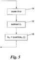
- the step of generating the phase correction map comprises scaling said third difference image by a scaling factor, subtracting said scaled third difference image from the phase image to unwrap, and quantizing the result of said subtraction in steps of 2n, to obtain the phase correction map.
- the invention provides for a quantized phase correction map, which is individual for each phase image to unwrap, contains only multiple values of 2n and can be generated with low computational complexity.
- the phase correction map can be directly applied to unwrap the phase image by adding on a pixel-by-pixel basis.
- said scaling factor is formed by dividing the echo time of the phase image to unwrap by the difference between said echo time spacings.
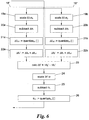
- the step of generating the phase correction map comprises scaling said third difference image by a first scaling factor formed by dividing the first echo time spacing by the difference between said echo time spacings, subtracting this scaled third difference image and the first difference image from each other, quantizing the result in steps of 2n, and adding the quantized result to the first difference image, to obtain an ameliorated first difference image; scaling said third difference image by a second scaling factor formed by dividing the second echo time spacing by the difference between said echo time spacings, subtracting this scaled third difference image and the second difference image from each other, quantizing the result in steps of 2 ⁇ , and adding the quantized result to the second difference image, to obtain an ameliorated second difference image; calculating an ameliorated third difference image between the ameliorated first and second difference images; scaling
- the steps of ameliorating both the first and second difference images extends their range of phase difference values.
- it will be enhanced in terms of its SNR.
- the enhanced SNR of the ameliorated third difference image increases the precision in the subsequent steps of unwrapping.
- MRI is used in radiology to visualize soft tissues, non-invasively and in vivo.
- the process of generating an image of a patient usually consists of the following steps: creating a bulk (longitudinal) magnetisation in the tissue by placing the patient inside a powerful static magnetic field; creating regional variation in this magnetic field, and thereby in the resonant frequency of the nuclei, with three comparatively small, linear perpendicular magnetic fields ("gradients"); disturbing the magnetisation with pulses of radio-frequency (RF) electromagnetic radiation applied at the resonant frequency, tipping the magnetisation into the transverse plane (which is perpendicular to the static magnetic field); and acquiring the RF signals emitted by the tissues as the magnetisation relaxes to the longitudinal direction.
- RF radio-frequency
- spacing encoding of the signal works as follows.
- the first gradient field (“slice select”) is applied during RF excitation, so that only spins in a narrow section of tissue are excited.
- the second (“readout”) is applied while the signal is being acquired, so that spins along the readout axis are encoded by their resonant frequency.
- a number of such excitation-readout steps are acquired with differing applications of the third (“phase-encode”) gradient, which encodes the signal along that gradient direction according to dephasing rate.
- slice encoding is replaced by a second loop of phase-encoding steps in the slice gradient direction.
- the RF signals emitted by the patient are captured as "echoes" at a certain time after excitation by multiple receiver coils.
- Fourier-transforming the acquired MR signals generates images of the patient, which consist of a large number of voxels, i.e. pixels in the 2D-slices, reflecting the local proton density and magnetic properties of the tissue.
- the acquired MR signals are complex valued. Images of the patient, as the Fourier-transform of the acquired signal, are therefore likewise complex valued, that is, image signals consist of a magnitude and a phase and can be represented in conventional complex number notation.
- phase contains additional information, which can be clinically useful. While the magnitude of the signal decays exponentially with echo time, phase evolves linearly, and reflects local deviation from the main magnetic field strength. For this reason, two or more phase images acquired at different echo times can be used to map the local magnetic field ("field mapping").
- field mapping The sensitivity of phase to local magnetic field also allows local iron (which is highly paramagnetic) to be imaged.
- Phase can be used, in combination with magnitude, to depict veins, due to the iron content of the deoxyhemoglobin iron, in a technique known as Susceptibility-Weighted Imaging. These techniques benefit from high static magnetic field, which provides enhanced magnetic susceptibility effects and higher quality images due to increased SNR.
- Fig. 1 As shown in Fig. 1 , captured signals of an acquired two-dimensional MR-image 1 of an object to be investigated cannot be interpreted straightforwardly.
- 2D-Fourier-transforming image 1 results in a complex image 2 which can be separated on a pixel-by-pixel basis into a magnitude image 3 and a phase image 4.
- the phase image 4 typically shows phase wraps 5 because of the limitation in the encoding range to 2n discussed at the outset.
- Figs. 2 to 4 show a first embodiment of a method to remove (“unwrap") such phase wraps 5 from a phase image 4.
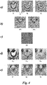
- a first step 6 of the method of unwrapping three MR-images are acquired at three different echo times TE 1 , TE 2 and TE 3 following a single excitation pulse 7 as shown in Fig. 3 ; step 6 leads to three phase images ⁇ 1 , ⁇ 2 , ⁇ 3 examples of which are depicted in Fig. 4a .
- the phase images ⁇ 1 , ⁇ 2 , ⁇ 3 typically show phase wraps 5.
- the acquisition of each of the phase images ⁇ 1 , ⁇ 2 , ⁇ 3 at the three different echo times TE 1 , TE 2 , TE 3 takes a certain, finite acquisition period 8, 9, 10.
- the echo times TE 1 , TE 2 , TE 3 are preferably also chosen in such a way that the acquisition periods 8, 9 and 10 do not overlap.
- the echo time spacing ⁇ TE 12 can be greater or less than the echo time spacing ⁇ TE 23 . It is also possible to acquire more than three phase images ⁇ 1 , ⁇ 2 , ⁇ 3 at more than three echo times TE 1 , TE 2 , TE 3 and choose three of them for the further unwrapping.
- Fig. 4b shows examples of phase difference images ⁇ 1 and ⁇ 2 deriving from calculation step 11.
- An example of the third difference image ⁇ is illustrated in Fig. 4c .
- the difference ⁇ TE in echo time spacings ⁇ TE 12 , ⁇ TE 23 is chosen to be less than the time it takes for the phase to change by 2n in the pixels to unwrap, which time is determined by the local deviation from the static magnetic field, to avoid phase wraps in the third difference image ⁇ as best as possible.
- a phase correction map ⁇ n1 is generated on the basis of the third difference image ⁇ for unwrapping the first phase image ⁇ 1 . While the following description of the method deals with unwrapping the first phase image ⁇ 1 , it should be noted that any other phase image ⁇ 2 , ⁇ 3 could be unwrapped with respective phase correction maps ⁇ n2 , ⁇ n3 calculated accordingly, see Fig. 4d .
- Fig. 5 shows a first variant of generating the phase correction map ⁇ n1 in detail.
- the operator ⁇ in the present disclosure shall denote the function of rounding to the nearest integer.
- phase correction map ⁇ n1 is added pixel-by-pixel to the phase image ⁇ 1 to obtain an unwrapped phase image ⁇ 1 '.
- the unwrapped phase image ⁇ 1 ' is shown in Fig. 4e , together with further unwrapped phase images ⁇ 2, and ⁇ 3 ' calculated accordingly for the phase images ⁇ 2 and ⁇ 3 , respectively.
- Fig. 6 shows an alternative to Fig. 5 for generating the phase correction map ⁇ n1 in step 13.
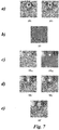
- each of the first and second difference images ⁇ 1 , ⁇ 2 ( Fig. 7a ) is ameliorated by unwrapping it in a separate branch 18', 18" using the third difference image ⁇ ( Fig. 7b ) much in the same way as in steps 14 to 16 of the above embodiment.
- the third difference ⁇ image is re-calculated on the basis of such ameliorated first and second difference images ⁇ 1 ', ⁇ 2 ' to obtain an ameliorated third difference image ⁇ ' with enhanced SNR, providing an alternative basis for generating the phase correction map ⁇ n1 .
- ⁇ 1 TE 2 ⁇ TE 1 ⁇ TE
- Figs. 8 and 9 show an optional addition to the methods of Figs. 2 to 7 for removing wraps due to receiver offsets.
- a first step 27 at least two unwrapped phase images ⁇ 1 ', ⁇ 2 ' ( Fig. 9a ) are obtained from the three acquired phase images ⁇ 1 , ⁇ 2 , ⁇ 3 according to one of the methods detailed above.
- any other combination of two unwrapped phase images ⁇ 1 ', ⁇ 2 ', ⁇ 3 ' could be used together with the respective echo times TE 1 , TE 2 , TE 3 to calculate the receiver offset image ⁇ rx .
- step 29 the receiver offset image ⁇ rx is subtracted from the unwrapped phase image ⁇ 1 ', ⁇ 2 ', ⁇ 3 ' to be offset-compensated, here ⁇ 1' , to obtain a modified offset image ⁇ rx1 an example of which can be seen in Fig. 9c .
Landscapes
- Physics & Mathematics (AREA)
- Health & Medical Sciences (AREA)
- General Health & Medical Sciences (AREA)
- Nuclear Medicine, Radiotherapy & Molecular Imaging (AREA)
- Radiology & Medical Imaging (AREA)
- Engineering & Computer Science (AREA)
- Signal Processing (AREA)
- High Energy & Nuclear Physics (AREA)
- Condensed Matter Physics & Semiconductors (AREA)
- General Physics & Mathematics (AREA)
- Magnetic Resonance Imaging Apparatus (AREA)
Claims (6)
- Verfahren zum Entfalten eines Phasenbilds (θ1) in der Magnetresonanz-Bildgebung, umfassend
Erfassen von drei Phasenbildern (θ1, θ2, θ3) zu drei verschiedenen Echozeiten (TE1, TE2, TE3) nach einer einzigen Anregung mit ungleichen Echozeitabständen (ΔTE12, ΔTE23) dazwischen,
Berechnen eines ersten Differenzbilds (Δθ1) zwischen den ersten beiden und eines zweiten Differenzbilds (Δθ2) zwischen den letzten beiden der genannten drei Phasenbildern (θ1, θ2, θ3) und Berechnen eines dritten Differenzbilds (δθ) zwischen dem ersten und dem zweiten Differenzbild (Δθ1, Δθ2) ;
Erzeugen einer Phasenkorrekturkarte (θn1) basierend auf zumindest dem genannten dritten Differenzbild (δθ) und dem zu entfaltenden Phasenbild (θ1), und
Hinzufügen der genannten Phasenkorrekturkarte (θn1) zu dem zu entfaltenden Phasenbild (θ1) der erfassten Phasenbilder (θ1, θ2, θ3), - Verfahren nach Anspruch 1, wobei der Schritt des Erzeugens der Phasenkorrekturkarte (θn1) umfasst
Skalieren des genannten dritten Differenzbilds (δθ) um einen Skalierfaktor (σ),
Subtrahieren des genannten skalierten dritten Differenzbilds von dem zu entfaltenden Phasenbild (θ1), und
Quantisieren des Ergebnisses der genannten Subtraktion in Schritten von 2n, um die Phasenkorrekturkarte (θn1) zu erhalten. - Verfahren nach Anspruch 2, wobei der genannte Skalierfaktor (σ) durch Dividieren der Echozeit (TE1) des zu entfaltenden Phasenbilds (θ1) durch die Differenz (δTE) zwischen den genannten Echozeitabständen (ΔTE12, ΔTE23) gebildet wird.
- Verfahren nach Anspruch 1, wobei der Schritt des Erzeugens der Phasenkorrekturkarte (θn1) umfasst
Skalieren des genannten dritten Phasenbilds (δθ) um einen ersten Skalierfaktor (σ1), der durch Dividieren des ersten Echozeitabstands (ΔTE12) durch die Differenz (δTE) zwischen den genannten Echozeitabständen (ΔTE12, ΔTE23) gebildet wird, Subtrahieren dieses skalierten dritten Differenzbilds von dem ersten Differenzbild (Δθ1), Quantisieren des Ergebnisses in Schritten von 2n, und Addieren des quantisierten Ergebnisses zu dem ersten Differenzbild (Δθ1), um ein verbessertes erstes Differenzbild (Δθ1') zu erhalten;
Skalieren des genannten dritten Phasenbilds (δθ) um einen zweiten Skalierfaktor (σ2), der durch Dividieren des zweiten Echozeitabstands (ΔTE12) durch die Differenz (δTE) zwischen den genannten Echozeitabständen (ΔTE12, ΔTE23) gebildet wird, Subtrahieren dieses skalierten dritten Differenzbilds von dem zweiten Differenzbild (Δθ2), Quantisieren des Ergebnisses in Schritten von 2n, und Addieren des quantisierten Ergebnisses zu dem zweiten Differenzbild (Δθ2), um ein verbessertes zweites Differenzbild (Δθ2') zu erhalten;
Berechnen eines verbesserten dritten Differenzbilds (δθ') zwischen dem verbesserten ersten und dem verbesserten zweiten Differenzbild (Δθ1', Δθ2');
Skalieren des genannten verbesserten dritten Differenzbilds um den genannten Skalierfaktor (σ);
Subtrahieren des genannten skalierten verbesserten dritten Differenzbilds von dem zu entfaltenden Phasenbild (θ1) ; und
Quantisieren des Ergebnisses der genannten Subtraktion in Schritten von 2n, um die Phasenkorrekturkarte (θn1) zu erhalten. - Verfahren zum Entfalten und Offset-Kompensieren eines Phasenbilds (θ1) in der Magnetresonanz-Bildgebung, umfassend:Entfalten eines ersten und eines zweiten Phasenbilds (θ1, θ2), jeweils gemäß dem Verfahren nach einem der Ansprüche 1 bis 3;Berechnen eines Offsetbilds (θrx) aus dem genannten ersten und dem genannten zweiten entfalteten Phasenbild (θ1', θ2') gemäß
 θ rx das genannte Offsetbild ist,θ 1 ' das genannte erste entfaltete Phasenbild ist, θ 2 ' das genannte zweite entfaltete Phasenbild ist,TE1 die genannte erste Echozeit ist, undTE2 die genannte zweite Echozeit ist;Subtrahieren des Offsetbilds (θrx) von einem entfalteten Phasenbild (θ1'), das offsetkompensiert werden soll, um ein modifiziertes Offsetbild (θrx1) zu erhalten;Skalieren des genannten dritten Differenzbilds (δθ) um den genannten Skalierfaktor (σ);Subtrahieren des genannten skalierten Ergebnisses von dem genannten modifizierten Offsetbild (θrx1);Quantisieren des Subtraktionsergebnisses in Schritten von 2n; undAddieren des quantisierten Ergebnisses zu dem genannten modifizierten Offsetbild (θrx1).
 - Verfahren zum Entfalten und Offset-Kompensieren eines Phasenbilds (θ1) in der Magnetresonanz-Bildgebung, umfassend:Entfalten eines ersten und eines zweiten Phasenbilds (θ1, θ2), jeweils gemäß dem Verfahren nach Anspruch 4;Berechnen eines Offsetbilds (θrx) aus dem genannten ersten und dem genannten zweiten entfalteten Phasenbild (θ1', θ2') gemäß
 θ rx das genannte Offsetbild ist,θ 1 ' das genannte erste entfaltete Phasenbild ist, θ 2 ' das genannte zweite entfaltete Phasenbild ist,TE1 die genannte erste Echozeit ist, undTE2 die genannte zweite Echozeit ist;Subtrahieren des Offsetbilds (θrx) von einem entfalteten Phasenbild (θ1'), das offsetkompensiert werden soll, um ein modifiziertes Offsetbild (θrx1) zu erhalten;Skalieren des genannten verbesserten dritten Differenzbilds (δθ') um den genannten Skalierfaktor (σ);Subtrahieren des genannten skalierten Ergebnisses von dem genannten modifizierten Offsetbild (θrx1);Quantisieren des Subtraktionsergebnisses in Schritten von 2n; undAddieren des quantisierten Ergebnisses zu dem genannten modifizierten Offsetbild (θrx1).
Priority Applications (1)
| Application Number | Priority Date | Filing Date | Title |
|---|---|---|---|
| EP12703423.9A EP2689262B9 (de) | 2011-03-25 | 2012-01-05 | Unwrapping von phasenbildern in der magnetresonanzbildgebung |
Applications Claiming Priority (3)
| Application Number | Priority Date | Filing Date | Title |
|---|---|---|---|
| EP11450043A EP2503350A1 (de) | 2011-03-25 | 2011-03-25 | Entfaltung von Phasenbildern in der Magnetresonanzbildgebung |
| PCT/AT2012/050002 WO2012129585A1 (en) | 2011-03-25 | 2012-01-05 | Unwrapping phase images in magnetic resonance imaging |
| EP12703423.9A EP2689262B9 (de) | 2011-03-25 | 2012-01-05 | Unwrapping von phasenbildern in der magnetresonanzbildgebung |
Publications (3)
| Publication Number | Publication Date |
|---|---|
| EP2689262A1 EP2689262A1 (de) | 2014-01-29 |
| EP2689262B1 true EP2689262B1 (de) | 2016-04-13 |
| EP2689262B9 EP2689262B9 (de) | 2016-06-08 |
Family
ID=44474951
Family Applications (2)
| Application Number | Title | Priority Date | Filing Date |
|---|---|---|---|
| EP11450043A Withdrawn EP2503350A1 (de) | 2011-03-25 | 2011-03-25 | Entfaltung von Phasenbildern in der Magnetresonanzbildgebung |
| EP12703423.9A Not-in-force EP2689262B9 (de) | 2011-03-25 | 2012-01-05 | Unwrapping von phasenbildern in der magnetresonanzbildgebung |
Family Applications Before (1)
| Application Number | Title | Priority Date | Filing Date |
|---|---|---|---|
| EP11450043A Withdrawn EP2503350A1 (de) | 2011-03-25 | 2011-03-25 | Entfaltung von Phasenbildern in der Magnetresonanzbildgebung |
Country Status (2)
| Country | Link |
|---|---|
| EP (2) | EP2503350A1 (de) |
| WO (1) | WO2012129585A1 (de) |
Families Citing this family (7)
| Publication number | Priority date | Publication date | Assignee | Title |
|---|---|---|---|---|
| US10067211B2 (en) | 2012-12-10 | 2018-09-04 | The General Hospital Corporation | System and method for estimating phase measurements in magnetic resonance imaging |
| DE102012223789B4 (de) * | 2012-12-19 | 2014-07-17 | Siemens Aktiengesellschaft | Ermittlung einer Phasendifferenz-Karte |
| GB201301795D0 (en) | 2013-02-01 | 2013-03-20 | Ucl Business Plc | Apparatus and method for correcting susceptibility artefacts in a magnetic resonance image |
| DE102013213592B4 (de) | 2013-07-11 | 2016-06-09 | Siemens Healthcare Gmbh | Verfahren zur Ermittlung einer B1-Phasenkarte und Magnetresonanzeinrichtung |
| US10145925B2 (en) | 2014-05-08 | 2018-12-04 | The Arizona Board Of Regents On Behalf Of The University Of Arizona | MRI with reconstruction of MR phase image |
| KR101725681B1 (ko) * | 2015-06-30 | 2017-04-11 | 연세대학교 산학협력단 | 자기 공명 영상 장치에서 위상 펼침 방법 및 그 방법을 사용하는 자기 공명 영상 장치 |
| CN114754890B (zh) * | 2021-02-08 | 2025-05-13 | 华科精准(北京)医疗设备股份有限公司 | 一种磁共振温度成像方法与系统 |
Family Cites Families (1)
| Publication number | Priority date | Publication date | Assignee | Title |
|---|---|---|---|---|
| US8085041B2 (en) * | 2008-04-10 | 2011-12-27 | General Electric Company | Three-point method and system for fast and robust field mapping for EPI geometric distortion correction |
-
2011
- 2011-03-25 EP EP11450043A patent/EP2503350A1/de not_active Withdrawn
-
2012
- 2012-01-05 EP EP12703423.9A patent/EP2689262B9/de not_active Not-in-force
- 2012-01-05 WO PCT/AT2012/050002 patent/WO2012129585A1/en not_active Ceased
Also Published As
| Publication number | Publication date |
|---|---|
| EP2689262A1 (de) | 2014-01-29 |
| EP2503350A9 (de) | 2012-11-14 |
| EP2689262B9 (de) | 2016-06-08 |
| EP2503350A1 (de) | 2012-09-26 |
| WO2012129585A1 (en) | 2012-10-04 |
Similar Documents
| Publication | Publication Date | Title |
|---|---|---|
| RU2605524C2 (ru) | Магнитно-резонансная визуализация с подавлением артефактов потока | |
| US7710115B2 (en) | Independent phase modulation for efficient dual-band 3D imaging | |
| JP6220331B2 (ja) | 脂肪抑制のために化学シフト・エンコードを用いるコントラスト増強磁気共鳴血管造影法 | |
| EP2689262B9 (de) | Unwrapping von phasenbildern in der magnetresonanzbildgebung | |
| CN105143906B (zh) | 金属抗mr成像 | |
| US8030921B2 (en) | Methods for fat signal suppression in magnetic resonance imaging | |
| JP5848713B2 (ja) | 磁気共鳴イメージング装置及びコントラスト強調画像取得方法 | |
| WO2013150407A1 (en) | Mr imaging using apt contrast enhancement and sampling at multiple echo times | |
| CN108778116A (zh) | 磁共振成像装置以及图像处理方法 | |
| JP2004121466A (ja) | 磁気共鳴撮影装置 | |
| EP2495579B1 (de) | Verfahren zur Erzeugung von 2D- oder 3D-Karten von T1 und T2-Relaxationszeiten in der Magnetresonanzbildgebung | |
| CN105934683A (zh) | 具有对主磁场变化的估计的dixon型水/脂肪分离的mri | |
| US9535148B2 (en) | Dynamic contrast enhanced magnetic resonance imaging with high spatial-temporal resolution | |
| Schmidt et al. | High-resolution quantitative T2 mapping of the human brain at 7 T using a multi-echo spin-echo sequence and dictionary-based modeling | |
| JP5278914B2 (ja) | 磁気共鳴イメージング装置及び磁化率強調画像撮影方法 | |
| EP3093680B1 (de) | Phasenkorrekturverfahren für magnetresonanztomographie | |
| EP3497464B1 (de) | Phasenverschiebungsbestimmung in magnetresonanzbildgebung | |
| Schmidta et al. | High-resolution quantitative T |
Legal Events
| Date | Code | Title | Description |
|---|---|---|---|
| PUAI | Public reference made under article 153(3) epc to a published international application that has entered the european phase |
Free format text: ORIGINAL CODE: 0009012 |
|
| 17P | Request for examination filed |
Effective date: 20131021 |
|
| AK | Designated contracting states |
Kind code of ref document: A1 Designated state(s): AL AT BE BG CH CY CZ DE DK EE ES FI FR GB GR HR HU IE IS IT LI LT LU LV MC MK MT NL NO PL PT RO RS SE SI SK SM TR |
|
| DAX | Request for extension of the european patent (deleted) | ||
| 17Q | First examination report despatched |
Effective date: 20140703 |
|
| GRAP | Despatch of communication of intention to grant a patent |
Free format text: ORIGINAL CODE: EPIDOSNIGR1 |
|
| INTG | Intention to grant announced |
Effective date: 20151021 |
|
| GRAS | Grant fee paid |
Free format text: ORIGINAL CODE: EPIDOSNIGR3 |
|
| GRAA | (expected) grant |
Free format text: ORIGINAL CODE: 0009210 |
|
| AK | Designated contracting states |
Kind code of ref document: B1 Designated state(s): AL AT BE BG CH CY CZ DE DK EE ES FI FR GB GR HR HU IE IS IT LI LT LU LV MC MK MT NL NO PL PT RO RS SE SI SK SM TR |
|
| REG | Reference to a national code |
Ref country code: GB Ref legal event code: FG4D |
|
| REG | Reference to a national code |
Ref country code: AT Ref legal event code: REF Ref document number: 790713 Country of ref document: AT Kind code of ref document: T Effective date: 20160415 Ref country code: CH Ref legal event code: EP |
|
| REG | Reference to a national code |
Ref country code: IE Ref legal event code: FG4D |
|
| REG | Reference to a national code |
Ref country code: DE Ref legal event code: R096 Ref document number: 602012017004 Country of ref document: DE |
|
| REG | Reference to a national code |
Ref country code: LT Ref legal event code: MG4D |
|
| REG | Reference to a national code |
Ref country code: AT Ref legal event code: MK05 Ref document number: 790713 Country of ref document: AT Kind code of ref document: T Effective date: 20160413 |
|
| REG | Reference to a national code |
Ref country code: NL Ref legal event code: MP Effective date: 20160413 |
|
| PG25 | Lapsed in a contracting state [announced via postgrant information from national office to epo] |
Ref country code: NL Free format text: LAPSE BECAUSE OF FAILURE TO SUBMIT A TRANSLATION OF THE DESCRIPTION OR TO PAY THE FEE WITHIN THE PRESCRIBED TIME-LIMIT Effective date: 20160413 Ref country code: LT Free format text: LAPSE BECAUSE OF FAILURE TO SUBMIT A TRANSLATION OF THE DESCRIPTION OR TO PAY THE FEE WITHIN THE PRESCRIBED TIME-LIMIT Effective date: 20160413 Ref country code: FI Free format text: LAPSE BECAUSE OF FAILURE TO SUBMIT A TRANSLATION OF THE DESCRIPTION OR TO PAY THE FEE WITHIN THE PRESCRIBED TIME-LIMIT Effective date: 20160413 Ref country code: PL Free format text: LAPSE BECAUSE OF FAILURE TO SUBMIT A TRANSLATION OF THE DESCRIPTION OR TO PAY THE FEE WITHIN THE PRESCRIBED TIME-LIMIT Effective date: 20160413 Ref country code: NO Free format text: LAPSE BECAUSE OF FAILURE TO SUBMIT A TRANSLATION OF THE DESCRIPTION OR TO PAY THE FEE WITHIN THE PRESCRIBED TIME-LIMIT Effective date: 20160713 |
|
| PG25 | Lapsed in a contracting state [announced via postgrant information from national office to epo] |
Ref country code: PT Free format text: LAPSE BECAUSE OF FAILURE TO SUBMIT A TRANSLATION OF THE DESCRIPTION OR TO PAY THE FEE WITHIN THE PRESCRIBED TIME-LIMIT Effective date: 20160816 Ref country code: RS Free format text: LAPSE BECAUSE OF FAILURE TO SUBMIT A TRANSLATION OF THE DESCRIPTION OR TO PAY THE FEE WITHIN THE PRESCRIBED TIME-LIMIT Effective date: 20160413 Ref country code: SE Free format text: LAPSE BECAUSE OF FAILURE TO SUBMIT A TRANSLATION OF THE DESCRIPTION OR TO PAY THE FEE WITHIN THE PRESCRIBED TIME-LIMIT Effective date: 20160413 Ref country code: GR Free format text: LAPSE BECAUSE OF FAILURE TO SUBMIT A TRANSLATION OF THE DESCRIPTION OR TO PAY THE FEE WITHIN THE PRESCRIBED TIME-LIMIT Effective date: 20160714 Ref country code: ES Free format text: LAPSE BECAUSE OF FAILURE TO SUBMIT A TRANSLATION OF THE DESCRIPTION OR TO PAY THE FEE WITHIN THE PRESCRIBED TIME-LIMIT Effective date: 20160413 Ref country code: AT Free format text: LAPSE BECAUSE OF FAILURE TO SUBMIT A TRANSLATION OF THE DESCRIPTION OR TO PAY THE FEE WITHIN THE PRESCRIBED TIME-LIMIT Effective date: 20160413 Ref country code: LV Free format text: LAPSE BECAUSE OF FAILURE TO SUBMIT A TRANSLATION OF THE DESCRIPTION OR TO PAY THE FEE WITHIN THE PRESCRIBED TIME-LIMIT Effective date: 20160413 Ref country code: HR Free format text: LAPSE BECAUSE OF FAILURE TO SUBMIT A TRANSLATION OF THE DESCRIPTION OR TO PAY THE FEE WITHIN THE PRESCRIBED TIME-LIMIT Effective date: 20160413 |
|
| PG25 | Lapsed in a contracting state [announced via postgrant information from national office to epo] |
Ref country code: IT Free format text: LAPSE BECAUSE OF FAILURE TO SUBMIT A TRANSLATION OF THE DESCRIPTION OR TO PAY THE FEE WITHIN THE PRESCRIBED TIME-LIMIT Effective date: 20160413 Ref country code: BE Free format text: LAPSE BECAUSE OF FAILURE TO SUBMIT A TRANSLATION OF THE DESCRIPTION OR TO PAY THE FEE WITHIN THE PRESCRIBED TIME-LIMIT Effective date: 20160413 |
|
| REG | Reference to a national code |
Ref country code: DE Ref legal event code: R097 Ref document number: 602012017004 Country of ref document: DE |
|
| PG25 | Lapsed in a contracting state [announced via postgrant information from national office to epo] |
Ref country code: CZ Free format text: LAPSE BECAUSE OF FAILURE TO SUBMIT A TRANSLATION OF THE DESCRIPTION OR TO PAY THE FEE WITHIN THE PRESCRIBED TIME-LIMIT Effective date: 20160413 Ref country code: EE Free format text: LAPSE BECAUSE OF FAILURE TO SUBMIT A TRANSLATION OF THE DESCRIPTION OR TO PAY THE FEE WITHIN THE PRESCRIBED TIME-LIMIT Effective date: 20160413 Ref country code: DK Free format text: LAPSE BECAUSE OF FAILURE TO SUBMIT A TRANSLATION OF THE DESCRIPTION OR TO PAY THE FEE WITHIN THE PRESCRIBED TIME-LIMIT Effective date: 20160413 Ref country code: RO Free format text: LAPSE BECAUSE OF FAILURE TO SUBMIT A TRANSLATION OF THE DESCRIPTION OR TO PAY THE FEE WITHIN THE PRESCRIBED TIME-LIMIT Effective date: 20160413 Ref country code: SK Free format text: LAPSE BECAUSE OF FAILURE TO SUBMIT A TRANSLATION OF THE DESCRIPTION OR TO PAY THE FEE WITHIN THE PRESCRIBED TIME-LIMIT Effective date: 20160413 |
|
| PLBE | No opposition filed within time limit |
Free format text: ORIGINAL CODE: 0009261 |
|
| STAA | Information on the status of an ep patent application or granted ep patent |
Free format text: STATUS: NO OPPOSITION FILED WITHIN TIME LIMIT |
|
| PG25 | Lapsed in a contracting state [announced via postgrant information from national office to epo] |
Ref country code: SM Free format text: LAPSE BECAUSE OF FAILURE TO SUBMIT A TRANSLATION OF THE DESCRIPTION OR TO PAY THE FEE WITHIN THE PRESCRIBED TIME-LIMIT Effective date: 20160413 |
|
| 26N | No opposition filed |
Effective date: 20170116 |
|
| PG25 | Lapsed in a contracting state [announced via postgrant information from national office to epo] |
Ref country code: SI Free format text: LAPSE BECAUSE OF FAILURE TO SUBMIT A TRANSLATION OF THE DESCRIPTION OR TO PAY THE FEE WITHIN THE PRESCRIBED TIME-LIMIT Effective date: 20160413 |
|
| REG | Reference to a national code |
Ref country code: CH Ref legal event code: PL |
|
| GBPC | Gb: european patent ceased through non-payment of renewal fee |
Effective date: 20170105 |
|
| PG25 | Lapsed in a contracting state [announced via postgrant information from national office to epo] |
Ref country code: MC Free format text: LAPSE BECAUSE OF FAILURE TO SUBMIT A TRANSLATION OF THE DESCRIPTION OR TO PAY THE FEE WITHIN THE PRESCRIBED TIME-LIMIT Effective date: 20160413 |
|
| REG | Reference to a national code |
Ref country code: FR Ref legal event code: ST Effective date: 20170929 |
|
| PG25 | Lapsed in a contracting state [announced via postgrant information from national office to epo] |
Ref country code: CH Free format text: LAPSE BECAUSE OF NON-PAYMENT OF DUE FEES Effective date: 20170131 Ref country code: LI Free format text: LAPSE BECAUSE OF NON-PAYMENT OF DUE FEES Effective date: 20170131 Ref country code: FR Free format text: LAPSE BECAUSE OF NON-PAYMENT OF DUE FEES Effective date: 20170131 |
|
| REG | Reference to a national code |
Ref country code: IE Ref legal event code: MM4A |
|
| PG25 | Lapsed in a contracting state [announced via postgrant information from national office to epo] |
Ref country code: LU Free format text: LAPSE BECAUSE OF NON-PAYMENT OF DUE FEES Effective date: 20170105 Ref country code: GB Free format text: LAPSE BECAUSE OF NON-PAYMENT OF DUE FEES Effective date: 20170105 |
|
| PG25 | Lapsed in a contracting state [announced via postgrant information from national office to epo] |
Ref country code: IE Free format text: LAPSE BECAUSE OF NON-PAYMENT OF DUE FEES Effective date: 20170105 |
|
| PG25 | Lapsed in a contracting state [announced via postgrant information from national office to epo] |
Ref country code: MT Free format text: LAPSE BECAUSE OF NON-PAYMENT OF DUE FEES Effective date: 20170105 |
|
| PG25 | Lapsed in a contracting state [announced via postgrant information from national office to epo] |
Ref country code: AL Free format text: LAPSE BECAUSE OF FAILURE TO SUBMIT A TRANSLATION OF THE DESCRIPTION OR TO PAY THE FEE WITHIN THE PRESCRIBED TIME-LIMIT Effective date: 20160413 |
|
| PG25 | Lapsed in a contracting state [announced via postgrant information from national office to epo] |
Ref country code: HU Free format text: LAPSE BECAUSE OF FAILURE TO SUBMIT A TRANSLATION OF THE DESCRIPTION OR TO PAY THE FEE WITHIN THE PRESCRIBED TIME-LIMIT; INVALID AB INITIO Effective date: 20120105 |
|
| PG25 | Lapsed in a contracting state [announced via postgrant information from national office to epo] |
Ref country code: BG Free format text: LAPSE BECAUSE OF FAILURE TO SUBMIT A TRANSLATION OF THE DESCRIPTION OR TO PAY THE FEE WITHIN THE PRESCRIBED TIME-LIMIT Effective date: 20160413 |
|
| PG25 | Lapsed in a contracting state [announced via postgrant information from national office to epo] |
Ref country code: CY Free format text: LAPSE BECAUSE OF NON-PAYMENT OF DUE FEES Effective date: 20160413 |
|
| PG25 | Lapsed in a contracting state [announced via postgrant information from national office to epo] |
Ref country code: MK Free format text: LAPSE BECAUSE OF FAILURE TO SUBMIT A TRANSLATION OF THE DESCRIPTION OR TO PAY THE FEE WITHIN THE PRESCRIBED TIME-LIMIT Effective date: 20160413 |
|
| PG25 | Lapsed in a contracting state [announced via postgrant information from national office to epo] |
Ref country code: TR Free format text: LAPSE BECAUSE OF FAILURE TO SUBMIT A TRANSLATION OF THE DESCRIPTION OR TO PAY THE FEE WITHIN THE PRESCRIBED TIME-LIMIT Effective date: 20160413 |
|
| PG25 | Lapsed in a contracting state [announced via postgrant information from national office to epo] |
Ref country code: IS Free format text: LAPSE BECAUSE OF FAILURE TO SUBMIT A TRANSLATION OF THE DESCRIPTION OR TO PAY THE FEE WITHIN THE PRESCRIBED TIME-LIMIT Effective date: 20160813 |
|
| PGFP | Annual fee paid to national office [announced via postgrant information from national office to epo] |
Ref country code: DE Payment date: 20220120 Year of fee payment: 11 |
|
| P01 | Opt-out of the competence of the unified patent court (upc) registered |
Effective date: 20230502 |
|
| REG | Reference to a national code |
Ref country code: DE Ref legal event code: R119 Ref document number: 602012017004 Country of ref document: DE |
|
| PG25 | Lapsed in a contracting state [announced via postgrant information from national office to epo] |
Ref country code: DE Free format text: LAPSE BECAUSE OF NON-PAYMENT OF DUE FEES Effective date: 20230801 |