EP2689255B1 - Measurement of bladed rotors - Google Patents
Measurement of bladed rotors Download PDFInfo
- Publication number
- EP2689255B1 EP2689255B1 EP12760703.4A EP12760703A EP2689255B1 EP 2689255 B1 EP2689255 B1 EP 2689255B1 EP 12760703 A EP12760703 A EP 12760703A EP 2689255 B1 EP2689255 B1 EP 2689255B1
- Authority
- EP
- European Patent Office
- Prior art keywords
- signal
- band
- quadrature
- phase
- pulse train
- Prior art date
- Legal status (The legal status is an assumption and is not a legal conclusion. Google has not performed a legal analysis and makes no representation as to the accuracy of the status listed.)
- Active
Links
- 238000005259 measurement Methods 0.000 title description 25
- 238000000034 method Methods 0.000 claims description 32
- 238000012545 processing Methods 0.000 claims description 21
- 230000000630 rising effect Effects 0.000 claims description 12
- 238000001914 filtration Methods 0.000 claims description 7
- 239000000523 sample Substances 0.000 description 47
- 230000004044 response Effects 0.000 description 9
- 230000005855 radiation Effects 0.000 description 8
- 230000008878 coupling Effects 0.000 description 7
- 238000010168 coupling process Methods 0.000 description 7
- 238000005859 coupling reaction Methods 0.000 description 7
- 238000010586 diagram Methods 0.000 description 7
- 230000006870 function Effects 0.000 description 7
- 230000008569 process Effects 0.000 description 7
- 230000005540 biological transmission Effects 0.000 description 5
- 239000000919 ceramic Substances 0.000 description 5
- 238000005516 engineering process Methods 0.000 description 4
- 230000008859 change Effects 0.000 description 3
- 238000002485 combustion reaction Methods 0.000 description 3
- 230000003247 decreasing effect Effects 0.000 description 3
- 239000000463 material Substances 0.000 description 3
- OKTJSMMVPCPJKN-UHFFFAOYSA-N Carbon Chemical compound [C] OKTJSMMVPCPJKN-UHFFFAOYSA-N 0.000 description 2
- 230000008901 benefit Effects 0.000 description 2
- 229910052799 carbon Inorganic materials 0.000 description 2
- 238000006243 chemical reaction Methods 0.000 description 2
- 239000000356 contaminant Substances 0.000 description 2
- 238000011109 contamination Methods 0.000 description 2
- 238000001514 detection method Methods 0.000 description 2
- 230000000694 effects Effects 0.000 description 2
- 230000007613 environmental effect Effects 0.000 description 2
- 230000033001 locomotion Effects 0.000 description 2
- 230000007246 mechanism Effects 0.000 description 2
- 229910052751 metal Inorganic materials 0.000 description 2
- 238000002156 mixing Methods 0.000 description 2
- 238000012986 modification Methods 0.000 description 2
- 230000004048 modification Effects 0.000 description 2
- BASFCYQUMIYNBI-UHFFFAOYSA-N platinum Chemical compound [Pt] BASFCYQUMIYNBI-UHFFFAOYSA-N 0.000 description 2
- HSFWRNGVRCDJHI-UHFFFAOYSA-N alpha-acetylene Natural products C#C HSFWRNGVRCDJHI-UHFFFAOYSA-N 0.000 description 1
- 229910052782 aluminium Inorganic materials 0.000 description 1
- XAGFODPZIPBFFR-UHFFFAOYSA-N aluminium Chemical compound [Al] XAGFODPZIPBFFR-UHFFFAOYSA-N 0.000 description 1
- 230000003321 amplification Effects 0.000 description 1
- 230000000712 assembly Effects 0.000 description 1
- 238000000429 assembly Methods 0.000 description 1
- QVGXLLKOCUKJST-UHFFFAOYSA-N atomic oxygen Chemical compound [O] QVGXLLKOCUKJST-UHFFFAOYSA-N 0.000 description 1
- 230000015556 catabolic process Effects 0.000 description 1
- 238000000576 coating method Methods 0.000 description 1
- 230000006835 compression Effects 0.000 description 1
- 238000007906 compression Methods 0.000 description 1
- 230000003750 conditioning effect Effects 0.000 description 1
- 238000001816 cooling Methods 0.000 description 1
- 230000001351 cycling effect Effects 0.000 description 1
- -1 debris Substances 0.000 description 1
- 230000007423 decrease Effects 0.000 description 1
- 230000007812 deficiency Effects 0.000 description 1
- 238000006731 degradation reaction Methods 0.000 description 1
- 230000001419 dependent effect Effects 0.000 description 1
- 238000013461 design Methods 0.000 description 1
- 239000000428 dust Substances 0.000 description 1
- 125000002534 ethynyl group Chemical group [H]C#C* 0.000 description 1
- 239000007789 gas Substances 0.000 description 1
- 230000007774 longterm Effects 0.000 description 1
- 238000012423 maintenance Methods 0.000 description 1
- 238000004519 manufacturing process Methods 0.000 description 1
- 239000002184 metal Substances 0.000 description 1
- 150000002739 metals Chemical class 0.000 description 1
- 238000012544 monitoring process Methods 0.000 description 1
- 238000003199 nucleic acid amplification method Methods 0.000 description 1
- 230000001590 oxidative effect Effects 0.000 description 1
- 229910052760 oxygen Inorganic materials 0.000 description 1
- 239000001301 oxygen Substances 0.000 description 1
- 229910052697 platinum Inorganic materials 0.000 description 1
- 238000010248 power generation Methods 0.000 description 1
- 238000001228 spectrum Methods 0.000 description 1
- 230000004083 survival effect Effects 0.000 description 1
- 230000007704 transition Effects 0.000 description 1
- XLYOFNOQVPJJNP-UHFFFAOYSA-N water Substances O XLYOFNOQVPJJNP-UHFFFAOYSA-N 0.000 description 1
Images




Classifications
-
- G—PHYSICS
- G01—MEASURING; TESTING
- G01P—MEASURING LINEAR OR ANGULAR SPEED, ACCELERATION, DECELERATION, OR SHOCK; INDICATING PRESENCE, ABSENCE, OR DIRECTION, OF MOVEMENT
- G01P3/00—Measuring linear or angular speed; Measuring differences of linear or angular speeds
-
- G—PHYSICS
- G01—MEASURING; TESTING
- G01P—MEASURING LINEAR OR ANGULAR SPEED, ACCELERATION, DECELERATION, OR SHOCK; INDICATING PRESENCE, ABSENCE, OR DIRECTION, OF MOVEMENT
- G01P3/00—Measuring linear or angular speed; Measuring differences of linear or angular speeds
- G01P3/42—Devices characterised by the use of electric or magnetic means
- G01P3/44—Devices characterised by the use of electric or magnetic means for measuring angular speed
- G01P3/48—Devices characterised by the use of electric or magnetic means for measuring angular speed by measuring frequency of generated current or voltage
-
- G—PHYSICS
- G01—MEASURING; TESTING
- G01S—RADIO DIRECTION-FINDING; RADIO NAVIGATION; DETERMINING DISTANCE OR VELOCITY BY USE OF RADIO WAVES; LOCATING OR PRESENCE-DETECTING BY USE OF THE REFLECTION OR RERADIATION OF RADIO WAVES; ANALOGOUS ARRANGEMENTS USING OTHER WAVES
- G01S13/00—Systems using the reflection or reradiation of radio waves, e.g. radar systems; Analogous systems using reflection or reradiation of waves whose nature or wavelength is irrelevant or unspecified
- G01S13/02—Systems using reflection of radio waves, e.g. primary radar systems; Analogous systems
- G01S13/50—Systems of measurement based on relative movement of target
- G01S13/58—Velocity or trajectory determination systems; Sense-of-movement determination systems
-
- G—PHYSICS
- G01—MEASURING; TESTING
- G01S—RADIO DIRECTION-FINDING; RADIO NAVIGATION; DETERMINING DISTANCE OR VELOCITY BY USE OF RADIO WAVES; LOCATING OR PRESENCE-DETECTING BY USE OF THE REFLECTION OR RERADIATION OF RADIO WAVES; ANALOGOUS ARRANGEMENTS USING OTHER WAVES
- G01S13/00—Systems using the reflection or reradiation of radio waves, e.g. radar systems; Analogous systems using reflection or reradiation of waves whose nature or wavelength is irrelevant or unspecified
- G01S13/88—Radar or analogous systems specially adapted for specific applications
-
- G—PHYSICS
- G01—MEASURING; TESTING
- G01R—MEASURING ELECTRIC VARIABLES; MEASURING MAGNETIC VARIABLES
- G01R27/00—Arrangements for measuring resistance, reactance, impedance, or electric characteristics derived therefrom
- G01R27/02—Measuring real or complex resistance, reactance, impedance, or other two-pole characteristics derived therefrom, e.g. time constant
- G01R27/04—Measuring real or complex resistance, reactance, impedance, or other two-pole characteristics derived therefrom, e.g. time constant in circuits having distributed constants, e.g. having very long conductors or involving high frequencies
-
- G—PHYSICS
- G01—MEASURING; TESTING
- G01S—RADIO DIRECTION-FINDING; RADIO NAVIGATION; DETERMINING DISTANCE OR VELOCITY BY USE OF RADIO WAVES; LOCATING OR PRESENCE-DETECTING BY USE OF THE REFLECTION OR RERADIATION OF RADIO WAVES; ANALOGOUS ARRANGEMENTS USING OTHER WAVES
- G01S7/00—Details of systems according to groups G01S13/00, G01S15/00, G01S17/00
- G01S7/02—Details of systems according to groups G01S13/00, G01S15/00, G01S17/00 of systems according to group G01S13/00
- G01S7/28—Details of pulse systems
- G01S7/285—Receivers
- G01S7/288—Coherent receivers
- G01S7/2886—Coherent receivers using I/Q processing
Definitions
- Sensing systems are employed for a wide variety of purposes. Sensing systems may detect motion of an object or environmental conditions, for example. Sensing applications are applicable to many industries such as medical, processing, transportation, and aeronautics industries, among others. Because of the diversity in purpose for sensing systems, many considerations must be considered by engineers when designing a new sensing system. Considerations such as cost, precision, measurement range, durability, maintenance, and even physical characteristics are generally considered by engineers.
- non-contact radar techniques provide a sensing mechanism that is relatively unaffected by temperature, dust, debris, water, and many other obscurants when the proper transmit frequencies are used. Radar sensing systems may accurately provide information on the speed, location, and direction of movement of targets being sensed, as compared to other less-accurate sensing systems.
- US 2008/195338 A1 discloses an exemplary process for blade tip measurements.
- In-phase and quadrature data are collected by a receiver of the microwave sensor, the data associated with, at least in part, microwave energy reflected by the blades and the casing.
- a complex Fast Fourier Transform (FFT) is performed on the in-phase (I) and quadrature (Q) data to generate positive frequency components and negative frequency components.
- FFT Fast Fourier Transform
- the present invention is directed to addressing deficiencies of conventional measurement systems with systems and methods for accurately sensing the speed of a moving object such as a bladed rotor of a turbine engine.
- a moving object such as a bladed rotor of a turbine engine.
- the sub-band selector comprises selection logic, an in-phase sub-band selector, and a quadrature sub-band selector
- the selection logic generates control signals for the in-phase sub-band selector and the quadrature sub-band selector based on the sub-band selection signals from the sub-band energy detectors
- the in-phase sub-band selector selects an in-phase pulse train signal among the in-phase pulse train signals generated from the in-phase sub-band filters for output as a selected in-phase pulse train signal based on the control signals
- the quadrature-phase sub-band selector selects a quadrature pulse train signal among the quadrature pulse train signals generated from the quadrature sub-band filters for output as a selected quadrature pulse train signal based on the control signals.
- a method for measuring bladed rotors including radiating a microwave signal toward a bladed rotor, receiving a reflected microwave signal from the bladed rotor, down-converting the reflected microwave signal into a down-converted signal, and generating an output pulse train signal representative of a speed of the bladed rotor based on the down-converted signal.
- generating the output pulse train signal further includes detecting a mean energy of an in-phase portion of the down-converted signal and a mean energy of a quadrature portion of the down-converted signal, summing the mean energy of the in-phase portion of the down-converted signal and the mean energy of the quadrature portion of the down-converted signal as a total mean energy of the down-converted signal.
- generating the output pulse train signal further comprises, for each of a plurality of sub-bands of the down-converted signal, band-pass filtering the in-phase portion of the down-converted signal to provide an in-phase band-passed signal, detecting a mean energy of the in-phase band-passed signal, detecting zero-crossings of the in-phase band-passed signal, generating an in-phase pulse train signal based on the zero-crossings of the in-phase band-passed signal, band-pass filtering the quadrature portion of the down-converted signal to provide a quadrature band-passed signal, detecting a mean energy of the quadrature band-passed signal, detecting zero-crossings of the quadrature band-passed signal, and generating a quadrature pulse train signal based on the zero-crossings of the quadrature band-passed signal.
- generating the output pulse train signal further includes, for each of the plurality of sub-bands of the down-converted signal, summing the mean energies of the in-phase and quadrature band-passed signals as a total mean sub-band energy, and comparing the total mean sub-band energy to the total mean energy of the down-converted signal to provide a sub-band selection signal.
- generating the output pulse train signal further includes generating control signals based on the sub-band selection signals, selecting an in-phase pulse train signal among the in-phase pulse train signals of the plurality of sub-bands for output as a selected in-phase pulse train signal based on the control signals, and selecting a quadrature pulse train signal among the quadrature pulse train signals of the plurality of sub-bands for output as a selected quadrature pulse train signal based on the control signals. Additionally, in other aspects, generating the output pulse train signal further includes selecting one of the selected in-phase pulse train signal and the selected quadrature pulse train signal as the output pulse train signal representative of the speed of the bladed rotor.
- the band-pass filter passes frequencies of the down-converted signal corresponding to a fundamental frequency of the down-converted signal and rejects other frequencies to generate a band-passed signal.
- the tracking filter further includes a tunable low-pass filter and mean energy detector that low-pass filters the band-passed signal based on a control signal and generates a first mean energy output based on an output of the low-pass filter, a second mean energy detector that determines a second mean energy output based on the band-passed signal, and a controller that generates the control signal based on a difference between the first and second mean energy outputs.
- the in-phase pulse generator further comprises an in-phase pulse generator that detects zero-crossings of the signal output by the in-phase tunable filter and generates an in-phase pulse train signal based on the in-phase zero-crossings
- the quadrature pulse generator further comprises a quadrature pulse generator that detects zero-crossings of the signal output by the quadrature tunable filter and generates a quadrature pulse train signal based on the quadrature zero-crossings.
- the in-phase/quadrature output selector outputs one of the in-phase pulse train signal and the quadrature pulse train signal as the output pulse train signal representative of the speed of the bladed rotor.
- a method for measuring bladed rotors including radiating a microwave signal toward a bladed rotor, receiving a reflected microwave signal from the bladed rotor, down-converting the reflected microwave signal into a down-converted signal, and generating an output pulse train signal representative of a speed of the bladed rotor based on the down-converted signal, wherein generating the output pulse train signal further comprises passing frequencies of the down-converted signal corresponding to a fundamental frequency of the down-converted signal and rejecting other frequencies to generate a band-passed signal, and filtering the band-passed signal in response to a control signal to provide a filtered output.
- an apparatus for measuring bladed rotors including a sensor that radiates a signal toward a bladed rotor and receives a reflected signal from the bladed rotor, a radio frequency module that generates the signal radiated by the sensor and down-converts the reflected signal into a down-converted signal, and a main processing module configured to generate an output pulse train signal representative of a speed of the bladed rotor based on the down-converted signal.
- the main processing module includes a bank of sub-band filters, a signal energy detector, a bank of sub-band energy detectors, and a sub-band selector, and the signal energy detector detects a mean energy of the down-converted signal.
- microwave probes and microwave transmission cables are more prone to failure, because these components may be placed in high temperature and vibration regions of an engine being measured.
- An exemplary location of a microwave probe for measurement of a bladed rotor of a turbine engine is in front of the stage to be measured, looking aft at an angle relative to the shaft center-line of the bladed rotor. In this way, individual blades of the bladed rotor pass in front of the sensor.
- Another option is to aim the microwave probe directly down at the blade tips. This configuration provides an interrupted blade signal to generate the speed information.
- any position in which the microwave probe faces an "interrupted" pattern of the object being measured and free space, such as facing gear teeth, fan blades, and mixing blades, for example is a candidate for speed measurement.
- the primary failure mode of microwave probes is the loss of hermeticity in this joint due to harsh temperature cycling and thermal expansion mismatch between the probe and the joint of the cable.
- primary seal and backup seals may be relied upon.
- the first line of protection for the probe is the primary seal at the ceramic window. This joint is designed to survive 1 st stage turbine temperatures. However, if this seal were to break, the probe is expected to have minimal degradation as the internal parts of the probe may be plated with platinum, for example, to keep them from oxidizing.
- the second seal will be an additional hermetic feed at the cable. As long as the ceramic window maintains mechanical integrity and the cable feed is hermetic, the probe will continue to operate. Any failure of the probe due to cable contamination is likely to manifest itself as a slow loss in signal over time.
- FIG. 1 illustrates a speed measurement system 100 according to one embodiment of the present invention.
- the system 100 includes an engine 102, an electronics unit 110, and at least one microwave probe 120 coupled to the electronics unit 110 via coupling 112.
- the engine 102 may comprise any gas turbine, rotary, or similar engine, without limitation.
- the engine 102 comprises at least one bladed rotor 130 connected to a shaft 140.
- the engine 102 operates based on the compression of intake air by a rotary compressor or turbine for a combustion cycle that generates thrust.
- the microwave probes 120 are adapted to radiate a microwave signal and receive a reflected microwave signal.
- the microwave probes 120 are adapted to radiate a microwave signal toward the bladed rotor 130 and receive a reflected microwave signal from the bladed rotor 130.
- the microwave probes 120 are used to measure the rotation of the bladed rotor 130 at relatively long distances and in the harsh environment of the hot combustion section of the engine 102.
- the electronics unit 110 and microwave probes 120 are configured to measure the speed of the rotor 130 and, more particularly, the rate at which the blades 132 rotate about the shaft 140.
- the PSM 430 is configured to receive a 12 VDC input and generate output voltages at 5 VDC, 4 VDC, 3.3 VDC, 2.5 VDC, and 1.2 VDC, as necessary for the various circuitry of the electronics unit 110, although other input and output voltages of the PSM 430 are within the scope of the disclosure.
- the reflected microwave signal is coupled to the I/Q mixers 512 by the directional coupler 509 and the I/Q mixers 512 mix the reflected microwave signal with the output of the RF amplifier 510 to provide a down-converted signal including I/Q portions.
- the I/Q mixers includes a phase shifter 513 that provides I and Q portions of the reference output of the RF amplifier 510 for down-conversion.
- the output of the RF amplifier 508 corresponds to the transmitted microwave signal
- the output of the RF amplifier 510 corresponds to the reference microwave signal
- the output of the RF amplifier 509 corresponds to the reflected microwave signal.
- the down-converted signal output by the I/Q mixers 512 is amplified by the amplifiers 516 before being provided to the MPM 410.
- the amplifiers 516 may be omitted or integrated as part of the MPM 410.
- the amount of amplification provided respectively by the RF amplifiers 508, 510, and 514 may be selected based on required signal levels.
- I/Q signal portions of a down-converted signal output by the I/Q mixers 512 is described. Particularly, in FIG. 6A , example I/Q signal portions are illustrated over time for two periods of blade microwave reflection. As described in additional detail below, the I/Q signal portions are processed by the MPM 410 to generate an output pulse train signal representative of a speed of a bladed rotor, such as the speed of the bladed rotor 130. It is noted that, in certain embodiments, the MPM 410 may select one of the I or the Q portions of the down-converted signal over time to generate the output pulse train.
- the bank of sub-band filters 810 and 811 includes a plurality of sub-band filter pairs, where each sub-band filter pair comprises an in-phase sub-band filter 810 and a corresponding respective quadrature sub-band filter 811.
- Each pair of sub-band filters, 810a and 811a, 810b and 811b, ... and 810n and 811n operates on a respective sub-band of the down-converted signal.
- the bank of sub-band filters 810 and 811 divide the down-converted signal into sub-bands corresponding to the fundamental frequency of the down-converted signal and the harmonics of the fundamental frequency.
- the width of each sub-band in frequency is smaller than one octave.
- each quadrature sub-band filter 811a-n comprises a band-pass filter 813 that provides a quadrature band-passed signal based on the quadrature portion Q in of the down converted signal, a mean energy detector 817 that detects a mean energy of the quadrature band-passed signal E Q , and a zero-crossing detector 815 that detects zero-crossings of the quadrature band-passed signal and generates a quadrature pulse train signal P Q based on the zero-crossings of the quadrature band-passed signal.
- the energy detectors 816 and 817 may detect the mean energy based on an RMS function, although other methodologies or functions are within the scope of the disclosure.
- the sub-band selector 840 comprises selection logic 844, an in-phase sub-band selector 842, and a quadrature sub-band selector 846.
- the selection logic 844 generates control signals for the in-phase sub-band selector 842 and the quadrature sub-band selector 846 based on the sub-band selection signals 836 from the sub-band energy detectors.
- the in-phase sub-band selector 842 selects an in-phase pulse train signal among the in-phase pulse train signals P I generated from the in-phase sub-band filters 810a-810n for output as a selected in-phase pulse train signal P ISelect based on the control signals
- the quadrature-phase sub-band selector 846 selects a quadrature pulse train signal among the quadrature pulse train signals P Q generated from the quadrature sub-band filters 811a-811n for output as a selected quadrature pulse train signal P QSelect based on the control signals.
- the I/Q output selector 850 outputs one of the selected in-phase pulse train signal P ISelect and the selected quadrature pulse train signal P QSelect as the output pulse train signal P out representative of the speed of the bladed rotor 130.
- the selection criterion applied by the I/Q output selector 850 includes maintaining a current selection of either the selected pulse train signals P ISelect and P QSelect until a predetermined number of edges (falling or rising) occur on the other signal while no edge occurs on the selected signal.
- the predetermined number of falling or rising edges may be 3 edges, but other numbers of edges such as 2 or 4, for example, are within the scope of this disclosure. This selection criterion is further illustrated in FIG 11 .
- proximity sensors other than microwave probes may be used. If a proximity sensor other than a microwave probe is used, in certain embodiments, a reflected signal received by the proximity sensor may be down-converted without using separate in-phase and quadrature channels. In this case, the configuration of FIG. 8 may be modified to rely on only one of the in-phase and quadrature sections. In other words, without separate in-phase and quadrature down-converted channels, the configuration of FIG. 8 may be modified for only a single channel similar to either one of the in-phase or quadrature sections.
- the tracking filter 1220 includes a pair of in-phase and quadrature tunable low-pass filters 1222 and 1242, respectively, that are tuned by a proportional-integral-derivative (PID) controller 1238.
- the in-phase tunable low-pass filter 1222 receives the output of the in-phase band pass filter 1214
- the quadrature tunable low-pass filter 1242 receives the output of the quadrature band pass filter 1212.
- the PID controller 1238 is configured to generate a control signal 1239 to adjust or tune the cut-off frequency of the low-pass filters 1222 and 1242 such that the combined energy of the output signal of each is a certain percentage of the combined energy of the input signal of each.
- the certain percentage is defined in various embodiments according to a relative energy of the fundamental frequency of the reflected microwave blade-passing signal in relation to the energy of the down-converted signal.
- the PID controller 1238 increases the cut-off frequency of the filters 1222 and 1242 via the control signal 1239.
- the PID controller decreases the cut-off frequency of the filters 1222 and 1242. In this manner, the tracking filter 1220 tracks the fundamental frequency of the reflected microwave blade-passing signal.
- the tracking filter 1220 also includes first and second energy detectors 1226 and 1246 that detect the mean energy of the output signals from the in-phase and quadrature tunable low-pass filters 1222 and 1242, respectively.
- the energy detectors 1226 and 1246 may generate RMS mean energy output signals for each of the output signals from the in-phase and quadrature tunable low-pass filters 1222 and 1242.
- the mean energies output from the first and second energy detectors 1226 and 1246 are summed by a summer 1232.
- the mean energies detected and output by the energy detectors 1226 and 1246 (as summed by the summer 1232) comprise a first mean energy output.
- the tracking filter 1220 further includes in-phase and quadrature energy detectors 1224 and 1244 and summer 1228 that sums the outputs of the in-phase and quadrature energy detectors 1224 and 1244.
- the output of the summer 1228 comprises a second mean energy output.
- the first mean energy output is inverted by inverter 1234 and summed with the second mean energy output by the summer 1236.
- the output of the summer 1236 is representative of the difference between the first and second mean energy outputs.
- the "difference" output of the summer 1236 which is representative of the relative energy of the fundamental frequency of the reflected microwave blade-passing signal in relation to the energy of the down-converted signal, is provided to the PID controller 1238.
- the pass band of tunable band-pass filters 1216 and 1217 of the digital pulse generators 1215a and 1215b are also tuned.
- the tunable band-pass filters 1216 and 1217 comprise second tunable filters.
- a primary function of the tracking filter 1220 is to generate the control signal 1239 as an input to tune the bandwidth of the pass band of the tunable band-pass filters 1216 and 1217, so that pulses may be accurately generated by the zero crossing detectors 1218 and 1219.
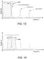
- FIG. 14 provides an example illustration of a tuned bandwidth 1402 of the band-pass filters 1216 and 1217.
- the tuned bandwidth 1402 of the band-pass filters 1216 and 1217 is illustrated as being adjustable. As described above, the bandwidth 1402 of the band-pass filters 1216 and 1217 is adjusted based on the control signal 1239 generated by the PID controller 1238.
- the output pulse train signal P out may be provided to the engine controller of an aircraft, so that the engine controller has feedback regarding the speed of the rotor 130.
- the embodiment of the MPM illustrated in FIG. 12 seeks to provide a pulse train output signal representative of the speed of the bladed rotor 130 as does the embodiment of the MPM illustrated in FIG. 8 .
- proximity sensors other than microwave probes may be used. If a proximity sensor other than a microwave probe is used, in certain embodiments, a reflected signal received by the proximity sensor may be down-converted without using separate in-phase and quadrature channels. In this case, the configuration of FIG. 12 may be modified to rely on only one of the in-phase and quadrature sections. In other words, without separate in-phase and quadrature down-converted channels, the configuration of FIG. 12 may be modified for only a single channel similar to either one of the in-phase or quadrature sections.
- FIGS. 15-18 Before turning to the process flow diagrams of FIGS. 15-18 , it is noted that the present invention may be practiced using an alternative order of the steps illustrated in FIGS. 15-18 . That is, the process flows illustrated in FIGS. 15-18 are provided as examples only, and the present invention may be practiced using process flows that differ from those illustrated. Additionally, it is noted that not all steps are required in every embodiment. In other words, one or more of the steps may be omitted or replaced, without departing from the spirit and scope of the invention. In alternative embodiments, steps may be performed in different orders, in parallel with one another, or omitted entirely, and/or certain additional steps may be performed without departing from the scope and spirit of the invention.
- FIG. 16 one embodiment of the generation of an output pulse train signal at step 1540 is described in further detail.
- the process of the generation of the output pulse train signal illustrated in FIG. 16 is described in connection with the system elements illustrated in FIG. 8 , but may be practiced with other equivalent elements as understood by one having skill in the art.
- the in-phase energy detector 822 detects a mean energy of an in-phase portion of the down-converted signal and, at step 1620, the quadrature energy detector 824 detects a mean energy of a quadrature portion of the down-converted signal.
- the summer 826 sums the mean energy of the in-phase portion of the down-converted signal and the mean energy of the quadrature portion of the down-converted signal as a total mean energy of the down-converted signal.
- the bank of sub-band filters 810 band-pass filters the in-phase portion of the down-converted signal to provide an in-phase band-passed signal at step 1640, detects a mean energy of the in-phase band-passed signal at step 1650, detects zero-crossings of the in-phase band-passed signal at step 1660, and generates an in-phase pulse train signal based on the zero-crossings of the in-phase band-passed signal at step 1670.
- the bank of sub-band filters 811 band-pass filters the quadrature portion of the down-converted signal to provide a quadrature band-passed signal at step 1642, detects a mean energy of the quadrature band-passed signal at step 1652, detects zero-crossings of the quadrature band-passed signal at step 1662, and generates a quadrature pulse train signal based on the zero-crossings of the quadrature band-passed signal at step 1672.
- step 1680 for each of the plurality of sub-bands of the down-converted signal, the bank of sub-band energy detectors 830 sums the mean energies of the in-phase and quadrature band-passed signals as a total mean sub-band energy.
- step 1680 the process proceeds to step 1710, as illustrated in FIG. 17 , where, for each of the plurality of sub-bands of the down-converted signal, the bank of sub-band energy detectors 830 compares the total mean sub-band energy to the total mean energy of the down-converted signal to provide a sub-band selection signal.
- the selection logic 844 generates control signals based on the sub-band selection signals and, at step 1720, the in-phase sub-band selector 842 selects an in-phase pulse train signal among the in-phase pulse train signals of the plurality of sub-bands for output as a selected in-phase pulse train signal based on the control signals.
- the quadrature sub-band selector 846 selects a quadrature pulse train signal among the quadrature pulse train signals of the plurality of sub-bands for output as a selected quadrature pulse train signal based on the control signals.
- the I/Q output selector generates the output pulse train signal by selecting one of the selected in-phase pulse train signal and the selected quadrature pulse train signal as the output pulse train signal representative of the speed of the bladed rotor.
- FIG. 18 another embodiment of the generation of an output pulse train signal at step 1540 is described in further detail.
- the process of the generation of the output pulse train signal illustrated in FIG. 18 is described in connection with the system elements illustrated in FIG. 12 , but may be practiced with other equivalent elements as understood by one having skill in the art.
- the band-pass filter 1210 passes frequencies of the down-converted signal corresponding to a fundamental frequency of the down-converted signal and rejects other frequencies to generate a band-passed signal.
- the tunable low-pass filters 1222 and 1242 filter the band-passed signal in response to a control signal to provide a filtered output.
- the energy detectors 1226 and 1246 produce a first mean energy output based on the filtered output of the tunable low-pass filters 1222 and 1242. Further, at step 1840, the energy detectors 1224 and 1244 produce a second mean energy based on the band-passed signal.
Landscapes
- Engineering & Computer Science (AREA)
- Radar, Positioning & Navigation (AREA)
- Remote Sensing (AREA)
- Physics & Mathematics (AREA)
- General Physics & Mathematics (AREA)
- Computer Networks & Wireless Communication (AREA)
- Electromagnetism (AREA)
- Radar Systems Or Details Thereof (AREA)
Description
- The present invention generally relates to the measurement of the speed of blade rotors in a turbine engine and, more particularly, to the measurement of the speed of bladed rotors in a turbine engine using microwave probes and various embodiments of analog and digital circuitry.
- Sensing systems are employed for a wide variety of purposes. Sensing systems may detect motion of an object or environmental conditions, for example. Sensing applications are applicable to many industries such as medical, processing, transportation, and aeronautics industries, among others. Because of the diversity in purpose for sensing systems, many considerations must be considered by engineers when designing a new sensing system. Considerations such as cost, precision, measurement range, durability, maintenance, and even physical characteristics are generally considered by engineers.
- Non-contact sensing systems are sensing systems that, unlike contact sensing systems, do not require a sensor to physically contact an object being measured. Non-contact sensing systems offer many advantages over contact sensing systems, such as the ability to provide information regarding an object and/or condition of interest without expensive and invasive sensor mounting assemblies. Non-contact systems, unlike contact systems, are also advantageous because they do not impact the system they measure. Radar systems include one example of a non-invasive sensing system. Radar systems use transmitted and reflected radio waves, typically on the order of 0.9-100 GHz, to determine the presence, location, and/or speed of objects. Some radar systems operate by transmitting either a constant continuous wave (CW) signal or a pulsed signal. Most CW radar systems operate under the principle of the Doppler effect, in which the change in reflected signal phase and/or frequency with respect to a transmitted signal phase and frequency is measured. CW radar systems that rely on the Doppler effect provide a mechanism of detecting a moving object by transmitting microwaves at a targeted object and detecting the change in frequency and/or phase of microwave signals reflected from the object.
- Further, non-contact radar techniques provide a sensing mechanism that is relatively unaffected by temperature, dust, debris, water, and many other obscurants when the proper transmit frequencies are used. Radar sensing systems may accurately provide information on the speed, location, and direction of movement of targets being sensed, as compared to other less-accurate sensing systems. One need in aeronautics or power generation applications, for example, would be to determine accurately the speed of a turbine engine and, particularly, the speed of one or more bladed rotors in a turbine engine.
-
US 4 131 889 A discloses that an oscillator is repetitively pulsed on and off by a pulse generator. During the pulses microwaves are generated which are transmitted into free space towards a moving target. Return signals reflected from the target are mixed in a mixer diode with a reference signal comprising a fraction of the pulses signal generated by the oscillator. The output of the mixer diode consists of pulses which are applied to an integrator via a gate, controlled by pulses from the pulse generator. The output of the integrator is filtered by a narrow band amplifier/filter and is fed into a comparator where it is compared with a threshold voltage VT. If the output of the amplifier/filter is above the threshold voltage VT the comparator produces an output which operates an indicator. Target speed may be measured simply by measuring the frequency of the output signal from the filter. In one embodiment the return signal detected by the receive antenna is divided into two signals by a rat race which is a device which also shifts the phase of one of the signals. -
US 4573 358 A discloses an apparatus for monitoring the individual blades of a blade row in a turbo machine which includes a plurality of sensors equally spaced about the periphery of the blade row. Each sensor is of the type which will provide an output signal as a blade passes it. Signal conditioning means are provided for each sensor to convert its output signal into a corresponding narrow pulse signal. Means are provided for combining all of the sensor pulse signals caused by the selected blade passing each of the sensors during rotation of the blade row. The combined output is a pulse train signal which is modulated as a function of blade vibration with the pulses being evenly spaced in the absence of any blade vibration. The pulse train signal is frequency demodulated with the results of such demodulation being utilized to determine blade vibration. -
US 2008/195338 A1 discloses an exemplary process for blade tip measurements. In-phase and quadrature data are collected by a receiver of the microwave sensor, the data associated with, at least in part, microwave energy reflected by the blades and the casing. A complex Fast Fourier Transform (FFT) is performed on the in-phase (I) and quadrature (Q) data to generate positive frequency components and negative frequency components. - In this context, the present invention is directed to addressing deficiencies of conventional measurement systems with systems and methods for accurately sensing the speed of a moving object such as a bladed rotor of a turbine engine. This and other objects can be achieved by the apparatus and method as defined in the independent claims. Further enhancements are characterized in the dependent claims.
- In one embodiment, an apparatus for measuring bladed rotors is described, including a microwave sensor that radiates a microwave signal toward a bladed rotor and receives a reflected microwave signal from the bladed rotor, a radio frequency module that generates the microwave signal radiated by the microwave sensor and down-converts the reflected microwave signal into a down-converted signal, and a main processing module configured to generate an output pulse train signal representative of a speed of the bladed rotor based on the down-converted signal.
- In certain aspects, the main processing module comprises a bank of sub-band filters, a signal energy detector, a bank of sub-band energy detectors, a sub-band selector, and an in-phase/quadrature output selector. Further, the signal energy detector may comprise an in-phase energy detector that detects a mean energy of an in-phase portion of the down-converted signal, a quadrature energy detector that detects a mean energy of a quadrature portion of the down-converted signal, and a summer that sums the mean energy of the in-phase portion of the down-converted signal and the mean energy of the quadrature portion of the down-converted signal as a total mean energy of the down-converted signal.
- In other aspects, the bank of sub-band filters comprises a plurality of sub-band filter pairs, each sub-band filter pair comprises an in-phase sub-band filter and a quadrature sub-band filter, each in-phase sub-band filter comprises a band-pass filter that provides an in-phase band-passed signal based on the in-phase portion of the down converted signal, a mean energy detector that detects a mean energy of the in-phase band-passed signal, and a zero-crossing detector that detects zero-crossings of the in-phase band-passed signal and generates an in-phase pulse train signal based on the zero-crossings of the in-phase band-passed signal, and each quadrature sub-band filter comprises a band-pass filter that provides a quadrature band-passed signal based on the quadrature portion of the down converted signal, a mean energy detector that detects a mean energy of the quadrature band-passed signal, and a zero-crossing detector that detects zero-crossings of the quadrature band-passed signal and generates a quadrature pulse train signal based on the zero-crossings of the quadrature band-passed signal.
- In other aspects, the bank of sub-band energy detectors comprises a plurality of sub-band energy detectors, and each sub-band energy detector comprises a summer that sums the mean energy of the in-phase band-passed signal and the mean energy of the quadrature band-passed signal from a respective in-phase and quadrature sub-band filter pair as a total mean sub-band energy, and a comparator that compares the total mean sub-band energy to the total mean energy of the down-converted signal and provides a sub-band selection signal. Further, in certain embodiments, the sub-band selector comprises selection logic, an in-phase sub-band selector, and a quadrature sub-band selector, the selection logic generates control signals for the in-phase sub-band selector and the quadrature sub-band selector based on the sub-band selection signals from the sub-band energy detectors, the in-phase sub-band selector selects an in-phase pulse train signal among the in-phase pulse train signals generated from the in-phase sub-band filters for output as a selected in-phase pulse train signal based on the control signals, and the quadrature-phase sub-band selector selects a quadrature pulse train signal among the quadrature pulse train signals generated from the quadrature sub-band filters for output as a selected quadrature pulse train signal based on the control signals.
- In still other aspects, the in-phase/quadrature output selector may output one of the selected in-phase pulse train signal and the selected quadrature pulse train signal as the output pulse train signal representative of the speed of the bladed rotor. In other embodiments, the in-phase/quadrature output selector is configured to select one of the selected in-phase pulse train signal and the selected quadrature pulse train signal for output as the output pulse train signal representative of the speed of the bladed rotor, and maintain the selection of the one of the pulse train signals for output until a predetermined number of falling or rising edges occurs on another one of the pulse train signals while no falling or rising edges occur on the selected one of the pulse train signals.
- In another embodiment, a method for measuring bladed rotors is described, including radiating a microwave signal toward a bladed rotor, receiving a reflected microwave signal from the bladed rotor, down-converting the reflected microwave signal into a down-converted signal, and generating an output pulse train signal representative of a speed of the bladed rotor based on the down-converted signal. In certain aspects, generating the output pulse train signal further includes detecting a mean energy of an in-phase portion of the down-converted signal and a mean energy of a quadrature portion of the down-converted signal, summing the mean energy of the in-phase portion of the down-converted signal and the mean energy of the quadrature portion of the down-converted signal as a total mean energy of the down-converted signal.
- In other aspects, generating the output pulse train signal further comprises, for each of a plurality of sub-bands of the down-converted signal, band-pass filtering the in-phase portion of the down-converted signal to provide an in-phase band-passed signal, detecting a mean energy of the in-phase band-passed signal, detecting zero-crossings of the in-phase band-passed signal, generating an in-phase pulse train signal based on the zero-crossings of the in-phase band-passed signal, band-pass filtering the quadrature portion of the down-converted signal to provide a quadrature band-passed signal, detecting a mean energy of the quadrature band-passed signal, detecting zero-crossings of the quadrature band-passed signal, and generating a quadrature pulse train signal based on the zero-crossings of the quadrature band-passed signal.
- In still other aspects, generating the output pulse train signal further includes, for each of the plurality of sub-bands of the down-converted signal, summing the mean energies of the in-phase and quadrature band-passed signals as a total mean sub-band energy, and comparing the total mean sub-band energy to the total mean energy of the down-converted signal to provide a sub-band selection signal. Further, in other aspects, generating the output pulse train signal further includes generating control signals based on the sub-band selection signals, selecting an in-phase pulse train signal among the in-phase pulse train signals of the plurality of sub-bands for output as a selected in-phase pulse train signal based on the control signals, and selecting a quadrature pulse train signal among the quadrature pulse train signals of the plurality of sub-bands for output as a selected quadrature pulse train signal based on the control signals. Additionally, in other aspects, generating the output pulse train signal further includes selecting one of the selected in-phase pulse train signal and the selected quadrature pulse train signal as the output pulse train signal representative of the speed of the bladed rotor.
- In another embodiment, an apparatus for measuring bladed rotors is described, including a microwave sensor that radiates a microwave signal toward a bladed rotor and receives a reflected microwave signal from the bladed rotor, a radio frequency module that generates the microwave signal radiated by the microwave sensor and down-converts the reflected microwave signal into a down-converted signal, and a main processing module comprising a band-pass filter, a tracking filter , a digital pulse generator, and an in-phase/quadrature output selector, the main processing module being configured to generate an output pulse train signal representative of a speed of the bladed rotor based on the down-converted signal. In certain aspects, the band-pass filter passes frequencies of the down-converted signal corresponding to a fundamental frequency of the down-converted signal and rejects other frequencies to generate a band-passed signal. Further, in certain aspects, the tracking filter further includes a tunable low-pass filter and mean energy detector that low-pass filters the band-passed signal based on a control signal and generates a first mean energy output based on an output of the low-pass filter, a second mean energy detector that determines a second mean energy output based on the band-passed signal, and a controller that generates the control signal based on a difference between the first and second mean energy outputs.
- In other aspects, the digital pulse generator comprises a second tunable filter that filters the band-passed signal based on the control signal, and a pulse generator that detects zero-crossings of the signal output by the second tunable filter and generates a pulse train signal based on the zero-crossings. Further, in other aspects, the digital pulse generator comprises in-phase and quadrature pulse generators, the in-phase pulse generator further comprises an in-phase tunable filter that filters an in-phase portion of the band-passed signal based on the control signal, and the quadrature pulse generator further comprises a quadrature tunable filter that filters a quadrature portion of the band-passed signal based on the control signal.
- In still other aspects, the in-phase pulse generator further comprises an in-phase pulse generator that detects zero-crossings of the signal output by the in-phase tunable filter and generates an in-phase pulse train signal based on the in-phase zero-crossings, and the quadrature pulse generator further comprises a quadrature pulse generator that detects zero-crossings of the signal output by the quadrature tunable filter and generates a quadrature pulse train signal based on the quadrature zero-crossings. Further, in other aspects, the in-phase/quadrature output selector outputs one of the in-phase pulse train signal and the quadrature pulse train signal as the output pulse train signal representative of the speed of the bladed rotor.
- In another embodiment, a method for measuring bladed rotors is described, including radiating a microwave signal toward a bladed rotor, receiving a reflected microwave signal from the bladed rotor, down-converting the reflected microwave signal into a down-converted signal, and generating an output pulse train signal representative of a speed of the bladed rotor based on the down-converted signal, wherein generating the output pulse train signal further comprises passing frequencies of the down-converted signal corresponding to a fundamental frequency of the down-converted signal and rejecting other frequencies to generate a band-passed signal, and filtering the band-passed signal in response to a control signal to provide a filtered output.
- In one aspect, the method further includes producing a first mean energy output based on the filtered output, and producing a second mean energy based on the band-passed signal. In other aspects, the method further includes generating the control signal based on a difference between the first and second mean energy outputs. Further, in other aspects, the method further includes second filtering the band-passed signal in response to the control signal to provide a second filtered output, detecting zero-crossings of the second filtered output, and generating the output pulse train signal based on the zero-crossings.
- In another embodiment, an apparatus for measuring bladed rotors is described, including a sensor that radiates a signal toward a bladed rotor and receives a reflected signal from the bladed rotor, a radio frequency module that generates the signal radiated by the sensor and down-converts the reflected signal into a down-converted signal, and a main processing module configured to generate an output pulse train signal representative of a speed of the bladed rotor based on the down-converted signal. In one aspect, the main processing module includes a bank of sub-band filters, a signal energy detector, a bank of sub-band energy detectors, and a sub-band selector, and the signal energy detector detects a mean energy of the down-converted signal. In other aspects, the bank of sub-band filters comprises a plurality of sub-band filters, and each sub-band filter comprises a band-pass filter that provides a band-passed signal based on the down converted signal, a mean energy detector that detects a mean energy of the band-passed signal, and a zero-crossing detector that detects zero-crossings of the band-passed signal and generates a pulse train signal based on the zero-crossings of the band-passed signal.
- In certain aspects, the bank of sub-band energy detectors includes a plurality of sub-band energy detectors, and each sub-band energy detector comprises a comparator that compares the mean energy of a respective one of the band-passed signals to the mean energy of the down-converted signal and provides a sub-band selection signal. Further, in one embodiment, the sub-band selector comprises selection logic and a sub-band selector, the selection logic generates control signals for the sub-band selector based on the sub-band selection signals from the sub-band energy detectors, and the sub-band selector selects a pulse train signal among the pulse train signals generated from the sub-band filters for output as the output pulse train signal based on the control signals.
- In still another embodiment, an apparatus for measuring bladed rotors is describe, including a sensor that radiates a signal toward a bladed rotor and receives a reflected microwave signal from the bladed rotor, a radio frequency module that generates the signal radiated by the sensor and down-converts the reflected signal into a down-converted signal, and a main processing module comprising a band-pass filter, a tracking filter , and a digital pulse generator, the main processing module being configured to generate an output pulse train signal representative of a speed of the bladed rotor based on the down-converted signal. In one aspect, the band-pass filter passes frequencies of the down-converted signal corresponding to a fundamental frequency of the down-converted signal and rejects other frequencies to generate a band-passed signal.
- In other aspects, the tracking filter further comprises a tunable low-pass filter and mean energy detector that low-pass filters the band-passed signal based on a control signal and generates a first mean energy output based on an output of the low-pass filter, a second mean energy detector that determines a second mean energy output based on the band-passed signal, and a controller that generates the control signal based on a difference between the first and second mean energy outputs. Further, in one embodiment, the digital pulse generator comprises a second tunable filter that filters the band-passed signal based on the control signal, and a pulse generator that detects zero-crossings of the signal output by the second tunable filter and generates the output pulse train signal based on the zero-crossings.
- These and other aspects, objects, features, and embodiments will become apparent to a person of ordinary skill in the art upon consideration of the following detailed description of illustrative embodiments exemplifying the best mode for carrying out the invention as presently perceived.
- For a more complete understanding of the invention and the advantages thereof, reference is now made to the following description, in conjunction with the accompanying figures briefly described as follows.
-
FIG. 1 illustrates a speed measurement system according to one embodiment; -
FIG. 2 provides an illustration of a principle for speed measurement according to certain aspects of the present invention; -
FIG. 3A illustrates an example embodiment of a housing for an electronics unit of a speed measurement system; -
FIG. 3B illustrates an example embodiment of an arrangement of electronic circuit boards within the housing illustrated inFIG. 3A ; -
FIG. 4 illustrates a high-level block diagram of an example embodiment of an electronics unit for a speed measurement system; -
FIG. 5 illustrates an example embodiment of a Radio-Frequency Module according to certain aspects of the present invention; -
FIG. 6A illustrates an example of In-phase and Quadrature signal portions of a reflected microwave signal; -
FIG. 6B illustrates an example of a reflected microwave signal in the In-phase/Quadrature plane; -
FIGS. 7A and 7B illustrate examples of waveform variations based on probe-to-blade distance variations; -
FIGS. 7C and 7D illustrate examples of waveform variations based on transmission frequency variations; -
FIG. 8 illustrates an example schematic diagram of one embodiment of a main processing module according to certain aspects of the present invention; -
FIG. 9 provides an illustration of a fundamental frequency principle according to certain aspects of the present invention; -
FIG. 10 provides an illustration of a sub-band bandwidth principle according to certain aspects of the present invention; -
FIG. 11 provides an illustration of a signal selection principle according to certain aspects of the present invention; -
FIG. 12 illustrates an example schematic diagram of another embodiment of a main processing module according to certain aspects of the present invention; -
FIG. 13 provides an example illustration of a tuned bandwidth of a low-pass filter according to certain aspects of the present invention; -
FIG. 14 provides an example illustration of a tuned bandwidth of a band-pass filter according to certain aspects of the present invention; -
FIG. 15 illustrates an example embodiment of a method for speed measurement of bladed rotors; -
FIG. 16 illustrates an example embodiment of a method for generating an output pulse train representative of a speed of a bladed rotor; -
FIG. 17 further illustrates the example embodiment of a method for generating an output pulse train representative of a speed of a bladed rotor; and -
FIG. 18 illustrates another embodiment of a method for generating an output pulse train representative of a speed of a bladed rotor. - The drawings illustrate only exemplary embodiments of the invention and are therefore not to be considered limiting of its scope, as the invention may admit to other equally effective embodiments. The elements and features shown in the drawings are not necessarily to scale, emphasis instead being placed upon clearly illustrating the principles of the exemplary embodiments. Additionally, certain dimensions or positionings may be exaggerated to help visually convey such principles.
- In the following paragraphs, the present invention will be described in further detail by way of example with reference to the attached drawings. In the description, well known components, methods, and/or processing techniques are omitted or briefly described so as not to obscure the invention. As used herein, the "present invention" refers to any one of the embodiments of the invention described herein and any equivalents. Furthermore, reference to various feature(s) of the "present invention" is not to suggest that all embodiments must include the referenced feature(s).
- At the outset, technology features that differentiate microwave technology from other technologies for bladed rotor measurement are described. It is noted that microwave sensing is relatively insensitive to contaminants such as those within an engine. Microwave signals generally pass directly through contaminants from engine environments. Even when microwave probe tips are completely coated with carbon using an acetylene torch without oxygen, the probe tips have been shown to operate suitably for microwave measurements. In such cases, heavy carbon coatings on probe tips absorb a small portion of microwaves, but measurements are generally left unaffected. Long-term operation has confirmed such results in several instances.
- The microwave systems described herein are able to operate with high signal-to-noise ratios even at extended ranges. Further, microwave systems permit measurements to be taken at relatively large distances between microwave probes and objects being measured. Overall signal-to-noise ratios are affected as distance to target objects increase, but, for speed measurement, distances up to 100 mm or more may be suitable. The microwave systems described herein also have a naturally large bandwidth and are designed with a flat frequency response over a range of speeds to be measured. This allows for reliable measurements throughout an entire operating range of an engine being measured.
- In some aspects, microwave probes and microwave transmission cables are more prone to failure, because these components may be placed in high temperature and vibration regions of an engine being measured. An exemplary location of a microwave probe for measurement of a bladed rotor of a turbine engine is in front of the stage to be measured, looking aft at an angle relative to the shaft center-line of the bladed rotor. In this way, individual blades of the bladed rotor pass in front of the sensor. Another option is to aim the microwave probe directly down at the blade tips. This configuration provides an interrupted blade signal to generate the speed information. In general, any position in which the microwave probe faces an "interrupted" pattern of the object being measured and free space, such as facing gear teeth, fan blades, and mixing blades, for example, is a candidate for speed measurement.
- The microwave probes used in the embodiments described herein are designed for high-temperature applications. The survivability of a microwave probe depends, in part, upon the mechanical design, material, and joining technology used to manufacture the probe. The high-temperature front-end of the microwave probes includes a ceramic window, which serves to protect the internal microwave elements but is transparent to the microwaves. The ceramic and metal elements of the probes are joined together using high temperature braze procedures above 1300°C. For many embodiments described herein, the probes do not require bleed cooling air. The mechanical parts and materials selected for the probes are chosen to reduce thermal expansion. Behind the ceramic window, the microwave antenna structure of the microwave probe is relatively simple and robust in terms of survival.
- One aspect of the survivability of the microwave probes is maintaining a hermetic seal with the cable that supplies the microwave signal for transmission, so that no contamination of occurs. Normally, the primary failure mode of microwave probes is the loss of hermeticity in this joint due to harsh temperature cycling and thermal expansion mismatch between the probe and the joint of the cable. In certain embodiments, to mitigate this risk, primary seal and backup seals may be relied upon. The first line of protection for the probe is the primary seal at the ceramic window. This joint is designed to survive 1st stage turbine temperatures. However, if this seal were to break, the probe is expected to have minimal degradation as the internal parts of the probe may be plated with platinum, for example, to keep them from oxidizing. The second seal will be an additional hermetic feed at the cable. As long as the ceramic window maintains mechanical integrity and the cable feed is hermetic, the probe will continue to operate. Any failure of the probe due to cable contamination is likely to manifest itself as a slow loss in signal over time.
- Turning now to the drawings, in which like numerals indicate like, but not necessarily the same, elements throughout, exemplary embodiments of the invention are described in detail.
-
FIG. 1 illustrates aspeed measurement system 100 according to one embodiment of the present invention. Thesystem 100 includes anengine 102, anelectronics unit 110, and at least onemicrowave probe 120 coupled to theelectronics unit 110 viacoupling 112. Among embodiments, theengine 102 may comprise any gas turbine, rotary, or similar engine, without limitation. Among other elements as understood in the art, theengine 102 comprises at least onebladed rotor 130 connected to ashaft 140. Theengine 102 operates based on the compression of intake air by a rotary compressor or turbine for a combustion cycle that generates thrust. As illustrated inFIG 2 , thebladed rotor 130 comprises a plurality ofblades 132 which cause therotor 130 to turn about an axis of symmetry when combustion exhaust is forced over them, turning theshaft 140. As described herein, thebladed rotor 130 is a rotor within a hot section of theengine 102. However, it is noted that theengine 102 may comprise a plurality of bladed rotors and that any bladed rotor(s) or other "interrupted" pattern of theengine 102 may be measured using thesystem 100. WhileFIG. 1 illustrates twomicrowave sensors 120, embodiments incorporating one or more than two sensors are within the scope of the disclosure. Further, it is noted that, in alternative embodiments, proximity sensors other than microwave probes may be used. In that case, theelectronics unit 110 may be modified as compared to when microwave probes are used, as described in further detail below. - The microwave probes 120 are adapted to radiate a microwave signal and receive a reflected microwave signal. In
FIG. 1 , the microwave probes 120 are adapted to radiate a microwave signal toward thebladed rotor 130 and receive a reflected microwave signal from thebladed rotor 130. Based on the radiation of microwave signals and the receipt of reflected microwave signals, the microwave probes 120 are used to measure the rotation of thebladed rotor 130 at relatively long distances and in the harsh environment of the hot combustion section of theengine 102. In the context of speed measurement of theengine 102 when the engine is attached to an aircraft to provide trust, theelectronics unit 110 andmicrowave probes 120 are configured to measure the speed of therotor 130 and, more particularly, the rate at which theblades 132 rotate about theshaft 140. In an embodiment where thesystem 100 is implemented in an aircraft, theelectronics unit 110 may be configured to interface directly with an engine controller of the aircraft to provide a digital signal, such as a digital pulse train, indicating the rate of rotation or speed of therotor 130 and theblades 132. - With reference again to
FIG. 2 , an illustration of a principle for speed measurement according to certain aspects of the present invention is described. Generally, a continuous microwave signal is generated, transmitted, and radiated toward theblades 132. The microwave signal is reflected off theblades 132 as a reflected microwave signal, and the reflected microwave signal is captured and returned for processing. In certain embodiments, the processing includes comparing the reflected microwave signal with a reference signal representative of the originally generated and transmitted microwave signal, to identify amplitude and phase modulations of the reflected microwave signal caused by the rotated reflection of theblades 132. - The microwave signal may be a microwave signal having a frequency of 6 or 24 GHz, for example. In terms of the
system 100, theelectronics unit 110 generates the continuous microwave signal and transmits the microwave signal to the microwave probes 120 via thecouplings 112 for radiation of the microwave signal. Thecouplings 112 may comprise any suitable transmission line for microwave signals and, preferably, be hermetically joined to themicrowave sensors 120. The microwave probes 120 radiate the microwave signal towards theblades 132 and receive a reflected microwave signal from theblades 132 which is returned via thecouplings 112 to theelectronics unit 110 for processing. Theelectronics unit 110 compares the reflected microwave signal with the reference signal and analyzes the amplitude and phase modulations of the reflected microwave signal to generate an output signal representative of a speed of thebladed rotor 130. Among embodiments described herein, theelectronics unit 110 comprises analog, digital, or combinations of analog and digital circuitry to generate the output signal as described in further detail below. -
FIG. 3A illustrates an example embodiment of ahousing 300 for an electronics unit of a speed measurement system andFIG. 3B illustrates an example embodiment of an arrangement of electronic circuit boards within thehousing 300 illustrated inFIG. 3A . Thehousing 300 illustrated inFIG. 3A is an example embodiment of a housing for theelectronics unit 110. As illustrated, thehousing 300 includes a microwave I/O port and a power and control Input/Output (I/O) port. The microwave I/O port may be coupled to thecouplings 112 for transmission and return of microwave signals to and from the microwave probes 120. Among other couplings, the control I/O port may be coupled to a power source for theelectronics unit 110 and to the engine controller of an aircraft, as described above. Thehousing 300 may be formed from any material suitable for the application such as aluminum or other metals or plastic, for example, and thehousing 300 may comprise several sections fastened together with screws, rivets, or other fasteners, as suitable and necessary for the application. One or more electronic circuit boards of theelectronics unit 100 may be stacked and enclosed within thehousing 300. For example, the circuit boards may include a Radio Frequency Module (RFM), a Main Processing Module (MPM), and a Power Supply Module (PSM), among others, as described in further detail below. - Turning to
FIG. 4 , a high-level block diagram of an example embodiment of theelectronics unit 110 is described in further detail. As illustrated, theelectronics unit 110 includes anRFM 420, anMPM 410, and aPSM 430. As described in further detail below, theRFM 420 generates a microwave signal for radiation by at least one microwave probe, such as the microwave probes 120, based on the control of theMPM 410. In turn, the microwave probes 120 radiate the microwave signal toward thebladed rotor 130 and capture reflected microwave signals reflected from thebladed rotor 130, as noted above. TheRFM 420 receives the reflected microwave signal from the microwave probes 120, down-converts the reflected microwave signal into a down-converted signal, and passes the down-converted signal to theMPM 410 for additional processing. TheMPM 410 is configured to generate an output pulse train signal representative of a speed of thebladed rotor 130 based on the down-converted signal. In one embodiment, thePSM 430 comprises a Direct-Current to Direct-Current (DC/DC) converter, as would be understood in the art. As such, thePSM 430 is configured to receive power at a first voltage and generate power for theelectronics unit 110 at one or more second voltages based on the received power. As one non-limiting example, thePSM 430 is configured to receive a 12 VDC input and generate output voltages at 5 VDC, 4 VDC, 3.3 VDC, 2.5 VDC, and 1.2 VDC, as necessary for the various circuitry of theelectronics unit 110, although other input and output voltages of thePSM 430 are within the scope of the disclosure. - Turning to
FIG. 5 , an example embodiment of theRFM 420 is described in further detail. According to the illustrated example, theRFM 420 comprises a Phase Locked Loop (PLL) 502, a Voltage Controlled Oscillator (VCO) 504, apower splitter 506, Radio Frequency (RF)amplifiers directional coupler 509, In-phase and Quadrature (I/Q)mixers 512, andamplifiers 516. As illustrated, theRFM 420 receives power from thePSM 430 and an RF control signal from theMPM 410. Based on the RF control signal from theMPM 410, thePLL 502 andVCO 504 generate a microwave signal at a desired frequency for microwave radiation (i.e., 6 or 24 GHz). In certain embodiments, the RF control signal from theMPM 410 is a microwave signal at the desired microwave frequency and thePLL 502 andVCO 504 frequency and phase lock to the RF control signal from theMPM 410. In other embodiments, the RF control signal comprises a signal having a frequency that is a ratio of the desired microwave frequency, and the PLL andVCO 504 lock to and multiply the frequency of the RF control signal from theMPM 410 to generate the microwave signal at the desired frequency for microwave radiation. In still other embodiments, the RF control signal comprises a control voltage, and thePLL 502 andVCO 504 generate the microwave signal at the desired frequency for radiation based on the control voltage. - The
power splitter 506 splits the microwave signal generated by thePLL 502 andVCO 504. One output of thepower splitter 506 is provided to theRF amplifier 508 and theRF amplifier 508 amplifies the microwave signal for radiation by the microwave probes 120. Another output of thepower splitter 506 is provided to theRF amplifier 510 and theRF amplifier 510 amplifies and provides the microwave signal to the I/Q mixers 512 for mixing with the reflected microwave signal returned by the microwave probes 120 to provide a down-converted signal including I/Q portions. Specifically, over the same path (i.e., couplings 121) that the microwave signal is provided by theRF amplifier 508 for radiation by the microwave probes 120, a reflected microwave signal is returned by the microwave probes 120. The reflected microwave signal is coupled to the I/Q mixers 512 by thedirectional coupler 509 and the I/Q mixers 512 mix the reflected microwave signal with the output of theRF amplifier 510 to provide a down-converted signal including I/Q portions. It is noted that the I/Q mixers includes aphase shifter 513 that provides I and Q portions of the reference output of theRF amplifier 510 for down-conversion. - Thus, with reference back to the illustration of
FIG. 2 , the output of theRF amplifier 508 corresponds to the transmitted microwave signal, the output of theRF amplifier 510 corresponds to the reference microwave signal, and the output of theRF amplifier 509 corresponds to the reflected microwave signal. In one embodiment, the down-converted signal output by the I/Q mixers 512 is amplified by theamplifiers 516 before being provided to theMPM 410. In other embodiments, theamplifiers 516 may be omitted or integrated as part of theMPM 410. Additionally, it is noted that the amount of amplification provided respectively by theRF amplifiers - With reference to
FIG. 6A , an example of I/Q signal portions of a down-converted signal output by the I/Q mixers 512 is described. Particularly, inFIG. 6A , example I/Q signal portions are illustrated over time for two periods of blade microwave reflection. As described in additional detail below, the I/Q signal portions are processed by theMPM 410 to generate an output pulse train signal representative of a speed of a bladed rotor, such as the speed of thebladed rotor 130. It is noted that, in certain embodiments, theMPM 410 may select one of the I or the Q portions of the down-converted signal over time to generate the output pulse train. The selection of the one of the I or the Q portions of the down-converted signal may depend upon, for example, rotation of the I/Q signal portions in the I/Q signal plane, which may depend upon various factors such as probe-to-blade distance and changes in the frequency of the radiated microwave signal over time, for example. These factors may depend in part upon environmental conditions such as temperature and humidity changes over time. With reference toFIG. 6B , an example of the I/Q signal portions in the I/Q signal plane is illustrated. In the I/Q signal plane, the down-converted signal may appear to oscillate along a continuous path at a rate determined according to the speed of thebladed rotor 130. TheMPM 410 is configured to determine the rate at which the down-converted signal traverses from opposing ends of the continuous path illustrated inFIG. 6B , for example, as a measure of the speed of thebladed rotor 130. - As noted above, the shape and position of the waveform illustrated in
FIG. 6B may vary over time based on various factors such as probe-to-blade distance and frequency change of the radiated microwave signal over time. Examples of the impact of these factors on the I/Q signal portions in the I/Q signal plane are illustrated inFIGS. 7A-7D . As compared to the waveform illustrated inFIG. 6B , the waveform illustrated inFIG. 7A has experienced a counter-clockwise rotation and decreased magnitude in response to an increased probe-to-blade distance. In contrast, as compared to the waveform illustrated inFIG. 6B , the waveform illustrated inFIG. 7B has experienced a clockwise rotation and increased magnitude in response to a decreased probe-to-blade distance. The waveform illustrated inFIG. 7C has experienced a counter-clockwise rotation in response to an increased frequency of the radiated microwave signal over time. In contrast, the waveform illustrated inFIG. 7D has experienced a clockwise rotation in response to a decreased frequency of the radiated microwave signal over time. As described in further detail below, theMPM 410 is designed and configured to generate an output pulse train signal representative of the speed of thebladed rotor 130 based on the down-converted signal output by the I/Q mixers 512, even when the I/Q signal portions of the down-converted signal vary over time as illustrated inFIGS. 7A-7D . - Turning to
FIG. 8 , an example schematic diagram of one exemplary embodiment of theMPM 410 is described in detail. The embodiment of theMPM 410 illustrated inFIG. 8 may be implemented by analog, digital, or a combination of analog and digital circuitry, as understood by one having ordinary skill in the art. As described herein, however, theMPM 410 illustrated inFIG. 8 is implemented by analog circuitry. That is, the embodiment of theMPM 410 illustrated inFIG. 8 is implemented without any signal conversion using an analog-to-digital (A/D) converter. As illustrated, theMPM 410 includes a bank ofsub-band filters signal energy detector 820, a bank ofsub-band energy detectors 830, asub-band selector 840, and an I/Q output selector 850. Thesignal energy detector 820 includes an in-phase energy detector 822 that detects a mean energy of the I portion of the down-converted signal (Iin), aquadrature energy detector 824 that detects a mean energy of the Q portion of the down-converted signal (Qin), and asummer 826 that sums the mean energies of the I and Q portions of the down-converted signal to provide a total mean energy signal, Etot, of the down-converted signal. Theenergy detectors detectors 822 and 824 (i.e., other than RMS) are within the scope of the disclosure. - The bank of
sub-band filters sub-band filters FIGS. 9 and 10 . InFIG. 9 , an example of the fundamental frequency of the down-converted signal, which corresponds to the blade-passing frequency, is illustrated along with the harmonics of the fundamental frequency. InFIG. 10 , an example of the respective bandwidths of each of the plurality of sub-band filter pairs is illustrated. - As can be seen in
FIG. 10 , each sub-band has adjacent sub-bands above and below in frequency, except for the lowest and highest sub-bands, and the union of all sub-bands covers a full speed range of interest of thebladed rotor 130. The minimum number of bands required to cover the full speed range of interest of thebladed rotor 130, from fmin to fmax , is given by:
- With reference back to
FIG. 8 , each in-phase sub-band filter 810a-n comprises a band-pass filter 812 that provides a band-passed signal based on the in-phase portion Iin of the down converted signal, amean energy detector 816 that detects a mean energy of the in-phase band-passed signal EI, and a zero-crossingdetector 814 that detects zero-crossings of the in-phase band-passed signal and generates an in-phase pulse train signal PI based on the zero-crossings of the in-phase band-passed signal. Similarly, each quadrature sub-band filter 811a-n comprises a band-pass filter 813 that provides a quadrature band-passed signal based on the quadrature portion Qin of the down converted signal, amean energy detector 817 that detects a mean energy of the quadrature band-passed signal EQ, and a zero-crossingdetector 815 that detects zero-crossings of the quadrature band-passed signal and generates a quadrature pulse train signal PQ based on the zero-crossings of the quadrature band-passed signal. Theenergy detectors - As further illustrated in
FIG. 8 , the bank ofsub-band energy detectors 830 includes asub-band energy detector sub-band filter pair sub-band energy detector 830 comprises asummer 832 that sums the mean energy of an in-phase band-passed signal EI and the mean energy of a quadrature band-passed signal EQ from a respective sub-band filter pair as a total mean sub-band energy. Eachsub-band energy detector 830 further comprises acomparator 834 that compares the total mean sub-band energy output by thesummer 832 to the total mean energy Etot of the down-converted signal and provides asub-band selection signal 836. - The
sub-band selector 840 comprisesselection logic 844, an in-phase sub-band selector 842, and aquadrature sub-band selector 846. Theselection logic 844 generates control signals for the in-phase sub-band selector 842 and thequadrature sub-band selector 846 based on the sub-band selection signals 836 from the sub-band energy detectors. In turn, the in-phase sub-band selector 842 selects an in-phase pulse train signal among the in-phase pulse train signals PI generated from the in-phase sub-band filters 810a-810n for output as a selected in-phase pulse train signal PISelect based on the control signals, and the quadrature-phase sub-band selector 846 selects a quadrature pulse train signal among the quadrature pulse train signals PQ generated from thequadrature sub-band filters 811a-811n for output as a selected quadrature pulse train signal PQSelect based on the control signals. - The
selection logic 844 generates the control signals to select the pulse train signals PI and PQ corresponding to a sub-band containing the fundamental frequency. The selection criterion applied by theselection logic 844 includes selecting a lowest sub-band in the frequency spectrum whose RMS level (sum of EI and EQ RMS levels) is higher than a threshold set to a fixed percentage of the total mean energy signal Etot.FIG. 10 illustrates an example of a selection threshold according to the selection criterion applied by theselection logic 844. Based on the example illustrated inFIG. 10 , theselection logic 844 would generate control signals to select the PI and PQ pulse train signals that correspond to the "Band 2" sub-band via thesub-band selectors selection logic 844 generates control signals to select the PI and PQ pulse train signals derived from the "Band 2" sub-band because the "Band 2" sub-band is the lowest sub-band in frequency whose sum of EI and EQ levels is higher than the threshold, which is a fixed percentage of the total mean energy signal Etot. - With reference again to
FIG. 8 , the I/Q output selector 850 outputs one of the selected in-phase pulse train signal PISelect and the selected quadrature pulse train signal PQSelect as the output pulse train signal Pout representative of the speed of thebladed rotor 130. The selection criterion applied by the I/Q output selector 850 includes maintaining a current selection of either the selected pulse train signals PISelect and PQSelect until a predetermined number of edges (falling or rising) occur on the other signal while no edge occurs on the selected signal. In one embodiment, the predetermined number of falling or rising edges may be 3 edges, but other numbers of edges such as 2 or 4, for example, are within the scope of this disclosure. This selection criterion is further illustrated inFIG 11 . InFIG. 11 , the signal PISelect is output until threeedges 1102 occur on the signal PQSelect while no edge occurs on the signal PISelect. In turn, the signal PQSelect is output until threeedges 1104 occur on the signal PISelect while no edge occurs on the signal PQSelect. In this context, it is noted that, when the I/Q signal portions of the down-converted signal rotate as discussed above and illustrated inFIGS. 7A-D , only one of the zero-crossingdetectors Q output selector 850 is adapted to account for the fact that the I/Q signal portions of the down-converted signal may rotate over time and, thus, the detection of zero crossings of the I/Q signal portions may transition from an in-phase zerocrossing detector 814 to a quadrature zero-crossingdetector 815 or vice versa. - In general, the output pulse train signal Pout representative of the speed of the
bladed rotor 130 is provided to the engine controller of an aircraft, so that the engine controller has feedback regarding the speed of therotor 130. Referencing the output pulse train signal Pout, the engine controller is able to close a control loop between the engine controller and theengine 102 based on the speed of therotor 130. As such, the engine controller is able to calculate various metrics of the performance of theengine 102 including performance metrics that indicate engine damage, failure, or dangerous operating conditions. The engine controller is thus better able to shut down theengine 102 if it is determined that the engine is operating in a dangerous operating condition based on the output pulse train signal Pout. - It is noted that, in alternative embodiments, proximity sensors other than microwave probes may be used. If a proximity sensor other than a microwave probe is used, in certain embodiments, a reflected signal received by the proximity sensor may be down-converted without using separate in-phase and quadrature channels. In this case, the configuration of
FIG. 8 may be modified to rely on only one of the in-phase and quadrature sections. In other words, without separate in-phase and quadrature down-converted channels, the configuration ofFIG. 8 may be modified for only a single channel similar to either one of the in-phase or quadrature sections. - Turning to
FIG. 12 , an example schematic diagram of another embodiment of theMPM 410 is described in detail. It is again noted that, although the embodiment of theMPM 410 illustrated inFIG. 12 may be implemented by analog, digital, or a combination of analog and digital circuitry, the exemplary embodiment of theMPM 410 illustrated inFIG. 12 is implemented by analog circuitry. InFIG. 12 , theMPM 410 includes a band-pass filter 1210, atracking filter 1220, a digital pulse generator 1215 (1215a and 1215b), and an I/Q output selector 1260. The band-pass filter 1210 includes in-phase band-pass filter 1214 and quadrature band-pass filter 1212. In one embodiment, the band-pass filters pass filters - The
tracking filter 1220 includes a pair of in-phase and quadrature tunable low-pass filters controller 1238. The in-phase tunable low-pass filter 1222 receives the output of the in-phaseband pass filter 1214, and the quadrature tunable low-pass filter 1242 receives the output of the quadratureband pass filter 1212. ThePID controller 1238 is configured to generate acontrol signal 1239 to adjust or tune the cut-off frequency of the low-pass filters filters PID controller 1238 increases the cut-off frequency of thefilters control signal 1239. Conversely, when the output energy of thefilters filters tracking filter 1220 tracks the fundamental frequency of the reflected microwave blade-passing signal. -
FIG. 13 provides an example illustration of a tunedbandwidth 1302 of the low-pass filters FIG. 13 , the tunedbandwidth 1302 of the low-pass filters bandwidth 1302 of the low-pass filters control signal 1239 generated by thePID controller 1238. - Returning to
FIG. 12 , thetracking filter 1220 also includes first andsecond energy detectors pass filters energy detectors pass filters second energy detectors summer 1232. Collectively, the mean energies detected and output by theenergy detectors 1226 and 1246 (as summed by the summer 1232) comprise a first mean energy output. Thetracking filter 1220 further includes in-phase andquadrature energy detectors summer 1228 that sums the outputs of the in-phase andquadrature energy detectors summer 1228 comprises a second mean energy output. To provide an input signal to thePID controller 1238 representative of the relative energy of the fundamental frequency of the reflected microwave blade-passing signal in relation to the energy of the down-converted signal, the first mean energy output is inverted byinverter 1234 and summed with the second mean energy output by thesummer 1236. As such, the output of thesummer 1236 is representative of the difference between the first and second mean energy outputs. In turn, the "difference" output of thesummer 1236, which is representative of the relative energy of the fundamental frequency of the reflected microwave blade-passing signal in relation to the energy of the down-converted signal, is provided to thePID controller 1238. - Based on the
control signal 1239 generated by thePID controller 1238, the pass band of tunable band-pass filters 1216 and 1217 of thedigital pulse generators pass filters pass filters 1216 and 1217 comprise second tunable filters. It is noted that a primary function of thetracking filter 1220 is to generate thecontrol signal 1239 as an input to tune the bandwidth of the pass band of the tunable band-pass filters 1216 and 1217, so that pulses may be accurately generated by the zerocrossing detectors FIG. 14 provides an example illustration of a tunedbandwidth 1402 of the band-pass filters 1216 and 1217. InFIG. 14 , the tunedbandwidth 1402 of the band-pass filters 1216 and 1217 is illustrated as being adjustable. As described above, thebandwidth 1402 of the band-pass filters 1216 and 1217 is adjusted based on thecontrol signal 1239 generated by thePID controller 1238. - Referring back to
FIG. 12 , the zerocrossing detector 1218 detects zero-crossings of the signal output by the tunable band-pass filter 1216 and generates an in-phase pulse train signal PI based on the zero-crossings. Similarly, the zerocrossing detector 1219 detects zero-crossings of the signal output by the tunable band-pass filter 1217 and generates an quadrature pulse train signal PQ based on the zero-crossings. The in-phase and quadrature pulse train signals PI and PQ are provided as inputs to the I/Q selector 1260, which operates in a manner similar to the I/Q selector 850, and provides a pulse train output signal Pout representative of the speed of thebladed rotor 130. - Again, the output pulse train signal Pout may be provided to the engine controller of an aircraft, so that the engine controller has feedback regarding the speed of the
rotor 130. The embodiment of the MPM illustrated inFIG. 12 seeks to provide a pulse train output signal representative of the speed of thebladed rotor 130 as does the embodiment of the MPM illustrated inFIG. 8 . - It is again noted that, in alternative embodiments, proximity sensors other than microwave probes may be used. If a proximity sensor other than a microwave probe is used, in certain embodiments, a reflected signal received by the proximity sensor may be down-converted without using separate in-phase and quadrature channels. In this case, the configuration of
FIG. 12 may be modified to rely on only one of the in-phase and quadrature sections. In other words, without separate in-phase and quadrature down-converted channels, the configuration ofFIG. 12 may be modified for only a single channel similar to either one of the in-phase or quadrature sections. - Before turning to the process flow diagrams of
FIGS. 15-18 , it is noted that the present invention may be practiced using an alternative order of the steps illustrated inFIGS. 15-18 . That is, the process flows illustrated inFIGS. 15-18 are provided as examples only, and the present invention may be practiced using process flows that differ from those illustrated. Additionally, it is noted that not all steps are required in every embodiment. In other words, one or more of the steps may be omitted or replaced, without departing from the spirit and scope of the invention. In alternative embodiments, steps may be performed in different orders, in parallel with one another, or omitted entirely, and/or certain additional steps may be performed without departing from the scope and spirit of the invention. - With reference to
FIG. 15 , amethod 1500 for speed measurement of bladed rotors is described. Themethod 1500 is described below in connection with the speed measurement system illustrated inFIGS. 1 and4 , but may be practiced with other systems and embodiments described herein. Atstep 1510, theelectronics unit 110 radiates a microwave signal toward thebladed rotor 130 and, atstep 1520, theelectronics unit 110 receives reflected microwave signals from thebladed rotor 130. Atstep 1530, theRFM 420 of theelectronics unit 110 down-converts the reflected microwave signal to a down-converted signal. Atstep 1550, theMPM 410 of theelectronics unit 110 generates an output pulse train signal representative of a speed of thebladed rotor 130 based on the down-converted signal. - Turning to
FIG. 16 , one embodiment of the generation of an output pulse train signal atstep 1540 is described in further detail. The process of the generation of the output pulse train signal illustrated inFIG. 16 is described in connection with the system elements illustrated inFIG. 8 , but may be practiced with other equivalent elements as understood by one having skill in the art. Atstep 1610, the in-phase energy detector 822 detects a mean energy of an in-phase portion of the down-converted signal and, at step 1620, thequadrature energy detector 824 detects a mean energy of a quadrature portion of the down-converted signal. Proceeding to step 1630, thesummer 826 sums the mean energy of the in-phase portion of the down-converted signal and the mean energy of the quadrature portion of the down-converted signal as a total mean energy of the down-converted signal. Further, for each of a plurality of sub-bands of the down-converted signal, the bank ofsub-band filters 810 band-pass filters the in-phase portion of the down-converted signal to provide an in-phase band-passed signal atstep 1640, detects a mean energy of the in-phase band-passed signal atstep 1650, detects zero-crossings of the in-phase band-passed signal atstep 1660, and generates an in-phase pulse train signal based on the zero-crossings of the in-phase band-passed signal atstep 1670. Similarly, for each of a plurality of sub-bands of the down-converted signal, the bank ofsub-band filters 811 band-pass filters the quadrature portion of the down-converted signal to provide a quadrature band-passed signal atstep 1642, detects a mean energy of the quadrature band-passed signal atstep 1652, detects zero-crossings of the quadrature band-passed signal atstep 1662, and generates a quadrature pulse train signal based on the zero-crossings of the quadrature band-passed signal atstep 1672. - At step 1680, for each of the plurality of sub-bands of the down-converted signal, the bank of
sub-band energy detectors 830 sums the mean energies of the in-phase and quadrature band-passed signals as a total mean sub-band energy. After step 1680, the process proceeds to step 1710, as illustrated inFIG. 17 , where, for each of the plurality of sub-bands of the down-converted signal, the bank ofsub-band energy detectors 830 compares the total mean sub-band energy to the total mean energy of the down-converted signal to provide a sub-band selection signal. Atstep 1720, theselection logic 844 generates control signals based on the sub-band selection signals and, atstep 1720, the in-phase sub-band selector 842 selects an in-phase pulse train signal among the in-phase pulse train signals of the plurality of sub-bands for output as a selected in-phase pulse train signal based on the control signals. Similarly, atstep 1730, thequadrature sub-band selector 846 selects a quadrature pulse train signal among the quadrature pulse train signals of the plurality of sub-bands for output as a selected quadrature pulse train signal based on the control signals. Proceeding to step 1740, the I/Q output selector generates the output pulse train signal by selecting one of the selected in-phase pulse train signal and the selected quadrature pulse train signal as the output pulse train signal representative of the speed of the bladed rotor. - Turning to
FIG. 18 , another embodiment of the generation of an output pulse train signal atstep 1540 is described in further detail. The process of the generation of the output pulse train signal illustrated inFIG. 18 is described in connection with the system elements illustrated inFIG. 12 , but may be practiced with other equivalent elements as understood by one having skill in the art. Atstep 1810 the band-pass filter 1210 passes frequencies of the down-converted signal corresponding to a fundamental frequency of the down-converted signal and rejects other frequencies to generate a band-passed signal. Atstep 1820, the tunable low-pass filters energy detectors pass filters step 1840, theenergy detectors - Proceeding to step 1850, the
PID controller 1238 generates the control signal based on a difference between the first and second mean energy outputs. Based on the control signal, the tunable band-pass filters 1216 and 1217 second filter the band-passed signal in response to the control signal to provide a second filtered output atstep 1860. Using the second filtered output, the zerocrossing detectors step 1870. Based on the detected zero-crossings, the I/Q selector 1260 generates the output pulse train signal based on the zero-crossings atstep 1880. - Although embodiments of the present invention have been described herein in detail, the descriptions are by way of example. The features of the invention described herein are representative and, in alternative embodiments, certain features and elements may be added or omitted. Additionally, modifications to aspects of the embodiments described herein may be made by those skilled in the art without departing from the scope of the present invention defined in the following claims, the scope of which are to be accorded the broadest interpretation so as to encompass modifications and equivalent structures.
Claims (13)
- An apparatus for measuring bladed rotors, comprising:a microwave sensor (120) configured to radiate a continuous microwave signal toward a bladed rotor (130) and to receive a reflected microwave signal from the bladed rotor (130);a radio frequency module (420) that generates the microwave signal radiated by the microwave sensor (120) and down-converts the reflected microwave signal into a down-converted signal; anda main processing module (410) configured to generate an output pulse train signal representative of a speed of the bladed rotor (130) based on one of an in-phase portion or a quadrature portion of the down-converted signal,wherein the main processing module comprises a band-pass filter (1210), a tracking filter (1220), a digital pulse generator (1215), and an in-phase/ quadrature output selector (850; 1260), whereinthe digital pulse generator comprises in-phase and quadrature pulse generators (1215a, 1215b),the in-phase pulse generator (1215a) further comprises an in-phase tunable filter (1216) that filters the in-phase portion of the band-passed signal based on the control signal, andthe quadrature pulse generator (1215b) further comprises a quadrature tunable filter (1317) that filters a quadrature portion of the band-passed signal based on the control signal,wherein the in-phase pulse generator (1215a) further comprises an in-phase pulse generator (1218) that detects zero-crossings of the signal output by the in-phase tunable filter and generates an in-phase pulse train signal based on the in-phase zero-crossings, andthe quadrature pulse generator (1215b) further comprises a quadrature pulse generator (1219) that detects zero-crossings of the signal output by the quadrature tunable filter and generates a quadrature pulse train signal based on the quadrature zero-crossings,and wherein the in-phase/ quadrature output selector (850; 1260) is configured toselect one of the selected in-phase pulse train signal and the selected quadrature pulse train signal for output as the output pulse train signal representative of the speed of the bladed rotor (130), andmaintain the selection of the one of the pulse train signals for output until a predetermined number of falling or rising edges occurs on another one of the pulse train signals while no falling or rising edges occur on the selected one of the pulse train signals.
- The apparatus for measuring bladed rotors of Claim 1, wherein
the band-pass filter (1210) passes frequencies of the down-converted signal corresponding to a fundamental frequency of the down-converted signal and rejects other frequencies to generate a band-passed signal,
wherein the tracking filter (1220) further comprises
a tunable low-pass filter (1222, 1242) and mean energy detector (1226, 1246) that low-pass filters the band-passed signal based on a control signal and generates a first mean energy output based on an output of the low-pass filter (1222, 1242),
a second mean energy detector (1224, 1244)that determines a second mean energy output based on the band-passed signal, and
a controller (1238) that generates the control signal based on a difference between the first and second mean energy outputs. - The apparatus for measuring bladed rotors of Claim 1 or 2, wherein the digital pulse generator (1215a, b) comprises a second tunable filter (1216, 1317) that filters the band-passed signal based on a control signal, and a pulse generator (1218, 1219) that detects zero-crossings of the signal output by the second tunable filter (1216, 1317) and generates a pulse train signal based on the zero-crossings.
- An apparatus for measuring bladed rotors comprising
a microwave sensor (120) configured to radiate a continuous microwave signal toward a bladed rotor (130) and to receive a reflected microwave signal from the bladed rotor (130);
a radio frequency module (420) that generates the microwave signal radiated by the microwave sensor (120) and down-converts the reflected microwave signal into a down-converted signal;
a main processing module (410) configured to generate an output pulse train signal representative of a speed of the bladed rotor (130) based on one of an in-phase portion or a quadrature portion of the down-converted signal;
wherein the main processing module (410) further comprises a bank of sub-band filters (810, 811), a signal energy detector (820), a bank of sub-band energy detectors (830), a sub-band selector (840), and an in-phase/ quadrature output selector (850; 1260),
wherein
the bank of sub-band filters (810, 811) comprises a plurality of sub-band filter pairs (810a..n, 811a..n),
each sub-band filter pair (810a..n, 811a..n) comprises an in-phase sub-band filter (810a..n) and a quadrature sub-band filter (811a..n),
each in-phase sub-band filter (810a..n) comprises a band-pass filter (812) that provides an in-phase band-passed signal based on the in-phase portion of the down converted signal, a mean energy detector (816) that detects a mean energy of the in-phase band-passed signal, and a zero-crossing detector (814) that detects zero-crossings of the in-phase band- passed signal and generates an in-phase pulse train signal based on the zero-crossings of the in-phase band-passed signal, and
each quadrature sub-band filter (811a..n) comprises a band-pass filter (813) that provides a quadrature band-passed signal based on the quadrature portion of the down converted signal, a mean energy detector (817) that detects a mean energy of the quadrature band-passed signal, and a zero-crossing detector (815) that detects zero-crossings of the quadrature band-passed signal and generates a quadrature pulse train signal based on the zero-crossings of the quadrature band-passed signal,
wherein the in-phase/quadrature output selector (850) is configured to
select one of the selected in-phase pulse train signal and the selected quadrature pulse train signal for output as the output pulse train signal representative of the speed of the bladed rotor (130), and
maintain the selection of the one of the pulse train signals for output until a predetermined number of falling or rising edges occurs on another one of the pulse train signals while no falling or rising edges occur on the selected one of the pulse train signals. - The apparatus for measuring bladed rotors of Claim 4, wherein the signal energy detector (820) comprises an in-phase energy detector (822) that detects a mean energy of the in-phase portion of the down-converted signal, a quadrature energy detector (824) that detects a mean energy of a quadrature portion of the down-converted signal, and a summer (826) that sums the mean energy of the in-phase portion of the down-converted signal and the mean energy of the quadrature portion of the down-converted signal as a total mean energy of the down-converted signal.
- The apparatus for measuring bladed rotors according to one of the preceding claims 4 or 5, wherein
the bank of sub-band energy detectors (830) comprises a plurality of sub-band energy detectors (830a..n), and
each sub-band energy detector (830 a...n) comprises a summer (832) that sums the mean energy of the in-phase band-passed signal and the mean energy of the quadrature band- passed signal from a respective in-phase and quadrature sub-band filter pair (810a..n, 81 la..n) as a total mean sub-band energy, and a comparator (834) that compares the total mean sub-band energy to the total mean energy of the down-converted signal and provides a sub-band selection signal (836). - The apparatus for measuring bladed rotors according to one of the preceding claims 4 to 6, wherein
the sub-band selector (840) comprises selection logic (844), an in-phase sub-band selector (842), and a quadrature sub-band selector (846),
the selection logic (840) generates control signals for the in-phase sub-band selector (842) and the quadrature sub-band selector (846) based on the sub-band selection signals from the sub-band energy detectors (830),
the in-phase sub-band selector (842) selects an in-phase pulse train signal among the in-phase pulse train signals generated from the in-phase sub-band filters for output as a selected in-phase pulse train signal based on the control signals, and
the quadrature-phase sub-band selector (846) selects a quadrature pulse train signal among the quadrature pulse train signals generated from the quadrature sub-band filters for output as a selected quadrature pulse train signal based on the control signals. - A method (1500) for measuring bladed rotors, comprising:radiating (1510) a continuous microwave signal toward a bladed rotor (130);receiving (1520) a reflected microwave signal from the bladed rotor (130);down-converting (1530) the reflected microwave signal into a down-converted signal; andgenerating (1540) an output pulse train signal representative of a speed of the bladed rotor (130) based on one of an in-phase portion or a quadrature portion of the down-converted signal,wherein generating an output pulse train comprisesgenerating an in-phase pulse train signal based on a band-passed in-phase portion of the down-converted signal,generating a quadrature pulse train signal based on a band-passed quadrature portion of the down-converted signal, andselecting (1740) one of the in-phase pulse train signal and the quadrature pulse train signal as the output pulse train signal representative of the speed of the bladed rotor,wherein generating the output pulse train signal further comprises, for each of a plurality of sub-bands of the down- converted signal,band-pass filtering (1640) the in-phase portion of the down-converted signal to provide an in- phase band-passed signal;detecting (1650) a mean energy of the in-phase band-passed signal;detecting (1660) zero-crossings of the in-phase band-passed signal;generating (1670) an in-phase pulse train signal based on the zero-crossings of the in-phase band-passed signal;band-pass filtering (1642) the quadrature portion of the down-converted signal to provide a quadrature band-passed signal;detecting (1662) zero-crossings of the quadrature band-passed signal;generating (1672) a quadrature pulse train signal based on the zero-crossings of the quadrature band-passed signal;selecting (1740) one of the selected in-phase pulse train signal and the selected quadrature pulse train signal as the output pulse train signal representative of the speed of the bladed rotor; andmaintaining the selection of the one of the pulse train signals for output until a predetermined number of falling or rising edges occurs on another one of the pulse train signals while no falling or rising edges occur on the selected one of the pulse train signals.
- The method for measuring bladed rotors of Claim 8, wherein generating the output pulse train signal further comprises
detecting (1610, 1620) a mean energy of the in-phase portion of the down-converted signal and a mean energy of the quadrature portion of the down-converted signal;
summing (1630) the mean energy of the in-phase portion of the down-converted signal and the mean energy of a quadrature portion of the down-converted signal as a total mean energy of the down-converted signal. - The method for measuring bladed rotors of Claim 9, wherein generating the output pulse train signal further comprises, for each of the plurality of sub-bands of the down-converted signal,
detecting (1652) a mean energy of the quadrature band-passed signal. - The method for measuring bladed rotors of Claim 10, wherein generating the output pulse train signal further comprises, for each of the plurality of sub-bands of the down-converted signal,
summing (1680) the mean energies of the in-phase and quadrature band-passed signals as a total mean sub-band energy; and
comparing (1710) the total mean sub-band energy to the total mean energy of the down-converted signal to provide a sub-band selection signal. - The method for measuring bladed rotors according to claim 11, wherein generating the output pulse train signal further comprises
generating (1720) control signals based on the sub-band selection signals;
wherein selecting (1730) an in-phase pulse train signal among the in-phase pulse train signals of the plurality of sub-bands for output as a selected in-phase pulse train signal is based on the control signals; and
wherein selecting (1732) a quadrature pulse train signal among the quadrature pulse train signals of the plurality of sub-bands for output as a selected quadrature pulse train signal is based on the control signals. - A method (1500) for measuring bladed rotors, comprising:radiating (1510) a continuous microwave signal toward a bladed rotor (130);receiving (1520) a reflected microwave signal from the bladed rotor (130);down-converting (1530) the reflected microwave signal into a down-converted signal; andgenerating (1540) an output pulse train signal representative of a speed of the bladed rotor (130) based on one of an in-phase portion or a quadrature portion of the down-converted signal,wherein generating the output pulse train signal further comprises:band-pass filtering (1810) the down-converted signal;using (1860) an in-phase tunable filter (1216) to filter the in-phase portion of the band-passed signal based on a control signal;using a quadrature tunable filter (1317) to filter the quadrature portion of the band-passed signal based on a control signal;detecting (1870) zero-crossings of the signal output by the in-phase tunable filter to generate an in-phase pulse train signal based on the in-phase zero-crossings;detecting zero-crossings of the signal output by the quadrature tunable filter to generate a quadrature pulse train signal based on the quadrature zero-crossings;selecting (1880) one of the in-phase pulse train signal and the quadrature pulse train signal as an output pulse train signal representative of the speed of the bladed rotor; andmaintain the selection of the one of the pulse train signals for output until a predetermined number of falling or rising edges occurs on another one of the pulse train signals while no falling or rising edges occur on the selected one of the pulse train signals,
Applications Claiming Priority (2)
| Application Number | Priority Date | Filing Date | Title |
|---|---|---|---|
| US201161466622P | 2011-03-23 | 2011-03-23 | |
| PCT/US2012/030076 WO2012129377A1 (en) | 2011-03-23 | 2012-03-22 | Measurement of bladed rotors |
Publications (3)
| Publication Number | Publication Date |
|---|---|
| EP2689255A1 EP2689255A1 (en) | 2014-01-29 |
| EP2689255A4 EP2689255A4 (en) | 2014-08-20 |
| EP2689255B1 true EP2689255B1 (en) | 2019-06-26 |
Family
ID=46876815
Family Applications (1)
| Application Number | Title | Priority Date | Filing Date |
|---|---|---|---|
| EP12760703.4A Active EP2689255B1 (en) | 2011-03-23 | 2012-03-22 | Measurement of bladed rotors |
Country Status (6)
| Country | Link |
|---|---|
| US (1) | US9267959B2 (en) |
| EP (1) | EP2689255B1 (en) |
| JP (1) | JP5914629B2 (en) |
| CN (1) | CN103748473B (en) |
| CA (1) | CA2829637C (en) |
| WO (1) | WO2012129377A1 (en) |
Families Citing this family (11)
| Publication number | Priority date | Publication date | Assignee | Title |
|---|---|---|---|---|
| DE102012222202A1 (en) * | 2012-12-04 | 2014-06-05 | Robert Bosch Gmbh | Method for monitoring a rotation of a compressor wheel |
| WO2015130563A1 (en) | 2014-02-28 | 2015-09-03 | United Technologies Corporation | Protected wireless network |
| GB2528882A (en) | 2014-08-01 | 2016-02-10 | Bae Systems Plc | Turbine blade monitoring |
| GB2528880A (en) | 2014-08-01 | 2016-02-10 | Bae Systems Plc | Foreign object debris detection system and method |
| US10250241B2 (en) * | 2015-01-15 | 2019-04-02 | Infineon Technologies Ag | Asynchronous output protocol |
| US10174629B1 (en) | 2017-09-11 | 2019-01-08 | United Technologies Corporation | Phonic seal seat |
| JP6933604B2 (en) * | 2018-04-24 | 2021-09-08 | アンリツ株式会社 | Phase characteristic calibration device and phase characteristic calibration method |
| GB2593689A (en) * | 2020-03-30 | 2021-10-06 | Rolls Royce Plc | Gas turbine engine |
| US12038497B1 (en) * | 2020-11-19 | 2024-07-16 | Wisk Aero Llc | Reflector installations for radar-based navigation |
| EP4016128A1 (en) * | 2020-12-15 | 2022-06-22 | Rolls-Royce Deutschland Ltd & Co KG | Method and system of monitoring a component of an aircraft |
| GB202313802D0 (en) * | 2023-09-11 | 2023-10-25 | Rolls Royce Plc | Apparatus and methods for calculating an angular speed of a rotary component |
Family Cites Families (34)
| Publication number | Priority date | Publication date | Assignee | Title |
|---|---|---|---|---|
| US3471856A (en) * | 1967-05-22 | 1969-10-07 | Nasa | Position location and data collection system and method |
| US3763491A (en) * | 1970-07-01 | 1973-10-02 | American Standard Inc | Method and circuitry for eliminating undesired modulation of vor signals |
| US3747105A (en) * | 1970-09-29 | 1973-07-17 | Bendix Corp | Position determining system for helicopters |
| US4131889A (en) | 1977-02-08 | 1978-12-26 | National Research Development Corporation | Miniature doppler radar systems and microwave receivers suitable therefor |
| US4346383A (en) * | 1979-08-04 | 1982-08-24 | Emi Limited | Checking the location of moving parts in a machine |
| US4275396A (en) * | 1979-10-12 | 1981-06-23 | Jacomini Omar J | Helicopter rotating blade detection system |
| US4413519A (en) * | 1981-07-29 | 1983-11-08 | Westinghouse Electric Corp. | Turbine blade vibration detection apparatus |
| US4507658A (en) * | 1982-07-30 | 1985-03-26 | Westinghouse Electric Corp. | Narrow beam radar installation for turbine monitoring |
| US4573358A (en) | 1984-10-22 | 1986-03-04 | Westinghouse Electric Corp. | Turbine blade vibration detection apparatus |
| GB2322986B (en) * | 1987-10-28 | 1998-12-16 | Licentia Gmbh | Method of type classification of a target |
| US5206816A (en) * | 1991-01-30 | 1993-04-27 | Westinghouse Electric Corp. | System and method for monitoring synchronous blade vibration |
| US5479449A (en) * | 1994-05-04 | 1995-12-26 | Samsung Electronics Co. Ltd. | Digital VSB detector with bandpass phase tracker, as for inclusion in an HDTV receiver. |
| US5479826A (en) * | 1994-06-17 | 1996-01-02 | Westinghouse Electric Corporation | Microwave system for monitoring turbine blade vibration |
| US5689268A (en) * | 1996-08-02 | 1997-11-18 | Boeing North American, Inc. | Radar detection and classification of helicopters |
| JP3525426B2 (en) * | 1997-11-28 | 2004-05-10 | トヨタ自動車株式会社 | Radar equipment |
| PL199349B1 (en) * | 2001-05-14 | 2008-09-30 | Inst Tech Wojsk Lotniczych | Method of continually determining instantaneous position of a turbine wheel blade |
| CN1748129A (en) * | 2003-01-23 | 2006-03-15 | 西门子公司 | Method for determination of the stress on blades of a turbine machine during operation and corresponding device for carrying out said method |
| DE10359930A1 (en) * | 2003-01-23 | 2004-08-05 | Siemens Ag | Determining method of the demands on rotating blades in a current machine, blades being fixed or arranged on a rotor shaft |
| US7095221B2 (en) * | 2004-05-27 | 2006-08-22 | Siemens Aktiengesellschaft | Doppler radar sensing system for monitoring turbine generator components |
| US8096184B2 (en) * | 2004-06-30 | 2012-01-17 | Siemens Energy, Inc. | Turbine blade for monitoring blade vibration |
| US9000777B2 (en) * | 2005-12-14 | 2015-04-07 | Hamilton Sunstrand | System to measure time of arrival and thickness of rotor blades via microwave energy |
| US20070245708A1 (en) * | 2006-04-20 | 2007-10-25 | United Technologies Corporation | High cycle fatigue management for gas turbine engines |
| US20070245746A1 (en) * | 2006-04-21 | 2007-10-25 | Mollmann Daniel E | Methods and systems for detecting rotor assembly speed oscillation in turbine engines |
| CN2927074Y (en) * | 2006-04-26 | 2007-07-25 | 北京华通至远技术有限公司 | Microwave antenna unit with velocity and distance measuring function |
| ES2394114T3 (en) | 2006-06-01 | 2013-01-21 | Radatec, Inc. | Peak detection and reduction of parasitic echoes for a microwave sensor |
| DE102006033461A1 (en) * | 2006-07-19 | 2008-01-31 | Siemens Ag | Radial gap measurement on turbines |
| US7756487B2 (en) * | 2006-08-29 | 2010-07-13 | Texas Instruments Incorporated | Local oscillator with non-harmonic ratio between oscillator and RF frequencies using pulse generation and selection |
| DE102006046695B4 (en) * | 2006-09-29 | 2008-09-11 | Siemens Ag | Device for determining the distance between at least one moving blade and a wall of a gas turbine surrounding the at least one moving blade and use of the device |
| DE102006046696A1 (en) * | 2006-09-29 | 2008-04-17 | Siemens Ag | Device for determining the distance between at least one moving blade and a wall of a turbomachine surrounding the at least one moving blade |
| GB0700148D0 (en) * | 2007-01-05 | 2007-02-14 | Cummins Turbo Tech Ltd | A method and apparatus for detecting the rotational speed of a rotary member |
| US7825669B2 (en) * | 2007-03-29 | 2010-11-02 | Hamilton Sundstrand Corporation | Microwave position sensing for a turbo machine |
| US8059761B2 (en) * | 2008-07-10 | 2011-11-15 | Xilinx, Inc. | Detecting in-phase and quadrature-phase amplitudes of MIMO communications |
| DE102010003347B4 (en) * | 2009-05-20 | 2021-08-05 | Robert Bosch Gmbh | Method and device for determining one or more speeds of a charging device, in particular for an internal combustion engine |
| US9008997B2 (en) * | 2009-10-26 | 2015-04-14 | Fluke Corporation | System and method for vibration analysis and phase analysis of vibration waveforms using dynamic statistical averaging of tachometer data to accurately calculate rotational speed |
-
2012
- 2012-03-22 US US13/427,015 patent/US9267959B2/en active Active
- 2012-03-22 WO PCT/US2012/030076 patent/WO2012129377A1/en not_active Ceased
- 2012-03-22 EP EP12760703.4A patent/EP2689255B1/en active Active
- 2012-03-22 CA CA2829637A patent/CA2829637C/en not_active Expired - Fee Related
- 2012-03-22 JP JP2014501233A patent/JP5914629B2/en active Active
- 2012-03-22 CN CN201280024699.4A patent/CN103748473B/en not_active Expired - Fee Related
Non-Patent Citations (1)
| Title |
|---|
| None * |
Also Published As
| Publication number | Publication date |
|---|---|
| CA2829637C (en) | 2017-03-21 |
| CN103748473B (en) | 2016-06-29 |
| JP5914629B2 (en) | 2016-05-11 |
| EP2689255A1 (en) | 2014-01-29 |
| EP2689255A4 (en) | 2014-08-20 |
| US20120242351A1 (en) | 2012-09-27 |
| WO2012129377A1 (en) | 2012-09-27 |
| CA2829637A1 (en) | 2012-09-27 |
| US9267959B2 (en) | 2016-02-23 |
| CN103748473A (en) | 2014-04-23 |
| JP2014508956A (en) | 2014-04-10 |
Similar Documents
| Publication | Publication Date | Title |
|---|---|---|
| US9267959B2 (en) | Measurement of bladed rotors | |
| JP4847527B2 (en) | Method for detecting the thickness of a TBC coating on at least one blade of a fluid machine, a TBC coating thickness measuring device for carrying out this method, and the use of this method and a TBC coating thickness measuring device | |
| CN107101600B (en) | Movable vane piece tip clearance and vibration parameters based on microwave merge measuring device | |
| US6856281B2 (en) | Method and system for calibration of a phase-based sensing system | |
| Singh et al. | Automatic measurement of blade length and rotation rate of drone using W-band micro-Doppler radar | |
| CN108801398B (en) | A kind of 120GHz frequency modulated continuous wave radar level meter and distance measuring method | |
| EP3184040B1 (en) | A method for detecting at least one of a heart rate and a respiratory rate of a subject | |
| EP2863170B1 (en) | Tip clearance measurement system | |
| US8504321B2 (en) | Method and device for determining one or more rotational speeds of a turbocharging device, in particular for an internal combustion engine | |
| CN112224446B (en) | High-speed coaxial dual-rotor blade tip distance measuring method based on phase distance measuring principle | |
| CN106537182A (en) | Vehicle Radar Device and Reporting System | |
| CN112964204B (en) | Dynamic blade tip clearance measurement system and method based on microwave phase difference ranging | |
| US20170031006A1 (en) | Radio frequency metal/ceramic blade/tooth vector analysis | |
| US7466143B2 (en) | Clearance measurement systems and methods of operation | |
| RU2559869C1 (en) | Method and system for radio-frequency identification and location of railway transport | |
| US8531191B2 (en) | Sensor assembly and methods of measuring a proximity of a machine component to a sensor | |
| JP5383901B2 (en) | Network analyzer with multiport having at least two ports for measuring wavelength parameter of measurement object, and method of measuring parameter of measurement object using network analyzer | |
| JP2008506134A (en) | Detection method of gap size of radial gap | |
| EP2560021B1 (en) | Radar system and method for providing information on movements of object's surface | |
| EP1522872B1 (en) | Pulse radar apparatus | |
| RU2324907C1 (en) | Method of determining turbine machine vane oscillation amplitude and device for its implementation | |
| US20120126825A1 (en) | Sensor assembly and methods of measuring the proximity of a component to an emitter | |
| KR0181419B1 (en) | Low speed rotary wing aircraft detection device and method thereof | |
| Gimpilevich et al. | Control of microwave aerospace antenna service condition | |
| Geise et al. | W-Band Measurements of Doppler Spectra of Scaled Rotating Objects for Radar Applications |
Legal Events
| Date | Code | Title | Description |
|---|---|---|---|
| PUAI | Public reference made under article 153(3) epc to a published international application that has entered the european phase |
Free format text: ORIGINAL CODE: 0009012 |
|
| 17P | Request for examination filed |
Effective date: 20131022 |
|
| AK | Designated contracting states |
Kind code of ref document: A1 Designated state(s): AL AT BE BG CH CY CZ DE DK EE ES FI FR GB GR HR HU IE IS IT LI LT LU LV MC MK MT NL NO PL PT RO RS SE SI SK SM TR |
|
| DAX | Request for extension of the european patent (deleted) | ||
| A4 | Supplementary search report drawn up and despatched |
Effective date: 20140722 |
|
| RIC1 | Information provided on ipc code assigned before grant |
Ipc: G01P 3/42 20060101AFI20140716BHEP Ipc: G01S 13/58 20060101ALI20140716BHEP Ipc: G01S 7/288 20060101ALI20140716BHEP Ipc: G01S 13/88 20060101ALI20140716BHEP |
|
| 17Q | First examination report despatched |
Effective date: 20151130 |
|
| STAA | Information on the status of an ep patent application or granted ep patent |
Free format text: STATUS: EXAMINATION IS IN PROGRESS |
|
| RAP1 | Party data changed (applicant data changed or rights of an application transferred) |
Owner name: MEGGITT SA |
|
| GRAP | Despatch of communication of intention to grant a patent |
Free format text: ORIGINAL CODE: EPIDOSNIGR1 |
|
| STAA | Information on the status of an ep patent application or granted ep patent |
Free format text: STATUS: GRANT OF PATENT IS INTENDED |
|
| INTG | Intention to grant announced |
Effective date: 20190204 |
|
| GRAS | Grant fee paid |
Free format text: ORIGINAL CODE: EPIDOSNIGR3 |
|
| GRAA | (expected) grant |
Free format text: ORIGINAL CODE: 0009210 |
|
| STAA | Information on the status of an ep patent application or granted ep patent |
Free format text: STATUS: THE PATENT HAS BEEN GRANTED |
|
| AK | Designated contracting states |
Kind code of ref document: B1 Designated state(s): AL AT BE BG CH CY CZ DE DK EE ES FI FR GB GR HR HU IE IS IT LI LT LU LV MC MK MT NL NO PL PT RO RS SE SI SK SM TR |
|
| REG | Reference to a national code |
Ref country code: GB Ref legal event code: FG4D |
|
| REG | Reference to a national code |
Ref country code: CH Ref legal event code: EP |
|
| REG | Reference to a national code |
Ref country code: AT Ref legal event code: REF Ref document number: 1148904 Country of ref document: AT Kind code of ref document: T Effective date: 20190715 |
|
| REG | Reference to a national code |
Ref country code: DE Ref legal event code: R096 Ref document number: 602012061440 Country of ref document: DE |
|
| REG | Reference to a national code |
Ref country code: IE Ref legal event code: FG4D |
|
| REG | Reference to a national code |
Ref country code: NL Ref legal event code: MP Effective date: 20190626 |
|
| PG25 | Lapsed in a contracting state [announced via postgrant information from national office to epo] |
Ref country code: AL Free format text: LAPSE BECAUSE OF FAILURE TO SUBMIT A TRANSLATION OF THE DESCRIPTION OR TO PAY THE FEE WITHIN THE PRESCRIBED TIME-LIMIT Effective date: 20190626 Ref country code: HR Free format text: LAPSE BECAUSE OF FAILURE TO SUBMIT A TRANSLATION OF THE DESCRIPTION OR TO PAY THE FEE WITHIN THE PRESCRIBED TIME-LIMIT Effective date: 20190626 Ref country code: SE Free format text: LAPSE BECAUSE OF FAILURE TO SUBMIT A TRANSLATION OF THE DESCRIPTION OR TO PAY THE FEE WITHIN THE PRESCRIBED TIME-LIMIT Effective date: 20190626 Ref country code: NO Free format text: LAPSE BECAUSE OF FAILURE TO SUBMIT A TRANSLATION OF THE DESCRIPTION OR TO PAY THE FEE WITHIN THE PRESCRIBED TIME-LIMIT Effective date: 20190926 Ref country code: FI Free format text: LAPSE BECAUSE OF FAILURE TO SUBMIT A TRANSLATION OF THE DESCRIPTION OR TO PAY THE FEE WITHIN THE PRESCRIBED TIME-LIMIT Effective date: 20190626 Ref country code: LT Free format text: LAPSE BECAUSE OF FAILURE TO SUBMIT A TRANSLATION OF THE DESCRIPTION OR TO PAY THE FEE WITHIN THE PRESCRIBED TIME-LIMIT Effective date: 20190626 |
|
| REG | Reference to a national code |
Ref country code: LT Ref legal event code: MG4D |
|
| PG25 | Lapsed in a contracting state [announced via postgrant information from national office to epo] |
Ref country code: RS Free format text: LAPSE BECAUSE OF FAILURE TO SUBMIT A TRANSLATION OF THE DESCRIPTION OR TO PAY THE FEE WITHIN THE PRESCRIBED TIME-LIMIT Effective date: 20190626 Ref country code: LV Free format text: LAPSE BECAUSE OF FAILURE TO SUBMIT A TRANSLATION OF THE DESCRIPTION OR TO PAY THE FEE WITHIN THE PRESCRIBED TIME-LIMIT Effective date: 20190626 Ref country code: BG Free format text: LAPSE BECAUSE OF FAILURE TO SUBMIT A TRANSLATION OF THE DESCRIPTION OR TO PAY THE FEE WITHIN THE PRESCRIBED TIME-LIMIT Effective date: 20190926 Ref country code: GR Free format text: LAPSE BECAUSE OF FAILURE TO SUBMIT A TRANSLATION OF THE DESCRIPTION OR TO PAY THE FEE WITHIN THE PRESCRIBED TIME-LIMIT Effective date: 20190927 |
|
| REG | Reference to a national code |
Ref country code: AT Ref legal event code: MK05 Ref document number: 1148904 Country of ref document: AT Kind code of ref document: T Effective date: 20190626 |
|
| PG25 | Lapsed in a contracting state [announced via postgrant information from national office to epo] |
Ref country code: PT Free format text: LAPSE BECAUSE OF FAILURE TO SUBMIT A TRANSLATION OF THE DESCRIPTION OR TO PAY THE FEE WITHIN THE PRESCRIBED TIME-LIMIT Effective date: 20191028 Ref country code: AT Free format text: LAPSE BECAUSE OF FAILURE TO SUBMIT A TRANSLATION OF THE DESCRIPTION OR TO PAY THE FEE WITHIN THE PRESCRIBED TIME-LIMIT Effective date: 20190626 Ref country code: EE Free format text: LAPSE BECAUSE OF FAILURE TO SUBMIT A TRANSLATION OF THE DESCRIPTION OR TO PAY THE FEE WITHIN THE PRESCRIBED TIME-LIMIT Effective date: 20190626 Ref country code: SK Free format text: LAPSE BECAUSE OF FAILURE TO SUBMIT A TRANSLATION OF THE DESCRIPTION OR TO PAY THE FEE WITHIN THE PRESCRIBED TIME-LIMIT Effective date: 20190626 Ref country code: RO Free format text: LAPSE BECAUSE OF FAILURE TO SUBMIT A TRANSLATION OF THE DESCRIPTION OR TO PAY THE FEE WITHIN THE PRESCRIBED TIME-LIMIT Effective date: 20190626 Ref country code: CZ Free format text: LAPSE BECAUSE OF FAILURE TO SUBMIT A TRANSLATION OF THE DESCRIPTION OR TO PAY THE FEE WITHIN THE PRESCRIBED TIME-LIMIT Effective date: 20190626 Ref country code: NL Free format text: LAPSE BECAUSE OF FAILURE TO SUBMIT A TRANSLATION OF THE DESCRIPTION OR TO PAY THE FEE WITHIN THE PRESCRIBED TIME-LIMIT Effective date: 20190626 |
|
| PG25 | Lapsed in a contracting state [announced via postgrant information from national office to epo] |
Ref country code: ES Free format text: LAPSE BECAUSE OF FAILURE TO SUBMIT A TRANSLATION OF THE DESCRIPTION OR TO PAY THE FEE WITHIN THE PRESCRIBED TIME-LIMIT Effective date: 20190626 Ref country code: IS Free format text: LAPSE BECAUSE OF FAILURE TO SUBMIT A TRANSLATION OF THE DESCRIPTION OR TO PAY THE FEE WITHIN THE PRESCRIBED TIME-LIMIT Effective date: 20191026 Ref country code: SM Free format text: LAPSE BECAUSE OF FAILURE TO SUBMIT A TRANSLATION OF THE DESCRIPTION OR TO PAY THE FEE WITHIN THE PRESCRIBED TIME-LIMIT Effective date: 20190626 |
|
| PG25 | Lapsed in a contracting state [announced via postgrant information from national office to epo] |
Ref country code: TR Free format text: LAPSE BECAUSE OF FAILURE TO SUBMIT A TRANSLATION OF THE DESCRIPTION OR TO PAY THE FEE WITHIN THE PRESCRIBED TIME-LIMIT Effective date: 20190626 |
|
| PG25 | Lapsed in a contracting state [announced via postgrant information from national office to epo] |
Ref country code: PL Free format text: LAPSE BECAUSE OF FAILURE TO SUBMIT A TRANSLATION OF THE DESCRIPTION OR TO PAY THE FEE WITHIN THE PRESCRIBED TIME-LIMIT Effective date: 20190626 Ref country code: DK Free format text: LAPSE BECAUSE OF FAILURE TO SUBMIT A TRANSLATION OF THE DESCRIPTION OR TO PAY THE FEE WITHIN THE PRESCRIBED TIME-LIMIT Effective date: 20190626 |
|
| PG25 | Lapsed in a contracting state [announced via postgrant information from national office to epo] |
Ref country code: IS Free format text: LAPSE BECAUSE OF FAILURE TO SUBMIT A TRANSLATION OF THE DESCRIPTION OR TO PAY THE FEE WITHIN THE PRESCRIBED TIME-LIMIT Effective date: 20200224 |
|
| REG | Reference to a national code |
Ref country code: DE Ref legal event code: R097 Ref document number: 602012061440 Country of ref document: DE |
|
| PLBE | No opposition filed within time limit |
Free format text: ORIGINAL CODE: 0009261 |
|
| STAA | Information on the status of an ep patent application or granted ep patent |
Free format text: STATUS: NO OPPOSITION FILED WITHIN TIME LIMIT |
|
| PG2D | Information on lapse in contracting state deleted |
Ref country code: IS |
|
| 26N | No opposition filed |
Effective date: 20200603 |
|
| PG25 | Lapsed in a contracting state [announced via postgrant information from national office to epo] |
Ref country code: SI Free format text: LAPSE BECAUSE OF FAILURE TO SUBMIT A TRANSLATION OF THE DESCRIPTION OR TO PAY THE FEE WITHIN THE PRESCRIBED TIME-LIMIT Effective date: 20190626 |
|
| REG | Reference to a national code |
Ref country code: DE Ref legal event code: R119 Ref document number: 602012061440 Country of ref document: DE |
|
| PG25 | Lapsed in a contracting state [announced via postgrant information from national office to epo] |
Ref country code: MC Free format text: LAPSE BECAUSE OF FAILURE TO SUBMIT A TRANSLATION OF THE DESCRIPTION OR TO PAY THE FEE WITHIN THE PRESCRIBED TIME-LIMIT Effective date: 20190626 |
|
| REG | Reference to a national code |
Ref country code: CH Ref legal event code: PL |
|
| REG | Reference to a national code |
Ref country code: BE Ref legal event code: MM Effective date: 20200331 |
|
| PG25 | Lapsed in a contracting state [announced via postgrant information from national office to epo] |
Ref country code: LU Free format text: LAPSE BECAUSE OF NON-PAYMENT OF DUE FEES Effective date: 20200322 |
|
| PG25 | Lapsed in a contracting state [announced via postgrant information from national office to epo] |
Ref country code: FR Free format text: LAPSE BECAUSE OF NON-PAYMENT OF DUE FEES Effective date: 20200331 Ref country code: CH Free format text: LAPSE BECAUSE OF NON-PAYMENT OF DUE FEES Effective date: 20200331 Ref country code: IE Free format text: LAPSE BECAUSE OF NON-PAYMENT OF DUE FEES Effective date: 20200322 Ref country code: DE Free format text: LAPSE BECAUSE OF NON-PAYMENT OF DUE FEES Effective date: 20201001 Ref country code: LI Free format text: LAPSE BECAUSE OF NON-PAYMENT OF DUE FEES Effective date: 20200331 |
|
| PG25 | Lapsed in a contracting state [announced via postgrant information from national office to epo] |
Ref country code: BE Free format text: LAPSE BECAUSE OF NON-PAYMENT OF DUE FEES Effective date: 20200331 |
|
| GBPC | Gb: european patent ceased through non-payment of renewal fee |
Effective date: 20200322 |
|
| PG25 | Lapsed in a contracting state [announced via postgrant information from national office to epo] |
Ref country code: GB Free format text: LAPSE BECAUSE OF NON-PAYMENT OF DUE FEES Effective date: 20200322 |
|
| PG25 | Lapsed in a contracting state [announced via postgrant information from national office to epo] |
Ref country code: IT Free format text: LAPSE BECAUSE OF NON-PAYMENT OF DUE FEES Effective date: 20200322 |
|
| PG25 | Lapsed in a contracting state [announced via postgrant information from national office to epo] |
Ref country code: MT Free format text: LAPSE BECAUSE OF FAILURE TO SUBMIT A TRANSLATION OF THE DESCRIPTION OR TO PAY THE FEE WITHIN THE PRESCRIBED TIME-LIMIT Effective date: 20190626 Ref country code: CY Free format text: LAPSE BECAUSE OF FAILURE TO SUBMIT A TRANSLATION OF THE DESCRIPTION OR TO PAY THE FEE WITHIN THE PRESCRIBED TIME-LIMIT Effective date: 20190626 |
|
| PG25 | Lapsed in a contracting state [announced via postgrant information from national office to epo] |
Ref country code: MK Free format text: LAPSE BECAUSE OF FAILURE TO SUBMIT A TRANSLATION OF THE DESCRIPTION OR TO PAY THE FEE WITHIN THE PRESCRIBED TIME-LIMIT Effective date: 20190626 |