EP2689209B1 - Mobile transport container for handling of detonation-dangerous objects and method for this same - Google Patents
Mobile transport container for handling of detonation-dangerous objects and method for this same Download PDFInfo
- Publication number
- EP2689209B1 EP2689209B1 EP12760510.3A EP12760510A EP2689209B1 EP 2689209 B1 EP2689209 B1 EP 2689209B1 EP 12760510 A EP12760510 A EP 12760510A EP 2689209 B1 EP2689209 B1 EP 2689209B1
- Authority
- EP
- European Patent Office
- Prior art keywords
- detonation
- container
- gripping tools
- dangerous objects
- gripping
- Prior art date
- Legal status (The legal status is an assumption and is not a legal conclusion. Google has not performed a legal analysis and makes no representation as to the accuracy of the status listed.)
- Active
Links
Images


Classifications
-
- F—MECHANICAL ENGINEERING; LIGHTING; HEATING; WEAPONS; BLASTING
- F42—AMMUNITION; BLASTING
- F42B—EXPLOSIVE CHARGES, e.g. FOR BLASTING, FIREWORKS, AMMUNITION
- F42B39/00—Packaging or storage of ammunition or explosive charges; Safety features thereof; Cartridge belts or bags
- F42B39/30—Containers for detonators or fuzes
-
- F—MECHANICAL ENGINEERING; LIGHTING; HEATING; WEAPONS; BLASTING
- F41—WEAPONS
- F41H—ARMOUR; ARMOURED TURRETS; ARMOURED OR ARMED VEHICLES; MEANS OF ATTACK OR DEFENCE, e.g. CAMOUFLAGE, IN GENERAL
- F41H11/00—Defence installations; Defence devices
- F41H11/12—Means for clearing land minefields; Systems specially adapted for detection of landmines
-
- B—PERFORMING OPERATIONS; TRANSPORTING
- B66—HOISTING; LIFTING; HAULING
- B66C—CRANES; LOAD-ENGAGING ELEMENTS OR DEVICES FOR CRANES, CAPSTANS, WINCHES, OR TACKLES
- B66C3/00—Load-engaging elements or devices attached to lifting or lowering gear of cranes or adapted for connection therewith and intended primarily for transmitting lifting forces to loose materials; Grabs
- B66C3/04—Tine grabs
-
- B—PERFORMING OPERATIONS; TRANSPORTING
- B66—HOISTING; LIFTING; HAULING
- B66C—CRANES; LOAD-ENGAGING ELEMENTS OR DEVICES FOR CRANES, CAPSTANS, WINCHES, OR TACKLES
- B66C3/00—Load-engaging elements or devices attached to lifting or lowering gear of cranes or adapted for connection therewith and intended primarily for transmitting lifting forces to loose materials; Grabs
- B66C3/14—Grabs opened or closed by driving motors thereon
- B66C3/16—Grabs opened or closed by driving motors thereon by fluid motors
-
- B—PERFORMING OPERATIONS; TRANSPORTING
- B66—HOISTING; LIFTING; HAULING
- B66C—CRANES; LOAD-ENGAGING ELEMENTS OR DEVICES FOR CRANES, CAPSTANS, WINCHES, OR TACKLES
- B66C3/00—Load-engaging elements or devices attached to lifting or lowering gear of cranes or adapted for connection therewith and intended primarily for transmitting lifting forces to loose materials; Grabs
- B66C3/14—Grabs opened or closed by driving motors thereon
- B66C3/18—Grabs opened or closed by driving motors thereon by electric motors
-
- F—MECHANICAL ENGINEERING; LIGHTING; HEATING; WEAPONS; BLASTING
- F41—WEAPONS
- F41H—ARMOUR; ARMOURED TURRETS; ARMOURED OR ARMED VEHICLES; MEANS OF ATTACK OR DEFENCE, e.g. CAMOUFLAGE, IN GENERAL
- F41H11/00—Defence installations; Defence devices
- F41H11/12—Means for clearing land minefields; Systems specially adapted for detection of landmines
- F41H11/16—Self-propelled mine-clearing vehicles; Mine-clearing devices attachable to vehicles
- F41H11/28—Self-propelled mine-clearing vehicles; Mine-clearing devices attachable to vehicles using brushing or sweeping means or dozers to push mines lying on a surface aside; using means for removing mines intact from a surface
-
- F—MECHANICAL ENGINEERING; LIGHTING; HEATING; WEAPONS; BLASTING
- F42—AMMUNITION; BLASTING
- F42B—EXPLOSIVE CHARGES, e.g. FOR BLASTING, FIREWORKS, AMMUNITION
- F42B39/00—Packaging or storage of ammunition or explosive charges; Safety features thereof; Cartridge belts or bags
- F42B39/14—Explosion or fire protection arrangements on packages or ammunition
-
- F—MECHANICAL ENGINEERING; LIGHTING; HEATING; WEAPONS; BLASTING
- F42—AMMUNITION; BLASTING
- F42D—BLASTING
- F42D5/00—Safety arrangements
- F42D5/04—Rendering explosive charges harmless, e.g. destroying ammunition; Rendering detonation of explosive charges harmless
- F42D5/045—Detonation-wave absorbing or damping means
Definitions
- the present invention relates to a mobile detonation-proof transport container designed for easier handling and transport of detonation-dangerous objects, and a method for this same.
- the invention is specifically intended for the handling of detonation-dangerous objects of the type home-made explosive devices, shells or mines, but can also relate to the handling of chemically and/or bacteriologically dangerous objects which potentially constitute a threat to the environment.
- US3820479, 23 February 1973 , Figure 6 discloses a mobile detonation-proof transport container, placed on a truck, for the handling and transport of detonation-dangerous objects to a safe place for subsequent destruction.
- the container is configured as an upright cylinder and is covered with a metal grille for pressure relief and for ventilation of detonation gases upon detonation.
- the container is also provided with an openable lid for the loading and unloading of detonation-dangerous objects.
- US4187758, 12 February 1980 , Figures 3 and 4 also discloses a mobile detonation-proof transport container, placed on a truck, for the transport of explosive devices.
- the container which is spherically configured and mounted on a pivotable arm, comprises a hatch which is opened and closed, under the influence of gravity, when the container is manoeuvred/rotated forwards and backwards. The loading and unloading of explosive devices in the container is facilitated by the hatch being opened and closed automatically during the manoeuvring of the container.
- GR1003895 B1 23 May 2002 , Figure 1 , which can be regarded as a starting point for the present invention, discloses a mobile detonation proof container for loading and unloading of detonation-dangerous objects, wherein the container comprises individually manoeuvrable vertical gripping tools for the loading and unloading of detonation objects in the container tools for and a top part comprising a mounting plate on whose bottom side the individually manoeuvrable vertical gripping tools are mounted.
- a main object of the present invention is a mobile detonation-proof transport container designed for easier handling in the loading and unloading of detonation-dangerous objects in the container.
- a further object of the present invention is a simplified method for use in the loading and unloading of detonation-dangerous objects in a mobile detonation-proof transport container.
- a mobile detonation-proof transport container configured as an upright cylindrical container comprising a shell part and an open bottom part, suspended from a remote-controlled crane arm, for loading and unloading of detonation-dangerous objects in the container has been provided.
- the container comprises two sets of individually maneuverable remote-controlled gripping tools for the loading and unloading of detonation-dangerous objects in the container and a top part comprising a mounting plate on whose bottom side the two sets of individually maneuverable gripping tools are mounted, wherein the individually maneuverable gripping tools comprise, firstly, a first set of gripping tools for the maneuvering of detonation-dangerous objects in the first direction and, secondly, a second set of gripping tools for the maneuvering of detonation-dangerous objects in a second direction, different from the first direction, the second direction being in the horizontal plane, and wherein the second set of gripping tools comprise four rectangularly or squarely shaped grilles vertically arranged on vertical raisable and lowerable drive shafts inside the container, wherein the grilles are arranged rotatably in the horizontal plane.
- a simplified Method for loading and unloading detonation-dangerous objects in a mobile detonation-proof transport container configured as an upright cylindrical container having an open bottom part comprising a mounting plate on whose bottom side two sets of individually maneuverable remote-controlled gripping tools are mounted and a top part comprising a mounting plate on whose bottom side the two sets of individually maneuverable gripping tools are mounted
- the individually maneuverable gripping tools comprise, firstly, a first set of gripping tools for the maneuvering of detonation-dangerous objects in a first direction and, secondly, a second set of gripping tools for the maneuvering of detonation-dangerous objects in a second direction, different from the first direction, the second direction being in the horizontal plane
- the second set of gripping tools comprise four rectangularly or squarely shaped grilles vertically arranged on vertical raisable and lowerable drive shafts inside the container, wherein the grilles are arranged rotatably in the horizontal plane.
- Characteristic of the method is that the loading and unloading of the detonation-dangerous objects in the container is effected via the maneuvering of the individually maneuverable gripping tools via the open bottom part of the container.
- the present invention now offers a simpler and safer method for handling detonation-dangerous objects in a mobile detonation-proof transport container, by virtue of the fact that gripping tools for the loading and unloading of objects in the container are arranged inside the container.
- That which is especially novel with the container according to the invention is the manner in which the loading and unloading of detonation-dangerous objects is done via the bottom opening in the container.
- gripping tools for loading and unloading are arranged inside the container and configured to, by remote control, grip objects which are located under the container on the ground surface or directly below the ground surface means that no further external manipulators or robots for loading and unloading objects in the container are required.
- the container according to the invention thus fulfils all the requirements which might be placed upon containers of the type referred to here.
- An important advantage of the container according to the invention is that, since the container comprises gripping tools for the loading and unloading of objects, accessibility, and thus the number of possible fields of application, is increased.
- the container with gripping tools is suspended from a crane arm and lowered down into poorly accessible spaces which are not normally accessible to containers in which external robots are required for the loading of objects.
- gripping tools are also configured for digging function makes it possible to gather in and load objects located below the ground surface, for example mines.
- the gripping tools can also be configured to collect liquid or powdery explosive materials.
- a further advantage according to the invention is the absence of a hatch on the container, which simplifies the method used in the loading and unloading of objects.
- the detonation-proof transport container 1 is configured as an upright cylindrical container having a cylindrical shell part 5, an open bottom part 4 and a partially open top part 3.
- the container 1 comprises a raisable and lowerable inner part 14, a first set of gripping tools 6, and a second set of gripping tools 19.
- Fig. 1 and Fig. 2 show the raisable and lowerable inner part 14 in its upper and lower position respectively.
- the first set of gripping tools 6 comprise two mutually opposing sets of fork-shaped gripping arms, in which each set of fork-shaped gripping arms is arranged rotatably on two horizontally arranged drive shafts 11 in a bearing housing 15 in the top part 3 of the container 1, which are arranged parallelly to one another via transverse stays 21.
- the number of fork-shaped gripping arms on each drive shaft 11 is three, but can be more or fewer.
- Each one of the drive shafts 11 is connected to a drive or rotating mechanism in the bearing housing 15.
- the drive mechanisms of the drive shafts 11 can be of the chain or gearwheel type and are controlled, preferably, independently of each other.
- the drive mechanisms are driven, preferably, electrically via an electric motor, but can also be driven via compressed air or some other drive source.
- To the drive mechanisms 6 are also connected one or more remote control mechanisms (not shown).
- the second set of gripping tools 19 comprise four rectangularly or squarely shaped grilles or plates arranged in pairs inside the container 1, according to Fig. 3 .
- the gripping tools 19, which, preferably, are slightly curved or arched for good gripping function, are rotatably or pivotably arranged on vertically arranged raisable and lowerable drive shafts 18 arranged parallelly to one another.
- the raisable and lowerable drive shafts 18 are connected, firstly, to a common rotating mechanism 20 for synchronized rotation of the grille-like gripping tools 19 in the horizontal plane and, secondly, to a common lifting mechanism 12 for synchronized lifting or lowering of the gripping tools 19.
- On the raisable and lowerable drive shafts 18 is also mounted the raisable and lowerable inner part 14.
- the raisable and lowerable inner part 14 is mounted on a separate lifting mechanism 12 for independent lifting or lowering of the inner part 14.
- the common rotating mechanism 20 for the gripping tools 19 is replaced with individually operable rotating mechanisms (not shown).
- the common rotating mechanism 20 and the lifting mechanism 12 are, preferably, electrically driven via electric motors, but can also be driven with compressed air or some other drive source.
- the rotating mechanism 20 and the lifting mechanism 21 are connected to a remote control mechanism for remote-controlled manoeuvring of the gripping tools 19 and the inner part 14.
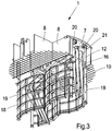
- FIG. 3 the first set and the second set of gripping tools 6, 19 are shown mounted with their respective drive mechanisms in the top part 3 of the container 1, obliquely from below.
- the top part 3 of the container 1 is partially covered by a mounting plate 7.
- the bearing housing 15 On the bottom side of the mounting plate 7 are mounted the bearing housing 15 with drive shafts 11 and drive mechanisms for the first set of gripping tools 6, as well as rotating mechanisms 20 and lifting mechanisms 12 for the second set of gripping tools 19.
- the mounting plate 7 is mounted on the top part 3 of the container 1 via the shell 5 and via vertically arranged supporting plates 8, preferably via welding and/or screw/bolt connection.
- the other part of the top part 3 of the container 1 is covered with a metal grille 10, mounted on the vertical supporting plates 8 and on the inner part of the shell 5 of the container 1.
- the function of the grille 8 is to ventilate overpressure and detonation gases from any detonation in the container 1.
- damming material 22 such as, for example, sandbags or liquid-filled plastics bags, Figs. 1 and 2 , to prevent large or medium-sized parts/fragments from the detonation from being scattered outside the container 1.
- a fastening device 17 is arranged on the top part 3 of the mounting plate 7 for suspension of the transport container 1 in a mobile crane, telpher, or for mounting on a control arm for manoeuvring the container 1 relative to a detonation-dangerous object 2.
- the fastening device 17 can be of the type hook, eyelet, screw, bolt or snap fastening.
- the transport container 1 After the transport container 1 has been manoeuvred, remote-controlled, into the correct position above the detonation-dangerous object 2, the transport container 1 is lowered down over the object 2, after which the first set and second set of gripping tools 6, 19 are maneuvered by remote control and coordinated such that the detonation-dangerous object can be gripped and loaded in the transport container 1 via the open bottom part 4, Figs. 1 , 2 and 4 .
- the raisable and lowerable inner part 14 can be used.
- the inner part 14 is locked, via a locking mechanism 16, in its lower position, Fig. 2 , after which the transport container 1 is lowered so that it ends up on the ground surface over the detonation-dangerous object 2, whereupon the gripping tools 6, 19 are manoeuvred such that the object 2 is gripped and loaded into the container 1 via the open bottom part 4.
- the fact that the range of the vertical gripping tools 6, in the vertical direction, is matched to the height of the container 1 when the inner part 14 is in its lower position allows the vertical gripping tools 6 to operate above the ground surface without being hampered by the ground.
- the inner part 14 is locked in the wholly or partially elevated position, which enables digging function and the possibility of accessing detonation-dangerous objects 2, for example mines, below the ground surface.
- the first set of gripping tools 6 are thus configured to access objects 2 which are located below the ground surface or objects 2 which are covered by, for example, stones/boulders or are otherwise concealed.
- the fork-like gripping tools 6 are exchanged for bucket-like or shovel-like collecting tools for enabling the collection of explosive objects 2 which are in liquid or powder form.
- an extra collecting container can also be arranged inside the transport container 1, for the storage of liquid or powdery objects 2 inside the container 1.
- the gripping tools 19, pivotable in the horizontal plane can also be supplemented by hinged plates or grilles on the bottom side of the gripping tools 19 for the collection of loosely connected objects 2 which are at risk of falling apart during the loading process.
Landscapes
- Engineering & Computer Science (AREA)
- General Engineering & Computer Science (AREA)
- Mechanical Engineering (AREA)
- Manipulator (AREA)
- Filling Or Discharging Of Gas Storage Vessels (AREA)
- Load-Engaging Elements For Cranes (AREA)
- Forklifts And Lifting Vehicles (AREA)
Description
- The present invention relates to a mobile detonation-proof transport container designed for easier handling and transport of detonation-dangerous objects, and a method for this same.
- The invention is specifically intended for the handling of detonation-dangerous objects of the type home-made explosive devices, shells or mines, but can also relate to the handling of chemically and/or bacteriologically dangerous objects which potentially constitute a threat to the environment.
- A growing problem in recent times has been the increasing use of explosive devices for terrorist purposes. The placement of explosive devices in towns and at airports, where many people are found, poses a high risk for the environment. In order to handle the problem, extensive intervention in the form of remote-controlled robots and detonation-proof containers is normally required, either by the explosive device being disabled directly on the spot, which calls for extensive barricades, or by the explosive device being placed in the detonation-proof container for transport to a safe place for subsequent disabling.
- The use of explosive devices/mines in conflict zones also constitutes a growing problem, firstly for the civilian population, but also for civilian staff and civilian equipment involved in humanitarian operations in the conflict zone.
-
US3820479, 23 February 1973 , Figure 6, discloses a mobile detonation-proof transport container, placed on a truck, for the handling and transport of detonation-dangerous objects to a safe place for subsequent destruction. The container is configured as an upright cylinder and is covered with a metal grille for pressure relief and for ventilation of detonation gases upon detonation. The container is also provided with an openable lid for the loading and unloading of detonation-dangerous objects. -
US4187758, 12 February 1980 ,Figures 3 and4 , also discloses a mobile detonation-proof transport container, placed on a truck, for the transport of explosive devices. The container, which is spherically configured and mounted on a pivotable arm, comprises a hatch which is opened and closed, under the influence of gravity, when the container is manoeuvred/rotated forwards and backwards. The loading and unloading of explosive devices in the container is facilitated by the hatch being opened and closed automatically during the manoeuvring of the container. - One problem with the said arrangements is, however, that the loading and unloading of detonation-dangerous objects in the container requires cooperation with some type of external manipulator or robot for loading and unloading, which is complicated and costly.
-
GR1003895 B1, 23 May 2002 Figure 1 , which can be regarded as a starting point for the present invention, discloses a mobile detonation proof container for loading and unloading of detonation-dangerous objects, wherein the container comprises individually manoeuvrable vertical gripping tools for the loading and unloading of detonation objects in the container tools for and a top part comprising a mounting plate on whose bottom side the individually manoeuvrable vertical gripping tools are mounted. - A main object of the present invention is a mobile detonation-proof transport container designed for easier handling in the loading and unloading of detonation-dangerous objects in the container.
- A further object of the present invention is a simplified method for use in the loading and unloading of detonation-dangerous objects in a mobile detonation-proof transport container.
- The said objects, as well as other objects which have not been enumerated here, are met in a satisfactory manner within the scope of that which is stated in the present independent patent claims. Embodiments of the invention are defined in the independent patent claims.
- Thus, according to the present invention, a mobile detonation-proof transport container, configured as an upright cylindrical container comprising a shell part and an open bottom part, suspended from a remote-controlled crane arm, for loading and unloading of detonation-dangerous objects in the container has been provided.
- The container comprises two sets of individually maneuverable remote-controlled gripping tools for the loading and unloading of detonation-dangerous objects in the container and a top part comprising a mounting plate on whose bottom side the two sets of individually maneuverable gripping tools are mounted, wherein the individually maneuverable gripping tools comprise, firstly, a first set of gripping tools for the maneuvering of detonation-dangerous objects in the first direction and, secondly, a second set of gripping tools for the maneuvering of detonation-dangerous objects in a second direction, different from the first direction, the second direction being in the horizontal plane, and wherein the second set of gripping tools comprise four rectangularly or squarely shaped grilles vertically arranged on vertical raisable and lowerable drive shafts inside the container, wherein the grilles are arranged rotatably in the horizontal plane.
- According to further aspects of the container according to the invention:
- the container comprises a raisable and lowerable inner part for controlling the distance between the first set of gripping tools and a detonation-dangerous object, depending on whether the object is located above or below the ground surface,
- the top part of the container comprises, firstly, a metal grille for the ventilation of overpressure and of detonation gases from a detonation in the container and, secondly, liquid-filled plastics bags for preventing the ejection of large and medium-sized parts to outside the container,
- the first set of gripping tools comprise two mutually opposing sets of fork-shaped gripping arms, in which each set of fork-shaped gripping arms is arranged rotatable on two horizontal drive shafts in a bearing housing in the top part of the container, wherein the gripping arms are arranged in a set via transverse stays,
- the first set of gripping tools comprise buckets for the collection of detonation-dangerous objects which are in liquid or powder form,
- the second set of pivotable gripping tools comprise hinged plates on the bottom side of the gripping tools for the collection of detonation-dangerous objects, which are loosely connected and are at risk of falling apart during the loading process.
- According to the present invention, a simplified Method for loading and unloading detonation-dangerous objects in a mobile detonation-proof transport container configured as an upright cylindrical container having an open bottom part comprising a mounting plate on whose bottom side two sets of individually maneuverable remote-controlled gripping tools are mounted and a top part comprising a mounting plate on whose bottom side the two sets of individually maneuverable gripping tools are mounted, and the individually maneuverable gripping tools comprise, firstly, a first set of gripping tools for the maneuvering of detonation-dangerous objects in a first direction and, secondly, a second set of gripping tools for the maneuvering of detonation-dangerous objects in a second direction, different from the first direction, the second direction being in the horizontal plane, and the second set of gripping tools comprise four rectangularly or squarely shaped grilles vertically arranged on vertical raisable and lowerable drive shafts inside the container, wherein the grilles are arranged rotatably in the horizontal plane.
- Characteristic of the method is that the loading and unloading of the detonation-dangerous objects in the container is effected via the maneuvering of the individually maneuverable gripping tools via the open bottom part of the container.
- The present invention now offers a simpler and safer method for handling detonation-dangerous objects in a mobile detonation-proof transport container, by virtue of the fact that gripping tools for the loading and unloading of objects in the container are arranged inside the container.
- That which is especially novel with the container according to the invention is the manner in which the loading and unloading of detonation-dangerous objects is done via the bottom opening in the container.
- The fact that gripping tools for loading and unloading are arranged inside the container and configured to, by remote control, grip objects which are located under the container on the ground surface or directly below the ground surface means that no further external manipulators or robots for loading and unloading objects in the container are required.
- From the above-stated, it will probably be clearly apparent that all activities associated with the handling of detonation-dangerous objects via the container according to the invention can be carried out without difficulty by remote control behind secure protection. The container according to the invention thus fulfils all the requirements which might be placed upon containers of the type referred to here.
- An important advantage of the container according to the invention is that, since the container comprises gripping tools for the loading and unloading of objects, accessibility, and thus the number of possible fields of application, is increased. The container with gripping tools is suspended from a crane arm and lowered down into poorly accessible spaces which are not normally accessible to containers in which external robots are required for the loading of objects.
- The fact that the gripping tools are also configured for digging function makes it possible to gather in and load objects located below the ground surface, for example mines.
- The gripping tools can also be configured to collect liquid or powdery explosive materials.
- A further advantage according to the invention is the absence of a hatch on the container, which simplifies the method used in the loading and unloading of objects.
- Further advantages and effects will emerge from a study and consideration of the following, detailed description of the invention, including one of its advantageous embodiments, the patent claims and the accompanying drawing figures.
- The invention has been defined in the following patent claims and will now be described only somewhat further in connection with the appended figures, in which:
-
Fig. 1 shows schematically a side projection of a mobile detonation-proof transport container comprising gripping tools and a raisable and lowerable inner part. -
Fig. 2 shows schematically a detonation-proof transport container according toFigure 1 , in which the raisable and lowerable inner part is in the lowered position. -
Fig. 3 shows schematically an oblique projection of a detonation-proof transport container according toFigure 1 , in which the arrangement of the first set and the second set of gripping tools can be seen. -
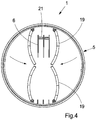
Fig. 4 shows schematically a projection from below of a detonation-proof transport container according toFigure 1 , in which interaction of the first set and second set of gripping tools can be seen. - In the various figures, corresponding parts have been given the same reference notations irrespective of the scales of the figures.
- The detonation-
proof transport container 1 according toFigs. 1 and2 is configured as an upright cylindrical container having acylindrical shell part 5, anopen bottom part 4 and a partially opentop part 3. Thecontainer 1 comprises a raisable and lowerableinner part 14, a first set ofgripping tools 6, and a second set ofgripping tools 19.Fig. 1 andFig. 2 show the raisable and lowerableinner part 14 in its upper and lower position respectively. - The first set of
gripping tools 6 comprise two mutually opposing sets of fork-shaped gripping arms, in which each set of fork-shaped gripping arms is arranged rotatably on two horizontally arrangeddrive shafts 11 in a bearinghousing 15 in thetop part 3 of thecontainer 1, which are arranged parallelly to one another viatransverse stays 21. As can further be seen fromFigs. 3 ,4 , the number of fork-shaped gripping arms on eachdrive shaft 11 is three, but can be more or fewer. Each one of thedrive shafts 11 is connected to a drive or rotating mechanism in thebearing housing 15. The drive mechanisms of thedrive shafts 11 can be of the chain or gearwheel type and are controlled, preferably, independently of each other. The drive mechanisms are driven, preferably, electrically via an electric motor, but can also be driven via compressed air or some other drive source. To thedrive mechanisms 6 are also connected one or more remote control mechanisms (not shown). - The second set of
gripping tools 19 comprise four rectangularly or squarely shaped grilles or plates arranged in pairs inside thecontainer 1, according toFig. 3 . - The
gripping tools 19, which, preferably, are slightly curved or arched for good gripping function, are rotatably or pivotably arranged on vertically arranged raisable andlowerable drive shafts 18 arranged parallelly to one another. The raisable andlowerable drive shafts 18 are connected, firstly, to acommon rotating mechanism 20 for synchronized rotation of the grille-like gripping tools 19 in the horizontal plane and, secondly, to acommon lifting mechanism 12 for synchronized lifting or lowering of thegripping tools 19. On the raisable andlowerable drive shafts 18 is also mounted the raisable and lowerableinner part 14. In an alternative embodiment, the raisable and lowerableinner part 14 is mounted on aseparate lifting mechanism 12 for independent lifting or lowering of theinner part 14. - In another alternative embodiment, the common
rotating mechanism 20 for thegripping tools 19 is replaced with individually operable rotating mechanisms (not shown). The commonrotating mechanism 20 and thelifting mechanism 12 are, preferably, electrically driven via electric motors, but can also be driven with compressed air or some other drive source. In addition, the rotatingmechanism 20 and thelifting mechanism 21 are connected to a remote control mechanism for remote-controlled manoeuvring of thegripping tools 19 and theinner part 14. - In
Fig. 3 , the first set and the second set ofgripping tools top part 3 of thecontainer 1, obliquely from below. As can be seen fromFig. 3 , thetop part 3 of thecontainer 1 is partially covered by a mountingplate 7. On the bottom side of the mountingplate 7 are mounted the bearinghousing 15 withdrive shafts 11 and drive mechanisms for the first set ofgripping tools 6, as well asrotating mechanisms 20 andlifting mechanisms 12 for the second set ofgripping tools 19. - The mounting
plate 7 is mounted on thetop part 3 of thecontainer 1 via theshell 5 and via vertically arranged supportingplates 8, preferably via welding and/or screw/bolt connection. - The other part of the
top part 3 of thecontainer 1 is covered with ametal grille 10, mounted on the vertical supportingplates 8 and on the inner part of theshell 5 of thecontainer 1. The function of thegrille 8 is to ventilate overpressure and detonation gases from any detonation in thecontainer 1. On parts of thegrille 10 is also arranged dammingmaterial 22, such as, for example, sandbags or liquid-filled plastics bags,Figs. 1 and2 , to prevent large or medium-sized parts/fragments from the detonation from being scattered outside thecontainer 1. - As can further be seen from
Fig. 1 andFig. 2 , afastening device 17 is arranged on thetop part 3 of the mountingplate 7 for suspension of thetransport container 1 in a mobile crane, telpher, or for mounting on a control arm for manoeuvring thecontainer 1 relative to a detonation-dangerous object 2. Thefastening device 17 can be of the type hook, eyelet, screw, bolt or snap fastening. - After the
transport container 1 has been manoeuvred, remote-controlled, into the correct position above the detonation-dangerous object 2, thetransport container 1 is lowered down over theobject 2, after which the first set and second set ofgripping tools transport container 1 via the openbottom part 4,Figs. 1 ,2 and4 . - Depending on whether the detonation-
dangerous object 2 is located visibly directly on the ground or below the ground surface, the raisable and lowerableinner part 14 can be used. - If the
object 2 is located on the ground surface, theinner part 14 is locked, via alocking mechanism 16, in its lower position,Fig. 2 , after which thetransport container 1 is lowered so that it ends up on the ground surface over the detonation-dangerous object 2, whereupon thegripping tools object 2 is gripped and loaded into thecontainer 1 via the openbottom part 4. The fact that the range of the verticalgripping tools 6, in the vertical direction, is matched to the height of thecontainer 1 when theinner part 14 is in its lower position allows the verticalgripping tools 6 to operate above the ground surface without being hampered by the ground. - If the
object 2 is located below the ground surface,Fig. 1 , theinner part 14 is locked in the wholly or partially elevated position, which enables digging function and the possibility of accessing detonation-dangerous objects 2, for example mines, below the ground surface. The first set ofgripping tools 6 are thus configured to accessobjects 2 which are located below the ground surface or objects 2 which are covered by, for example, stones/boulders or are otherwise concealed. - In a further embodiment (not shown), the fork-like
gripping tools 6 are exchanged for bucket-like or shovel-like collecting tools for enabling the collection ofexplosive objects 2 which are in liquid or powder form. In the said embodiment comprising bucket-like or shovel-like collecting tools, an extra collecting container can also be arranged inside thetransport container 1, for the storage of liquid orpowdery objects 2 inside thecontainer 1. - In a further alternative embodiment, the
gripping tools 19, pivotable in the horizontal plane, can also be supplemented by hinged plates or grilles on the bottom side of thegripping tools 19 for the collection of loosely connectedobjects 2 which are at risk of falling apart during the loading process.
Claims (7)
- Mobile detonation-proof transport container (1), configured as an upright cylindrical container comprising a shell part (2) and an open bottom part (4), suspended from a remote-controlled crane arm, for loading and unloading of detonation-dangerous objects (2) in the container (1), wherein the container (1) comprise two sets of individually maneuverable remote-controlled gripping tools (6, 19) for the loading and unloading of detonation-dangerous objects (2) in the container (1) and a top part (3) comprising a mounting plate (7) on whose bottom side the two sets of individually maneuverable gripping tools (6, 19) are mounted, wherein the individually maneuverable gripping tools (6, 19) comprise, firstly, a first set of gripping tools (6) for the maneuvering of detonation-dangerous objects (2) in a first direction and, secondly, a second set of gripping tools (19) for the maneuvering of detonation-dangerous objects (2) in a second direction different from the first direction, the second direction being in the horizontal plane, and wherein the second set of gripping tools (19) comprise four rectangularly or squarely shaped grilles vertically arranged on vertical raisable and lowerable drive shafts (18) inside the container (1), wherein the grilles are arranged rotatably in the horizontal plane.
- Mobile detonation-proof transport container (1) according to Claim 1, wherein the container (1) also comprises a raisable and lowerable inner part (14) for controlling the distance between the first set of gripping tools (6) and a detonation-dangerous object (2), depending on whether the object (2) is located above or below the ground surface.
- Mobile detonation-proof transport container (1) according to Claim 1, wherein the top part (3) of the container (1) comprises, firstly, a metal grille (10) for the ventilation of overpressure and of detonation gases from a detonation in the container (1) and, secondly, liquid-filled plastics bags (22) for preventing the ejection of large and medium-sized parts to outside the container (1).
- Mobile detonation-proof transport container (1) according to Claim 1, wherein the first set of gripping tools (6) comprise two mutually opposing sets of fork-shaped gripping arms, in which each set of fork-shaped gripping arms is arranged rotatably on a horizontal drive shaft (11) in a bearing housing (15) in the top part (3) of the container (1), wherein the gripping arms in a set are arranged parallelly to one another via transverse stays (21).
- Mobile detonation-proof transport container (1) according to Claim 1, wherein the first set of gripping tools (6) comprise buckets for the collection of detonation-dangerous objects (2) which are in liquid or powder form.
- Mobile detonation-proof transport container (1) according to Claim 1, wherein the second set of pivotable gripping tools (19) comprise hinged plates on the bottom side of the gripping tools (19) for the collection of detonation-dangerous objects (2), which are loosely connected and are at risk of falling apart during the loading process.
- Method for loading and unloading detonation-dangerous objects (2) in a mobile detonation-proof transport container (1) configured as an upright cylindrical container having an open bottom part (4) comprising a mounting plate (7) on whose bottom side two sets of individually maneuverable remote-controlled gripping tools (6, 19) are mounted and a top part (3) comprising a mounting plate (7) on whose bottom side the two sets of individually maneuverable gripping tools (6, 19) are mounted, wherein the individually maneuverable gripping tools (6, 19) comprise, firstly, a first set of gripping tools (6) for the maneuvering of detonation-dangerous objects (2) in a first direction and, secondly, a second set of gripping tools (19) for the maneuvering of detonation-dangerous objects (2) in a second direction, different from the first direction, the second direction being in the horizontal plane, and wherein the second set of gripping tools (19) comprise four rectangularly or squarely shaped grilles vertically arranged on vertical raisable and lowerable drive shafts (18) inside the container (1), wherein the grilles are arranged rotatably in the horizontal plane, wherein the loading and unloading of the detonation-dangerous objects (2) in the container (1) is effected via the maneuvering of the individually maneuverable gripping (6, 19)tools via the open bottom part (4) of the container (1).
Applications Claiming Priority (2)
| Application Number | Priority Date | Filing Date | Title |
|---|---|---|---|
| SE1100207A SE535715C2 (en) | 2011-03-22 | 2011-03-22 | Mobile transport container for handling detonated dangerous objects and procedures |
| PCT/SE2012/000038 WO2012128691A1 (en) | 2011-03-22 | 2012-03-21 | Mobile transport container for handling of detonation-dangerous objects and method for this same |
Publications (3)
| Publication Number | Publication Date |
|---|---|
| EP2689209A1 EP2689209A1 (en) | 2014-01-29 |
| EP2689209A4 EP2689209A4 (en) | 2014-08-13 |
| EP2689209B1 true EP2689209B1 (en) | 2017-03-08 |
Family
ID=46879603
Family Applications (1)
| Application Number | Title | Priority Date | Filing Date |
|---|---|---|---|
| EP12760510.3A Active EP2689209B1 (en) | 2011-03-22 | 2012-03-21 | Mobile transport container for handling of detonation-dangerous objects and method for this same |
Country Status (6)
| Country | Link |
|---|---|
| US (1) | US9004558B2 (en) |
| EP (1) | EP2689209B1 (en) |
| JP (1) | JP5748899B2 (en) |
| CN (1) | CN103649671B (en) |
| SE (1) | SE535715C2 (en) |
| WO (1) | WO2012128691A1 (en) |
Families Citing this family (6)
| Publication number | Priority date | Publication date | Assignee | Title |
|---|---|---|---|---|
| JP6270595B2 (en) * | 2014-04-01 | 2018-01-31 | 鈴鹿エンヂニヤリング株式会社 | Method and apparatus for lifting and conveying bale rubber |
| JP6851940B2 (en) * | 2017-09-04 | 2021-03-31 | 昭和飛行機工業株式会社 | Suspicious object processing device |
| CN111547376B (en) * | 2020-05-15 | 2024-06-25 | 北京中储能能源设备有限公司 | Nonmetal barrier explosion-proof unit |
| CN113175856B (en) * | 2021-03-31 | 2022-10-18 | 湖南艾尔防务技术有限公司 | Intelligent mobile type explosion-proof barrel |
| CN116443718B (en) * | 2023-06-16 | 2023-08-25 | 河南省天桥重型机械有限公司 | Explosion-proof single-beam crane for coal |
| KR20250115718A (en) * | 2024-01-24 | 2025-07-31 | 한국가스공사 | Monitoring system for vehicle for transporting hazardous goods |
Family Cites Families (23)
| Publication number | Priority date | Publication date | Assignee | Title |
|---|---|---|---|---|
| US1990673A (en) * | 1934-01-08 | 1935-02-12 | Cullen Friestedt Company | Grapple |
| US2315800A (en) | 1942-06-09 | 1943-04-06 | Thomas W Rochester | Apparatus for handling explosives |
| US2355086A (en) * | 1943-10-27 | 1944-08-08 | Walter B Lang | Marine salvage device |
| US3721201A (en) | 1971-09-30 | 1973-03-20 | W Boller | Bomb recovery and shield apparatus |
| US3820479A (en) | 1973-02-23 | 1974-06-28 | Fmc Corp | Mobile container for safely handling explosives |
| US3929366A (en) * | 1974-08-21 | 1975-12-30 | John J Keverline | Cotton loader |
| US4187758A (en) | 1978-01-03 | 1980-02-12 | The United States Of America As Represented By The Secretary Of The Army | Bomb container with gravity-closed internal door |
| US4669940A (en) * | 1984-05-22 | 1987-06-02 | Emco Industries, Inc. | Apparatus for handling refuse containers and the like |
| US5209537A (en) * | 1991-07-10 | 1993-05-11 | The Heil Co. | Gripping apparatus for omnifarious containers |
| AU634439B1 (en) * | 1991-07-24 | 1993-02-18 | Anthony Paul Ahrens | Gripping apparatus |
| US5291819A (en) * | 1992-09-29 | 1994-03-08 | Hambric Harry N | Battlefield debris clearing apparatus |
| US5443294A (en) * | 1993-09-22 | 1995-08-22 | Hawco Manufacturing Co. | Single-line clamshell bucket |
| US5570920A (en) * | 1994-02-16 | 1996-11-05 | Northeastern University | Robot arm end effector |
| US5639201A (en) * | 1994-02-25 | 1997-06-17 | Curotto; John D. | Materials collecting apparatus |
| JP3907280B2 (en) * | 1997-08-26 | 2007-04-18 | 株式会社アイ・エイチ・アイ・エアロスペース | Landmine disposal method and landmine disposal device |
| US5975168A (en) * | 1998-09-11 | 1999-11-02 | Caterpillar Commercial Sarl | Device and method for trimming a tree |
| GR1003895B (en) * | 2001-05-07 | 2002-05-23 | Soukos Robots Αβεε | Robot for collecting and transporting hazardous luggage |
| GB0405859D0 (en) * | 2004-03-16 | 2004-04-21 | Cintec Int Ltd | Improvements in and relating to blast mitigation structures |
| US7347657B2 (en) * | 2004-11-03 | 2008-03-25 | Larry Brunn | Simplified refuse collection apparatus |
| GB0708571D0 (en) * | 2007-05-03 | 2007-06-13 | Aew Delford Systems Ltd | Pick and place gripper device |
| CN201255611Y (en) * | 2008-07-10 | 2009-06-10 | 靳洪伟 | Door construction for explosion prevention spherical tank |
| KR100945083B1 (en) * | 2009-04-01 | 2010-03-05 | 강토중공업(주) | Multi-grapple for excavator |
| US8677876B2 (en) * | 2011-07-16 | 2014-03-25 | Kevin Mark Diaz | 4D simultaneous robotic containment with recoil |
-
2011
- 2011-03-22 SE SE1100207A patent/SE535715C2/en unknown
-
2012
- 2012-03-21 EP EP12760510.3A patent/EP2689209B1/en active Active
- 2012-03-21 US US14/006,543 patent/US9004558B2/en active Active
- 2012-03-21 WO PCT/SE2012/000038 patent/WO2012128691A1/en not_active Ceased
- 2012-03-21 JP JP2014501036A patent/JP5748899B2/en active Active
- 2012-03-21 CN CN201280014304.2A patent/CN103649671B/en active Active
Also Published As
| Publication number | Publication date |
|---|---|
| EP2689209A1 (en) | 2014-01-29 |
| WO2012128691A1 (en) | 2012-09-27 |
| CN103649671A (en) | 2014-03-19 |
| CN103649671B (en) | 2016-03-16 |
| US20140083899A1 (en) | 2014-03-27 |
| SE1100207A1 (en) | 2012-09-23 |
| EP2689209A4 (en) | 2014-08-13 |
| US9004558B2 (en) | 2015-04-14 |
| JP5748899B2 (en) | 2015-07-15 |
| JP2014514526A (en) | 2014-06-19 |
| SE535715C2 (en) | 2012-11-20 |
Similar Documents
| Publication | Publication Date | Title |
|---|---|---|
| US9004558B2 (en) | Mobile transport container for handling of detonation-dangerous objects and method for this same | |
| US10697737B2 (en) | Armouring system for self-propelled work machines | |
| EP4069608B1 (en) | Service vehicle for automated storage system | |
| EP2558812B1 (en) | An operation platform | |
| US9653189B2 (en) | Canister transfer system with independent traveling shielded bell | |
| JP6963922B2 (en) | Radioactive material carry-out device, radioactive material carry-in device, radioactive material transport system and its method | |
| CN205111837U (en) | Explosive ordnance disposal mechanical hand | |
| CN109748220A (en) | Automatic Kaifeng lid arrangement | |
| CN109368491A (en) | A kind of grab bucket for bridge type ship unloader | |
| CN209038554U (en) | Oil drum handling module applied to explosive-removal robot | |
| CN216783353U (en) | Emergency comprehensive disposal vehicle for dangerous explosive | |
| CN209778073U (en) | Unexplosive bomb explosive-removal grab bucket | |
| KR102762950B1 (en) | Material airlift system and material airlift method | |
| CN215037532U (en) | Robot for removing explosive | |
| CN117503499A (en) | Rescue unmanned vehicle | |
| CN210733954U (en) | Emergency rescue vehicle | |
| RU102329U1 (en) | Demining support complex and explosion-proof container for its implementation | |
| RU2462376C2 (en) | Mine clearing complex and explosion-proof container to this end | |
| JP2016141374A (en) | On-vehicle unseasoned tea leaf storage device | |
| KR102919603B1 (en) | Unmanned Air Vehicle for Collecting Objects Mounted on Balloon | |
| WO2018069903A1 (en) | Property surveillance and security system | |
| JP2006258353A (en) | Explosive loaded car | |
| RU2350493C1 (en) | Transporting and docking facility | |
| JP6670149B2 (en) | Transport device and storage facility equipped with the same | |
| CN208215364U (en) | A kind of small anti-explosion robot based on electric pushrod |
Legal Events
| Date | Code | Title | Description |
|---|---|---|---|
| PUAI | Public reference made under article 153(3) epc to a published international application that has entered the european phase |
Free format text: ORIGINAL CODE: 0009012 |
|
| 17P | Request for examination filed |
Effective date: 20131014 |
|
| AK | Designated contracting states |
Kind code of ref document: A1 Designated state(s): AL AT BE BG CH CY CZ DE DK EE ES FI FR GB GR HR HU IE IS IT LI LT LU LV MC MK MT NL NO PL PT RO RS SE SI SK SM TR |
|
| DAX | Request for extension of the european patent (deleted) | ||
| A4 | Supplementary search report drawn up and despatched |
Effective date: 20140716 |
|
| RIC1 | Information provided on ipc code assigned before grant |
Ipc: F41H 11/28 20110101AFI20140710BHEP Ipc: F42D 5/045 20060101ALI20140710BHEP Ipc: B66C 3/04 20060101ALI20140710BHEP Ipc: F42B 39/14 20060101ALI20140710BHEP |
|
| 17Q | First examination report despatched |
Effective date: 20160422 |
|
| REG | Reference to a national code |
Ref country code: DE Ref legal event code: R079 Ref document number: 602012029594 Country of ref document: DE Free format text: PREVIOUS MAIN CLASS: F41H0011120000 Ipc: F41H0011280000 |
|
| RIC1 | Information provided on ipc code assigned before grant |
Ipc: F41H 11/28 20110101AFI20160831BHEP Ipc: F42D 5/045 20060101ALI20160831BHEP Ipc: B66C 3/16 20060101ALI20160831BHEP Ipc: B66C 3/18 20060101ALI20160831BHEP Ipc: F42B 39/14 20060101ALI20160831BHEP Ipc: B66C 3/04 20060101ALI20160831BHEP |
|
| GRAP | Despatch of communication of intention to grant a patent |
Free format text: ORIGINAL CODE: EPIDOSNIGR1 |
|
| INTG | Intention to grant announced |
Effective date: 20161013 |
|
| GRAS | Grant fee paid |
Free format text: ORIGINAL CODE: EPIDOSNIGR3 |
|
| GRAA | (expected) grant |
Free format text: ORIGINAL CODE: 0009210 |
|
| AK | Designated contracting states |
Kind code of ref document: B1 Designated state(s): AL AT BE BG CH CY CZ DE DK EE ES FI FR GB GR HR HU IE IS IT LI LT LU LV MC MK MT NL NO PL PT RO RS SE SI SK SM TR |
|
| REG | Reference to a national code |
Ref country code: GB Ref legal event code: FG4D |
|
| REG | Reference to a national code |
Ref country code: CH Ref legal event code: EP Ref country code: AT Ref legal event code: REF Ref document number: 873910 Country of ref document: AT Kind code of ref document: T Effective date: 20170315 |
|
| REG | Reference to a national code |
Ref country code: FR Ref legal event code: PLFP Year of fee payment: 6 |
|
| REG | Reference to a national code |
Ref country code: IE Ref legal event code: FG4D |
|
| REG | Reference to a national code |
Ref country code: DE Ref legal event code: R096 Ref document number: 602012029594 Country of ref document: DE |
|
| REG | Reference to a national code |
Ref country code: LT Ref legal event code: MG4D |
|
| REG | Reference to a national code |
Ref country code: NL Ref legal event code: MP Effective date: 20170308 |
|
| PG25 | Lapsed in a contracting state [announced via postgrant information from national office to epo] |
Ref country code: NO Free format text: LAPSE BECAUSE OF FAILURE TO SUBMIT A TRANSLATION OF THE DESCRIPTION OR TO PAY THE FEE WITHIN THE PRESCRIBED TIME-LIMIT Effective date: 20170608 Ref country code: LT Free format text: LAPSE BECAUSE OF FAILURE TO SUBMIT A TRANSLATION OF THE DESCRIPTION OR TO PAY THE FEE WITHIN THE PRESCRIBED TIME-LIMIT Effective date: 20170308 Ref country code: GR Free format text: LAPSE BECAUSE OF FAILURE TO SUBMIT A TRANSLATION OF THE DESCRIPTION OR TO PAY THE FEE WITHIN THE PRESCRIBED TIME-LIMIT Effective date: 20170609 Ref country code: FI Free format text: LAPSE BECAUSE OF FAILURE TO SUBMIT A TRANSLATION OF THE DESCRIPTION OR TO PAY THE FEE WITHIN THE PRESCRIBED TIME-LIMIT Effective date: 20170308 Ref country code: HR Free format text: LAPSE BECAUSE OF FAILURE TO SUBMIT A TRANSLATION OF THE DESCRIPTION OR TO PAY THE FEE WITHIN THE PRESCRIBED TIME-LIMIT Effective date: 20170308 |
|
| REG | Reference to a national code |
Ref country code: AT Ref legal event code: MK05 Ref document number: 873910 Country of ref document: AT Kind code of ref document: T Effective date: 20170308 |
|
| PG25 | Lapsed in a contracting state [announced via postgrant information from national office to epo] |
Ref country code: LV Free format text: LAPSE BECAUSE OF FAILURE TO SUBMIT A TRANSLATION OF THE DESCRIPTION OR TO PAY THE FEE WITHIN THE PRESCRIBED TIME-LIMIT Effective date: 20170308 Ref country code: BG Free format text: LAPSE BECAUSE OF FAILURE TO SUBMIT A TRANSLATION OF THE DESCRIPTION OR TO PAY THE FEE WITHIN THE PRESCRIBED TIME-LIMIT Effective date: 20170608 Ref country code: SE Free format text: LAPSE BECAUSE OF FAILURE TO SUBMIT A TRANSLATION OF THE DESCRIPTION OR TO PAY THE FEE WITHIN THE PRESCRIBED TIME-LIMIT Effective date: 20170308 Ref country code: RS Free format text: LAPSE BECAUSE OF FAILURE TO SUBMIT A TRANSLATION OF THE DESCRIPTION OR TO PAY THE FEE WITHIN THE PRESCRIBED TIME-LIMIT Effective date: 20170308 Ref country code: ES Free format text: LAPSE BECAUSE OF FAILURE TO SUBMIT A TRANSLATION OF THE DESCRIPTION OR TO PAY THE FEE WITHIN THE PRESCRIBED TIME-LIMIT Effective date: 20170308 |
|
| PG25 | Lapsed in a contracting state [announced via postgrant information from national office to epo] |
Ref country code: NL Free format text: LAPSE BECAUSE OF FAILURE TO SUBMIT A TRANSLATION OF THE DESCRIPTION OR TO PAY THE FEE WITHIN THE PRESCRIBED TIME-LIMIT Effective date: 20170308 |
|
| PG25 | Lapsed in a contracting state [announced via postgrant information from national office to epo] |
Ref country code: AT Free format text: LAPSE BECAUSE OF FAILURE TO SUBMIT A TRANSLATION OF THE DESCRIPTION OR TO PAY THE FEE WITHIN THE PRESCRIBED TIME-LIMIT Effective date: 20170308 Ref country code: SK Free format text: LAPSE BECAUSE OF FAILURE TO SUBMIT A TRANSLATION OF THE DESCRIPTION OR TO PAY THE FEE WITHIN THE PRESCRIBED TIME-LIMIT Effective date: 20170308 Ref country code: RO Free format text: LAPSE BECAUSE OF FAILURE TO SUBMIT A TRANSLATION OF THE DESCRIPTION OR TO PAY THE FEE WITHIN THE PRESCRIBED TIME-LIMIT Effective date: 20170308 Ref country code: CZ Free format text: LAPSE BECAUSE OF FAILURE TO SUBMIT A TRANSLATION OF THE DESCRIPTION OR TO PAY THE FEE WITHIN THE PRESCRIBED TIME-LIMIT Effective date: 20170308 Ref country code: IT Free format text: LAPSE BECAUSE OF FAILURE TO SUBMIT A TRANSLATION OF THE DESCRIPTION OR TO PAY THE FEE WITHIN THE PRESCRIBED TIME-LIMIT Effective date: 20170308 Ref country code: EE Free format text: LAPSE BECAUSE OF FAILURE TO SUBMIT A TRANSLATION OF THE DESCRIPTION OR TO PAY THE FEE WITHIN THE PRESCRIBED TIME-LIMIT Effective date: 20170308 |
|
| REG | Reference to a national code |
Ref country code: CH Ref legal event code: PL |
|
| PG25 | Lapsed in a contracting state [announced via postgrant information from national office to epo] |
Ref country code: IS Free format text: LAPSE BECAUSE OF FAILURE TO SUBMIT A TRANSLATION OF THE DESCRIPTION OR TO PAY THE FEE WITHIN THE PRESCRIBED TIME-LIMIT Effective date: 20170708 Ref country code: PL Free format text: LAPSE BECAUSE OF FAILURE TO SUBMIT A TRANSLATION OF THE DESCRIPTION OR TO PAY THE FEE WITHIN THE PRESCRIBED TIME-LIMIT Effective date: 20170308 Ref country code: SM Free format text: LAPSE BECAUSE OF FAILURE TO SUBMIT A TRANSLATION OF THE DESCRIPTION OR TO PAY THE FEE WITHIN THE PRESCRIBED TIME-LIMIT Effective date: 20170308 Ref country code: PT Free format text: LAPSE BECAUSE OF FAILURE TO SUBMIT A TRANSLATION OF THE DESCRIPTION OR TO PAY THE FEE WITHIN THE PRESCRIBED TIME-LIMIT Effective date: 20170710 |
|
| REG | Reference to a national code |
Ref country code: DE Ref legal event code: R097 Ref document number: 602012029594 Country of ref document: DE |
|
| REG | Reference to a national code |
Ref country code: IE Ref legal event code: MM4A |
|
| PLBE | No opposition filed within time limit |
Free format text: ORIGINAL CODE: 0009261 |
|
| STAA | Information on the status of an ep patent application or granted ep patent |
Free format text: STATUS: NO OPPOSITION FILED WITHIN TIME LIMIT |
|
| PG25 | Lapsed in a contracting state [announced via postgrant information from national office to epo] |
Ref country code: MC Free format text: LAPSE BECAUSE OF FAILURE TO SUBMIT A TRANSLATION OF THE DESCRIPTION OR TO PAY THE FEE WITHIN THE PRESCRIBED TIME-LIMIT Effective date: 20170308 Ref country code: LU Free format text: LAPSE BECAUSE OF NON-PAYMENT OF DUE FEES Effective date: 20170321 Ref country code: DK Free format text: LAPSE BECAUSE OF FAILURE TO SUBMIT A TRANSLATION OF THE DESCRIPTION OR TO PAY THE FEE WITHIN THE PRESCRIBED TIME-LIMIT Effective date: 20170308 |
|
| 26N | No opposition filed |
Effective date: 20171211 |
|
| PG25 | Lapsed in a contracting state [announced via postgrant information from national office to epo] |
Ref country code: CH Free format text: LAPSE BECAUSE OF NON-PAYMENT OF DUE FEES Effective date: 20170331 Ref country code: SI Free format text: LAPSE BECAUSE OF FAILURE TO SUBMIT A TRANSLATION OF THE DESCRIPTION OR TO PAY THE FEE WITHIN THE PRESCRIBED TIME-LIMIT Effective date: 20170308 Ref country code: LI Free format text: LAPSE BECAUSE OF NON-PAYMENT OF DUE FEES Effective date: 20170331 Ref country code: IE Free format text: LAPSE BECAUSE OF NON-PAYMENT OF DUE FEES Effective date: 20170321 |
|
| REG | Reference to a national code |
Ref country code: BE Ref legal event code: MM Effective date: 20170331 |
|
| REG | Reference to a national code |
Ref country code: FR Ref legal event code: PLFP Year of fee payment: 7 |
|
| PG25 | Lapsed in a contracting state [announced via postgrant information from national office to epo] |
Ref country code: BE Free format text: LAPSE BECAUSE OF NON-PAYMENT OF DUE FEES Effective date: 20170331 |
|
| PG25 | Lapsed in a contracting state [announced via postgrant information from national office to epo] |
Ref country code: MT Free format text: LAPSE BECAUSE OF NON-PAYMENT OF DUE FEES Effective date: 20170321 |
|
| PG25 | Lapsed in a contracting state [announced via postgrant information from national office to epo] |
Ref country code: HU Free format text: LAPSE BECAUSE OF FAILURE TO SUBMIT A TRANSLATION OF THE DESCRIPTION OR TO PAY THE FEE WITHIN THE PRESCRIBED TIME-LIMIT; INVALID AB INITIO Effective date: 20120321 |
|
| PG25 | Lapsed in a contracting state [announced via postgrant information from national office to epo] |
Ref country code: CY Free format text: LAPSE BECAUSE OF NON-PAYMENT OF DUE FEES Effective date: 20170308 |
|
| PG25 | Lapsed in a contracting state [announced via postgrant information from national office to epo] |
Ref country code: MK Free format text: LAPSE BECAUSE OF FAILURE TO SUBMIT A TRANSLATION OF THE DESCRIPTION OR TO PAY THE FEE WITHIN THE PRESCRIBED TIME-LIMIT Effective date: 20170308 |
|
| PG25 | Lapsed in a contracting state [announced via postgrant information from national office to epo] |
Ref country code: TR Free format text: LAPSE BECAUSE OF FAILURE TO SUBMIT A TRANSLATION OF THE DESCRIPTION OR TO PAY THE FEE WITHIN THE PRESCRIBED TIME-LIMIT Effective date: 20170308 |
|
| PG25 | Lapsed in a contracting state [announced via postgrant information from national office to epo] |
Ref country code: AL Free format text: LAPSE BECAUSE OF FAILURE TO SUBMIT A TRANSLATION OF THE DESCRIPTION OR TO PAY THE FEE WITHIN THE PRESCRIBED TIME-LIMIT Effective date: 20170308 |
|
| REG | Reference to a national code |
Ref country code: DE Ref legal event code: R081 Ref document number: 602012029594 Country of ref document: DE Owner name: DYNASAFE DEMIL SYSTEMS AB, SE Free format text: FORMER OWNER: DYNASAFE INTERNATIONAL AB, MALMOE, SE Ref country code: DE Ref legal event code: R081 Ref document number: 602012029594 Country of ref document: DE Owner name: DYNASAFE DEMIL SYSTEMS AB, SE Free format text: FORMER OWNER: DYNASAFE INTERNATIONAL AB, STOCKHOLM, SE |
|
| REG | Reference to a national code |
Ref country code: GB Ref legal event code: 732E Free format text: REGISTERED BETWEEN 20220203 AND 20220209 |
|
| PGFP | Annual fee paid to national office [announced via postgrant information from national office to epo] |
Ref country code: GB Payment date: 20260317 Year of fee payment: 15 |
|
| PGFP | Annual fee paid to national office [announced via postgrant information from national office to epo] |
Ref country code: DE Payment date: 20260318 Year of fee payment: 15 |
|
| PGFP | Annual fee paid to national office [announced via postgrant information from national office to epo] |
Ref country code: FR Payment date: 20260317 Year of fee payment: 15 |