EP2688767B1 - Load-strapping device - Google Patents
Load-strapping device Download PDFInfo
- Publication number
- EP2688767B1 EP2688767B1 EP12711749.7A EP12711749A EP2688767B1 EP 2688767 B1 EP2688767 B1 EP 2688767B1 EP 12711749 A EP12711749 A EP 12711749A EP 2688767 B1 EP2688767 B1 EP 2688767B1
- Authority
- EP
- European Patent Office
- Prior art keywords
- spindle
- load
- strapping device
- strap
- parts
- Prior art date
- Legal status (The legal status is an assumption and is not a legal conclusion. Google has not performed a legal analysis and makes no representation as to the accuracy of the status listed.)
- Active
Links
Images



Classifications
-
- B—PERFORMING OPERATIONS; TRANSPORTING
- B60—VEHICLES IN GENERAL
- B60P—VEHICLES ADAPTED FOR LOAD TRANSPORTATION OR TO TRANSPORT, TO CARRY, OR TO COMPRISE SPECIAL LOADS OR OBJECTS
- B60P7/00—Securing or covering of load on vehicles
- B60P7/06—Securing of load
-
- B—PERFORMING OPERATIONS; TRANSPORTING
- B60—VEHICLES IN GENERAL
- B60P—VEHICLES ADAPTED FOR LOAD TRANSPORTATION OR TO TRANSPORT, TO CARRY, OR TO COMPRISE SPECIAL LOADS OR OBJECTS
- B60P7/00—Securing or covering of load on vehicles
- B60P7/06—Securing of load
- B60P7/08—Securing to the vehicle floor or sides
- B60P7/0823—Straps; Tighteners
- B60P7/083—Tensioning by repetetive movement of an actuating member
-
- Y—GENERAL TAGGING OF NEW TECHNOLOGICAL DEVELOPMENTS; GENERAL TAGGING OF CROSS-SECTIONAL TECHNOLOGIES SPANNING OVER SEVERAL SECTIONS OF THE IPC; TECHNICAL SUBJECTS COVERED BY FORMER USPC CROSS-REFERENCE ART COLLECTIONS [XRACs] AND DIGESTS
- Y10—TECHNICAL SUBJECTS COVERED BY FORMER USPC
- Y10T—TECHNICAL SUBJECTS COVERED BY FORMER US CLASSIFICATION
- Y10T24/00—Buckles, buttons, clasps, etc.
- Y10T24/21—Strap tighteners
- Y10T24/2175—Cargo tie down
Definitions
- the invention concerns a load-strapping device of the kind used for securing load to a vehicle, particularly trailers and lorries.
- the device is provided for joining and tensioning straps holding the load onto a platform or other load-carrying base.
- Prior art load-strapping devices are provided with a spindle extending between flanges of mutually pivoting frame parts of the device.
- a free end of a strap is passed through a slot in the spindle, and by a pawl-and-ratchet mechanism provided at the joint, the spindle is rotated in one direction, thus winding the strap around itself when the frame parts are repeatedly pivoted in opposite directions.
- Releasing the strap occurs by releasing the ratchet wheel by pulling two arresting pawls, one in each frame parts, against spring bias, allowing the spindle to rotate backwards and unwind the strap. After that, the free end of the strap can be pulled out from the slot.
- US 2008/0244883 A1 discloses a strapping device where the spindle itself is a two-part design. A first part of the spindle can be moved relatively to a second part of the spindle in order to engage and/or release a strap between the parts of the spindle. The movement between the spindle parts for engaging and releasing the strap is lateral such that one spindle part is slid in parallel with the other part of the spindle, thus exposing a space where the strap is to be located. Thereby it is possible to place the strap in the exposed space without having to use and pull the end of the strap through a slot in the spindle. The slot is established after positioning the strap by sliding the other part of the spindle back into operating or closed position. Releasing the strap after unwinding is provided by reversing the movement of the movable part of the spindle. A similar design is disclosed in WO 2007/113373 .
- WO 2006/001714 discloses a strapping device with a bifurcated spindle.
- the spindle is provided with two parallel arms joined by a bend. In the mounted condition, the parallel arms form a slot in the spindle.
- the spindle can be inserted and pulled out laterally in the joint between the movable parts. In this way, the strap can be fitted and removed without taking the free end of the strap and pull it through the slot. Releasing can be done by drawing the spindle laterally, thus allowing the windings of the strap to slide off the spindle.
- a further device is known from US 2010/205790 , on which the preamble of claim 1 is based.
- a load-strapping device including two frame parts connected by a pivotable joint, where one frame part is attached to a strap, where the joint between the pivotable parts is provided with a spindle extending between parallel flanges of the frame parts, the pivotable joint between the pivotable parts provided at opposite ends of the spindle with a pawl-and-ratchet mechanism which provides one-way rotation of the spindle when the pivotable basic parts are pivoted repeatedly in opposing directions, the spindle itself being a two-part design, where a first part of the spindle can be moved relatively to a second part of the spindle in order to engage and/or release a strap between the parts of the spindle.
- a similar device is disclosed in FR 2915856 .
- the strapping device is peculiar in that the first part of the spindle is suspended pivotably about a pivot axis extending through one end of the spindle and substantially at right angles to the spindle so that the first part can be pivoted between a closed position defined as substantially in parallel with the second part of the spindle and so that a plane containing the pivot axis extends longitudinally through the first and second parts of the spindle, and an open position defined as the first part being pivoted so as to form an angle with the plane.
- the first part of the spindle When mounting the strap, the first part of the spindle is pivoted into the open position and the strap is laid upon the exposed side of the second part of the spindle. After that, the first part of the spindle is pivoted back into the closed position and the strap can be tightened in the usual manner. Releasing the strap occurs by pulling back the pawls like the prior art device and begin unwinding the strap. When the spindle unwinds the strap, the first part of the spindle will pivot into its open position, thus releasing the strap which then can be removed without having to pull the remaining length of the strap through a slot or to manually remove a part of the spindle as envisaged by the art described in the cited documents. No manipulation is needed, especially when releasing the strap, thus facilitating the use of the strapping device and saving time for the operator.
- the distal end of the first part of the spindle is biased towards its closed position by magnetic means.
- the magnetic means for biasing the end of the spindle towards its closed position can be constituted by a permanent magnet embedded in the surface of the second part of the spindle.
- the first part of the spindle is made of a round rod with an angular bend at one end which extends into and is seated in the second part of the spindle. This is will provide a simple and cheap device.
- the first part of the spindle is secured by a spring-type coiled pin or cotter pin provided in a boring in the second part of the spindle and engaging a groove in the end of the first part of the spindle seated in the second part of the spindle.
- the stop can be a cylindric pin seated in and extending above the surface the second part of the spindle, and the cylindric pin may be secured by a spring-type pin or cotter pin provided in a boring in the second part of the spindle.
- the strapping device according to the invention comprises several parts in common with prior art devices for tightening and securing straps or belts on loads to be transported or be held firm together or to a base.
- Both embodiments of the invention shown in the drawings include two mutually pivoting frame parts 1, 2 that are hingedly connected at a spindle generally designated by the number 3.
- One frame part 1 is provided with a handle 4 for use in the tightening operation, and the other frame part 2 is provided with a bolt 5 or rod member for securing the end of a not shown strap.
- the spindle 3 extends between and through opposing and parallel flanges 7 and 8 of the frame parts 1 and 2, respectively.
- the device according to the invention is provided with a pawl-and-ratchet mechanism for providing a one-way rotation of the spindle 3 when the parts 1 and 2 are pivoted in opposite directions.
- the main features of this mechanism is a pair of ratchet wheels 9 which are fixed to the spindle 3 between the flanges 7, 8, but rotatably seated in relation to the parts 1 and 2, and two spring-biased pawls 10, 11 provided in respective frame parts 1, 2.
- the sliding pawls 10, 11 can be released from engagement with the ratchet wheels 9 by manually pulling the pawls 10, 11 back against the action of not shown springs.
- FIGs. 1-9 A first and simple embodiment of the invention is shown in Figs. 1-9 .
- the new feature of the strapping device according to the invention is the special design of the spindle 3.
- the spindle 3 is adapted as a two-part member comprising a base member 12 and a smaller pivotable member 13. In the closed position, the members 12 and 13 form a slot 14 therebetween for receiving a not shown strap, see Figs. 4 and 5 .
- the sectional view indicated by V-V on Fig. 3 also defines a plane by which the angular position of the small pivotable member 13 can be asserted.
- the pivotable member 13 is provided as a round piece of rod which is bent at one end 16 so as to provide a pivotable suspension of the member 13 when the end 16 is seated in a boring 17 in the base member 12.
- the pivotable member 13 is thereby able to pivot about an axis 15, see Fig. 4 , the axis 15 extending at right angles to the base member 12.
- a stop in the form of a small projection or stop pin 18 is provided at the end of the base member 12 opposite the end provided with the boring 17. In the open position of the member 13, it forms an angle with the plane mentioned above.
- FIG. 10 - 16 A second and preferred embodiment of the invention is shown in Figs. 10 - 16 , where features in common with the first embodiment are denoted with the same reference numbers.
- the spindle 3 is also composed of two parts, a base member 12a and a slender pivotable member 13a.
- the main difference as compared with the first embodiment is that magnetic means are provided for keeping the pivotable member 13a in the closed position as described below, thus facilitating the operation.
- the magnetic means are here provided as a small permanent magnet 20 shaped as a disc which is embedded in a recess in the flat surface of the base member 12a and secured by conventional means, e.g. by glue or press-fit, see Fig. 14 .
- the magnet 20 is disposed close to the stop pin 18a so as to hold the free end of the pivotable member 13a close to or in contact with the stop pin 18a.
- the pivotable member 13a is provided with a circumferential groove 22 at the part extending into the base member 12a, and a cotter pin 21 indicated on Fig. 10 engages in a not shows way with this groove 22, retaining the member 13a in position while a the same time allowing the member 13a to pivot as described below. See Fig. 15 .
- the pin 18a is provided with a through-going boring 23 in the part inserted in the base member 12a, see Fig. 13 , thereby securing the pin 18a to the base member 12a.
- the base member 12a is provided with through-going cotter pins 21 in through-going holes at the ends that protrude laterally of the strapping device, se the detail in Fig. 16 .
- the strapping device according to the invention operates as follows.
- the small member 13 of the spindle is pivoted to the open position.
- Figs. 6 and 7 shows the member 13 at an angle of about 60° from the closed position, but greater angles more than 90° are possible by the invention.
- the strap or belt being the same as the one fitted on the bolt 5 or being a separate strap, is laid (not shown) in the free space over the base member 12, 12a.
- the small member 13, 13a is then pivoted back to closed position shown on Figs. 1-5 and 10 - 12 , abutting on the stop 18, 18a and receiving the strap in the slot 14.
- the frame part 1 can be pivoted back and forth relative to the second frame part 2, thus providing a rotation in the direction indicated by arrow 19 on Fig.
- the two pawls 10, 11 are pulled back manually so as to make the ratchet wheel 9 and thus the spindle 3 rotate in direction opposite the tightening direction 19.
- the small pivotable member 13, 13a will be carried and drawn by the strap from the closed position to the open position.
- the strap is thereby released and can be removed without any manipulation of the members 12, 12a; 13, 13a of the spindle 3.
- the invention thereby provides a more expedient and more time-saving operation than the hitherto known strapping devices.
- the pivotable member of the spindle can have other shapes, e.g. rectangular in cross-section, and be composed of more than one part.
- the stop for limiting the pivoting of the pivotable member can be provided by other means, e.g. by a special configuration at the seating of the member.
- the magnetic means may be provided in other ways, e.g. by the stop pin itself being magnetic.
- the base member of the spindle can have other cross-sections than the partially circular shown in the drawings.
Landscapes
- Engineering & Computer Science (AREA)
- Transportation (AREA)
- Mechanical Engineering (AREA)
- Basic Packing Technique (AREA)
- Package Frames And Binding Bands (AREA)
Description
- The invention concerns a load-strapping device of the kind used for securing load to a vehicle, particularly trailers and lorries. The device is provided for joining and tensioning straps holding the load onto a platform or other load-carrying base.
- Prior art load-strapping devices are provided with a spindle extending between flanges of mutually pivoting frame parts of the device. A free end of a strap is passed through a slot in the spindle, and by a pawl-and-ratchet mechanism provided at the joint, the spindle is rotated in one direction, thus winding the strap around itself when the frame parts are repeatedly pivoted in opposite directions. Releasing the strap occurs by releasing the ratchet wheel by pulling two arresting pawls, one in each frame parts, against spring bias, allowing the spindle to rotate backwards and unwind the strap. After that, the free end of the strap can be pulled out from the slot. This prior art entails some tedious work with handling the sometimes long, free end of the strap and pulling it through the slot before tightening, and the reverse action of unwinding the strap end and finally pulling it out again. For a large load needing a plurality of straps, these actions have to be repeated many times.
-
US 2008/0244883 A1 discloses a strapping device where the spindle itself is a two-part design. A first part of the spindle can be moved relatively to a second part of the spindle in order to engage and/or release a strap between the parts of the spindle. The movement between the spindle parts for engaging and releasing the strap is lateral such that one spindle part is slid in parallel with the other part of the spindle, thus exposing a space where the strap is to be located. Thereby it is possible to place the strap in the exposed space without having to use and pull the end of the strap through a slot in the spindle. The slot is established after positioning the strap by sliding the other part of the spindle back into operating or closed position. Releasing the strap after unwinding is provided by reversing the movement of the movable part of the spindle. A similar design is disclosed inWO 2007/113373 . -
WO 2006/001714 discloses a strapping device with a bifurcated spindle. In one embodiment, the spindle is provided with two parallel arms joined by a bend. In the mounted condition, the parallel arms form a slot in the spindle. The spindle can be inserted and pulled out laterally in the joint between the movable parts. In this way, the strap can be fitted and removed without taking the free end of the strap and pull it through the slot. Releasing can be done by drawing the spindle laterally, thus allowing the windings of the strap to slide off the spindle. - A further device is known from
US 2010/205790 , on which the preamble ofclaim 1 is based. A load-strapping device is disclosed including two frame parts connected by a pivotable joint, where one frame part is attached to a strap, where the joint between the pivotable parts is provided with a spindle extending between parallel flanges of the frame parts, the pivotable joint between the pivotable parts provided at opposite ends of the spindle with a pawl-and-ratchet mechanism which provides one-way rotation of the spindle when the pivotable basic parts are pivoted repeatedly in opposing directions, the spindle itself being a two-part design, where a first part of the spindle can be moved relatively to a second part of the spindle in order to engage and/or release a strap between the parts of the spindle.
A similar device is disclosed inFR 2915856 - The prior art presented in the cited documents all entail manipulation of a part of the spindle for engaging and disengaging the strap. In outdoor conditions operation may be impeded when using gloves for protection, slippery surfaces due to rain or ice, and dirt on the strap, especially when disengaging and releasing the strap from the strapping device.
- The strapping device according to the invention is peculiar in that the first part of the spindle is suspended pivotably about a pivot axis extending through one end of the spindle and substantially at right angles to the spindle so that the first part can be pivoted between a closed position defined as substantially in parallel with the second part of the spindle and so that a plane containing the pivot axis extends longitudinally through the first and second parts of the spindle, and an open position defined as the first part being pivoted so as to form an angle with the plane.
- When mounting the strap, the first part of the spindle is pivoted into the open position and the strap is laid upon the exposed side of the second part of the spindle. After that, the first part of the spindle is pivoted back into the closed position and the strap can be tightened in the usual manner. Releasing the strap occurs by pulling back the pawls like the prior art device and begin unwinding the strap. When the spindle unwinds the strap, the first part of the spindle will pivot into its open position, thus releasing the strap which then can be removed without having to pull the remaining length of the strap through a slot or to manually remove a part of the spindle as envisaged by the art described in the cited documents. No manipulation is needed, especially when releasing the strap, thus facilitating the use of the strapping device and saving time for the operator.
- In order to retain the first pivotable part of the spindle during rotation thereof it has to be arrested so that the strap does not move the first part of the spindle. A simple way of providing such a unilateral arresting of the pivoting movement of the spindle in the closed position is by letting the first part of the spindle abut with its distal end on a stop provided in the device.
- It is preferred that the distal end of the first part of the spindle is biased towards its closed position by magnetic means. The magnetic means for biasing the end of the spindle towards its closed position can be constituted by a permanent magnet embedded in the surface of the second part of the spindle.
- It is preferred that the first part of the spindle is made of a round rod with an angular bend at one end which extends into and is seated in the second part of the spindle. This is will provide a simple and cheap device.
- Furthermore, it is preferred that the first part of the spindle is secured by a spring-type coiled pin or cotter pin provided in a boring in the second part of the spindle and engaging a groove in the end of the first part of the spindle seated in the second part of the spindle.
- The stop can be a cylindric pin seated in and extending above the surface the second part of the spindle, and the cylindric pin may be secured by a spring-type pin or cotter pin provided in a boring in the second part of the spindle.
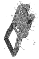
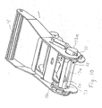
- Exemplary embodiments of the invention are now described with reference to the drawing, in which:
- Fig. 1
- shows a perspective view of a first embodiment of a strapping device according to the invention with the spindle in closed position;
- Fig. 2
- shows the same as
Fig. 1 in a side view; - Fig. 3
- shows the same as
Fig. 1 in a plan view from above; - Fig. 4
- shows a section on the line IV-IV in
Fig. 3 ; - Fig. 5
- shows a section on the line V-V in
Fig. 3 ; - Fig. 6
- shows the strapping device of
Fig. 1 in perspective view but with the spindle in open position; - Fig. 7
- shows the same as
Fig. 6 in a plan view from above; - Fig. 8
- shows the same as
Fig. 6 in a side view; - Fig. 9
- shows the same as
Fig. 6 in a view obliquely from above; - Fig. 10
- shows a perspective view of a second and preferred embodiment of a strapping device according to the invention with the spindle in closed position;
- Fig. 11
- shows the same as
Fig. 10 in a plan view from above; - Fig. 12
- shows a section on the line A-A in
Fig. 11 ; and - Figs. 13-16
- show details as sections B-B, C-C, D-D and E-E, respectively, of the embodiment in
Fig. 11 . - The strapping device according to the invention comprises several parts in common with prior art devices for tightening and securing straps or belts on loads to be transported or be held firm together or to a base.
- Both embodiments of the invention shown in the drawings include two mutually pivoting
frame parts number 3. Oneframe part 1 is provided with ahandle 4 for use in the tightening operation, and theother frame part 2 is provided with abolt 5 or rod member for securing the end of a not shown strap. - The
spindle 3 extends between and through opposing andparallel flanges frame parts spindle 3 when theparts ratchet wheels 9 which are fixed to thespindle 3 between theflanges parts pawls 10, 11 provided inrespective frame parts pawls 10, 11 can be released from engagement with theratchet wheels 9 by manually pulling thepawls 10, 11 back against the action of not shown springs. - A first and simple embodiment of the invention is shown in
Figs. 1-9 . - The new feature of the strapping device according to the invention is the special design of the
spindle 3. Thespindle 3 is adapted as a two-part member comprising abase member 12 and asmaller pivotable member 13. In the closed position, themembers slot 14 therebetween for receiving a not shown strap, seeFigs. 4 and 5 . The sectional view indicated by V-V onFig. 3 also defines a plane by which the angular position of the small pivotablemember 13 can be asserted. Thepivotable member 13 is provided as a round piece of rod which is bent at oneend 16 so as to provide a pivotable suspension of themember 13 when theend 16 is seated in a boring 17 in thebase member 12. Thepivotable member 13 is thereby able to pivot about anaxis 15, seeFig. 4 , theaxis 15 extending at right angles to thebase member 12. A stop in the form of a small projection or stoppin 18 is provided at the end of thebase member 12 opposite the end provided with the boring 17. In the open position of themember 13, it forms an angle with the plane mentioned above. - A second and preferred embodiment of the invention is shown in
Figs. 10 - 16 , where features in common with the first embodiment are denoted with the same reference numbers. - In the second embodiment of the strapping device of the invention, the
spindle 3 is also composed of two parts, abase member 12a and a slender pivotable member 13a. The main difference as compared with the first embodiment is that magnetic means are provided for keeping the pivotable member 13a in the closed position as described below, thus facilitating the operation. The magnetic means are here provided as a smallpermanent magnet 20 shaped as a disc which is embedded in a recess in the flat surface of thebase member 12a and secured by conventional means, e.g. by glue or press-fit, seeFig. 14 . Themagnet 20 is disposed close to thestop pin 18a so as to hold the free end of the pivotable member 13a close to or in contact with thestop pin 18a. - Other features of the second embodiment are the securing of the pivotable member 13a, the
stop pin 18a and thebase member 12a. These are all secured by spring-type tubular pins orcotter pins 21 lodged in bored holes in thebase member 12a, seeFigs. 10 ,13 and 16 . - The pivotable member 13a is provided with a
circumferential groove 22 at the part extending into thebase member 12a, and acotter pin 21 indicated onFig. 10 engages in a not shows way with thisgroove 22, retaining the member 13a in position while a the same time allowing the member 13a to pivot as described below. SeeFig. 15 . - The
pin 18a is provided with a through-going boring 23 in the part inserted in thebase member 12a, seeFig. 13 , thereby securing thepin 18a to thebase member 12a. - The
base member 12a is provided with through-goingcotter pins 21 in through-going holes at the ends that protrude laterally of the strapping device, se the detail inFig. 16 . - The strapping device according to the invention operates as follows.
- At first, the
small member 13 of the spindle is pivoted to the open position.Figs. 6 and7 shows themember 13 at an angle of about 60° from the closed position, but greater angles more than 90° are possible by the invention. Then the strap or belt, being the same as the one fitted on thebolt 5 or being a separate strap, is laid (not shown) in the free space over thebase member small member 13, 13a is then pivoted back to closed position shown onFigs. 1-5 and10 - 12 , abutting on thestop slot 14. Now theframe part 1 can be pivoted back and forth relative to thesecond frame part 2, thus providing a rotation in the direction indicated by arrow 19 onFig. 1 ; the pivoting action of the member 13a in the second embodiment is not shown but is completely analogous to that of the first embodiment of the strapping device. Thestop 18 will now retain the small pivotablemember 13, 13a in its closed position when the strap bears on themember 13, 13a due to the rotation of thespindle 3. Eventually, the strap is wound on thespindle 3 in the manner known from the prior art. - When the strap is to be released, the two
pawls 10, 11 are pulled back manually so as to make theratchet wheel 9 and thus thespindle 3 rotate in direction opposite the tightening direction 19. When the last winding is unrolled, the small pivotablemember 13, 13a will be carried and drawn by the strap from the closed position to the open position. The strap is thereby released and can be removed without any manipulation of themembers spindle 3. The invention thereby provides a more expedient and more time-saving operation than the hitherto known strapping devices. - Other embodiments of the invention are possible with the scope of the claims. The pivotable member of the spindle can have other shapes, e.g. rectangular in cross-section, and be composed of more than one part. The stop for limiting the pivoting of the pivotable member can be provided by other means, e.g. by a special configuration at the seating of the member. The magnetic means may be provided in other ways, e.g. by the stop pin itself being magnetic. Also the base member of the spindle can have other cross-sections than the partially circular shown in the drawings.
Claims (9)
- A load-strapping device including at least two frame parts (1,2) connected by a pivotable joint, where one frame part (2) is attached to a strap, where the joint between the pivotable parts (1,2) is provided with a spindle (3) extending between parallel flanges _ (7,8) of the frame parts (1,2) the pivotable joint between the pivotable parts (1,2) provided at opposite ends of the spindle with a pawl-and-ratchet mechanism (10,11) which provides one-way rotation of the spindle (3) when the pivotable basic parts (1,2) are pivoted repeatedly in opposing directions, the spindle (3) itself being a two-part design, where a first part (13) of the spindle (3) can be moved relatively to a second part (12) of the spindle in order to engage and/or release a strap between the parts (12,13) of the spindle (3), characterised in that the first part of the spindle (13) is suspended pivotably about a pivot axis (15) extending through one end of the spindle (3) and substantially at right angles to the spindle (3) so that the first part (13) can be pivoted between a closed position defined as substantially in parallel with the second part (12) of the spindle (3) and so that a plane containing the pivot axis (15) extends longitudinally through the first and second parts (13,12) of the spindle (3), and an open position defined as the first part (13) being pivoted so as to form an angle with the plane.
- Load-strapping device according to claim 1, wherein in the closed position, the first part (13) of the spindle (3) abuts with its distal end on a stop (18) provided in the device.
- Load-strapping device according to claim 2, wherein the distal end of the first part (13) of the spindle (3) is biased towards its closed position by magnetic means (20).
- Load-strapping device according to claim 3, wherein the magnetic means (20) for biasing the end of the spindle (3) towards its closed position comprises a permanent magnet embedded in the surface of the second part (12) of the spindle (3).
- Load-strapping device according to any preceding claim wherein the largest angle formed by first part (13) of the spindle (3) in the open position is at least 60°.
- Load-strapping device according to any of claim 2 - 5, wherein the first part (13) of the spindle (3) is made of a round rod with an angular bend at one end which extends into and is seated in the second part (12) of the spindle (3).
- Load-strapping device according to claim 6, wherein the first part (13) of the spindle (3) is secured by a spring-type pin or cotter pin (21) provided in a boring in the second part (13) of the spindle (3) and engaging a groove (22) in the end of the first part (13) of the spindle (3) seated in the second part (12) of the spindle (3).
- Load-strapping device according to claim 2, wherein the stop (18) is a cylindric pin seated in and extending above the surface the second part (13) of the spindle (3), and wherein the cylindric pin is secured by a spring-type pin or cotter pin (21) provided in a boring in the second part (12) of the spindle (3).
- Load-strapping device according to any preceding claim wherein the shape of the second part (12) of the spindle (3) is partially circular.
Applications Claiming Priority (2)
| Application Number | Priority Date | Filing Date | Title |
|---|---|---|---|
| DKBA201100056 | 2011-03-21 | ||
| PCT/DK2012/050083 WO2012126476A1 (en) | 2011-03-21 | 2012-03-20 | Load-strapping device |
Publications (2)
| Publication Number | Publication Date |
|---|---|
| EP2688767A1 EP2688767A1 (en) | 2014-01-29 |
| EP2688767B1 true EP2688767B1 (en) | 2015-02-18 |
Family
ID=46880093
Family Applications (1)
| Application Number | Title | Priority Date | Filing Date |
|---|---|---|---|
| EP12711749.7A Active EP2688767B1 (en) | 2011-03-21 | 2012-03-20 | Load-strapping device |
Country Status (10)
| Country | Link |
|---|---|
| US (1) | US9139124B2 (en) |
| EP (1) | EP2688767B1 (en) |
| CN (1) | CN203974660U (en) |
| AU (1) | AU2012231459B2 (en) |
| BR (1) | BR112013024259B1 (en) |
| CA (1) | CA2830867C (en) |
| DK (1) | DK2688767T3 (en) |
| ES (1) | ES2537176T3 (en) |
| RU (1) | RU2602907C2 (en) |
| WO (1) | WO2012126476A1 (en) |
Cited By (1)
| Publication number | Priority date | Publication date | Assignee | Title |
|---|---|---|---|---|
| RU183528U1 (en) * | 2017-12-01 | 2018-09-25 | Евгений Юрьевич Леоненко | Device for securing cargo |
Families Citing this family (12)
| Publication number | Priority date | Publication date | Assignee | Title |
|---|---|---|---|---|
| FI123234B (en) * | 2011-01-11 | 2012-12-31 | Topsun Logistics Control Co Ltd | Clamping device for load securing tape |
| GB201112792D0 (en) * | 2011-07-26 | 2011-09-07 | Smith Michael | A ratchet buckle use for the tightening of straps |
| US20150128388A1 (en) * | 2013-11-11 | 2015-05-14 | Cory Mastbeth | Binding apparatus, method and system |
| US10252661B2 (en) * | 2015-03-10 | 2019-04-09 | Ergolash Pat. Aps | Load-strapping device |
| USD826016S1 (en) * | 2016-05-02 | 2018-08-21 | Winston Products, Llc | Ratchet handle |
| GB2589923B (en) * | 2019-12-13 | 2021-12-08 | Three Smith Group Ltd | Strapping apparatus |
| USD1033204S1 (en) * | 2021-10-07 | 2024-07-02 | Winston Products Llc | Ratchet |
| USD1048863S1 (en) * | 2021-10-07 | 2024-10-29 | Winston Products Llc | Ratchet |
| USD1025753S1 (en) * | 2021-10-07 | 2024-05-07 | Winston Products, Llc | Ratchet |
| USD996954S1 (en) * | 2021-11-03 | 2023-08-29 | Transportation Ip Holdings, Llc | Tensioner |
| USD1106783S1 (en) * | 2023-11-17 | 2025-12-23 | Zhangjiagang City Xinhui Import and Export Trading Co., Ltd. | Ratchet tie down |
| USD1106782S1 (en) * | 2023-11-17 | 2025-12-23 | Zhangjiagang City Xinhui Import and Export Trading Co., Ltd. | Ratchet tie down |
Family Cites Families (15)
| Publication number | Priority date | Publication date | Assignee | Title |
|---|---|---|---|---|
| US2053976A (en) * | 1933-03-01 | 1936-09-08 | Columbus Mckinnon Chain Compan | Detent means for cable drums |
| SU1512834A1 (en) * | 1988-01-11 | 1989-10-07 | Могилевское Научно-Производственное Объединение По Разработке И Производству Прогрессивной Технологической Оснастки, Средств Механизации И Автоматизации | Arrangement for tensioning the stripping tape |
| SE503792C2 (en) * | 1995-03-22 | 1996-09-09 | Henry Norrby | Implements for applying traction in straps |
| US6648301B2 (en) * | 2002-02-07 | 2003-11-18 | I-Ming Lee | Structure manual tensioner |
| IL149079A0 (en) * | 2002-04-11 | 2002-11-10 | Mag Eh Ltd | A reeling device for a hoisting system |
| AU2005257681A1 (en) | 2004-06-25 | 2006-01-05 | Greyson Manufacturing Limited | A tensioning apparatus |
| US7350767B2 (en) * | 2005-03-03 | 2008-04-01 | Han-Ching Huang | Strapping apparatus |
| DE102005031735B3 (en) * | 2005-07-05 | 2007-05-10 | Spanset Inter Ag | Clamping ratchet for clamping and holding clamping devices |
| FI118371B (en) | 2006-04-04 | 2007-10-31 | Esa Takkinen | Load belt system drive |
| US7464915B2 (en) * | 2007-04-05 | 2008-12-16 | Kwang Wang Liu | Binding device |
| FR2915856B3 (en) | 2007-05-09 | 2009-04-24 | Wang Liu Kwang | FIXING DEVICE. |
| US7758023B2 (en) | 2007-07-11 | 2010-07-20 | Vincent Chang | Cargo bracing device |
| WO2009039372A2 (en) | 2007-09-19 | 2009-03-26 | Winston Breeden | Ratchet tie-down |
| US20100205790A1 (en) * | 2009-02-19 | 2010-08-19 | Weiguo Chen | Ratchet buckle with c-shape bar |
| CN102303713B (en) * | 2011-09-02 | 2013-09-25 | 浙江双友物流器械股份有限公司 | Quick tightener |
-
2012
- 2012-03-20 RU RU2013144661/11A patent/RU2602907C2/en active
- 2012-03-20 EP EP12711749.7A patent/EP2688767B1/en active Active
- 2012-03-20 AU AU2012231459A patent/AU2012231459B2/en not_active Ceased
- 2012-03-20 CA CA2830867A patent/CA2830867C/en active Active
- 2012-03-20 CN CN201290000532.XU patent/CN203974660U/en not_active Expired - Lifetime
- 2012-03-20 BR BR112013024259-0A patent/BR112013024259B1/en not_active IP Right Cessation
- 2012-03-20 US US14/006,666 patent/US9139124B2/en not_active Expired - Fee Related
- 2012-03-20 WO PCT/DK2012/050083 patent/WO2012126476A1/en not_active Ceased
- 2012-03-20 ES ES12711749.7T patent/ES2537176T3/en active Active
- 2012-03-20 DK DK12711749.7T patent/DK2688767T3/en active
Cited By (1)
| Publication number | Priority date | Publication date | Assignee | Title |
|---|---|---|---|---|
| RU183528U1 (en) * | 2017-12-01 | 2018-09-25 | Евгений Юрьевич Леоненко | Device for securing cargo |
Also Published As
| Publication number | Publication date |
|---|---|
| DK2688767T3 (en) | 2015-05-26 |
| EP2688767A1 (en) | 2014-01-29 |
| CA2830867A1 (en) | 2012-09-27 |
| ES2537176T3 (en) | 2015-06-03 |
| AU2012231459B2 (en) | 2016-06-30 |
| BR112013024259B1 (en) | 2021-01-19 |
| AU2012231459A1 (en) | 2013-10-10 |
| NZ616772A (en) | 2015-11-27 |
| BR112013024259A2 (en) | 2018-06-19 |
| US20140298629A1 (en) | 2014-10-09 |
| CA2830867C (en) | 2019-04-23 |
| CN203974660U (en) | 2014-12-03 |
| US9139124B2 (en) | 2015-09-22 |
| RU2013144661A (en) | 2015-04-27 |
| RU2602907C2 (en) | 2016-11-20 |
| WO2012126476A1 (en) | 2012-09-27 |
Similar Documents
| Publication | Publication Date | Title |
|---|---|---|
| US9139124B2 (en) | Load-strapping device | |
| US9469239B2 (en) | Side-loading ratchet device | |
| US7909306B2 (en) | Ratchet strapping device | |
| US8099836B2 (en) | Ratchet tie-down | |
| US20050278902A1 (en) | Strap-tensioning device with tension indicator | |
| US9010824B2 (en) | Cargo strap with handle | |
| US7377484B1 (en) | Multi-functional ratchet and associated method | |
| US7392973B1 (en) | Strap tensioner | |
| AU2016228500B2 (en) | Load-strapping device | |
| US10053022B2 (en) | Bicycle-carrying device for motor-vehicles | |
| US20100205790A1 (en) | Ratchet buckle with c-shape bar | |
| FR2550694A1 (en) | STRAP TENSIONER WITH LATCH | |
| EP2008867B1 (en) | Strap tensioner | |
| NZ616772B2 (en) | Load-strapping device | |
| HK1247165B (en) | Load-strapping device | |
| CA2626488A1 (en) | Apparatus for winding an elongate strap onto a winch |
Legal Events
| Date | Code | Title | Description |
|---|---|---|---|
| PUAI | Public reference made under article 153(3) epc to a published international application that has entered the european phase |
Free format text: ORIGINAL CODE: 0009012 |
|
| 17P | Request for examination filed |
Effective date: 20130924 |
|
| AK | Designated contracting states |
Kind code of ref document: A1 Designated state(s): AL AT BE BG CH CY CZ DE DK EE ES FI FR GB GR HR HU IE IS IT LI LT LU LV MC MK MT NL NO PL PT RO RS SE SI SK SM TR |
|
| AX | Request for extension of the european patent |
Extension state: BA |
|
| RAP1 | Party data changed (applicant data changed or rights of an application transferred) |
Owner name: QULATEC APS |
|
| 17Q | First examination report despatched |
Effective date: 20140409 |
|
| RAX | Requested extension states of the european patent have changed |
Extension state: BA Payment date: 20130924 |
|
| GRAP | Despatch of communication of intention to grant a patent |
Free format text: ORIGINAL CODE: EPIDOSNIGR1 |
|
| INTG | Intention to grant announced |
Effective date: 20140826 |
|
| GRAS | Grant fee paid |
Free format text: ORIGINAL CODE: EPIDOSNIGR3 |
|
| GRAA | (expected) grant |
Free format text: ORIGINAL CODE: 0009210 |
|
| AK | Designated contracting states |
Kind code of ref document: B1 Designated state(s): AL AT BE BG CH CY CZ DE DK EE ES FI FR GB GR HR HU IE IS IT LI LT LU LV MC MK MT NL NO PL PT RO RS SE SI SK SM TR |
|
| AX | Request for extension of the european patent |
Extension state: BA |
|
| RAP1 | Party data changed (applicant data changed or rights of an application transferred) |
Owner name: QULATEC APS |
|
| REG | Reference to a national code |
Ref country code: GB Ref legal event code: FG4D |
|
| REG | Reference to a national code |
Ref country code: CH Ref legal event code: EP |
|
| REG | Reference to a national code |
Ref country code: AT Ref legal event code: REF Ref document number: 710515 Country of ref document: AT Kind code of ref document: T Effective date: 20150315 |
|
| REG | Reference to a national code |
Ref country code: IE Ref legal event code: FG4D |
|
| REG | Reference to a national code |
Ref country code: DE Ref legal event code: R096 Ref document number: 602012005305 Country of ref document: DE Effective date: 20150402 |
|
| REG | Reference to a national code |
Ref country code: DK Ref legal event code: T3 Effective date: 20150521 |
|
| REG | Reference to a national code |
Ref country code: ES Ref legal event code: FG2A Ref document number: 2537176 Country of ref document: ES Kind code of ref document: T3 Effective date: 20150603 |
|
| REG | Reference to a national code |
Ref country code: SE Ref legal event code: TRGR |
|
| REG | Reference to a national code |
Ref country code: FR Ref legal event code: PLFP Year of fee payment: 4 |
|
| REG | Reference to a national code |
Ref country code: NL Ref legal event code: VDEP Effective date: 20150218 |
|
| REG | Reference to a national code |
Ref country code: NO Ref legal event code: T2 Effective date: 20150218 |
|
| REG | Reference to a national code |
Ref country code: AT Ref legal event code: MK05 Ref document number: 710515 Country of ref document: AT Kind code of ref document: T Effective date: 20150218 |
|
| REG | Reference to a national code |
Ref country code: LT Ref legal event code: MG4D |
|
| PG25 | Lapsed in a contracting state [announced via postgrant information from national office to epo] |
Ref country code: HR Free format text: LAPSE BECAUSE OF FAILURE TO SUBMIT A TRANSLATION OF THE DESCRIPTION OR TO PAY THE FEE WITHIN THE PRESCRIBED TIME-LIMIT Effective date: 20150218 Ref country code: FI Free format text: LAPSE BECAUSE OF FAILURE TO SUBMIT A TRANSLATION OF THE DESCRIPTION OR TO PAY THE FEE WITHIN THE PRESCRIBED TIME-LIMIT Effective date: 20150218 Ref country code: LT Free format text: LAPSE BECAUSE OF FAILURE TO SUBMIT A TRANSLATION OF THE DESCRIPTION OR TO PAY THE FEE WITHIN THE PRESCRIBED TIME-LIMIT Effective date: 20150218 |
|
| PG25 | Lapsed in a contracting state [announced via postgrant information from national office to epo] |
Ref country code: AT Free format text: LAPSE BECAUSE OF FAILURE TO SUBMIT A TRANSLATION OF THE DESCRIPTION OR TO PAY THE FEE WITHIN THE PRESCRIBED TIME-LIMIT Effective date: 20150218 Ref country code: RS Free format text: LAPSE BECAUSE OF FAILURE TO SUBMIT A TRANSLATION OF THE DESCRIPTION OR TO PAY THE FEE WITHIN THE PRESCRIBED TIME-LIMIT Effective date: 20150218 Ref country code: IS Free format text: LAPSE BECAUSE OF FAILURE TO SUBMIT A TRANSLATION OF THE DESCRIPTION OR TO PAY THE FEE WITHIN THE PRESCRIBED TIME-LIMIT Effective date: 20150618 Ref country code: NL Free format text: LAPSE BECAUSE OF FAILURE TO SUBMIT A TRANSLATION OF THE DESCRIPTION OR TO PAY THE FEE WITHIN THE PRESCRIBED TIME-LIMIT Effective date: 20150218 Ref country code: GR Free format text: LAPSE BECAUSE OF FAILURE TO SUBMIT A TRANSLATION OF THE DESCRIPTION OR TO PAY THE FEE WITHIN THE PRESCRIBED TIME-LIMIT Effective date: 20150519 Ref country code: LV Free format text: LAPSE BECAUSE OF FAILURE TO SUBMIT A TRANSLATION OF THE DESCRIPTION OR TO PAY THE FEE WITHIN THE PRESCRIBED TIME-LIMIT Effective date: 20150218 |
|
| PG25 | Lapsed in a contracting state [announced via postgrant information from national office to epo] |
Ref country code: SK Free format text: LAPSE BECAUSE OF FAILURE TO SUBMIT A TRANSLATION OF THE DESCRIPTION OR TO PAY THE FEE WITHIN THE PRESCRIBED TIME-LIMIT Effective date: 20150218 Ref country code: RO Free format text: LAPSE BECAUSE OF FAILURE TO SUBMIT A TRANSLATION OF THE DESCRIPTION OR TO PAY THE FEE WITHIN THE PRESCRIBED TIME-LIMIT Effective date: 20150218 Ref country code: EE Free format text: LAPSE BECAUSE OF FAILURE TO SUBMIT A TRANSLATION OF THE DESCRIPTION OR TO PAY THE FEE WITHIN THE PRESCRIBED TIME-LIMIT Effective date: 20150218 Ref country code: CZ Free format text: LAPSE BECAUSE OF FAILURE TO SUBMIT A TRANSLATION OF THE DESCRIPTION OR TO PAY THE FEE WITHIN THE PRESCRIBED TIME-LIMIT Effective date: 20150218 |
|
| REG | Reference to a national code |
Ref country code: CH Ref legal event code: PL |
|
| REG | Reference to a national code |
Ref country code: DE Ref legal event code: R097 Ref document number: 602012005305 Country of ref document: DE |
|
| PG25 | Lapsed in a contracting state [announced via postgrant information from national office to epo] |
Ref country code: MC Free format text: LAPSE BECAUSE OF FAILURE TO SUBMIT A TRANSLATION OF THE DESCRIPTION OR TO PAY THE FEE WITHIN THE PRESCRIBED TIME-LIMIT Effective date: 20150218 Ref country code: PL Free format text: LAPSE BECAUSE OF FAILURE TO SUBMIT A TRANSLATION OF THE DESCRIPTION OR TO PAY THE FEE WITHIN THE PRESCRIBED TIME-LIMIT Effective date: 20150218 |
|
| PLBE | No opposition filed within time limit |
Free format text: ORIGINAL CODE: 0009261 |
|
| STAA | Information on the status of an ep patent application or granted ep patent |
Free format text: STATUS: NO OPPOSITION FILED WITHIN TIME LIMIT |
|
| REG | Reference to a national code |
Ref country code: IE Ref legal event code: MM4A |
|
| 26N | No opposition filed |
Effective date: 20151119 |
|
| PG25 | Lapsed in a contracting state [announced via postgrant information from national office to epo] |
Ref country code: LI Free format text: LAPSE BECAUSE OF NON-PAYMENT OF DUE FEES Effective date: 20150331 Ref country code: IE Free format text: LAPSE BECAUSE OF NON-PAYMENT OF DUE FEES Effective date: 20150320 Ref country code: CH Free format text: LAPSE BECAUSE OF NON-PAYMENT OF DUE FEES Effective date: 20150331 |
|
| PG25 | Lapsed in a contracting state [announced via postgrant information from national office to epo] |
Ref country code: SI Free format text: LAPSE BECAUSE OF FAILURE TO SUBMIT A TRANSLATION OF THE DESCRIPTION OR TO PAY THE FEE WITHIN THE PRESCRIBED TIME-LIMIT Effective date: 20150218 |
|
| REG | Reference to a national code |
Ref country code: FR Ref legal event code: PLFP Year of fee payment: 5 |
|
| PG25 | Lapsed in a contracting state [announced via postgrant information from national office to epo] |
Ref country code: BE Free format text: LAPSE BECAUSE OF FAILURE TO SUBMIT A TRANSLATION OF THE DESCRIPTION OR TO PAY THE FEE WITHIN THE PRESCRIBED TIME-LIMIT Effective date: 20150218 |
|
| PG25 | Lapsed in a contracting state [announced via postgrant information from national office to epo] |
Ref country code: MT Free format text: LAPSE BECAUSE OF FAILURE TO SUBMIT A TRANSLATION OF THE DESCRIPTION OR TO PAY THE FEE WITHIN THE PRESCRIBED TIME-LIMIT Effective date: 20150218 |
|
| REG | Reference to a national code |
Ref country code: FR Ref legal event code: PLFP Year of fee payment: 6 |
|
| PG25 | Lapsed in a contracting state [announced via postgrant information from national office to epo] |
Ref country code: HU Free format text: LAPSE BECAUSE OF FAILURE TO SUBMIT A TRANSLATION OF THE DESCRIPTION OR TO PAY THE FEE WITHIN THE PRESCRIBED TIME-LIMIT; INVALID AB INITIO Effective date: 20120320 Ref country code: SM Free format text: LAPSE BECAUSE OF FAILURE TO SUBMIT A TRANSLATION OF THE DESCRIPTION OR TO PAY THE FEE WITHIN THE PRESCRIBED TIME-LIMIT Effective date: 20150218 Ref country code: BG Free format text: LAPSE BECAUSE OF FAILURE TO SUBMIT A TRANSLATION OF THE DESCRIPTION OR TO PAY THE FEE WITHIN THE PRESCRIBED TIME-LIMIT Effective date: 20150218 |
|
| PG25 | Lapsed in a contracting state [announced via postgrant information from national office to epo] |
Ref country code: CY Free format text: LAPSE BECAUSE OF FAILURE TO SUBMIT A TRANSLATION OF THE DESCRIPTION OR TO PAY THE FEE WITHIN THE PRESCRIBED TIME-LIMIT Effective date: 20150218 |
|
| PG25 | Lapsed in a contracting state [announced via postgrant information from national office to epo] |
Ref country code: PT Free format text: LAPSE BECAUSE OF FAILURE TO SUBMIT A TRANSLATION OF THE DESCRIPTION OR TO PAY THE FEE WITHIN THE PRESCRIBED TIME-LIMIT Effective date: 20150618 |
|
| PG25 | Lapsed in a contracting state [announced via postgrant information from national office to epo] |
Ref country code: TR Free format text: LAPSE BECAUSE OF FAILURE TO SUBMIT A TRANSLATION OF THE DESCRIPTION OR TO PAY THE FEE WITHIN THE PRESCRIBED TIME-LIMIT Effective date: 20150218 |
|
| PG25 | Lapsed in a contracting state [announced via postgrant information from national office to epo] |
Ref country code: LU Free format text: LAPSE BECAUSE OF NON-PAYMENT OF DUE FEES Effective date: 20150320 |
|
| REG | Reference to a national code |
Ref country code: FR Ref legal event code: PLFP Year of fee payment: 7 |
|
| PG25 | Lapsed in a contracting state [announced via postgrant information from national office to epo] |
Ref country code: MK Free format text: LAPSE BECAUSE OF FAILURE TO SUBMIT A TRANSLATION OF THE DESCRIPTION OR TO PAY THE FEE WITHIN THE PRESCRIBED TIME-LIMIT Effective date: 20150218 |
|
| PG25 | Lapsed in a contracting state [announced via postgrant information from national office to epo] |
Ref country code: AL Free format text: LAPSE BECAUSE OF FAILURE TO SUBMIT A TRANSLATION OF THE DESCRIPTION OR TO PAY THE FEE WITHIN THE PRESCRIBED TIME-LIMIT Effective date: 20150218 |
|
| PGFP | Annual fee paid to national office [announced via postgrant information from national office to epo] |
Ref country code: GB Payment date: 20220328 Year of fee payment: 11 Ref country code: DK Payment date: 20220329 Year of fee payment: 11 Ref country code: DE Payment date: 20220329 Year of fee payment: 11 |
|
| PGFP | Annual fee paid to national office [announced via postgrant information from national office to epo] |
Ref country code: SE Payment date: 20220327 Year of fee payment: 11 Ref country code: NO Payment date: 20220329 Year of fee payment: 11 Ref country code: IT Payment date: 20220322 Year of fee payment: 11 Ref country code: FR Payment date: 20220325 Year of fee payment: 11 |
|
| PGFP | Annual fee paid to national office [announced via postgrant information from national office to epo] |
Ref country code: ES Payment date: 20220401 Year of fee payment: 11 |
|
| REG | Reference to a national code |
Ref country code: DE Ref legal event code: R119 Ref document number: 602012005305 Country of ref document: DE |
|
| REG | Reference to a national code |
Ref country code: NO Ref legal event code: MMEP |
|
| REG | Reference to a national code |
Ref country code: SE Ref legal event code: EUG |
|
| REG | Reference to a national code |
Ref country code: DK Ref legal event code: EBP Effective date: 20230331 |
|
| GBPC | Gb: european patent ceased through non-payment of renewal fee |
Effective date: 20230320 |
|
| PG25 | Lapsed in a contracting state [announced via postgrant information from national office to epo] |
Ref country code: GB Free format text: LAPSE BECAUSE OF NON-PAYMENT OF DUE FEES Effective date: 20230320 |
|
| PG25 | Lapsed in a contracting state [announced via postgrant information from national office to epo] |
Ref country code: SE Free format text: LAPSE BECAUSE OF NON-PAYMENT OF DUE FEES Effective date: 20230321 Ref country code: NO Free format text: LAPSE BECAUSE OF NON-PAYMENT OF DUE FEES Effective date: 20230331 Ref country code: GB Free format text: LAPSE BECAUSE OF NON-PAYMENT OF DUE FEES Effective date: 20230320 Ref country code: FR Free format text: LAPSE BECAUSE OF NON-PAYMENT OF DUE FEES Effective date: 20230331 Ref country code: DE Free format text: LAPSE BECAUSE OF NON-PAYMENT OF DUE FEES Effective date: 20231003 |
|
| PG25 | Lapsed in a contracting state [announced via postgrant information from national office to epo] |
Ref country code: IT Free format text: LAPSE BECAUSE OF NON-PAYMENT OF DUE FEES Effective date: 20230320 Ref country code: DK Free format text: LAPSE BECAUSE OF NON-PAYMENT OF DUE FEES Effective date: 20230331 |
|
| REG | Reference to a national code |
Ref country code: ES Ref legal event code: FD2A Effective date: 20240507 |
|
| PG25 | Lapsed in a contracting state [announced via postgrant information from national office to epo] |
Ref country code: ES Free format text: LAPSE BECAUSE OF NON-PAYMENT OF DUE FEES Effective date: 20230321 |
|
| PG25 | Lapsed in a contracting state [announced via postgrant information from national office to epo] |
Ref country code: ES Free format text: LAPSE BECAUSE OF NON-PAYMENT OF DUE FEES Effective date: 20230321 |