EP2688466B1 - Détection de l'autonomie respiratoire - Google Patents
Détection de l'autonomie respiratoire Download PDFInfo
- Publication number
- EP2688466B1 EP2688466B1 EP12761355.2A EP12761355A EP2688466B1 EP 2688466 B1 EP2688466 B1 EP 2688466B1 EP 12761355 A EP12761355 A EP 12761355A EP 2688466 B1 EP2688466 B1 EP 2688466B1
- Authority
- EP
- European Patent Office
- Prior art keywords
- histogram
- ventilation
- controller
- hypoventilation
- peaks
- Prior art date
- Legal status (The legal status is an assumption and is not a legal conclusion. Google has not performed a legal analysis and makes no representation as to the accuracy of the status listed.)
- Active
Links
- 238000009423 ventilation Methods 0.000 title claims description 210
- 238000001514 detection method Methods 0.000 title description 21
- 206010021133 Hypoventilation Diseases 0.000 claims description 100
- 238000000034 method Methods 0.000 claims description 63
- 230000000241 respiratory effect Effects 0.000 claims description 40
- 230000029058 respiratory gaseous exchange Effects 0.000 claims description 22
- 208000000122 hyperventilation Diseases 0.000 claims description 21
- 230000000870 hyperventilation Effects 0.000 claims description 21
- 238000009826 distribution Methods 0.000 claims description 19
- 238000011156 evaluation Methods 0.000 claims description 19
- 230000008569 process Effects 0.000 claims description 10
- 208000008784 apnea Diseases 0.000 claims description 9
- 230000000737 periodic effect Effects 0.000 claims description 7
- 230000037007 arousal Effects 0.000 claims description 6
- 230000001131 transforming effect Effects 0.000 claims description 6
- 230000008859 change Effects 0.000 claims description 5
- 238000002560 therapeutic procedure Methods 0.000 claims description 4
- 230000000007 visual effect Effects 0.000 claims description 4
- 230000006870 function Effects 0.000 description 35
- 238000005516 engineering process Methods 0.000 description 29
- 239000007789 gas Substances 0.000 description 21
- 230000009466 transformation Effects 0.000 description 20
- 238000004458 analytical method Methods 0.000 description 14
- 238000012545 processing Methods 0.000 description 14
- 238000004364 calculation method Methods 0.000 description 8
- 230000003519 ventilatory effect Effects 0.000 description 8
- 238000013459 approach Methods 0.000 description 7
- QVGXLLKOCUKJST-UHFFFAOYSA-N atomic oxygen Chemical compound [O] QVGXLLKOCUKJST-UHFFFAOYSA-N 0.000 description 7
- 239000008280 blood Substances 0.000 description 7
- 210000004369 blood Anatomy 0.000 description 7
- 239000001301 oxygen Substances 0.000 description 7
- 229910052760 oxygen Inorganic materials 0.000 description 7
- 238000004422 calculation algorithm Methods 0.000 description 5
- 238000002496 oximetry Methods 0.000 description 5
- 238000012360 testing method Methods 0.000 description 5
- 238000013500 data storage Methods 0.000 description 4
- 239000012530 fluid Substances 0.000 description 4
- 208000001797 obstructive sleep apnea Diseases 0.000 description 4
- 206010021079 Hypopnoea Diseases 0.000 description 3
- 208000004166 Obesity Hypoventilation Syndrome Diseases 0.000 description 3
- 206010035004 Pickwickian syndrome Diseases 0.000 description 3
- 230000002902 bimodal effect Effects 0.000 description 3
- 238000010586 diagram Methods 0.000 description 3
- 238000012544 monitoring process Methods 0.000 description 3
- 238000000638 solvent extraction Methods 0.000 description 3
- 206010021143 Hypoxia Diseases 0.000 description 2
- 230000008901 benefit Effects 0.000 description 2
- 238000011513 continuous positive airway pressure therapy Methods 0.000 description 2
- 238000000537 electroencephalography Methods 0.000 description 2
- 230000036044 hypoxaemia Effects 0.000 description 2
- 230000003434 inspiratory effect Effects 0.000 description 2
- 238000005259 measurement Methods 0.000 description 2
- 239000012528 membrane Substances 0.000 description 2
- 238000005192 partition Methods 0.000 description 2
- 238000002106 pulse oximetry Methods 0.000 description 2
- 230000004044 response Effects 0.000 description 2
- 238000005096 rolling process Methods 0.000 description 2
- 238000003860 storage Methods 0.000 description 2
- 238000012546 transfer Methods 0.000 description 2
- 208000006545 Chronic Obstructive Pulmonary Disease Diseases 0.000 description 1
- 230000002547 anomalous effect Effects 0.000 description 1
- 230000015572 biosynthetic process Effects 0.000 description 1
- 238000012512 characterization method Methods 0.000 description 1
- 238000007635 classification algorithm Methods 0.000 description 1
- 238000004891 communication Methods 0.000 description 1
- 238000012790 confirmation Methods 0.000 description 1
- 230000001351 cycling effect Effects 0.000 description 1
- 238000013481 data capture Methods 0.000 description 1
- 238000011157 data evaluation Methods 0.000 description 1
- 238000003745 diagnosis Methods 0.000 description 1
- 238000002405 diagnostic procedure Methods 0.000 description 1
- 238000007599 discharging Methods 0.000 description 1
- 201000010099 disease Diseases 0.000 description 1
- 208000037265 diseases, disorders, signs and symptoms Diseases 0.000 description 1
- 238000001914 filtration Methods 0.000 description 1
- 238000009499 grossing Methods 0.000 description 1
- 230000000977 initiatory effect Effects 0.000 description 1
- 230000010354 integration Effects 0.000 description 1
- 230000007774 longterm Effects 0.000 description 1
- 238000005457 optimization Methods 0.000 description 1
- 238000001441 oximetry spectrum Methods 0.000 description 1
- 238000007781 pre-processing Methods 0.000 description 1
- 230000002035 prolonged effect Effects 0.000 description 1
- 230000000306 recurrent effect Effects 0.000 description 1
- 238000012552 review Methods 0.000 description 1
- 238000005070 sampling Methods 0.000 description 1
- 238000012216 screening Methods 0.000 description 1
- 230000000153 supplemental effect Effects 0.000 description 1
- 230000001225 therapeutic effect Effects 0.000 description 1
Images


Classifications
-
- A—HUMAN NECESSITIES
- A61—MEDICAL OR VETERINARY SCIENCE; HYGIENE
- A61M—DEVICES FOR INTRODUCING MEDIA INTO, OR ONTO, THE BODY; DEVICES FOR TRANSDUCING BODY MEDIA OR FOR TAKING MEDIA FROM THE BODY; DEVICES FOR PRODUCING OR ENDING SLEEP OR STUPOR
- A61M16/00—Devices for influencing the respiratory system of patients by gas treatment, e.g. mouth-to-mouth respiration; Tracheal tubes
- A61M16/0051—Devices for influencing the respiratory system of patients by gas treatment, e.g. mouth-to-mouth respiration; Tracheal tubes with alarm devices
-
- A—HUMAN NECESSITIES
- A61—MEDICAL OR VETERINARY SCIENCE; HYGIENE
- A61B—DIAGNOSIS; SURGERY; IDENTIFICATION
- A61B5/00—Measuring for diagnostic purposes; Identification of persons
- A61B5/08—Detecting, measuring or recording devices for evaluating the respiratory organs
- A61B5/083—Measuring rate of metabolism by using breath test, e.g. measuring rate of oxygen consumption
-
- A—HUMAN NECESSITIES
- A61—MEDICAL OR VETERINARY SCIENCE; HYGIENE
- A61B—DIAGNOSIS; SURGERY; IDENTIFICATION
- A61B5/00—Measuring for diagnostic purposes; Identification of persons
- A61B5/08—Detecting, measuring or recording devices for evaluating the respiratory organs
- A61B5/087—Measuring breath flow
-
- A—HUMAN NECESSITIES
- A61—MEDICAL OR VETERINARY SCIENCE; HYGIENE
- A61M—DEVICES FOR INTRODUCING MEDIA INTO, OR ONTO, THE BODY; DEVICES FOR TRANSDUCING BODY MEDIA OR FOR TAKING MEDIA FROM THE BODY; DEVICES FOR PRODUCING OR ENDING SLEEP OR STUPOR
- A61M16/00—Devices for influencing the respiratory system of patients by gas treatment, e.g. mouth-to-mouth respiration; Tracheal tubes
- A61M16/0057—Pumps therefor
- A61M16/0066—Blowers or centrifugal pumps
- A61M16/0069—Blowers or centrifugal pumps the speed thereof being controlled by respiratory parameters, e.g. by inhalation
-
- A—HUMAN NECESSITIES
- A61—MEDICAL OR VETERINARY SCIENCE; HYGIENE
- A61M—DEVICES FOR INTRODUCING MEDIA INTO, OR ONTO, THE BODY; DEVICES FOR TRANSDUCING BODY MEDIA OR FOR TAKING MEDIA FROM THE BODY; DEVICES FOR PRODUCING OR ENDING SLEEP OR STUPOR
- A61M16/00—Devices for influencing the respiratory system of patients by gas treatment, e.g. mouth-to-mouth respiration; Tracheal tubes
- A61M16/021—Devices for influencing the respiratory system of patients by gas treatment, e.g. mouth-to-mouth respiration; Tracheal tubes operated by electrical means
- A61M16/022—Control means therefor
- A61M16/024—Control means therefor including calculation means, e.g. using a processor
-
- A—HUMAN NECESSITIES
- A61—MEDICAL OR VETERINARY SCIENCE; HYGIENE
- A61B—DIAGNOSIS; SURGERY; IDENTIFICATION
- A61B5/00—Measuring for diagnostic purposes; Identification of persons
- A61B5/72—Signal processing specially adapted for physiological signals or for diagnostic purposes
- A61B5/7235—Details of waveform analysis
- A61B5/7264—Classification of physiological signals or data, e.g. using neural networks, statistical classifiers, expert systems or fuzzy systems
-
- A—HUMAN NECESSITIES
- A61—MEDICAL OR VETERINARY SCIENCE; HYGIENE
- A61M—DEVICES FOR INTRODUCING MEDIA INTO, OR ONTO, THE BODY; DEVICES FOR TRANSDUCING BODY MEDIA OR FOR TAKING MEDIA FROM THE BODY; DEVICES FOR PRODUCING OR ENDING SLEEP OR STUPOR
- A61M16/00—Devices for influencing the respiratory system of patients by gas treatment, e.g. mouth-to-mouth respiration; Tracheal tubes
- A61M16/0003—Accessories therefor, e.g. sensors, vibrators, negative pressure
- A61M2016/0027—Accessories therefor, e.g. sensors, vibrators, negative pressure pressure meter
-
- A—HUMAN NECESSITIES
- A61—MEDICAL OR VETERINARY SCIENCE; HYGIENE
- A61M—DEVICES FOR INTRODUCING MEDIA INTO, OR ONTO, THE BODY; DEVICES FOR TRANSDUCING BODY MEDIA OR FOR TAKING MEDIA FROM THE BODY; DEVICES FOR PRODUCING OR ENDING SLEEP OR STUPOR
- A61M16/00—Devices for influencing the respiratory system of patients by gas treatment, e.g. mouth-to-mouth respiration; Tracheal tubes
- A61M16/0003—Accessories therefor, e.g. sensors, vibrators, negative pressure
- A61M2016/003—Accessories therefor, e.g. sensors, vibrators, negative pressure with a flowmeter
- A61M2016/0033—Accessories therefor, e.g. sensors, vibrators, negative pressure with a flowmeter electrical
- A61M2016/0039—Accessories therefor, e.g. sensors, vibrators, negative pressure with a flowmeter electrical in the inspiratory circuit
-
- A—HUMAN NECESSITIES
- A61—MEDICAL OR VETERINARY SCIENCE; HYGIENE
- A61M—DEVICES FOR INTRODUCING MEDIA INTO, OR ONTO, THE BODY; DEVICES FOR TRANSDUCING BODY MEDIA OR FOR TAKING MEDIA FROM THE BODY; DEVICES FOR PRODUCING OR ENDING SLEEP OR STUPOR
- A61M2205/00—General characteristics of the apparatus
- A61M2205/15—Detection of leaks
-
- A—HUMAN NECESSITIES
- A61—MEDICAL OR VETERINARY SCIENCE; HYGIENE
- A61M—DEVICES FOR INTRODUCING MEDIA INTO, OR ONTO, THE BODY; DEVICES FOR TRANSDUCING BODY MEDIA OR FOR TAKING MEDIA FROM THE BODY; DEVICES FOR PRODUCING OR ENDING SLEEP OR STUPOR
- A61M2205/00—General characteristics of the apparatus
- A61M2205/18—General characteristics of the apparatus with alarm
-
- A—HUMAN NECESSITIES
- A61—MEDICAL OR VETERINARY SCIENCE; HYGIENE
- A61M—DEVICES FOR INTRODUCING MEDIA INTO, OR ONTO, THE BODY; DEVICES FOR TRANSDUCING BODY MEDIA OR FOR TAKING MEDIA FROM THE BODY; DEVICES FOR PRODUCING OR ENDING SLEEP OR STUPOR
- A61M2205/00—General characteristics of the apparatus
- A61M2205/35—Communication
- A61M2205/3546—Range
- A61M2205/3553—Range remote, e.g. between patient's home and doctor's office
-
- A—HUMAN NECESSITIES
- A61—MEDICAL OR VETERINARY SCIENCE; HYGIENE
- A61M—DEVICES FOR INTRODUCING MEDIA INTO, OR ONTO, THE BODY; DEVICES FOR TRANSDUCING BODY MEDIA OR FOR TAKING MEDIA FROM THE BODY; DEVICES FOR PRODUCING OR ENDING SLEEP OR STUPOR
- A61M2205/00—General characteristics of the apparatus
- A61M2205/50—General characteristics of the apparatus with microprocessors or computers
- A61M2205/502—User interfaces, e.g. screens or keyboards
-
- A—HUMAN NECESSITIES
- A61—MEDICAL OR VETERINARY SCIENCE; HYGIENE
- A61M—DEVICES FOR INTRODUCING MEDIA INTO, OR ONTO, THE BODY; DEVICES FOR TRANSDUCING BODY MEDIA OR FOR TAKING MEDIA FROM THE BODY; DEVICES FOR PRODUCING OR ENDING SLEEP OR STUPOR
- A61M2230/00—Measuring parameters of the user
- A61M2230/40—Respiratory characteristics
- A61M2230/43—Composition of exhalation
- A61M2230/435—Composition of exhalation partial O2 pressure (P-O2)
Definitions
- the present technology relates to methods and apparatus for detection of respiratory ventilation sufficiency or insufficiency, such as normal patient ventilation, hyperventilation or hypoventilation.
- a form of pressure treatment typically for patients with obstructive sleep apnea (OSA) is continuous positive airway pressure (CPAP) applied by a blower (compressor) via a connecting hose and mask.
- CPAP continuous positive airway pressure
- the positive pressure may be used to prevent collapse of the patient's airway during inspiration, thus preventing recurrent apnoeas or hypopnoeas and their sequelae.
- Such a respiratory treatment apparatus can function to generate a supply of clean breathable gas (usually air, with or without supplemental oxygen) at the therapeutic pressure or pressures that may change to treat different events but may remain approximately constant across a given cycle of the patient respiration cycle (i.e., inspiration and expiration) or may be reduced for comfort during each expiration (e.g., bi-level CPAP).
- a supply of clean breathable gas usually air, with or without supplemental oxygen
- Respiratory treatment apparatus can typically include a flow generator, an air filter, a mask or cannula, an air delivery conduit connecting the flow generator to the mask, various sensors and a microprocessor-based controller.
- the flow generator may include a servo-controlled motor and an impeller.
- the flow generator may also include a valve capable of discharging air to atmosphere as a means for altering the pressure delivered to the patient as an alternative to motor speed control.
- the sensors measure, amongst other things, motor speed, gas volumetric flow rate and outlet pressure, such as with a pressure transducer, flow sensor or the like.
- the apparatus may optionally include a humidifier and/or heater elements in the path of the air delivery circuit.
- the controller may include data storage capacity with or without integrated data retrieval/transfer and display functions.
- US 2007/073181 discloses systems and methods said to provide for detecting respiration disturbances and changes in respiration disturbances, preferably by detecting variability in one or more respiration parameters.
- a footprint such as a two- or three-dimensional histogram, is generated that is representative of a patient's respiration parameter variability, and one or more indices representative of quantitative measurements of the footprint are generated.
- WO 03/030804 discloses a pressure support system and method of treating disordered breathing that is said to optimize the pressure delivered to the patient to treat the disordered breathing while minimizing the delivered pressure for patient comfort.
- the pressure support system also controls the pressure provided to the patient based on the variability of the monitored data and a trend analysis of this data, including an indication of the skewness of the patient's inspiratory waveform.
- US 2006/282002 discloses a respiratory testing system having a fluid chamber enclosing a fluid medium and having a flexible membrane deflectable by the application of a respiratory gas flow, a pressure sensor configured to sense a pressure variation of the fluid medium in response to a deflection of the flexible membrane, and a processing circuit configured to compute a respiratory flow data from a pressure variation of the fluid medium.
- hypoventilation may be considered an occurrence of a persistently low ventilation as opposed to a periodic pause or apnoea. Such incidents of hypoventilation may not be recorded or recognized by the patient or by a clinician or physician managing the patient.
- hypoventilation may present for a number of reasons:
- the patient may have a primary diagnosis of obesity hypoventilation syndrome (OHS) and CPAP is being trialed as a therapy. Many patients recover over months with such treatment. Although overnight oxygen blood saturation (SpO 2 ) recording is the standard way of identifying efficacy, this is potentially costly and cumbersome.
- OOS obesity hypoventilation syndrome
- SpO 2 overnight oxygen blood saturation
- the patient may develop hypoventilation over time due to an underlying disease process (e.g., chronic obstructive pulmonary disease (COPD) progression or OHS progression from obstructive sleep apnea (OSA)).
- COPD chronic obstructive pulmonary disease
- OSA obstructive sleep apnea
- the patient may have had a limited diagnostic test where the hypoventilation was missed or, for example, they did not enter the sleep state where hypoventilation presents (e.g., supine sleep).
- a first aspect of some embodiments of the present technology is to provide methods and devices for assessing ventilation.
- Another aspect of some embodiments of the technology is to determine a ventilation histogram in an apparatus based on a measure of respiratory flow from a flow sensor.
- a still further aspect of the technology is to implement the detection of ventilation sufficiency in a respiratory treatment apparatus, such as a continuous positive airway pressure device, based on or as a function of a ventilation histogram.
- Another aspect of the present technology is a method for detecting hypoventilation comprising the steps of: (i) determining a measure of flow; (ii) calculating a measure of ventilation from said measure of flow; (iii) determining a probability distribution of said measure of ventilation; and (iv) analyzing the probability distribution to detect hypoventilation.
- Some embodiments of the technology involve a method for controlling a processor to assess sufficiency of ventilation from a measured flow of breathable gas.
- Such a method of the processor may include accessing a measure of a flow of breathable gas representative of patient respiration, deriving measures of ventilation from the measure of flow, and determining, with a processor, a histogram based on the measures of ventilation.
- Such a method may also involve displaying a - graph of the histogram on a visual display device.
- the histogram may represent a frequency distribution of ventilation values taken over the course of a treatment session where each ventilation value is a measure of volume over a time interval.
- the time interval may be shorter than the time of the treatment session.
- the time interval may be on an order of a minute and the time of the treatment session may be on an order of hours.
- the method may further involve processing, in the processor, data associated with the histogram to calculate a skewness index, comparing the skewness index to a threshold, and indicating hypoventilation or hyperventilation based on the comparison.
- the method may also include processing, in the processor, data associated with the histogram to detect a number of peaks of the histogram, and indicating a presence or absence of hypoventilation based on the number of detected peaks.
- method may also include processing, in the processor, data associated with the histogram to determine a kurtosis index, comparing the kurtosis index to a threshold, and indicating a presence or absence of hypoventilation based on the comparison.
- such a method may further include controlling, with the processor, measuring of the flow of breathable gas with a flow sensor.
- the method may include processing data representing the histogram to generate a hypoventilation indicator where the indicator represents an occurrence of an event of hypoventilation.
- the hypoventilation indicator may include a probability value.
- the processing may include a detection of peaks of the histogram.
- the processing may also include calculating a distance between peaks of the histogram and transforming the distance into a probability space.
- the processing may also include calculating a gradient between peaks of the histogram.
- the processing may also include calculating an area with respect to the gradient and transforming the area into a probability space.
- the processing may also include calculating a set of features of the histogram and generating the indicator based on an evaluation of the set of features.
- the set of features may include one or more of the following features: a gradient between two largest peaks, a gradient between a largest peak and a center point, a gradient between a second largest peak and a center point, an area between two largest peaks, an area between a largest peak and a center point, an area between a second largest peak and a center point, a shape feature, kurtosis value and skewness value.
- the method may further involve determining a measure of leak and distinguishing measures of ventilation for the histogram based on the measure of leak, such as by partitioning a histogram for display accordingly and/or by disregarding ventilation measures corresponding to periods of leak.
- the method may involve determining a measure of ventilation stability and distinguishing measures of ventilation for the histogram based on the measure of stability, such as by partitioning a histogram for display accordingly and/or by disregarding ventilation measures corresponding to periods of instability.
- the determining of the measure of ventilation stability may involve any of one or more of a detection of an awake period, an apnea event, a periodic breathing event and an arousal event.
- Some embodiments of the present technology may include a ventilation assessment apparatus.
- the apparatus may typically include a controller having at least one processor to access data representing a measured flow of breathable gas attributable to patient respiration, the controller being further configured to (a) derive measures of ventilation from the measure of flow, and (b) determine a histogram based on the measures of ventilation.
- the controller may be further configured to display a graph of the histogram on a visual display device.
- the histogram may represent a frequency distribution of ventilation values taken over the course of a treatment session where each ventilation value may be a measure of volume over a time interval.
- the time interval may be shorter than the time of the treatment session.
- the time interval may be on an order of a minute and the time of the treatment session is on an order of hours.
- the controller may also be configured to process data associated with the histogram to calculate a skewness index, to compare the skewness index to a threshold, and to indicate an occurrence of hypoventilation or hyperventilation based on the comparison.
- the controller may also be configured to process data associated with the histogram to detect a number of peaks of the histogram, and to indicate a presence or absence of hypoventilation based on the number of detected peaks.
- the controller may also be configured to process data associated with the histogram to determine a kurtosis index, to compare the kurtosis index to a threshold, and to indicate a presence or absence of hypoventilation based on the comparison.
- the apparatus may also include a flow sensor, and the controller may also be configured to control measuring of the flow of breathable gas with the flow sensor.
- the apparatus may also include a flow generator configured to produce a breathable gas for a patient at a pressure above atmospheric pressure.
- the controller may also be configured to control the flow generator to produce the breathable gas according to a pressure therapy regime based on an assessment of any one or more of (a) the histogram, (b) a number of peaks of the histogram, (c) a kurtosis index determined from data associated with the histogram and (d) a skewness index determined from data associated with the histogram.
- the controller may be configured to process data representing the histogram to generate a hypoventilation indicator where the indicator represents an occurrence of an event of hypoventilation.
- the hypoventilation indicator may include a probability value.
- the controller may also be configured to detect peaks of the histogram.
- the controller may also be configured to calculate a distance between peaks of the histogram and transforming the distance into a probability space.
- the controller may be configured to calculate a gradient between peaks of the histogram.
- the controller may also be configured to calculate an area with respect to the gradient and transform the area into a probability space.
- the controller may also be configured to calculate a set of features of the histogram and to generate the indicator based on an evaluation of the set of features.
- the set of features may include one or more of the following features: a gradient between two largest peaks, a gradient between a largest peak and a center point, a gradient between a second largest peak and a center point, an area between two largest peaks, an area between a largest peak and a center point, an area between a second largest peak and a center point, a shape feature, kurtosis value and skewness value.
- the controller may be configured to determine a measure of leak and to distinguish the measures of ventilation for the histogram based on the measure of leak. Still further, the controller may be configured to determine a measure of ventilation stability and to distinguish the measures of ventilation for the histogram based on the measure of stability. The controller may determine the measure of ventilation stability by detecting any of one or more of an awake period, an apnea event, a periodic breathing event and an arousal event.
- the system may include means for measuring a flow of breathable gas attributable to patient respiration during a treatment session, means for deriving measures of ventilation from the measure of flow, and means for determining a histogram based on the measures of ventilation.
- Such a system may also include means for displaying a visual graph of the histogram. It may also include means for evaluating a skewness index based on data associated with the histogram to detect an occurrence of hypoventilation or hyperventilation. The system may also include means for evaluating a number of histogram peaks from data associated with the histogram to detect an occurrence of hypoventilation. It may also include means for evaluating a kurtosis index based on data associated with the histogram to detect a presence or absence of hypoventilation.
- the system may also include means for generating a breathable gas for a patient at a pressure above atmospheric pressure based on an assessment of any one or more of (a) the histogram, (b) a number of peaks of the histogram, (c) a kurtosis index determined from data associated with the histogram and (d) a skewness index determined from data associated with the histogram.
- the system may also include means for processing data representing the histogram to generate a hypoventilation indicator where the indicator represents an occurrence of an event of hypoventilation.
- the hypoventilation indicator may include a probability value.
- the system may also include means for detecting peaks of the histogram.
- the system may also include means for calculating a distance between peaks of the histogram and transforming the distance into a probability space.
- the system may also include means for calculating a gradient between peaks of the histogram.
- the system may also include means for calculating an area with respect to the gradient and transforming the area into a probability space.
- the system may also include means for calculating a set of features of the histogram and generating the indicator based on an evaluation of the set of features.
- the set of features may include one or more of the following features: a gradient between two largest peaks, a gradient between a largest peak and a center point, a gradient between a second largest peak and a center point, an area between two largest peaks, an area between a largest peak and a center point, an area between a. second largest peak and a center point, a shape feature, kurtosis value and skewness value.
- the system may include a leak detector to determine a measure of leak.
- the system may be configured to distinguish the measures of ventilation for the histogram based on the measure of leak.
- the system may include a ventilation stability detector.
- the system may be configured to distinguish the measures of ventilation for the histogram based on the measure of stability.
- the ventilation stability detector may include means for detecting any one or more of an awake period, an apnea event, a periodic breathing event and an arousal event.
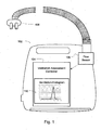
- embodiments of the present technology may include a ventilation assessment device 102 or apparatus having a controller 104 that may have one or more processors to implement particular ventilation assessment methodologies such as the algorithms described in more detail herein.
- the ventilation assessment may provide a determination of ventilation adequacy such as by determining an incident of hyperventilation or hypoventilation.
- the ventilation assessment may also optionally provide information for making such a determination such as by generating or analyzing a ventilation histogram.
- An example of a plotted ventilation histogram 110 is shown in FIG. 1 .
- the device or apparatus may include integrated chips, a memory and/or other control .instruction, data or information storage medium.
- programmed instructions encompassing the assessment methodologies may be coded on integrated chips in the memory of the device or apparatus to form an application specific integrated chip (ASIC).
- ASIC application specific integrated chip
- Such instructions may also or alternatively be loaded as software or firmware using an appropriate data storage medium.
- the device can be used for processing data from a flow signal.
- the processor may control the assessment of patient ventilation as described in the embodiments discussed in more detail herein based on accessing measured and recorded respiratory flow data from a prior sleep session.
- the ventilation assessment may be performed during a sleep session contemporaneously with the measuring of a respiratory flow signal.
- the device or apparatus itself may optionally be implemented with a flow sensor 106 for measuring a flow signal for use with the implemented methodologies. For example, flow to or through a nasal cannula 108 or mask may be measured using a pneumotachograph and differential pressure transducer or similar device such as one employing a bundle of tubes or ducts to derive a flow signal.
- a patient respiratory flow signal may be determined by subtracting estimated measures of vent flow and leak flow from the measure of total flow produced by a flow sensor such as in the case that that flow sensor measures a flow of gas in addition to patient respiratory flow.
- a flow signal may be inferred from other sensors, such as, a motor current sensor as ' described in PCT/AU2005/001688 filed on Nov. 2, 2005 , and U.S. Patent Application No. 12/294,957 , the National Stage thereof.
- a flow signal may be generated by a non-contact sensor such as by a pulse radio frequency transceiver and signal processing of reflected pulse radio frequency signals or by an ultrasonic screening sensor.
- the sensor may monitor sound such as by the use of ultrasonic sensors to detect respiratory parameters such as a respiratory flow signal from the signals measured by the sensors.
- an automated assessment of ventilation by an assessment device may involve a determination or calculation of a ventilation histogram, which may be based on data representing a measure of a flow of breathable gas or a respiratory flow signal.
- a controller or processor may access a measure of a flow of breathable gas representative of patient respiration that may be taken during the course of a treatment session, such as a night sleep or several hours of treatment.
- the controller or processor may then derive a measure of patient ventilation or measures of ventilation from the measure of flow.
- the measure of ventilation may typically be a signal representing a volume of air inspired or expired over a period of time.
- such a measure may be determined as a low pass filtered absolute value of the respiratory flow.
- a low pass filter may be implemented with a time constant on the order of minutes. For example, it may be in the range of 60 to 200 seconds but preferably about 180 seconds.
- the measure may be partitioned or sampled to determine discrete measures from the ventilation signal.
- each value of these measures of ventilation may be represented as a number of liters inspired or expired per minute (e.g., measures of minute ventilation).
- the measures of ventilation may be the measured tidal volume for each respiratory cycle during a treatment session, such as the liters per cycle.
- a ventilation histogram may be determined based on the measures of ventilation by a processor. For example, a frequency distribution of the measures of ventilation taken over the course of a treatment session may be computed. For example, the determined ventilation values may be compared to discrete intervals (e.g., at or about a liter per minute) to determine how frequent all of the measured ventilation values are in the different intervals.
- the ventilation histogram may be plotted such that the interval or intervals with a high frequency or greatest frequency (e.g., one or more peaks) may be observed.
- the data associated therewith may be evaluated by a processor such that the interval or intervals with a high frequency or greatest frequency (e.g., one or more peaks) may be detected.
- the data may also be evaluated to determine skewness and/or peakedness (e.g., kurtosis).
- the data associated with the ventilation histogram may also be evaluated to determine one or more of the following features: a shape feature of the ventilation histogram; the gradient of the line connecting the two largest peaks in the ventilation histogram; the gradient of the line connecting the highest peak and the center point of the ventilation histogram; the gradient of the line connecting the 2 nd highest peak and the center point of the ventilation histogram; the area below the center point and the highest peak of the ventilation histogram; the area below the center point and 2 nd highest peak of a ventilation histogram; the distance between the two highest peaks.
- the ventilation assessment device in addition to determining a ventilation histogram, may also score or record incidents of hypoventilation or hyperventilation.
- the scoring of such incidents may optionally include an identification of the derived ventilation values that are indicative of the hyperventilation or hypoventilation incident.
- the scoring may also include an identification of a time or of one or more time periods during a treatment session when the incident occurred and/or the duration of the incident.
- FIG. 3 is a plot of respiratory data from a well-treated patient on CPAP during the course of a single night's treatment session.
- the included traces are (top-to-bottom), respiratory flow 330F, ventilation 330V, oxygen blood saturation (SpO 2 ) 330S and leak 330L.
- the ventilation signal which is a low pass filtered absolute value of the respiratory flow signal with a time constant of 180 seconds, is stable over the whole night.
- the SpO 2 signal 330S is flat, not falling below about 94% at any time during the night.
- the leak signal 330L is also well controlled in that there are no substantial incidents of leak.
- Fig. 4 shows a plotted ventilation histogram 110-N determined from the data of the ventilation signal 330V for the night.
- the ventilation values were assessed in bins or intervals of about 0.5 liters per minute.
- the frequency associated with each bin or interval may be determined as a percentage of the total treatment session (e.g., by the number of observed or sampled ventilation values in each interval divided by the total number of observed or sampled ventilation values during one treatment session).
- a determination that a single peak exists in the histogram and that the single peak is associated with an adequate ventilation value may be taken as an indicator of normal patient ventilation for the session.
- Ventilation histograms may be utilized for the ventilation histograms.
- the above ventilation histogram is illustrated showing a frequency distribution of minute ventilation values over the course of a single treatment session, some embodiments may also optionally permit generation of ventilation histograms using ventilation values from multiple treatment sessions (e.g., one week or one month of treatment sessions etc.).
- bin width 0.5 liters/minute was chosen.
- bins can be set up in any way possible. There may be some standard strategies for histogram determination and bin selection that may be useful.
- Such a histogram may be calculated by:
- the bin width and origin point may have an important role in effectively characterizing the distribution of data.
- Another way to view the bin width parameter is to look at it as a smoothing parameter. If the bin width is too large, then the histogram will look flat, while if the bin width is too small, it will simply replicate the data. Thus, it can be important to choose an appropriate bin width.
- bin width There are a number of possible methods of choosing bin width:
- the histogram algorithm may include a method for dynamically determining bin width such that the bin width may be variable.
- variable bin width may be useful in characterizing sparsely distributed, datasets. For example, if a patient has only limited time period where a hypoventilation episode was experienced, using a constant bin width may not present or detect this clearly. In such situations the use of a variable bin width can become very useful.
- Another implementation of the ventilation assessment methodology could be based on use of a kernel density estimator to capture the distribution of the ventilation signal.
- An advantage of this approach may be that it can effectively capture sharp features in the distribution, which in the case of characterizing the ventilation signal may become very useful. Furthermore, the selection of the origin point will not affect the characterization of the distribution.
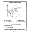
- FIG. 5 is a plot of respiratory data from a patient on CPAP experiencing hypoventilation during the course of a single night's treatment session.
- the included traces are (top-to-bottom), electroencephalography 530EEG, respiratory flow 530F, ventilation 530V and oxygen blood saturation (SpO 2 ) 530S.
- the ventilation signal which is also a low pass filtered absolute value of the respiratory flow signal with a time constant of 180 seconds, falls for an extended period of time in the second half of the graph.
- the SpO 2 signal also falls for an extended period.
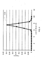
- FIG. 6 shows a plotted ventilation histogram 110-H determined from the data of the ventilation signal 530V for the night.
- analysis of the histogram may detect that the patient's ventilation has a bi-modal distribution. In some embodiments, this may be determined by detecting the existence of two peaks. If an evaluation of the ventilation value or interval attributable to either peak is indicative of low ventilation, the analysis may be taken as an indication of an incident of hypoventilation. In the example of FIG. 6 , one peak is at approximately 5 liters per minute and the other peak is approximately 9 liters per minute. The peak at 5 liters per minute may be taken as an indicator of hypoventilation.
- some embodiments of the ventilation assessment may partition ventilation data based on detection of leak.
- a ventilation assessment device of the present technology may be combined with, or receive leak data from, a leak detector, such as a mouth leak detector.
- the mouth leak detector may be implemented by one or more of the methodologies disclosed in U.S. Provisional Patent Application No. 61/369,247, filed on July 30, 2010 .
- a ventilation histogram may be evaluated. For example, a histogram may be based on ventilation values taken only from periods of treatment during which there is no leak. Thus, the histogram assessment may disregard ventilation values that are contemporaneous with periods of leak.
- another leak-related histogram may be computed based on ventilation values taken only from periods of treatment during which a mouth leak is detected.
- the leak-related- histogram may then be evaluated to rule out a potential indication of hypoventilation that is based on the data of the more complete ventilation histogram that includes ventilation values from periods with and without leak.
- some embodiments of the ventilation assessment may partition ventilation data based on detection of ventilatory instability.
- a ventilation assessment device of the present technology may be combined with, or receive ventilatory stability data from, a ventilatory stability detector.
- the ventilatory stability detector may be implemented by one or more of the methodologies, such as the methodology that derives a sleep stability measure, awake state, periodic breathing, arousals or other events or measures therein that may serve to imply stability, or lack thereof, for patient ventilation, as disclosed in U.S. Provisional Patent Application No.
- a ventilation histogram may be evaluated. For example, a histogram may be based on ventilation values taken from periods of treatment during which the ventilatory stability detector suggests that the ventilation levels are stable and therefore will not corrupt the formation of the histogram.
- the ventilator stability index may be calculated as a rolling variance of another respiratory feature which is related to ventilation.
- An example of such a feature may be the inspiratory tidal volume.
- Others include expiratory tidal volume, whole breath tidal volume (e.g., an integration of the absolute value of a flow signal that is divided by breath length).
- the ventilation histogram may then be formed from ventilation values taken during treatment when the rolling variance of any of these features is below a predetermined threshold.
- calculation of the ventilation histogram may be performed in accordance with both a leak detector and a ventilation stability detector.
- the resulting histogram would contain ventilation values during treatment periods characterized by ventilatory stability and an absence of leak.
- the present ventilation assessment technology may be implemented with a respiratory treatment apparatus 802, such as a CPAP device, or other respiratory treatment apparatus that provides pressurized breathable gas to a patient. (e.g., constant CPAP or bi-level CPAP).
- a respiratory treatment apparatus 802 such as a CPAP device, or other respiratory treatment apparatus that provides pressurized breathable gas to a patient.
- a respiratory treatment apparatus 802 such as a CPAP device, or other respiratory treatment apparatus that provides pressurized breathable gas to a patient.
- a respiratory treatment apparatus 802 such as a CPAP device, or other respiratory treatment apparatus that provides pressurized breathable gas to a patient.
- a respiratory treatment apparatus such as a CPAP device, or other respiratory treatment apparatus that provides pressurized breathable gas to a patient.
- Such an apparatus may include a flow generator such as a servo-controlled blower 809.
- the blower 809 can typically include an air inlet and impeller driven by a motor (not shown).
- the respiratory treatment apparatus 802 will also typically include, or be connectable to, a patient interface that may comprise an air delivery conduit 807 and a mask 808 to carry a flow of air or breathable gas to and/or from a patient.
- a patient interface may comprise an air delivery conduit 807 and a mask 808 to carry a flow of air or breathable gas to and/or from a patient.
- the mask may include a vent to provide an intentional leak.
- the apparatus 802 also may include, or be connectable to, one or more sensors 806, such as a pressure sensor, flow sensor and/or an oximetry sensor.
- the pressure sensor such as a pressure transducer
- the flow sensor may measure the pressure generated by the blower 809 and generate a pressure signal p(t) indicative of the measurements of pressure.
- the flow sensor generates a signal representative of the patient's respiratory flow. For example, flow proximate to the patient interface 808 or a sense tube (not shown) or flow proximate to the blower 809 may be measured using a pneumotachograph and differential pressure transducer or similar device such as one employing a bundle of tubes or ducts to derive a flow signal f(t).
- the oximetry sensor may be a pulse oximeter to generate oximetry signals O 2 (t) indicative of blood gas saturation levels, such as oxygen saturation.
- O 2 (t) indicative of blood gas saturation levels
- Other sensors may be utilized to generate data indicative of flow, pressure or oximetry for the purposes of the methodologies of the apparatus 802.
- a controller 804 may generate blower control signals. For example, the controller may generate a desired pressure set point and servo-control the speed of the blower to meet the set point by comparing the set point with the measured condition of the pressure sensor. Thus, the controller 804 may make controlled changes to the pressure delivered to the patient interface by the blower 809. Typically, such settings may be made to set a desired treatment pressure, to synchronize a treatment with patient respiration or to support the patient's respiration and may be made in conjunction with a detection of a state of a patient respiration such as by analysis of the flow signals in conjunction with control parameters such as trigger and cycling thresholds.
- changes to pressure may be implemented by controlling an exhaust with a mechanical release valve (not shown) to increase or decrease the exhaust while maintaining a relatively constant blower speed.
- the controller 804 may implement the present ventilation assessment methodologies described in more detail herein.
- the controller 804 may include one or more processors programmed to implement particular methodologies or algorithms described in more detail herein.
- the controller may include integrated chips, a memory and/or other control instruction, data or information storage medium.
- programmed instructions encompassing such a control methodology may be coded on integrated chips in the memory of the device.
- Such instructions may also or alternatively be loaded as software or firmware using an appropriate data storage medium.
- the controller detects or may score hypoventilation or hyperventilation events based on the evaluation of the ventilation histogram as discussed herein and modify pressure control parameters for the respiratory treatment based on the detection of such events. For example, if one or more of hypoventilation events have been detected, the controller may increase pressure or automatically change a treatment protocol to increase ventilation such as by switching to a bi-level PAP mode from a more constant CPAP mode. Similarly, if one or more of hyperventilation events have been detected, the controller may decrease pressure or automatically change a treatment protocol to decrease ventilation such as by switching from a bi-level CPAP mode to a more constant CPAP mode.
- the controller may generate warning or informational messages based on the ventilation assessment of the ventilation histogram.
- the controller may display (e.g., on an LCD or other display device of the apparatus) and/or transmit (e.g., via wired or wireless communication or other data transfer) messages concerning the detection of hypoventilation or hyperventilation.
- the controller may also generate messages with the data of the ventilation histogram.
- the controller may also generate message to suggest further testing. For example, based on the evaluation of the ventilation histogram, such as a detection of hypoventilation, the controller may generate a message to suggest or request that the patient begin using a pulse oximeter sensor in a subsequent treatment session with the respiratory treatment apparatus.
- the controller may then initiate analysis of pulse oximetry data in a subsequent treatment session based on the analysis of the ventilation histogram from the prior session.
- the data of the pulse oximetry in a subsequent session may then be analyzed by the controller to confirm occurrence of ventilation inadequacy (e.g., hypoventilation) previously detected by analysis of the ventilation histogram.
- Further messages may then be generated by the device after analysis of the oximetry data to identify to the patient and/or physician that other treatment may be necessary due to over ventilation or under ventilation or may identify that ventilation is acceptable.
- control parameters or messages from the respiratory treatment apparatus may also be made or suggested in accordance with the detection of the hypoventilation or hyperventilation based on the ventilation histogram evaluation.
- any or all of the, following steps or procedures may be implemented by the controller.
- V LP 0.5 ⁇ Qresp
- LP is, for example, a single pole low pass filter with a time constant of about 180 seconds
- Evaluate platykurtic distributions (e.g., kurtosis ⁇ 1). This will typically indicate a flatter central portion (e.g., less "peakedness").
- the threshold here may be set to 1.
- a smaller Kurtosis value may be taken to mean that the histogram will have a smaller peak(s) and larger tails. This may typically be seen in a ventilation histogram of a patient with hypoventilation.
- a standard normal distribution will have a kurtosis of 3 and a bi-modal distribution will have larger tails and a flatter peak in most cases.
- the distribution may be evaluated to determine bimodality by using an M-shape detection algorithm.
- M-shape detection algorithm This can serve as a metric for detecting the presence of bimodality.
- One such method is described in International Patent Application No. PCT/AU2008/000647, filed on May 9, 2008 .
- a metric such as an Apnea Hypopnea Index
- calculated probability that the session of night flow data is indicative of someone experiencing hypoventilation.
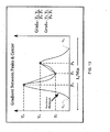
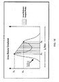
- steps or procedures may also be implemented in addition, or instead of, the ones described above. These steps or procedures, which may be controlled operations of one or more processors or controllers, may be considered with the illustrated graphs of Figs. 10 through 17 : a. Calculate a histogram of the patient ventilation estimate over the duration of the night or session, such as one when there is little or NO leak and ventilatory stability exists. b. Calculate the number of peaks of the histogram and their heights, such as the example heights Y A and Y B illustrated in Fig. 10 , using a peak detector. c.
- any other function which can transform numbers associated with the distance between the peaks, from real number space into a probability space such as a 0 to 1 space can be used.
- G(X) probability of occurrence of hypoventilation
- the X coordinate of the lower of the peaks indicates the ventilation level at which the lower peak is occurring and can be taken as the level of hypoventilation.
- the amplitude of the peak e.g., Y A ) indicates the number of 3-minute periods during which the particular ventilation has been detected and, thus, can be used to estimate the overall duration during which the given ventilation has been measured.
- a processor may be configured to calculate the estimated duration with the example formula illustrated in FIG. 10 .
- a metric or probability may be reported (e.g., recorded or generated as output) to provide an indication of the likelihood that the session of night flow data is indicative of someone experiencing hypoventilation.
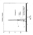
- Fig. 16 shows an example of a substantially single-peaked histogram for which the probability classification system based on function G(x) of Table T returns a 'low' probability of 0.2. Such a low probability may be taken as an indication that presence of hypoventilation is unlikely.
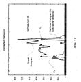
- Fig. 17 shows an example of a bimodal histogram for which the probability classification system has returned a 'high' probability of 0.85. This may be taken as an indication that the presence of hypoventilation is highly likely.
- the processor may generate the metric and/or the histogram graph to provide the indication of hypoventilation, such as the hypoventilation probability value, the hypoventilation value and/or the level of hypoventilation in association with the hypoventilation probability value.
- the reported results may then be implemented for providing an indication of further treatment. For example, a positive indication of hypoventilation may be taken as a suggestion for a night or several nights SpO 2 monitoring.
- a processor may evaluate the reported probability by a comparison of the probability with one or more thresholds. Based on the comparison(s), a message may be generated to suggest additional testing (e.g., further SpO 2 monitoring) or some other treatment.
- such a comparison may serve as a trigger to control further testing or treatment, such as a change in control of a generated pressure treatment with a respiratory treatment apparatus (e.g., an increase in pressure support (PS) ventilation or an initiation of pressure support ventilation so as to servo control a measure of ventilation to satisfy a target ventilation) or a further evaluation.
- a respiratory treatment apparatus e.g., an increase in pressure support (PS) ventilation or an initiation of pressure support ventilation so as to servo control a measure of ventilation to satisfy a target ventilation
- the apparatus 102 may also be configured to evaluate blood gas, such as with an oximeter that may be controlled with a processor of the apparatus.
- the processor may, based on the evaluation of the histogram, confirm that hypoventilation is present by controlling an analysis of SpO 2 data.
- the processor may be configured to implement typical "rules" for sleep-related hypoventilation/hypoxaemia detection from blood gas.
- the processor may then generate, as output, the determinations based on each or both of the ventilation histogram evaluation and the blood gas evaluation.
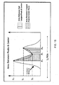
- one or more of the following procedures or steps may also be implemented by one or more processors :
- a midpoint such as the center of the histogram, which may be the midpoint P C between the two extreme points (TL1 and TL2) of the tails of the histogram, as (shown in Fig. 13 );
- i. Convert the gradient between the two largest peaks into a probability space, such as a 0 to 1 space, with a transformation function. If the gradient is either highly positive or highly negative, it may serve as an indication that the peak locations are too close or the smaller peak is too small. This may be seen in a histogram of a patient without hypoventilation and so the probability of hypoventilation associated with highly positive or highly negative gradient can be close to 0 according to the transformation function. The probability will get closer to 1 as the gradients get closer to 0 according to such a function.
- j. Convert the gradient between the largest peak & center point into a probability space, such as a 0 to 1 probability space, using a transformation function. If the gradient is either highly positive or highly negative, it may serve as an indication that the peak locations are too close or the smaller peak is too small. This may be seen in a histogram of a patient without hypoventilation and in such a case, the probability of hypoventilation can be close to 0 according to the transformation function. The probability will get closer to 1 as the gradients get closer to 0 according to such a function.
- k Convert the gradient between the 2 nd largest peak & center point into a probability space, such as the 0 to 1 probability space, using a transformation function. If the gradient is either highly positive or highly negative, it may serve as an indication that the peak locations are too close or the smaller peak is too small. This may be seen in a histogram of a patient without hypoventilation and so the hypoventilation probability can be close to 0 according to the transformation function. The probability can get closer to 1 as the gradients get closer to 0 with such a function.
- m Convert the area between the largest peak and the center point into a probability space, such as a 0 to 1 probability space, using a transformation function. If the area is sufficiently large, then it may serve as an indication of the peaks being sufficiently far apart. For such increasingly large area cases, the probability can approach 1 according to such a probability function.' For smaller areas as they decrease, the probability can approach 0 with such a function.
- n Convert a shape feature into a probability space, such as a probability space between 0 and 1, using a transformation function.
- a transformation function will depend on the nature of the approximation function used to calculate the shape feature.
- kurtosis and skewness into a probability space, such as a 0 to 1 probability space, using a transformation function.
- a positive skewness may be taken as an indication of a higher chance of hypoventilation occurring and so the transformation probability can be closer to 1 for positive values.
- Negative skewness values may indicate a lower chance of hypoventilation occurring and so the hypoventilation probability maybe closer to 0 according to such a function.
- a higher kurtosis may be taken as an indication of a higher chance of hypoventilation occurring and so the transformation probability can be closer to 1 according to such a function.
- Lower kurtosis values can be taken as an indication of a lower chance of hypoventilation occurring and so the hypoventilation probability may approach 0 according so such a function.
- Such features may include:
- a processor may be implemented to calculate a hypoventilation probability, such as with a classification algorithm. Some or all of the above features may be evaluated. Weighting coefficients may also be implemented. In some such cases, the set of transformation probabilities or weighted probabilities may be compared to set of thresholds to assess the overall likelihood of hypoventilation given the values of the transformation probabilities. In one particular embodiment, a linear classifier could be implemented by a processor to calculate the overall hypoventilation probability. However other classification methods which can utilize the above mentioned features such as Bayesian Classification can be employed to calculate a final hypoventilation probability. As with previous embodiments, the hypoventilation probability may be reported as output. An evaluation of the value may be performed, such as by comparison with one or more thresholds, to control a further treatment or evaluation or generation of a message as previously described.
- the ventilation assessment device 902 or general purpose computer may include one or more processors 908.
- the device may also include a display interface 910 to output ventilation detection reports (e.g., ventilation histogram data, hypoventilation event data, hyperventilation event data, skewness indices, kurtosis indices, and/or ventilation values etc.), results or graphs (e.g., plotted ventilation histograms and/or signal traces as illustrated in the examples of FIGs. 3 , 4 , 5 , 6 and 7 ) as described herein such as on a monitor or LCD panel.
- ventilation detection reports e.g., ventilation histogram data, hypoventilation event data, hyperventilation event data, skewness indices, kurtosis indices, and/or ventilation values etc.
- results or graphs e.g., plotted ventilation histograms and/or signal traces as illustrated in the examples of FIGs. 3 , 4 , 5 , 6 and 7 ) as described here
- a user control/input interface 912 for example, for a keyboard, touch panel, control buttons, mouse etc. may also be provided to activate the methodologies described herein.
- the device may also include a sensor or data interface 914, such as a bus, for receiving/transmitting data such as programming instructions, oximetery data, flow data, pressure data, ventilation value data, ventilation histogram data etc.
- the device may also typically include a memory/data storage components containing control instructions of the aforementioned methodologies (e.g., FIG. 2 ). These may include processor control instructions for flow signal processing (e.g., pre-processing methods, filters) at 922 as discussed in more detail herein.
- processor control instructions for ventilation measure determination e.g., partitioning, filtering and sampling etc.
- processor control instructions for ventilation histogram determination or associated data evaluation e.g., peak detection, peak counting, feature analysis, transformation functions, kurtosis index determination and thresholding, skewness index determination and thresholding, bimodality detection, leak evaluation, hypoventilation and/or hyperventilation scoring etc.
- They may also include stored data 928 for these methodologies such as ventilation data, flow data, histograms, kurtosis indices, skewness indices, peaks, peak counts, gradients, transformation probabilities, reports and graphs, etc.
- processor control instructions for controlling responses to histogram evaluation(s) at 930 such as warning or information message generation, pressure treatment control changes, further testing control, etc.
- the processor control instructions and data for controlling the above described methodologies may be contained in a computer readable recording medium as software for use by a general purpose computer so that the general purpose computer may serve as a specific purpose computer according to any of the methodologies discussed herein upon loading the software into the general purpose computer.
- the special purpose computer may not need to be configured to control pressure treatment or measure pressure or flow data. Rather, the computer may merely access such data, that may optionally be transferred from a respiratory treatment apparatus. The computer may then perform the ventilation assessment methodologies described herein such as the histogram determination and analysis based on the transferred data and may generate warning or informational messages based thereon.
Claims (16)
- Appareil d'estimation de ventilation comprenant :un dispositif de commande (104) ayant au moins un processeur pour accéder à des données représentant un flux mesuré d'un gaz respirable attribuable à la respiration d'un patient, le dispositif de commande (104) étant en outre configuré pour(a) dériver des mesures de ventilation à partir des données représentant le flux mesuré de gaz respirable, et(b) déterminer un histogramme sur la base des mesures de ventilation,et caractérisé en ce que le dispositif de commande est en outre configuré pour (c) évaluer l'histogramme dans le processeur pour détecter une occurrence de d'hypoventilation ou d'hyperventilation, et
(d) (1) émettre, sur la base de l'évaluation, une indication de l'occurrence de d'hypoventilation ou d'hyperventilation et/ou (2) changer, sur la base de l'évaluation, un paramètre de commande de pression ou un protocole de soins d'un appareil de soins respiratoire,dans lequel l'évaluation de l'histogramme comprend la détermination d'une ou plusieurs des caractéristiques suivantes : un nombre de pics de l'histogramme, un gradient entre les deux pics les plus élevés de l'histogramme, un gradient entre le premier pic le plus élevé et un point central de l'histogramme, un gradient entre le second pic le plus élevé et un point central de l'histogramme, une zone entre les deux pics les plus élevés de l'histogramme, une zone entre le premier pic le plus élevé et un point central de l'histogramme, une zone entre le second pic le plus élevé et un point central de l'histogramme, une caractéristique de forme de l'histogramme, une valeur d'aplatissement basée sur l'histogramme, et une valeur de dissymétrie basée sur l'histogramme. - Appareil selon la revendication 1, dans lequel le dispositif de commande est en outre configuré pour afficher un graphique de l'histogramme sur un dispositif d'affichage visuel.
- Appareil selon la revendication 1 ou 2, dans lequel l'histogramme représente une répartition de fréquence de valeurs de ventilation prises au cours d'une session de soins, chaque valeur de ventilation comprenant une mesure de volume sur un intervalle de temps, l'intervalle de temps étant plus court que le temps de la session de soins.
- Appareil selon la revendication 3, dans lequel l'intervalle de temps est de l'ordre d'une minute et le temps de la session de soins est de l'ordre de plusieurs heures.
- Appareil selon l'une quelconque des revendications 1 à 4, dans lequel le dispositif de commande est en outre configuré pour :traiter des données associées à l'histogramme pour calculer la valeur de dissymétrie sous la forme d'un indice appelé indice de dissymétrie ;comparer l'indice de dissymétrie à un seuil ; etindiquer une occurrence d'hypoventilation sur la base de la comparaison.
- Appareil selon l'une quelconque des revendications 1 à 5 dans lequel le dispositif de commande est en outre configuré pour :traiter des données associées à l'histogramme pour détecter le nombre de pics de l'histogramme ; etindiquer une présence ou une absence d'hypoventilation sur la base du nombre de pics détectés.
- Appareil selon l'une quelconque des revendications 1 à 6 dans lequel le dispositif de commande est en outre configuré pour :traiter des données associées à l'histogramme pour déterminer la valeur d'aplatissement sous la forme d'un indice appelé indice d'aplatissement ;comparer l'indice d'aplatissement à un seuil ; etindiquer une présence ou une absence d'hypoventilation sur la base de la comparaison.
- Appareil selon l'une quelconque des revendications 1 à 7, comprenant en outre un capteur de flux, et dans lequel le dispositif de commande est en outre configuré pour commander la mesure du flux de gaz respirable avec le capteur de flux.
- Appareil selon la revendication 8, comprenant en outre :
un générateur de flux configuré pour produire un gaz respirable pour un patient à une pression supérieure à la pression atmosphérique ; dans lequel le dispositif de commande est en outre configuré pour commander le générateur de flux pour produire le gaz respirable selon un régime de thérapie par pression sur la base d'une estimation d'un ou plusieurs éléments quelconques parmi (a) l'histogramme, (b) le nombre de pics de l'histogramme, (c) la valeur d'aplatissement qui est un indice déterminé à partir de données associées à l'histogramme et (d) la valeur de dissymétrie qui est un indice déterminé à partir de données associées à l'histogramme. - Appareil selon l'une quelconque des revendications 1 à 9, dans lequel le dispositif de commande est configuré pour traiter des données représentant l'histogramme pour générer un indicateur d'hypoventilation, l'indicateur d'hypoventilation représentant une occurrence d'un événement d'hypoventilation, dans lequel de préférence l'indicateur d'hypoventilation comprend une valeur de probabilité.
- Appareil selon la revendication 10 dans lequel le dispositif de commande est configuré pour détecter des pics de l'histogramme, dans lequel de préférence le dispositif de commande est configuré pour calculer une distance entre les pics de l'histogramme et transformer la distance en un espace de probabilité.
- Appareil selon la revendication 11, dans lequel le dispositif de commande est configuré pour calculer le gradient entre les pics de l'histogramme, dans lequel,
de préférence, le dispositif de commande est configuré pour calculer une zone par rapport au gradient entre les pics et transformer la zone en un espace de probabilité. - Appareil selon l'une quelconque des revendications 10 et 11, dans lequel le dispositif de commande est configuré pour calculer un ensemble de caractéristiques de l'histogramme et pour générer l'indicateur sur la base d'une évaluation de l'ensemble de caractéristiques, dans lequel
de préférence, l'ensemble de caractéristiques comprend deux des caractéristiques suivantes ou plus : le gradient entre les deux pics les plus élevés, le gradient entre le premier pic le plus élevé et le point central, le gradient entre le second pic le plus élevé et le point central, la zone entre les deux pics les plus élevés, la zone entre le premier pic le plus élevé et le point central, la zone entre le second pic le plus élevé et le point central, la caractéristique de forme, la valeur d'aplatissement et la valeur de dissymétrie. - Appareil selon l'une quelconque des revendications 1 à 13, dans lequel le dispositif de commande est configuré pour déterminer une mesure de fuite et pour distinguer les mesures de ventilation pour l'histogramme sur la base de la mesure de fuite.
- Appareil selon l'une quelconque des revendications 1 à 14, dans lequel le dispositif de commande est configuré pour déterminer une mesure de stabilité de ventilation et pour distinguer les mesures de ventilation pour l'histogramme sur la base de la mesure de stabilité de ventilation, dans lequel
de préférence, le dispositif de commande détermine la mesure de stabilité de ventilation en détectant l'un quelconque d'un ou plusieurs parmi une période d'éveil, un événement d'apnée, un événement de respiration périodique et un événement d'excitation. - Appareil selon l'une quelconque des revendications 1 à 9, 14 et 15 dans lequel le dispositif de commande est configuré pour traiter des données représentant l'histogramme pour générer un indicateur d'hyperventilation, l'indicateur d'hyperventilation représentant une occurrence d'un événement d'hyperventilation.
Applications Claiming Priority (2)
| Application Number | Priority Date | Filing Date | Title |
|---|---|---|---|
| US201161466560P | 2011-03-23 | 2011-03-23 | |
| PCT/AU2012/000270 WO2012126041A1 (fr) | 2011-03-23 | 2012-03-15 | Détection de l'autonomie respiratoire |
Publications (3)
| Publication Number | Publication Date |
|---|---|
| EP2688466A1 EP2688466A1 (fr) | 2014-01-29 |
| EP2688466A4 EP2688466A4 (fr) | 2014-11-12 |
| EP2688466B1 true EP2688466B1 (fr) | 2021-11-17 |
Family
ID=46878525
Family Applications (1)
| Application Number | Title | Priority Date | Filing Date |
|---|---|---|---|
| EP12761355.2A Active EP2688466B1 (fr) | 2011-03-23 | 2012-03-15 | Détection de l'autonomie respiratoire |
Country Status (6)
| Country | Link |
|---|---|
| US (1) | US10342939B2 (fr) |
| EP (1) | EP2688466B1 (fr) |
| JP (1) | JP6002747B2 (fr) |
| CN (1) | CN103501690B (fr) |
| AU (1) | AU2012231762B2 (fr) |
| WO (1) | WO2012126041A1 (fr) |
Families Citing this family (31)
| Publication number | Priority date | Publication date | Assignee | Title |
|---|---|---|---|---|
| US9862892B2 (en) | 2012-02-21 | 2018-01-09 | Battelle Memorial Institute | Heavy fossil hydrocarbon conversion and upgrading using radio-frequency or microwave energy |
| ES2906605T3 (es) | 2012-04-05 | 2022-04-19 | Fisher & Paykel Healthcare Ltd | Aparato de ayuda respiratoria |
| JP6620016B2 (ja) * | 2012-04-24 | 2019-12-11 | コーニンクレッカ フィリップス エヌ ヴェKoninklijke Philips N.V. | ポータブル手持ち用圧力支援システム及び方法 |
| US9839756B2 (en) | 2012-11-27 | 2017-12-12 | Resmed Limited | Methods and apparatus for ionization therapy |
| JP6226523B2 (ja) * | 2012-12-28 | 2017-11-08 | キヤノン株式会社 | 被検体情報取得装置、表示方法、およびデータ処理装置 |
| US10493223B2 (en) * | 2013-06-19 | 2019-12-03 | Koninklijke Philips N.V. | Determining of subject zero flow using cluster analysis |
| CN110393839B (zh) | 2014-05-27 | 2023-03-24 | 费雪派克医疗保健有限公司 | 用于医疗装置的气体混合和测量 |
| US9931483B2 (en) * | 2014-05-28 | 2018-04-03 | Devilbiss Healtcare Llc | Detection of periodic breathing during CPAP therapy |
| NZ750402A (en) * | 2014-06-10 | 2020-08-28 | ResMed Pty Ltd | Method and apparatus for treatment of respiratory disorders |
| US10112022B2 (en) | 2014-09-18 | 2018-10-30 | Devilbiss Healthcare Llc | Method for detecting an inspiratory flow limitation during sleep-disordered breathing |
| JP6574484B2 (ja) * | 2014-12-30 | 2019-09-11 | コーニンクレッカ フィリップス エヌ ヴェKoninklijke Philips N.V. | 補助酸素の検出を伴うカプノメトリシステム及びその動作方法 |
| WO2016108121A1 (fr) * | 2014-12-31 | 2016-07-07 | Koninklijke Philips N.V. | Système pour réaliser une analyse d'histogramme de signaux de capnographie basés sur le temps, et son procédé de fonctionnement |
| US11497870B2 (en) * | 2015-02-24 | 2022-11-15 | Somnetics International, Inc. | Systems and methods for estimating flow in positive airway pressure therapy |
| US10245406B2 (en) | 2015-03-24 | 2019-04-02 | Ventec Life Systems, Inc. | Ventilator with integrated oxygen production |
| US11247015B2 (en) | 2015-03-24 | 2022-02-15 | Ventec Life Systems, Inc. | Ventilator with integrated oxygen production |
| KR101808691B1 (ko) * | 2015-06-25 | 2017-12-14 | 충북대학교 산학협력단 | 중환자 호흡 모니터링 시스템 및 방법 |
| US20180228399A1 (en) * | 2015-08-11 | 2018-08-16 | Koninklijke Philips N.V. | Capnography with decision support system architecture |
| US11266801B2 (en) * | 2015-10-09 | 2022-03-08 | University Of Utah Research Foundation | Ventilation devices and systems and methods of using same |
| WO2017068464A1 (fr) * | 2015-10-19 | 2017-04-27 | Koninklijke Philips N.V. | Dispositif de détection d'anomalie et procédé pour l'estimation de paramètres de mécanique respiratoire |
| US11666720B2 (en) | 2015-12-02 | 2023-06-06 | Fisher & Paykel Healthcare Limited | Flow path sensing for flow therapy apparatus |
| CN105457135B (zh) * | 2015-12-28 | 2018-12-28 | 湖南明康中锦医疗科技发展有限公司 | 呼吸机压力调整方法、装置及呼吸机 |
| ITUB20160614A1 (it) * | 2016-02-10 | 2017-08-10 | Elbi Int Spa | Assieme di trasduttore di pressione e dispositivo antiallagamento per un apparecchio, ad esempio una macchina lavatrice. |
| WO2017187391A1 (fr) * | 2016-04-29 | 2017-11-02 | Fisher & Paykel Healthcare Limited | Système de détermination de la perméabilité des voies respiratoires |
| US10773049B2 (en) | 2016-06-21 | 2020-09-15 | Ventec Life Systems, Inc. | Cough-assist systems with humidifier bypass |
| JP7313341B2 (ja) | 2017-09-28 | 2023-07-24 | コーニンクレッカ フィリップス エヌ ヴェ | 圧力支援治療中に患者の脳卒中を検出するシステム及び方法 |
| US20220040428A1 (en) * | 2017-10-07 | 2022-02-10 | University Of Utah Research Foundation | Ventilation Devices and Systems and Methods of Using Same |
| DE102017011625A1 (de) * | 2017-12-15 | 2019-07-18 | Drägerwerk AG & Co. KGaA | Verfahren, Computerprogramm, Vorrichtung und Beatmungssystem zur Detektion eines Lecks in einem Patientengasmodul |
| EP3781244A4 (fr) | 2018-05-13 | 2022-01-19 | Ventec Life Systems, Inc. | Système portable de ventilateur médical utilisant des concentrateurs portables d'oxygène |
| US10866006B2 (en) * | 2018-06-25 | 2020-12-15 | Dell Products L.P. | Systems and methods for fan typing and anomaly detection |
| DE102018126553A1 (de) * | 2018-10-24 | 2020-04-30 | Dürr Dental SE | Sensoreneinheit und Druckluftkompressorsystem mit einer solchen |
| DE102021000317A1 (de) | 2020-02-14 | 2021-08-19 | Löwenstein Medical Technology S.A. | Überwachungssystem zur Erkennung von Leckagen während einer Beatmung und Verfahren |
Family Cites Families (20)
| Publication number | Priority date | Publication date | Assignee | Title |
|---|---|---|---|---|
| US5335654A (en) * | 1992-05-07 | 1994-08-09 | New York University | Method and apparatus for continuous adjustment of positive airway pressure for treating obstructive sleep apnea |
| EP2113196A3 (fr) * | 1993-11-05 | 2009-12-23 | ResMed Limited | Contrôle de traitement CPAP |
| US6273088B1 (en) * | 1997-06-13 | 2001-08-14 | Sierra Biotechnology Company Lc | Ventilator biofeedback for weaning and assistance |
| US6099481A (en) * | 1997-11-03 | 2000-08-08 | Ntc Technology, Inc. | Respiratory profile parameter determination method and apparatus |
| DE10014427A1 (de) * | 2000-03-24 | 2001-10-04 | Weinmann G Geraete Med | Verfahren zur Steuerung eines Beatmungsgerätes sowie Vorrichtung zur Überwachung |
| US6814073B2 (en) | 2000-08-29 | 2004-11-09 | Resmed Limited | Respiratory apparatus with improved flow-flattening detection |
| DE10103973A1 (de) * | 2001-01-30 | 2002-08-01 | Peter L Kowallik | Verfahren und Vorrichtung zur Schlafüberwachung |
| US7168429B2 (en) | 2001-10-12 | 2007-01-30 | Ric Investments, Llc | Auto-titration pressure support system and method of using same |
| US7938114B2 (en) * | 2001-10-12 | 2011-05-10 | Ric Investments Llc | Auto-titration bi-level pressure support system and method of using same |
| US6881192B1 (en) * | 2002-06-12 | 2005-04-19 | Pacesetter, Inc. | Measurement of sleep apnea duration and evaluation of response therapies using duration metrics |
| EP1556834A4 (fr) * | 2002-10-03 | 2009-04-01 | Scott Lab Inc | Systemes et procedes assurant la fusion des capteurs |
| US8467876B2 (en) * | 2003-10-15 | 2013-06-18 | Rmx, Llc | Breathing disorder detection and therapy delivery device and method |
| EP2208504B1 (fr) * | 2003-11-26 | 2012-12-26 | ResMed Limited | Appareil pour le contrôle systématique de l'assistance respiratoire en présence d'une insuffisance respiratoire |
| US7717110B2 (en) | 2004-10-01 | 2010-05-18 | Ric Investments, Llc | Method and apparatus for treating Cheyne-Stokes respiration |
| US20080269583A1 (en) * | 2005-02-07 | 2008-10-30 | Widemed Ltd. | Detection and Monitoring of Stress Events During Sleep |
| US20060282002A1 (en) | 2005-06-10 | 2006-12-14 | Treatyou Medical Technology Co. | Respiratory testing system |
| US8992436B2 (en) | 2005-09-16 | 2015-03-31 | Cardiac Pacemakers, Inc. | Respiration monitoring using respiration rate variability |
| US7479114B2 (en) | 2005-12-01 | 2009-01-20 | Cardiac Pacemakers, Inc. | Determining blood gas saturation based on measured parameter of respiration |
| US7810497B2 (en) * | 2006-03-20 | 2010-10-12 | Ric Investments, Llc | Ventilatory control system |
| CN109999289B (zh) * | 2007-05-11 | 2021-09-24 | 瑞思迈私人有限公司 | 针对流量限制检测的自动控制 |
-
2012
- 2012-03-15 CN CN201280010487.0A patent/CN103501690B/zh active Active
- 2012-03-15 AU AU2012231762A patent/AU2012231762B2/en not_active Ceased
- 2012-03-15 WO PCT/AU2012/000270 patent/WO2012126041A1/fr active Application Filing
- 2012-03-15 US US14/006,772 patent/US10342939B2/en active Active
- 2012-03-15 EP EP12761355.2A patent/EP2688466B1/fr active Active
- 2012-03-15 JP JP2014500202A patent/JP6002747B2/ja active Active
Non-Patent Citations (1)
| Title |
|---|
| None * |
Also Published As
| Publication number | Publication date |
|---|---|
| EP2688466A4 (fr) | 2014-11-12 |
| US20140007878A1 (en) | 2014-01-09 |
| CN103501690B (zh) | 2016-10-26 |
| AU2012231762B2 (en) | 2015-06-18 |
| US10342939B2 (en) | 2019-07-09 |
| JP6002747B2 (ja) | 2016-10-05 |
| CN103501690A (zh) | 2014-01-08 |
| NZ612813A (en) | 2015-04-24 |
| JP2014519856A (ja) | 2014-08-21 |
| WO2012126041A1 (fr) | 2012-09-27 |
| AU2012231762A1 (en) | 2013-07-04 |
| EP2688466A1 (fr) | 2014-01-29 |
Similar Documents
| Publication | Publication Date | Title |
|---|---|---|
| EP2688466B1 (fr) | Détection de l'autonomie respiratoire | |
| JP7317920B2 (ja) | 漏れ検出を用いた方法及びデバイス | |
| JP6220369B2 (ja) | 呼吸低下を検出するための方法および装置 | |
| AU2008251011B2 (en) | Automated control for detection of flow limitation | |
| WO2011006199A1 (fr) | Détection d'état de sommeil | |
| NZ612813B2 (en) | Detection of ventilation sufficiency | |
| AU2013267068B2 (en) | Detection of Sleep Condition | |
| AU2015201732A1 (en) | Methods and Devices with Leak Detection |
Legal Events
| Date | Code | Title | Description |
|---|---|---|---|
| PUAI | Public reference made under article 153(3) epc to a published international application that has entered the european phase |
Free format text: ORIGINAL CODE: 0009012 |
|
| 17P | Request for examination filed |
Effective date: 20131016 |
|
| AK | Designated contracting states |
Kind code of ref document: A1 Designated state(s): AL AT BE BG CH CY CZ DE DK EE ES FI FR GB GR HR HU IE IS IT LI LT LU LV MC MK MT NL NO PL PT RO RS SE SI SK SM TR |
|
| DAX | Request for extension of the european patent (deleted) | ||
| A4 | Supplementary search report drawn up and despatched |
Effective date: 20141013 |
|
| RIC1 | Information provided on ipc code assigned before grant |
Ipc: A61M 16/00 20060101ALI20141007BHEP Ipc: A61B 5/00 20060101AFI20141007BHEP |
|
| STAA | Information on the status of an ep patent application or granted ep patent |
Free format text: STATUS: EXAMINATION IS IN PROGRESS |
|
| 17Q | First examination report despatched |
Effective date: 20171124 |
|
| RAP1 | Party data changed (applicant data changed or rights of an application transferred) |
Owner name: RESMED PTY LTD |
|
| GRAP | Despatch of communication of intention to grant a patent |
Free format text: ORIGINAL CODE: EPIDOSNIGR1 |
|
| STAA | Information on the status of an ep patent application or granted ep patent |
Free format text: STATUS: GRANT OF PATENT IS INTENDED |
|
| INTG | Intention to grant announced |
Effective date: 20210104 |
|
| INTG | Intention to grant announced |
Effective date: 20210113 |
|
| GRAJ | Information related to disapproval of communication of intention to grant by the applicant or resumption of examination proceedings by the epo deleted |
Free format text: ORIGINAL CODE: EPIDOSDIGR1 |
|
| STAA | Information on the status of an ep patent application or granted ep patent |
Free format text: STATUS: EXAMINATION IS IN PROGRESS |
|
| GRAP | Despatch of communication of intention to grant a patent |
Free format text: ORIGINAL CODE: EPIDOSNIGR1 |
|
| STAA | Information on the status of an ep patent application or granted ep patent |
Free format text: STATUS: GRANT OF PATENT IS INTENDED |
|
| INTC | Intention to grant announced (deleted) | ||
| INTG | Intention to grant announced |
Effective date: 20210601 |
|
| GRAS | Grant fee paid |
Free format text: ORIGINAL CODE: EPIDOSNIGR3 |
|
| GRAA | (expected) grant |
Free format text: ORIGINAL CODE: 0009210 |
|
| STAA | Information on the status of an ep patent application or granted ep patent |
Free format text: STATUS: THE PATENT HAS BEEN GRANTED |
|
| AK | Designated contracting states |
Kind code of ref document: B1 Designated state(s): AL AT BE BG CH CY CZ DE DK EE ES FI FR GB GR HR HU IE IS IT LI LT LU LV MC MK MT NL NO PL PT RO RS SE SI SK SM TR |
|
| REG | Reference to a national code |
Ref country code: GB Ref legal event code: FG4D |
|
| REG | Reference to a national code |
Ref country code: DE Ref legal event code: R096 Ref document number: 602012077175 Country of ref document: DE |
|
| REG | Reference to a national code |
Ref country code: IE Ref legal event code: FG4D |
|
| REG | Reference to a national code |
Ref country code: AT Ref legal event code: REF Ref document number: 1447394 Country of ref document: AT Kind code of ref document: T Effective date: 20211215 |
|
| REG | Reference to a national code |
Ref country code: LT Ref legal event code: MG9D |
|
| REG | Reference to a national code |
Ref country code: NL Ref legal event code: MP Effective date: 20211117 |
|
| REG | Reference to a national code |
Ref country code: AT Ref legal event code: MK05 Ref document number: 1447394 Country of ref document: AT Kind code of ref document: T Effective date: 20211117 |
|
| PG25 | Lapsed in a contracting state [announced via postgrant information from national office to epo] |
Ref country code: RS Free format text: LAPSE BECAUSE OF FAILURE TO SUBMIT A TRANSLATION OF THE DESCRIPTION OR TO PAY THE FEE WITHIN THE PRESCRIBED TIME-LIMIT Effective date: 20211117 Ref country code: LT Free format text: LAPSE BECAUSE OF FAILURE TO SUBMIT A TRANSLATION OF THE DESCRIPTION OR TO PAY THE FEE WITHIN THE PRESCRIBED TIME-LIMIT Effective date: 20211117 Ref country code: FI Free format text: LAPSE BECAUSE OF FAILURE TO SUBMIT A TRANSLATION OF THE DESCRIPTION OR TO PAY THE FEE WITHIN THE PRESCRIBED TIME-LIMIT Effective date: 20211117 Ref country code: BG Free format text: LAPSE BECAUSE OF FAILURE TO SUBMIT A TRANSLATION OF THE DESCRIPTION OR TO PAY THE FEE WITHIN THE PRESCRIBED TIME-LIMIT Effective date: 20220217 Ref country code: AT Free format text: LAPSE BECAUSE OF FAILURE TO SUBMIT A TRANSLATION OF THE DESCRIPTION OR TO PAY THE FEE WITHIN THE PRESCRIBED TIME-LIMIT Effective date: 20211117 |
|
| PG25 | Lapsed in a contracting state [announced via postgrant information from national office to epo] |
Ref country code: IS Free format text: LAPSE BECAUSE OF FAILURE TO SUBMIT A TRANSLATION OF THE DESCRIPTION OR TO PAY THE FEE WITHIN THE PRESCRIBED TIME-LIMIT Effective date: 20220317 Ref country code: SE Free format text: LAPSE BECAUSE OF FAILURE TO SUBMIT A TRANSLATION OF THE DESCRIPTION OR TO PAY THE FEE WITHIN THE PRESCRIBED TIME-LIMIT Effective date: 20211117 Ref country code: PT Free format text: LAPSE BECAUSE OF FAILURE TO SUBMIT A TRANSLATION OF THE DESCRIPTION OR TO PAY THE FEE WITHIN THE PRESCRIBED TIME-LIMIT Effective date: 20220317 Ref country code: PL Free format text: LAPSE BECAUSE OF FAILURE TO SUBMIT A TRANSLATION OF THE DESCRIPTION OR TO PAY THE FEE WITHIN THE PRESCRIBED TIME-LIMIT Effective date: 20211117 Ref country code: NO Free format text: LAPSE BECAUSE OF FAILURE TO SUBMIT A TRANSLATION OF THE DESCRIPTION OR TO PAY THE FEE WITHIN THE PRESCRIBED TIME-LIMIT Effective date: 20220217 Ref country code: NL Free format text: LAPSE BECAUSE OF FAILURE TO SUBMIT A TRANSLATION OF THE DESCRIPTION OR TO PAY THE FEE WITHIN THE PRESCRIBED TIME-LIMIT Effective date: 20211117 Ref country code: LV Free format text: LAPSE BECAUSE OF FAILURE TO SUBMIT A TRANSLATION OF THE DESCRIPTION OR TO PAY THE FEE WITHIN THE PRESCRIBED TIME-LIMIT Effective date: 20211117 Ref country code: HR Free format text: LAPSE BECAUSE OF FAILURE TO SUBMIT A TRANSLATION OF THE DESCRIPTION OR TO PAY THE FEE WITHIN THE PRESCRIBED TIME-LIMIT Effective date: 20211117 Ref country code: GR Free format text: LAPSE BECAUSE OF FAILURE TO SUBMIT A TRANSLATION OF THE DESCRIPTION OR TO PAY THE FEE WITHIN THE PRESCRIBED TIME-LIMIT Effective date: 20220218 Ref country code: ES Free format text: LAPSE BECAUSE OF FAILURE TO SUBMIT A TRANSLATION OF THE DESCRIPTION OR TO PAY THE FEE WITHIN THE PRESCRIBED TIME-LIMIT Effective date: 20211117 |
|
| PG25 | Lapsed in a contracting state [announced via postgrant information from national office to epo] |
Ref country code: SM Free format text: LAPSE BECAUSE OF FAILURE TO SUBMIT A TRANSLATION OF THE DESCRIPTION OR TO PAY THE FEE WITHIN THE PRESCRIBED TIME-LIMIT Effective date: 20211117 Ref country code: SK Free format text: LAPSE BECAUSE OF FAILURE TO SUBMIT A TRANSLATION OF THE DESCRIPTION OR TO PAY THE FEE WITHIN THE PRESCRIBED TIME-LIMIT Effective date: 20211117 Ref country code: RO Free format text: LAPSE BECAUSE OF FAILURE TO SUBMIT A TRANSLATION OF THE DESCRIPTION OR TO PAY THE FEE WITHIN THE PRESCRIBED TIME-LIMIT Effective date: 20211117 Ref country code: EE Free format text: LAPSE BECAUSE OF FAILURE TO SUBMIT A TRANSLATION OF THE DESCRIPTION OR TO PAY THE FEE WITHIN THE PRESCRIBED TIME-LIMIT Effective date: 20211117 Ref country code: DK Free format text: LAPSE BECAUSE OF FAILURE TO SUBMIT A TRANSLATION OF THE DESCRIPTION OR TO PAY THE FEE WITHIN THE PRESCRIBED TIME-LIMIT Effective date: 20211117 Ref country code: CZ Free format text: LAPSE BECAUSE OF FAILURE TO SUBMIT A TRANSLATION OF THE DESCRIPTION OR TO PAY THE FEE WITHIN THE PRESCRIBED TIME-LIMIT Effective date: 20211117 |
|
| REG | Reference to a national code |
Ref country code: DE Ref legal event code: R097 Ref document number: 602012077175 Country of ref document: DE |
|
| PLBE | No opposition filed within time limit |
Free format text: ORIGINAL CODE: 0009261 |
|
| STAA | Information on the status of an ep patent application or granted ep patent |
Free format text: STATUS: NO OPPOSITION FILED WITHIN TIME LIMIT |
|
| 26N | No opposition filed |
Effective date: 20220818 |
|
| PG25 | Lapsed in a contracting state [announced via postgrant information from national office to epo] |
Ref country code: MC Free format text: LAPSE BECAUSE OF FAILURE TO SUBMIT A TRANSLATION OF THE DESCRIPTION OR TO PAY THE FEE WITHIN THE PRESCRIBED TIME-LIMIT Effective date: 20211117 Ref country code: AL Free format text: LAPSE BECAUSE OF FAILURE TO SUBMIT A TRANSLATION OF THE DESCRIPTION OR TO PAY THE FEE WITHIN THE PRESCRIBED TIME-LIMIT Effective date: 20211117 |
|
| REG | Reference to a national code |
Ref country code: CH Ref legal event code: PL |
|
| GBPC | Gb: european patent ceased through non-payment of renewal fee |
Effective date: 20220315 |
|
| PG25 | Lapsed in a contracting state [announced via postgrant information from national office to epo] |
Ref country code: SI Free format text: LAPSE BECAUSE OF FAILURE TO SUBMIT A TRANSLATION OF THE DESCRIPTION OR TO PAY THE FEE WITHIN THE PRESCRIBED TIME-LIMIT Effective date: 20211117 |
|
| REG | Reference to a national code |
Ref country code: BE Ref legal event code: MM Effective date: 20220331 |
|
| PG25 | Lapsed in a contracting state [announced via postgrant information from national office to epo] |
Ref country code: LU Free format text: LAPSE BECAUSE OF NON-PAYMENT OF DUE FEES Effective date: 20220315 Ref country code: LI Free format text: LAPSE BECAUSE OF NON-PAYMENT OF DUE FEES Effective date: 20220331 Ref country code: IE Free format text: LAPSE BECAUSE OF NON-PAYMENT OF DUE FEES Effective date: 20220315 Ref country code: GB Free format text: LAPSE BECAUSE OF NON-PAYMENT OF DUE FEES Effective date: 20220315 Ref country code: CH Free format text: LAPSE BECAUSE OF NON-PAYMENT OF DUE FEES Effective date: 20220331 |
|
| PG25 | Lapsed in a contracting state [announced via postgrant information from national office to epo] |
Ref country code: BE Free format text: LAPSE BECAUSE OF NON-PAYMENT OF DUE FEES Effective date: 20220331 |
|
| PGFP | Annual fee paid to national office [announced via postgrant information from national office to epo] |
Ref country code: FR Payment date: 20230222 Year of fee payment: 12 |
|
| PG25 | Lapsed in a contracting state [announced via postgrant information from national office to epo] |
Ref country code: IT Free format text: LAPSE BECAUSE OF FAILURE TO SUBMIT A TRANSLATION OF THE DESCRIPTION OR TO PAY THE FEE WITHIN THE PRESCRIBED TIME-LIMIT Effective date: 20211117 |
|
| PGFP | Annual fee paid to national office [announced via postgrant information from national office to epo] |
Ref country code: DE Payment date: 20230221 Year of fee payment: 12 |
|
| PG25 | Lapsed in a contracting state [announced via postgrant information from national office to epo] |
Ref country code: HU Free format text: LAPSE BECAUSE OF FAILURE TO SUBMIT A TRANSLATION OF THE DESCRIPTION OR TO PAY THE FEE WITHIN THE PRESCRIBED TIME-LIMIT; INVALID AB INITIO Effective date: 20120315 |