EP2688340B1 - Method and system for interworking of cellular networks and wireless local area networks - Google Patents
Method and system for interworking of cellular networks and wireless local area networks Download PDFInfo
- Publication number
- EP2688340B1 EP2688340B1 EP20130180851 EP13180851A EP2688340B1 EP 2688340 B1 EP2688340 B1 EP 2688340B1 EP 20130180851 EP20130180851 EP 20130180851 EP 13180851 A EP13180851 A EP 13180851A EP 2688340 B1 EP2688340 B1 EP 2688340B1
- Authority
- EP
- European Patent Office
- Prior art keywords
- wtru
- wlan
- pdg
- handover
- ims
- Prior art date
- Legal status (The legal status is an assumption and is not a legal conclusion. Google has not performed a legal analysis and makes no representation as to the accuracy of the status listed.)
- Not-in-force
Links
- 230000001413 cellular effect Effects 0.000 title claims description 88
- 238000000034 method Methods 0.000 title claims description 67
- 230000000977 initiatory effect Effects 0.000 claims description 11
- 230000011664 signaling Effects 0.000 description 18
- 238000010586 diagram Methods 0.000 description 13
- 238000004891 communication Methods 0.000 description 8
- 238000005452 bending Methods 0.000 description 5
- 238000013468 resource allocation Methods 0.000 description 4
- 239000000523 sample Substances 0.000 description 3
- 230000009977 dual effect Effects 0.000 description 2
- 238000013475 authorization Methods 0.000 description 1
- 238000010295 mobile communication Methods 0.000 description 1
Images


Classifications
-
- H—ELECTRICITY
- H04—ELECTRIC COMMUNICATION TECHNIQUE
- H04W—WIRELESS COMMUNICATION NETWORKS
- H04W36/00—Hand-off or reselection arrangements
- H04W36/0005—Control or signalling for completing the hand-off
- H04W36/0011—Control or signalling for completing the hand-off for data sessions of end-to-end connection
- H04W36/0022—Control or signalling for completing the hand-off for data sessions of end-to-end connection for transferring data sessions between adjacent core network technologies
- H04W36/00224—Control or signalling for completing the hand-off for data sessions of end-to-end connection for transferring data sessions between adjacent core network technologies between packet switched [PS] and circuit switched [CS] network technologies, e.g. circuit switched fallback [CSFB]
- H04W36/00226—Control or signalling for completing the hand-off for data sessions of end-to-end connection for transferring data sessions between adjacent core network technologies between packet switched [PS] and circuit switched [CS] network technologies, e.g. circuit switched fallback [CSFB] wherein the core network technologies comprise IP multimedia system [IMS], e.g. single radio voice call continuity [SRVCC]
-
- H—ELECTRICITY
- H04—ELECTRIC COMMUNICATION TECHNIQUE
- H04L—TRANSMISSION OF DIGITAL INFORMATION, e.g. TELEGRAPHIC COMMUNICATION
- H04L12/00—Data switching networks
- H04L12/66—Arrangements for connecting between networks having differing types of switching systems, e.g. gateways
-
- H—ELECTRICITY
- H04—ELECTRIC COMMUNICATION TECHNIQUE
- H04W—WIRELESS COMMUNICATION NETWORKS
- H04W36/00—Hand-off or reselection arrangements
- H04W36/0005—Control or signalling for completing the hand-off
- H04W36/0011—Control or signalling for completing the hand-off for data sessions of end-to-end connection
- H04W36/0022—Control or signalling for completing the hand-off for data sessions of end-to-end connection for transferring data sessions between adjacent core network technologies
-
- H—ELECTRICITY
- H04—ELECTRIC COMMUNICATION TECHNIQUE
- H04W—WIRELESS COMMUNICATION NETWORKS
- H04W36/00—Hand-off or reselection arrangements
- H04W36/14—Reselecting a network or an air interface
-
- H—ELECTRICITY
- H04—ELECTRIC COMMUNICATION TECHNIQUE
- H04W—WIRELESS COMMUNICATION NETWORKS
- H04W84/00—Network topologies
- H04W84/02—Hierarchically pre-organised networks, e.g. paging networks, cellular networks, WLAN [Wireless Local Area Network] or WLL [Wireless Local Loop]
- H04W84/10—Small scale networks; Flat hierarchical networks
- H04W84/12—WLAN [Wireless Local Area Networks]
-
- H—ELECTRICITY
- H04—ELECTRIC COMMUNICATION TECHNIQUE
- H04W—WIRELESS COMMUNICATION NETWORKS
- H04W92/00—Interfaces specially adapted for wireless communication networks
- H04W92/02—Inter-networking arrangements
Definitions
- the present invention is related to wireless communication systems. More specifically, the present invention is a method and system for interworking between cellular networks and wireless local area networks (WLANs).
- WLANs wireless local area networks
- a multi-mode wireless transmit/receive unit supports wireless communication in more than one wireless communication network.
- WTRU wireless transmit/receive unit
- a wireless subscriber may roam between a WLAN and a third generation (3G) network while maintaining continuity in the wireless service provided to the user. Therefore, there is a need for coordination between the WTRU and the networks such that the service continuity is maintained as the user roams between different wireless networks.
- the present invention is related to a method and system for interworking between cellular networks and WLANs.
- At least one cellular network, at least one WLAN and an IP network are deployed.
- the WLAN includes an access point (AP).
- the cellular network includes a radio access network and a core network.
- the radio access network includes a Node-B and a radio network controller, and the core network includes a packet data gateway (PDG), a serving GPRS support node (SGSN) and a gateway GPRS support node (GGSN).
- PDG packet data gateway
- SGSN serving GPRS support node
- GGSN gateway GPRS support node
- a WTRU first establishes a connection to a WLAN and a tunnel between an AP and a PDG is established.
- the PDG further establishes a tunnel to an IP network.
- the WTRU then invokes a service which is delivered through the WLAN.
- a new connection to the cellular network may be established either before or after breaking the current connection to the WLAN or the two connections may be maintained simultaneously.
- WTRU includes but is not limited to a user equipment, a mobile station, a fixed or mobile subscriber unit, a pager, or any other type of device capable of operating in a wireless environment.
- Node-B and AP includes but is not limited to a base station, a site controller or any other type of interfacing device in a wireless environment.
- the present invention provides methods for maintaining service continuity and seamless handover between a WLAN and a cellular network by defining steps for establishing the cellular network connectivity, steps for performing a handover, and steps for breaking the connectivity between the user and the WLAN.
- the cellular network can be any type of cellular network including, but not limited to, a universal mobile telecommunication system (UMTS), cdma2000 and a global system for mobile communication (GSM), and the WLAN can be any type of WLAN including, but not limited to, an IEEE 802.x network.
- FIG. 1 is a block diagram of a UMTS-WLAN interworking network 100.
- WLANs 130a, 130b (e.g., WLAN hot spots), are deployed in the coverage area of the UMTS 110.
- Each WLAN 130a, 130b includes at least one AP 132a, 132b for radio access.
- the AP 132a, 132b is connected to an access router (AR) 134 for access to external networks, such as an IP network 140, (e.g., Internet), or a cellular core network 120 for 3G-based services through the WLAN hotspot.
- AR access router
- Base stations 112 are deployed in the UMTS coverage area for access to UMTS networks.
- the base station 112 is connected to a radio network controller (RNC) 114 which is connected to the cellular core network 120.
- RNC radio network controller
- the cellular core network 120 comprises a circuit switched core network (not shown) and a packet switched core network (shown in Figure 1 ).
- the packet switched core network 120 comprises an SGSN 122, an authentication, authorization and accounting (AAA) server 124, a home location register (HLR)/home subscriber server (HSS) 126, a GGSN 128, a PDG 129 and a WLAN access gateway (WAG) 121.
- AAA authentication, authorization and accounting
- HLR home location register
- HSS home subscriber server
- GGSN 1208 a GGSN 128, a PDG 129 and a WLAN access gateway (WAG) 121.
- a WTRU 102 is currently in a service area of the WLAN hotspot 130a.
- the WTRU 102 acquires system information of the WLAN hotspot 130a through active or passive scanning (step 202).
- active scanning the WTRU 102 sends a probe request to the AP 132a and the AP 132a sends a probe response in response to the probe request (steps 202a, 202b).
- the WTRU 102 may receive beacons from more than one AP. In such case the WTRU typically selects the AP having the strongest signal.
- passive scanning the WTRU 102 listens to the beacon transmitted from the AP 132a periodically (step 202c).
- WLAN association and authentication procedures are performed.
- the WTRU 102 sends an association request message to the selected AP 132a (step 204) and the AP 132a sends an association response message to the WTRU 102 (step 206). At such point, an association is established and WLAN authentication procedure is performed (step 208).
- the WTRU 102 then initiates subscription and service authentication procedures by registering with the UMTS network for receiving UMTS-based services through the WLAN 130a (step 210).
- the WLAN 130a resolves the Network Access Id (NAI) provided by the WTRU 102.
- NAI Network Access Id
- the AR 134 uses the NAI to route AAA messages to the relevant AAA server 124 in the UMTS core network 120.
- the AR 134 triggers extensible authentication protocol (EAP)-authentication key agreement (AKA) authentication and relay messages to a UMTS AAA server 124.
- EAP extensible authentication protocol
- AKA authentication key agreement
- the WTRU 102 uses dynamic host configuration protocol (DHCP) to receive an IP address and then initiates a tunnel establishment with the PDG 129 through the WAG 121.
- DHCP dynamic host configuration protocol
- the WTRU 102 constructs a fully qualified domain name (FQDN) and performs a domain name service (DNS) query for the PDG 129 from a DNS 142 (step 212).
- DNS domain name service
- the WTRU 102 selects a PDG from the received list in the DNS query response and establishes an end-to-end tunnel between the selected PDG 129 and the WTRU 102 (step 214).
- FIG 3 is a signaling diagram of a process 300 for interworking in accordance with the first embodiment of the present invention.
- a new connection to the UMTS network is established before breaking the current connection to the WLAN hotspot, (i.e., "make before break”).
- the WTRU indicates an application, such as voice over IP (VoIP) services, and the tunnel is set up for this certain application.
- VoIP voice over IP
- the tunnel is established by the WTRU 102 sending a request to the AP 132a (step 302a) and the AP 132a forwarding the request to the PDG 129 (step 302b).
- the WTRU 102 invokes the indicated service (step 302).
- a request is sent to the PDG 129 to establish the connection to the IP Multimedia Subsystem (IMS) 150 and allocate the Proxy Call State Control Function (P-CSCF) or the Session Initiation Protocol (SIP) proxy for the WTRU 102.
- P-CSCF Proxy Call State Control Function
- SIP Session Initiation Protocol
- the first option is preferred since it will save additional delay in setting up the call.
- the second option may be the implementation in certain situations.
- the step 304 between the PDG 129 and the IMS 150 indicates the steps taking place to establish the connection between the PDG 129 and the IMS 150, such as SIP registration, allocation of P-CSCF and the allocation of Serving CSCF (S-CSCF).
- a CSCF is a specific type of SIP server, which is used to process SIP signaling packets in an IMS network.
- a P-CSCF is an SIP proxy that is the first point of contact for the WTRU.
- An S-CSCF is a central node of the signaling plane.
- a handover from the current WLAN hotspot 130a to the UMTS network 110 is initiated.
- a new connectivity to the UMTS network 110 is established before breaking the existing connectivity to the current WLAN hotspot 130a.
- the WTRU 102 establishes a connection to the GGSN 128 as indicated by arrow 305 by the following steps 306-310.
- the WTRU 102 first establishes a radio access bearer (RAB) to a Node-B 112 (step 306) and invokes a 3GPP system attachment (step 308).
- the WTRU 102 then invokes 3GPP IP connectivity by establishing a packet data protocol (PDP) context (step 310).
- PDP packet data protocol
- the WTRU 102 sets up a PDP context, the WTRU 102 selects an access point and an access point name (APN) is determined.
- the APN is used in a DNS query.
- This process finally gives an IP address of the GGSN 128 which serves the access point.
- the WTRU 102 then invokes 3GPP IMS connectivity through SIP registration at step 312 at such point the connection between the GGSN 128 and the IMS 150 is also established as indicated by arrow 312a.
- the WTRU 102 sends a handover request to the AP 132a (step 314).
- the handover request identifies the tunnel end points, the user ID, radio resources, frequency channels, priority, or the like.
- the AP 132a then sends a 3GPP relocation request to the PDG 129 (step 316).
- the PDG 129 may be removed from the call path after the connectivity to the WLAN 130a is terminated or the PDG 129 may remain on the call path after the connectivity to the WLAN 130a is terminated.
- Figure 3 illustrates the first option and the second option will be explained with reference to Figure 4 hereinafter.
- the PDG 129 is removed from the call path after the connectivity to the WLAN 130a is terminated.
- the PDG 129 forwards the request to the GGSN 128, and the GGSN 128 forwards the request to the IMS 150 (steps 318, 320).
- the tunnel between the PDG 129 and the GGSN 128 lasts only for the duration the connectivity to the WLAN 130a exists, and then a new connection between the GGSN 128 and the IMS 150 is established and traffic is forwarded directly from the IMS 150 to the GGSN 128 where the WTRU 102 is now connected.
- the IMS 150 sends a relocation response to the GGSN 128, which forwards the response to the PDG 129 (steps 322, 324).
- the PDG 129 sends a relocation response to the AP 132a (step 326).
- the AP 132a then releases the resources after sending a handover complete message to the WTRU 102 (step 328).
- the GGSN 128 also sends the handover complete message, (i.e., HO complete), for resource allocation to the Node-B 112 via the SGSN 122 (steps 330, 332).
- the Node-B 112 then sends the handover complete message to the WTRU 102 (step 334).
- the services from the IMS 150 are then provided through the UMTS network 110, (i.e., from the IMS 150 via the GGSN 128, the SGSN 122 and the Node-B 112 to the WTRU 102 as indicated by arrows 336a-336c) (steps 336, 338).
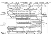
- FIG. 4 is a signaling diagram of an alternative process 400 to the first embodiment.
- Process 400 is similar to process 300 except the PDG 129 remains on the call path after the connectivity to the WLAN 140a is terminated.
- the PDG 129 will be in the middle of the call path after the handover.
- the handover is performed by switching the signaling path in the P-CSCF toward the GGSN 128 from the PDG 129.
- the traffic is directed from the PDG 129 to the GGSN 128.
- Steps 402-416 are the same as corresponding steps 302-316 and will not be repeated herein.
- the PDG 129 After receiving the relocation request from the AP 132a, the PDG 129 sends a tunnel establishment request to the GGSN 128 and the GGSN 128 responds with a tunnel establishment response. At such point a tunnel is established between the PDG 129 and the GGSN 128.
- the GGSN 128 establishes the SIP connectivity to the IMS 150 through the PDG 129 (steps 422, 424).
- the PDG 129 sends a relocation response to the AP 132a (step 426).
- the AP 132a then releases the resources after sending a handover complete message to the WTRU 102 (step 428).
- the GGSN 128 also sends the handover complete message for resource allocation to the Node-B 112 via the SGSN 122 (steps 430, 432).
- the Node-B 112 then sends the handover complete message to the WTRU 102 (step 434).
- the services from the IMS 150 are then provided through the UMTS network 110, (i.e., from the IMS 150 via the PDG 129, the GGSN 128, the SGSN 122 and the Node-B 112 to the WTRU 102 as indicated by arrows 436a-436c) (step 436).
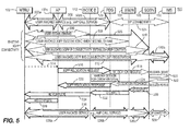
- FIG. 5 is a signaling diagram of a process 500 for interworking in accordance with a second embodiment of the present invention.
- the WTRU 102 may maintain multiple sessions simultaneously and the existing connectivity to the WLAN 130a is not torn down after the handover is complete. Two connections are maintained simultaneously and the application is transferred from one network to the other, (i.e., "simultaneous").
- the WTRU 102 invokes a service, such as VoIP call services (step 502).
- the WTRU 102 sends a request to the AP 132a (step 502a) and the AP 132a forwards the request to the PDG 129 (step 502b).
- the step 504 between the PDG 129 and the IMS 150 indicates the steps taken place to establish the connection between the PDG 129 and the IMS 150, such as SIP registration, allocation of P-CSCF and the allocation of S-CSCF.
- the WTRU 102 establishes an additional connection to the UMTS network 110 concurrently.
- the WTRU 102 establishes a connection to the GGSN 128 as indicated by arrow 505 by the following steps 506-510.
- the WTRU 102 establishes an RAB to a Node-B 112 (step 506) and invokes a 3GPP system attachment (step 508).
- the WTRU 102 then invokes 3GPP IP connectivity by establishing a PDP context (step 510).
- the WTRU 102 sets up a PDP context, the WTRU 102 selects an access point and an APN is determined. The APN is used in a DNS query. This process finally gives an IP address of the GGSN 128 which serves the access point.
- the WTRU 102 then invokes 3GPP IMS connectivity through SIP registration at step 512 at such point the connection between the GGSN 128 and the IMS 150 is also established as indicated by arrow 512a.
- the application is transferred from the WLAN 130a to the UMTS network 110 without breaking the existing connection to the WLAN 130a.
- the WTRU 102 sends a handover request to the AP 132a (step 514).
- the handover request identifies the tunnel end points, the user ID, radio resources, frequency channels, priority, or the like.
- the AP 132a then sends a 3GPP relocation request to the PDG 129 (step 516).
- the PDG 129 may be removed from the call path after the connection is switched to the UMTS or may remain on the call path.
- Figure 5 illustrates the first option and the second option will be explained with reference to Figure 6 hereinafter.
- the PDG 129 forwards the request to the GGSN 128, and the GGSN 128 forwards the request to the IMS 150 (steps 518, 520).
- the PDG 129 is removed from the call path after the connectivity to the WLAN 130a is switched.
- the tunnel between the PDG 129 and the GGSN 128 lasts only for a certain interval, and a new connection between the GGSN 128 and the IMS 150 is established and traffic is forwarded directly from the IMS 150 to the GGSN 128 where the WTRU 102 is connected.
- the IMS 150 sends a relocation response to the GGSN 128, which forwards the response to the PDG 129 (steps 522, 524).
- the PDG 129 sends a relocation response to the AP 132a (step 526).
- the AP 132a then releases the resources after sending a handover complete message to the WTRU 102 (step 528).
- the GGSN 128 also sends the handover complete message for resource allocation to the Node-B 112 via the SGSN 122 (steps 530, 532).
- the Node-B 112 then sends the handover complete message to the WTRU 102 (step 534).
- the services from the IMS 150 are then provided through the UMTS network 110, (i.e., from the IMS 150 via the GGSN 128, the SGSN 122 and the Node-B 112 to the WTRU 102 as indicated by arrows 536a-536c) (steps 536, 538).
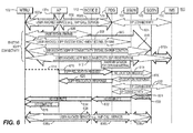
- FIG. 6 is a signaling diagram of a process 600 which is an alternative to the second embodiment of the present invention.
- Process 600 is similar to process 500 except the PDG 129 remains on the call path after the connectivity to the WLAN 130a is switched. The PDG 129 will be in the middle of the call path after the handover.
- Steps 602-616 are the same as corresponding steps 502-516 of process 500 and will not be repeated herein.
- the PDG 129 After receiving the relocation request from the AP 132a, the PDG 129 sends a tunnel establishment request to the GGSN 128 and the GGSN 128 responds with a tunnel establishment response (steps 618, 620). At such point a tunnel is established between the PDG 129 and the GGSN 128.
- the GGSN 128 establishes the SIP connectivity to the IMS 150 through the PDG 129 (steps 622, 624).
- the PDG 129 sends a relocation response to the AP 132a (step 626).
- the AP 132a then releases the resources at step 629 after sending a handover complete message to the WTRU 102 (step 628).
- the GGSN 128 also sends the handover complete message for resource allocation to the Node-B 112 via the SGSN 122 (steps 630, 632).
- the Node-B 112 then sends the handover complete message to the WTRU 102 (step 634).
- the services from the IMS 150 are then provided through the UMTS network, (i.e., from the IMS 150 via the PDG 129, the GGSN 128, the SGSN 122 and the Node-B 112 to the WTRU 102 as indicated by arrows 636a-636c) (step 636).
- FIG. 7 is a signaling diagram of a process 700 for interworking in accordance with a third embodiment of the present invention.
- the existing connectivity to the WLAN 130a is torn down before handover to the UMTS network 110, (i.e., "break before make”).
- the WTRU 102 invokes the indicated service (step 702).
- the WTRU 102 sends a request to the AP 132a (step 702a) and the AP 132a forwards the request to the PDG 129 (step 702b).
- the step 704 between the PDG 129 and the IMS 150 indicates the steps taken place to establish the connection between the PDG and the IMS, such as SIP registration, allocation of P-CSCF and the allocation of S-CSCF.
- a new connectivity to the UMTS network 110 is established after breaking the existing connectivity to the current WLAN hotspot 130a, (e.g., loss of signal).
- the WTRU may initiate the handover to the UMTS system or alternatively the WLAN may initiate the handover. Since the WLAN is connected to the PDG 129, the WLAN may initiate the handover to the target UMTS system.
- the AP 132a sends a message, (a relocation request), to the PDG 129 (step 708). The session is then maintained for a certain interval (step 710).
- the WTRU 102 then establishes a connection to the GGSN 128 as indicated by arrow 711 by the following steps 712-716.
- the WTRU 102 establishes an RAB to a Node-B 112 (step 712) and invokes a 3GPP system attachment (step 714).
- the WTRU 102 then invokes 3GPP IP connectivity by establishing a PDP context (step 716).
- the WTRU 102 sets up a PDP context, the WTRU 102 selects an access point and an APN is determined. The APN is used in a DNS query. This process finally gives an IP address of the GGSN 128 which serves the access point.
- the WTRU 102 then invokes 3GPP IMS connectivity through SIP registration at step 718, at such point the connection between the GGSN 128 and the IMS 150 is also established as indicated by arrow 718a.
- a handover bending session is then initiated (step 720).
- the WTRU 102 sends the information related to the existing session to the IMS 150, (i.e., SIP server).
- the information includes the session/service identification, originating and terminating IP addresses, a request to redirect the traffic to the UMTS system with the new contact information, (i.e., current IP address), or the like.
- the IMS 150 then updates the new routing of the call/session.
- the IMS 150 establishes a new P-CSCF and S-CSCF for the new session.
- the IMS 150 then sends a handover request notification to the PDG 129 with information regarding the session and indications that the call/session has been redirected and resources previously reserved should be released (step 722).
- the PDG 129 then sends a relocation response to the AP 132a along with the session information and WTRU identity (step 724).
- the AP 132a then releases resources allocated for the WTRU 102.
- the session is resumed between the WTRU 102 and the IMS 150 (steps 726a-726d) and user invoked services are provided from the IMS 150 via the GGSN 128, the SGSN 122 and the Node-B 112 to the WTRU 102 (step 728).
- the PDG 129 may indicate a handover to the IMS 150.
- the WTRU 102 may indicate the handover to the IMS 150 and provide the old connection information.
Description
- The present invention is related to wireless communication systems. More specifically, the present invention is a method and system for interworking between cellular networks and wireless local area networks (WLANs).
- Different types of wireless communication networks are presently deployed, such as WLANs and cellular networks. A multi-mode wireless transmit/receive unit (WTRU) supports wireless communication in more than one wireless communication network. As a user of the multi-mode WTRU roams between different networks, it is necessary to perform handover from one network to the other while receiving services continuously. For example, a wireless subscriber may roam between a WLAN and a third generation (3G) network while maintaining continuity in the wireless service provided to the user. Therefore, there is a need for coordination between the WTRU and the networks such that the service continuity is maintained as the user roams between different wireless networks.
- The present invention is related to a method and system for interworking between cellular networks and WLANs. At least one cellular network, at least one WLAN and an IP network are deployed. The WLAN includes an access point (AP). The cellular network includes a radio access network and a core network. The radio access network includes a Node-B and a radio network controller, and the core network includes a packet data gateway (PDG), a serving GPRS support node (SGSN) and a gateway GPRS support node (GGSN).
- A WTRU first establishes a connection to a WLAN and a tunnel between an AP and a PDG is established. The PDG further establishes a tunnel to an IP network. The WTRU then invokes a service which is delivered through the WLAN. As signal quality from the AP degrades below a predetermined threshold, a handover from the WLAN to the cellular network is performed. A new connection to the cellular network may be established either before or after breaking the current connection to the WLAN or the two connections may be maintained simultaneously.
- A more detailed understanding of the invention may be had from the following description of preferred embodiments, given by way of example and to be understood in conjunction with the accompanying drawings, wherein:
-
Figure 1 is a block diagram of a UMTS-WLAN architecture; -
Figure 2 is a signaling diagram of a process for access to 3G based services through a WLAN; -
Figure 3 is a signaling diagram of a process for interworking in accordance with a first embodiment of the present invention; -
Figure 4 is a signaling diagram of an alternative process for interworking in accordance with an alternative to the first embodiment of the present invention; -
Figure 5 is a signaling diagram of a process for interworking in accordance with a second embodiment of the present invention; -
Figure 6 is a signaling diagram of an alternative process for interworking in accordance with an alternative to the second embodiment of the present invention; and -
Figure 7 is a signaling diagram of a process for interworking in accordance with a third embodiment of the present invention. - The present invention will be described with reference to the drawing figures wherein like numerals represent like elements throughout.
- When referred to hereinafter, the terminology "WTRU" includes but is not limited to a user equipment, a mobile station, a fixed or mobile subscriber unit, a pager, or any other type of device capable of operating in a wireless environment. When referred to hereinafter, the terminology "Node-B" and "AP" includes but is not limited to a base station, a site controller or any other type of interfacing device in a wireless environment.
- The present invention provides methods for maintaining service continuity and seamless handover between a WLAN and a cellular network by defining steps for establishing the cellular network connectivity, steps for performing a handover, and steps for breaking the connectivity between the user and the WLAN. It should be noted that the cellular network can be any type of cellular network including, but not limited to, a universal mobile telecommunication system (UMTS), cdma2000 and a global system for mobile communication (GSM), and the WLAN can be any type of WLAN including, but not limited to, an IEEE 802.x network.
-
Figure 1 is a block diagram of a UMTS-WLAN interworking network 100.WLANs WLAN IP network 140, (e.g., Internet), or acellular core network 120 for 3G-based services through the WLAN hotspot. -
Base stations 112 are deployed in the UMTS coverage area for access to UMTS networks. Thebase station 112 is connected to a radio network controller (RNC) 114 which is connected to thecellular core network 120. - The
cellular core network 120 comprises a circuit switched core network (not shown) and a packet switched core network (shown inFigure 1 ). The packet switchedcore network 120 comprises an SGSN 122, an authentication, authorization and accounting (AAA)server 124, a home location register (HLR)/home subscriber server (HSS) 126, a GGSN 128, aPDG 129 and a WLAN access gateway (WAG) 121. - Referring to
Figures 1 and2 , aprocess 200 for access to 3G-based services through WLAN is explained hereinafter. A WTRU 102 is currently in a service area of the WLANhotspot 130a. The WTRU 102 acquires system information of theWLAN hotspot 130a through active or passive scanning (step 202). In active scanning, the WTRU 102 sends a probe request to the AP 132a and the AP 132a sends a probe response in response to the probe request (steps step 202c). - After acquiring the system information, WLAN association and authentication procedures are performed. The WTRU 102 sends an association request message to the selected AP 132a (step 204) and the AP 132a sends an association response message to the WTRU 102 (step 206). At such point, an association is established and WLAN authentication procedure is performed (step 208).
- The WTRU 102 then initiates subscription and service authentication procedures by registering with the UMTS network for receiving UMTS-based services through the
WLAN 130a (step 210). The WLAN 130a resolves the Network Access Id (NAI) provided by the WTRU 102. The AR 134 uses the NAI to route AAA messages to therelevant AAA server 124 in the UMTScore network 120. TheAR 134 triggers extensible authentication protocol (EAP)-authentication key agreement (AKA) authentication and relay messages to a UMTSAAA server 124. Once the WTRU 102 receives an authentication success message, the WTRU 102 uses dynamic host configuration protocol (DHCP) to receive an IP address and then initiates a tunnel establishment with thePDG 129 through theWAG 121. The WTRU 102 constructs a fully qualified domain name (FQDN) and performs a domain name service (DNS) query for thePDG 129 from a DNS 142 (step 212). The WTRU 102 selects a PDG from the received list in the DNS query response and establishes an end-to-end tunnel between the selectedPDG 129 and the WTRU 102 (step 214). -
Figure 3 is a signaling diagram of aprocess 300 for interworking in accordance with the first embodiment of the present invention. In accordance with the first embodiment, a new connection to the UMTS network is established before breaking the current connection to the WLAN hotspot, (i.e., "make before break"). When establishing the tunnel atstep 214 inFigure 2 , the WTRU indicates an application, such as voice over IP (VoIP) services, and the tunnel is set up for this certain application. The tunnel is established by the WTRU 102 sending a request to the AP 132a (step 302a) and the AP 132a forwarding the request to the PDG 129 (step 302b). After the tunnel between the WTRU 102 and thePDG 129 is established, the WTRU 102 invokes the indicated service (step 302). - There are two options that may follow the indication of the application. One is that a request is sent to the
PDG 129 to establish the connection to the IP Multimedia Subsystem (IMS) 150 and allocate the Proxy Call State Control Function (P-CSCF) or the Session Initiation Protocol (SIP) proxy for theWTRU 102. The other option is that a request is sent to thePDG 129 to establish the tunnel and wait for theWTRU 102 to request a connection to theIMS 150 and the allocation of the SIP proxy or the P-CSCF is performed after the request for connection. The first option is preferred since it will save additional delay in setting up the call. However, the second option may be the implementation in certain situations. Thestep 304 between thePDG 129 and theIMS 150 indicates the steps taking place to establish the connection between thePDG 129 and theIMS 150, such as SIP registration, allocation of P-CSCF and the allocation of Serving CSCF (S-CSCF). A CSCF is a specific type of SIP server, which is used to process SIP signaling packets in an IMS network. A P-CSCF is an SIP proxy that is the first point of contact for the WTRU. An S-CSCF is a central node of the signaling plane. - As the
WTRU 102 moves away from thecurrent WLAN hotspot 130a, as shown inFigure 1 , a handover from thecurrent WLAN hotspot 130a to theUMTS network 110 is initiated. In accordance with this embodiment, a new connectivity to theUMTS network 110 is established before breaking the existing connectivity to thecurrent WLAN hotspot 130a. - Referring again to
Figure 3 , theWTRU 102 establishes a connection to theGGSN 128 as indicated byarrow 305 by the following steps 306-310. TheWTRU 102 first establishes a radio access bearer (RAB) to a Node-B 112 (step 306) and invokes a 3GPP system attachment (step 308). TheWTRU 102 then invokes 3GPP IP connectivity by establishing a packet data protocol (PDP) context (step 310). When theWTRU 102 sets up a PDP context, theWTRU 102 selects an access point and an access point name (APN) is determined. The APN is used in a DNS query. This process finally gives an IP address of theGGSN 128 which serves the access point. TheWTRU 102 then invokes 3GPP IMS connectivity through SIP registration atstep 312 at such point the connection between theGGSN 128 and theIMS 150 is also established as indicated byarrow 312a. - Once the connectivity to the
UMTS network 110 is established, a process for breaking the connectivity to thecurrent WLAN hotspot 130a is initiated. TheWTRU 102 sends a handover request to theAP 132a (step 314). The handover request identifies the tunnel end points, the user ID, radio resources, frequency channels, priority, or the like. TheAP 132a then sends a 3GPP relocation request to the PDG 129 (step 316). There are two options with respect to the 3GPP relocation request. ThePDG 129 may be removed from the call path after the connectivity to theWLAN 130a is terminated or thePDG 129 may remain on the call path after the connectivity to theWLAN 130a is terminated.Figure 3 illustrates the first option and the second option will be explained with reference toFigure 4 hereinafter. - In the first embodiment shown in
Figure 3 , thePDG 129 is removed from the call path after the connectivity to theWLAN 130a is terminated. ThePDG 129 forwards the request to theGGSN 128, and theGGSN 128 forwards the request to the IMS 150 (steps 318, 320). The tunnel between thePDG 129 and theGGSN 128 lasts only for the duration the connectivity to theWLAN 130a exists, and then a new connection between theGGSN 128 and theIMS 150 is established and traffic is forwarded directly from theIMS 150 to theGGSN 128 where theWTRU 102 is now connected. - The
IMS 150 sends a relocation response to theGGSN 128, which forwards the response to the PDG 129 (steps 322, 324). ThePDG 129 sends a relocation response to theAP 132a (step 326). TheAP 132a then releases the resources after sending a handover complete message to the WTRU 102 (step 328). TheGGSN 128 also sends the handover complete message, (i.e., HO complete), for resource allocation to the Node-B 112 via the SGSN 122 (steps 330, 332). The Node-B 112 then sends the handover complete message to the WTRU 102 (step 334). The services from theIMS 150 are then provided through theUMTS network 110, (i.e., from theIMS 150 via theGGSN 128, theSGSN 122 and the Node-B 112 to theWTRU 102 as indicated byarrows 336a-336c) (steps 336, 338). -
Figure 4 is a signaling diagram of analternative process 400 to the first embodiment.Process 400 is similar to process 300 except thePDG 129 remains on the call path after the connectivity to the WLAN 140a is terminated. ThePDG 129 will be in the middle of the call path after the handover. The handover is performed by switching the signaling path in the P-CSCF toward theGGSN 128 from thePDG 129. The traffic is directed from thePDG 129 to theGGSN 128. - Steps 402-416 are the same as corresponding steps 302-316 and will not be repeated herein. After receiving the relocation request from the
AP 132a, thePDG 129 sends a tunnel establishment request to theGGSN 128 and theGGSN 128 responds with a tunnel establishment response. At such point a tunnel is established between thePDG 129 and theGGSN 128. TheGGSN 128 establishes the SIP connectivity to theIMS 150 through the PDG 129 (steps 422, 424). ThePDG 129 sends a relocation response to theAP 132a (step 426). TheAP 132a then releases the resources after sending a handover complete message to the WTRU 102 (step 428). TheGGSN 128 also sends the handover complete message for resource allocation to the Node-B 112 via the SGSN 122 (steps 430, 432). The Node-B 112 then sends the handover complete message to the WTRU 102 (step 434). The services from theIMS 150 are then provided through theUMTS network 110, (i.e., from theIMS 150 via thePDG 129, theGGSN 128, theSGSN 122 and the Node-B 112 to theWTRU 102 as indicated byarrows 436a-436c) (step 436). -
Figure 5 is a signaling diagram of aprocess 500 for interworking in accordance with a second embodiment of the present invention. In accordance with the second embodiment, theWTRU 102 may maintain multiple sessions simultaneously and the existing connectivity to theWLAN 130a is not torn down after the handover is complete. Two connections are maintained simultaneously and the application is transferred from one network to the other, (i.e., "simultaneous"). - After the tunnel between the
WTRU 102 and thePDG 129 is established, theWTRU 102 invokes a service, such as VoIP call services (step 502). TheWTRU 102 sends a request to theAP 132a (step 502a) and theAP 132a forwards the request to the PDG 129 (step 502b). Thestep 504 between thePDG 129 and theIMS 150 indicates the steps taken place to establish the connection between thePDG 129 and theIMS 150, such as SIP registration, allocation of P-CSCF and the allocation of S-CSCF. - The
WTRU 102 establishes an additional connection to theUMTS network 110 concurrently. TheWTRU 102 establishes a connection to theGGSN 128 as indicated byarrow 505 by the following steps 506-510. TheWTRU 102 establishes an RAB to a Node-B 112 (step 506) and invokes a 3GPP system attachment (step 508). TheWTRU 102 then invokes 3GPP IP connectivity by establishing a PDP context (step 510). When theWTRU 102 sets up a PDP context, theWTRU 102 selects an access point and an APN is determined. The APN is used in a DNS query. This process finally gives an IP address of theGGSN 128 which serves the access point. TheWTRU 102 then invokes 3GPP IMS connectivity through SIP registration atstep 512 at such point the connection between theGGSN 128 and theIMS 150 is also established as indicated byarrow 512a. - As the
WTRU 102 moves away from thecurrent WLAN hotspot 130a, as shown inFigure 1 , the application is transferred from theWLAN 130a to theUMTS network 110 without breaking the existing connection to theWLAN 130a. TheWTRU 102 sends a handover request to theAP 132a (step 514). The handover request identifies the tunnel end points, the user ID, radio resources, frequency channels, priority, or the like. TheAP 132a then sends a 3GPP relocation request to the PDG 129 (step 516). As stated hereinbefore with respect to the first embodiment and its alternative, thePDG 129 may be removed from the call path after the connection is switched to the UMTS or may remain on the call path.Figure 5 illustrates the first option and the second option will be explained with reference toFigure 6 hereinafter. - The
PDG 129 forwards the request to theGGSN 128, and theGGSN 128 forwards the request to the IMS 150 (steps 518, 520). ThePDG 129 is removed from the call path after the connectivity to theWLAN 130a is switched. The tunnel between thePDG 129 and theGGSN 128 lasts only for a certain interval, and a new connection between theGGSN 128 and theIMS 150 is established and traffic is forwarded directly from theIMS 150 to theGGSN 128 where theWTRU 102 is connected. - The
IMS 150 sends a relocation response to theGGSN 128, which forwards the response to the PDG 129 (steps 522, 524). ThePDG 129 sends a relocation response to theAP 132a (step 526). TheAP 132a then releases the resources after sending a handover complete message to the WTRU 102 (step 528). TheGGSN 128 also sends the handover complete message for resource allocation to the Node-B 112 via the SGSN 122 (steps 530, 532). The Node-B 112 then sends the handover complete message to the WTRU 102 (step 534). The services from theIMS 150 are then provided through theUMTS network 110, (i.e., from theIMS 150 via theGGSN 128, theSGSN 122 and the Node-B 112 to theWTRU 102 as indicated byarrows 536a-536c) (steps 536, 538). -
Figure 6 is a signaling diagram of aprocess 600 which is an alternative to the second embodiment of the present invention.Process 600 is similar to process 500 except thePDG 129 remains on the call path after the connectivity to theWLAN 130a is switched. ThePDG 129 will be in the middle of the call path after the handover. - Steps 602-616 are the same as corresponding steps 502-516 of
process 500 and will not be repeated herein. After receiving the relocation request from theAP 132a, thePDG 129 sends a tunnel establishment request to theGGSN 128 and theGGSN 128 responds with a tunnel establishment response (steps 618, 620). At such point a tunnel is established between thePDG 129 and theGGSN 128. TheGGSN 128 establishes the SIP connectivity to theIMS 150 through the PDG 129 (steps 622, 624). ThePDG 129 sends a relocation response to theAP 132a (step 626). TheAP 132a then releases the resources at step 629 after sending a handover complete message to the WTRU 102 (step 628). TheGGSN 128 also sends the handover complete message for resource allocation to the Node-B 112 via the SGSN 122 (steps 630, 632). The Node-B 112 then sends the handover complete message to the WTRU 102 (step 634). The services from theIMS 150 are then provided through the UMTS network, (i.e., from theIMS 150 via thePDG 129, theGGSN 128, theSGSN 122 and the Node-B 112 to theWTRU 102 as indicated byarrows 636a-636c) (step 636). -
Figure 7 is a signaling diagram of aprocess 700 for interworking in accordance with a third embodiment of the present invention. In accordance with the third embodiment, the existing connectivity to theWLAN 130a is torn down before handover to theUMTS network 110, (i.e., "break before make"). After the tunnel between theWTRU 102 and thePDG 129 is established, theWTRU 102 invokes the indicated service (step 702). To invoke the indicated service, theWTRU 102 sends a request to theAP 132a (step 702a) and theAP 132a forwards the request to the PDG 129 (step 702b). Thestep 704 between thePDG 129 and theIMS 150 indicates the steps taken place to establish the connection between the PDG and the IMS, such as SIP registration, allocation of P-CSCF and the allocation of S-CSCF. - As the
WTRU 102 moves away from thecurrent WLAN hotspot 130a, as shown inFigure 1 , handover from thecurrent WLAN hotspot 130a to theUMTS network 110 is performed. In accordance with this embodiment, a new connectivity to theUMTS network 110 is established after breaking the existing connectivity to thecurrent WLAN hotspot 130a, (e.g., loss of signal). - When the signal from the
AP 132a is lost (step 706), the WTRU may initiate the handover to the UMTS system or alternatively the WLAN may initiate the handover. Since the WLAN is connected to thePDG 129, the WLAN may initiate the handover to the target UMTS system. When the signal loss is detected, theAP 132a sends a message, (a relocation request), to the PDG 129 (step 708). The session is then maintained for a certain interval (step 710). - The
WTRU 102 then establishes a connection to theGGSN 128 as indicated byarrow 711 by the following steps 712-716. TheWTRU 102 establishes an RAB to a Node-B 112 (step 712) and invokes a 3GPP system attachment (step 714). TheWTRU 102 then invokes 3GPP IP connectivity by establishing a PDP context (step 716). When theWTRU 102 sets up a PDP context, theWTRU 102 selects an access point and an APN is determined. The APN is used in a DNS query. This process finally gives an IP address of theGGSN 128 which serves the access point. TheWTRU 102 then invokes 3GPP IMS connectivity through SIP registration atstep 718, at such point the connection between theGGSN 128 and theIMS 150 is also established as indicated byarrow 718a. - A handover bending session is then initiated (step 720). The
WTRU 102 sends the information related to the existing session to theIMS 150, (i.e., SIP server). The information includes the session/service identification, originating and terminating IP addresses, a request to redirect the traffic to the UMTS system with the new contact information, (i.e., current IP address), or the like. TheIMS 150 then updates the new routing of the call/session. TheIMS 150 establishes a new P-CSCF and S-CSCF for the new session. - The
IMS 150 then sends a handover request notification to thePDG 129 with information regarding the session and indications that the call/session has been redirected and resources previously reserved should be released (step 722). ThePDG 129 then sends a relocation response to theAP 132a along with the session information and WTRU identity (step 724). TheAP 132a then releases resources allocated for theWTRU 102. The session is resumed between theWTRU 102 and the IMS 150 (steps 726a-726d) and user invoked services are provided from theIMS 150 via theGGSN 128, theSGSN 122 and the Node-B 112 to the WTRU 102 (step 728). - The
PDG 129 may indicate a handover to theIMS 150. Alternatively, theWTRU 102 may indicate the handover to theIMS 150 and provide the old connection information. -
- 1. A method for interworking between a cellular network and a WLAN for a user service provided by an IMS, whereby the user service is continuously provided through the cellular network after the handover. A WTRU initially establishes a connection to a WLAN and establishes a tunnel between the WLAN and a PDG of the cellular network and, in turn, a tunnel between the PDG and an IP network to receive a user service through the WLAN. The WTRU establishes a connection to the cellular network and performs a handover from the WLAN to the cellular network by sending a handover signaling through the WLAN.
- 2. The method of example 1, wherein the PDG sends a relocation request to a GGSN of the cellular network when the PDG receives the handover request, whereby the PDG is removed from a call path after the handover is performed, and the call path between the IMS and the WTRU is established through the GGSN.
- 3. The method of example 1, wherein the PDG sends a tunnel establishment request to a GGSN when the PDG receives the handover request, whereby the PDG remains on a call path after the handover is performed, and the call path between the IMS and the WTRU is established via the GGSN and the PDG.
- 4. The method of any one of examples 1-3 wherein a tunnel between the PDG and the IMS is established after indication of the service.
- 5. The method of any one of examples 1-3, wherein the tunnel between the PDG and the IMS is established after a request from the WTRU.
- 6. The method of any one of examples 1-5, wherein the handover request identifies tunnel end points.
- 7. The method of any one of examples 1-6, wherein the handover request identifies user identity (ID).
- 8. The method of any one of examples 1-7, wherein the handover request identifies radio resources.
- 9. The method of any one of examples 1-8, wherein the handover request identifies frequency channels.
- 10. The method of any one of examples 1-9, wherein the handover request identifies priority.
- 11. The method of any one of examples 1-10, wherein the connection to the WLAN is terminated after the connection to the cellular network is established.
- 12. The method of any one of examples 1-11, wherein the connection to the WLAN and the connection to the cellular network are maintained simultaneously.
- 13. A method for interworking between a cellular network and a WLAN for a user service provided by the IMS, whereby the user service is continuously provided through the cellular network. A WTRU establishes a connection to a WLAN and a tunnel between the WLAN and a PDG and, in turn, a tunnel between the PDG and an IP network to receive a user service through the WLAN. The WTRU establishes a connection to the cellular network when the connection to the WTRU is broken and initiates a handover bending session to recover the session and performs a handover from the WLAN to the cellular network.
- 14. The method of example 13, wherein the handover to the cellular network is initiated by the WLAN.
- 15. The method of example 13, wherein the handover to the cellular network is initiated by a user.
- 16. A system for interworking between the cellular network and the WLAN for a user service provided by the IMS, whereby the WTRU continuously receives the user service through the cellular network after handover by establishing a connection to the cellular network. The cellular network comprises a radio access network and a core network which includes a PDG, a SGSN and a GGSN. The WLAN is configured to establish a tunnel between the WLAN and the PDG and the PDG is configured to establish a tunnel between the PDG and the IMS. The WTRU is configured to communicate with both the WLAN and the cellular network and to perform a handover from the WLAN to the cellular network by sending a handover signaling through the WLAN.
- 17. The system of example 16, wherein the PDG sends a relocation request to the GGSN when the PDG receives the handover request, whereby the PDG is removed from a call path after the handover is performed, and the call path between the IMS and the WTRU is established through the GGSN.
- 18. The system of example 16, wherein the PDG sends a tunnel establishment request to the GGSN when the PDG receives the handover request, whereby the PDG remains on a call path after the handover is performed, and the call path between the IMS and the WTRU is established via the GGSN and the PDG.
- 19. The system of any one of examples 16-18, wherein a tunnel between the PDG and an IMS is established after indication of the service.
- 20. The system of any one of examples 16-18, wherein a tunnel between the PDG and an IMS is established after a request from the WTRU.
- 21. The system of any one of examples 16-20, wherein the handover request identifies tunnel end points.
- 22. The system of any one of examples 16-21, wherein the handover request identifies user identity (ID).
- 23. The system of any one of examples 16-22, wherein the handover request identifies radio resources.
- 24. The system of any one of examples 16-23, wherein the handover request identifies frequency channels.
- 25. The system of any one of examples 16-24, wherein the handover request identifies priority.
- 26. The system of any one of examples 16-25, wherein the connection to the WLAN is terminated after the connection to the cellular network is established.
- 27. The system of any one of examples 16-26, wherein the connection to the WLAN and the connection to the cellular network are maintained simultaneously.
- 28. A system for interworking between a cellular network and a WLAN for a user service provided by the IMS, whereby the WTRU continuously receives the user service through the cellular network after handover by establishing a connection to the cellular network after a connection to the WLAN is broken. The cellular network comprises a radio access network and a core network which includes a PDG, a SGSN and a GGSN. The WLAN is configured to establish a tunnel between the WLAN and the PDG of the cellular network and the PDG is configured to establish a tunnel between the PDG and the IMS. The WTRU is configured to communicate with both the WLAN and the cellular network and to perform a handover from the WLAN to the cellular network by establishing a connection to the cellular network when the connection to the WTRU is broken by initiating a handover bending session.
- 29. The system of example 28, wherein the handover to the cellular network is initiated by the WLAN.
- 30. The system of example 28, wherein the handover to the cellular network is initiated by a user.
- 31. In a wireless communication system including at least one cellular network, at least one wireless local area network (WLAN) and an IP multimedia subsystem (IMS), a method for interworking between the cellular network and the WLAN for a user service provided by the IMS, the method comprising: a WTRU establishing a connection to a WLAN; establishing a tunnel between the WLAN and a packet data gateway (PDG) of the cellular network, the PDG further establishing a tunnel between the PDG and an IP network; the WTRU invoking a user service and receiving the user service through the WLAN; the WTRU establishing a connection to the cellular network; and performing a handover from the WLAN to the cellular network by sending a handover signaling through the WLAN, whereby the user service is continuously provided through the cellular network after the handover.
- 32. The method of example 31, wherein the PDG sends a relocation request to a gateway GPRS support node (GGSN) when the PDG receives the handover request, whereby the PDG is removed from a call path after the handover is performed, and the call path between the IMS and the WTRU is established through the GGSN.
- 33. The method of example 31, wherein the PDG sends a tunnel establishment request to a gateway GPRS support node (GGSN) when the PDG receives the handover request, whereby the PDG remains on a call path after the handover is performed, and the call path between the IMS and the WTRU is established via the GGSN and the PDG.
- 34. The method of example 31, wherein the tunnel between the PDG and the IMS is established after indication of the service.
- 35. The method of example 31, wherein the tunnel between the PDG and the IMS is established after a request from the WTRU.
- 36. The method of example 31, wherein the handover request identifies tunnel end points.
- 37. The method of example 31, wherein the handover request identifies user identity (ID).
- 38. The method of example 31, wherein the handover request identifies radio resources.
- 39. The method of example 31, wherein the handover request identifies frequency channels.
- 40. The method of example 31, wherein the handover request identifies priority.
- 41. The method of example 31, wherein the connection to the WLAN is terminated after the connection to the cellular network is established.
- 42. The method of example 31, wherein the connection to the WLAN and the connection to the cellular network are maintained simultaneously.
- 43. In a wireless communication system including at least one cellular network, at least one wireless local area network (WLAN) and an IP multimedia subsystem (IMS), a method for interworking between the cellular network and the WLAN for a user service provided by the IMS, the method comprising: a WTRU establishing a connection to a WLAN; establishing a tunnel between the WLAN and a packet data gateway (PDG) of the cellular network, the PDG further establishing a tunnel between the PDG and an IP network; the WTRU initiating a session for a user service and receiving the user service through the WLAN; the WTRU establishing a connection to the cellular network when the connection to the WTRU is broken; initiating a handover bending session to recover the session; and performing a handover from the WLAN to the cellular network, whereby the user service is continuously provided through the cellular network.
- 44. The method of example 43, wherein the handover to the cellular network is initiated by the WLAN.
- 45. The method of example 43, wherein the handover to the cellular network is initiated by a user.
- 46. In a wireless communication system including at least one cellular network, at least one wireless local area network (WLAN) and an IP multimedia subsystem (IMS), a system for interworking between the cellular network and the WLAN for a user service provided by the IMS, the system comprising: a cellular network comprising a radio access network and a core network, the core network comprising a packet data gateway (PDG), a serving GPRS support node (SGSN) and a gateway GPRS support node (GGSN); a WLAN configured to establish a tunnel between the WLAN and the PDG of the cellular network upon initiation of the user service by a user, the PDG further establishing a tunnel between the PDG and the IMS; a dual mode WTRU configured to communicate with both the WLAN and the cellular network, the WTRU comprising a handover function to perform a handover from the WLAN to the cellular network by sending a handover signaling through the WLAN whereby the WTRU continuously receives the user service through the cellular network after handover.
- 47. The system of example 46, wherein the PDG sends a relocation request to the GGSN when the PDG receives the handover request, whereby the PDG is removed from a call path after the handover is performed, and the call path between the IMS and the WTRU is established through the GGSN.
- 48. The system of example 46, wherein the PDG sends a tunnel establishment request to the GGSN when the PDG receives the handover request, whereby the PDG remains on a call path after the handover is performed, and the call path between the IMS and the WTRU is established via the GGSN and the PDG.
- 49. The system of example 46, wherein the tunnel between the PDG and the IMS is established after indication of the service.
- 50. The system of example 46, wherein the tunnel between the PDG and the IMS is established after a request from the WTRU.
- 51. The system of example 46, wherein the handover request identifies tunnel end points.
- 52. The system of example 46, wherein the handover request identifies user identity (ID).
- 53. The system of example 46, wherein the handover request identifies radio resources.
- 54. The system of example 46, wherein the handover request identifies frequency channels.
- 55. The system of example 46, wherein the handover request identifies priority.
- 56. The system of example 46, wherein the connection to the WLAN is terminated after the connection to the cellular network is established.
- 57. The system of example 46, wherein the connection to the WLAN and the connection to the cellular network are maintained simultaneously.
- 58. In a wireless communication system including at least one cellular network, at least one wireless local area network (WLAN) and an IP multimedia subsystem (IMS), a system for interworking between the cellular network and the WLAN for a user service provided by the IMS, the system comprising: a cellular network comprising a radio access network and a core network, the core network comprising a packet data gateway (PDG), a serving GPRS support node (SGSN) and a gateway GPRS support node (GGSN); a WLAN configured to establish a tunnel between the WLAN and the PDG of the cellular network upon initiation of the user service by a user, the PDG further establishing a tunnel between the PDG and the IMS; a dual mode WTRU configured to communicate with both the WLAN and the cellular network, the WTRU comprising a handover function to perform a handover from the WLAN to the cellular network by establishing a connection to the cellular network when the connection to the WTRU is broken and initiating a handover bending session to recover the session, whereby the WTRU continuously receives the user service through the cellular network after handover.
- 59. The system of example 58, wherein the handover to the cellular network is initiated by the WLAN.
- 60. The system of example 58, wherein the handover to the cellular network is initiated by a user.
- Although the features and elements of the present invention are described in the preferred examples in particular combinations, each feature or element can be used alone without the other features and elements of the preferred examples or in various combinations with or without other features and elements of the present invention.
Claims (13)
- A wireless transmit/receive unit, WTRU, (102) comprising:at least one transceiver for receiving a user service from an Internet Protocol, IP, multimedia subsystem, IMS, (150) via a wireless local area network, WLAN, (130),and a packet data gateway, PDG,
wherein the transceiver is configured to register with the IMS via the WLAN using Session Initiation Protocol, SIP; anda handover controlling entity for initiating a handover of the user service from the WLAN to a cellular network (110),characterized in that
the at least one transceiver is configured to perform the handover while continuously receiving the user service from the IMS during the handover and maintaining a connection to the WLAN while simultaneously maintaining a connection to the cellular network. - The WTRU of claim 1, wherein the at least one transceiver is further configured
to obtain the address of a packet data gateway, PDG, using Domain Name Service, DNS, via the WLAN; and
to establish a tunnel between the WTRU and the PDG. - The WTRU of claim 2, wherein the at least one transceiver is further configured to receive the user service from the IMS via the WLAN and the tunnel between the WTRU and the PDG.
- A method used in a wireless transmit/receive unit, WTRU, (102), the method comprising:establishing a connection with a Wireless Local Area Network, WLAN (130);invoking an IP session for a user service from an Internet Protocol, IP, multimedia subsystem, IMS, (150), wherein the WTRU registers with the IMS via the WLAN using Session Initiation Protocol, SIP;receiving the user service via a packet data gateway, PDG, and the WLAN;initiating a handover from the WLAN to a cellular network (110);characterized byperforming the handover while continuously receiving the user service from the IMS during the handover and maintaining a connection to the WLAN and a connection to the cellular network simultaneously.
- The method of claim 4, wherein the receiving the user service is also performed via the IMS.
- The method of claim 4 or 5, wherein the user service is a voice call service.
- The method of any of claims 4 to 6, further comprising:obtaining the address of the PDG using Domain Name Service, DNS, via the WLAN.
- The method of claim 7, further comprising:establishing a tunnel between the WTRU and the PDG.
- The wireless transmit/receive unit, WTRU, of claim 3, wherein said at least one transceiver is configured for:establishing a connection to the WLAN;invoking an IP session for the user service from the IMS; andestablishing a connection to the cellular network.
- The WTRU of claim 9, wherein the at least one transceiver is further configured to disconnect from the PDG in response to completion of the handover.
- The WTRU of claim 9 or 10, wherein the user service is a voice call service.
- The WTRU of any of claims 9 to 11, wherein the at least one transceiver is further configured
to send a DNS query for the address of the PDG; and
to receive a response to the DNS query, the response including the address of the PDG. - The WTRU of any of claims 9 to 12, wherein the at least one transceiver is further configured to terminate the connection to the WLAN in response to establishing the connection to the cellular network.
Applications Claiming Priority (3)
| Application Number | Priority Date | Filing Date | Title |
|---|---|---|---|
| US63467904P | 2004-12-09 | 2004-12-09 | |
| US11/285,684 US8130718B2 (en) | 2004-12-09 | 2005-11-22 | Method and system for interworking of cellular networks and wireless local area networks |
| EP05853721.8A EP1825696B1 (en) | 2004-12-09 | 2005-12-09 | Method and system for interworking of cellular networks and wireless local area networks |
Related Parent Applications (1)
| Application Number | Title | Priority Date | Filing Date |
|---|---|---|---|
| EP05853721.8A Division EP1825696B1 (en) | 2004-12-09 | 2005-12-09 | Method and system for interworking of cellular networks and wireless local area networks |
Publications (2)
| Publication Number | Publication Date |
|---|---|
| EP2688340A1 EP2688340A1 (en) | 2014-01-22 |
| EP2688340B1 true EP2688340B1 (en) | 2015-04-22 |
Family
ID=36578659
Family Applications (5)
| Application Number | Title | Priority Date | Filing Date |
|---|---|---|---|
| EP15162574.6A Not-in-force EP2941053B1 (en) | 2004-12-09 | 2005-12-09 | Method and system for interworking of cellular networks and wireless local area networks |
| EP20130181039 Not-in-force EP2683197B1 (en) | 2004-12-09 | 2005-12-09 | Method and system for interworking of cellular networks and wireless local area networks |
| EP05853721.8A Not-in-force EP1825696B1 (en) | 2004-12-09 | 2005-12-09 | Method and system for interworking of cellular networks and wireless local area networks |
| EP20130180851 Not-in-force EP2688340B1 (en) | 2004-12-09 | 2005-12-09 | Method and system for interworking of cellular networks and wireless local area networks |
| EP17177144.7A Withdrawn EP3273721A1 (en) | 2004-12-09 | 2005-12-09 | Method and system for interworking of cellular networks and wireless local area networks |
Family Applications Before (3)
| Application Number | Title | Priority Date | Filing Date |
|---|---|---|---|
| EP15162574.6A Not-in-force EP2941053B1 (en) | 2004-12-09 | 2005-12-09 | Method and system for interworking of cellular networks and wireless local area networks |
| EP20130181039 Not-in-force EP2683197B1 (en) | 2004-12-09 | 2005-12-09 | Method and system for interworking of cellular networks and wireless local area networks |
| EP05853721.8A Not-in-force EP1825696B1 (en) | 2004-12-09 | 2005-12-09 | Method and system for interworking of cellular networks and wireless local area networks |
Family Applications After (1)
| Application Number | Title | Priority Date | Filing Date |
|---|---|---|---|
| EP17177144.7A Withdrawn EP3273721A1 (en) | 2004-12-09 | 2005-12-09 | Method and system for interworking of cellular networks and wireless local area networks |
Country Status (19)
| Country | Link |
|---|---|
| US (3) | US8130718B2 (en) |
| EP (5) | EP2941053B1 (en) |
| JP (6) | JP4934593B2 (en) |
| KR (1) | KR101092742B1 (en) |
| CN (1) | CN102209357B (en) |
| AR (2) | AR051525A1 (en) |
| AU (2) | AU2005314406B2 (en) |
| BR (1) | BRPI0517160A (en) |
| CA (1) | CA2589768A1 (en) |
| DE (1) | DE202005019276U1 (en) |
| ES (4) | ES2433932T3 (en) |
| HK (1) | HK1111039A1 (en) |
| IL (1) | IL183452A (en) |
| MX (1) | MX2007006869A (en) |
| MY (1) | MY143929A (en) |
| NO (1) | NO340066B1 (en) |
| SG (1) | SG158116A1 (en) |
| TW (6) | TWI672935B (en) |
| WO (1) | WO2006063330A2 (en) |
Families Citing this family (86)
| Publication number | Priority date | Publication date | Assignee | Title |
|---|---|---|---|---|
| US8478281B2 (en) * | 2007-12-13 | 2013-07-02 | Agere Systems Llc | Cell phone extension using wireless piconet |
| US7680133B2 (en) * | 2004-07-28 | 2010-03-16 | Broadcom Corporation | Simulcasting or multicasting of multimedia call sessions in a LAN/WLAN/PAN via a broadband access gateway |
| US8130718B2 (en) * | 2004-12-09 | 2012-03-06 | Interdigital Technology Corporation | Method and system for interworking of cellular networks and wireless local area networks |
| WO2006063536A1 (en) * | 2004-12-17 | 2006-06-22 | Huawei Technologies Co., Ltd. | A method and system of holding session continuity |
| US20090185522A1 (en) | 2005-01-07 | 2009-07-23 | Nortel Networks Limited | Systems and methods for distributing content in wireless networks |
| US8804653B2 (en) | 2005-01-13 | 2014-08-12 | Telefonaktiebolaget Lm Ericsson (Publ) | System and method for call handoff between circuit switched and packet data wireless networks |
| US20060256752A1 (en) * | 2005-05-10 | 2006-11-16 | Telefonaktiebolaget Lm Ericsson (Publ) | System and method for call handoff from packet data wireless network to circuit switched wireless network |
| FI20050500A0 (en) * | 2005-05-11 | 2005-05-11 | Nokia Corp | A method for implementing inter-system handovers in a mobile communication system |
| DK1938545T3 (en) * | 2005-09-27 | 2009-11-30 | Ericsson Telefon Ab L M | Network architecture and method of accessing user stations |
| US20070121642A1 (en) * | 2005-11-02 | 2007-05-31 | Battin Robert D | Method and system for supporting an emergency call |
| WO2007096884A2 (en) | 2006-02-22 | 2007-08-30 | Elad Barkan | Wireless internet system and method |
| US8090401B2 (en) * | 2006-05-19 | 2012-01-03 | Agere Systems Inc. | Virtual gateway node for dual-mode wireless phones |
| FR2904914B1 (en) * | 2006-08-09 | 2008-09-26 | Alcatel Sa | INTERWORKING MANAGEMENT METHOD FOR TRANSFERRING SERVICE SESSIONS FROM A WIRELESS LOCAL NETWORK TO A MOBILE NETWORK, AND CORRESPONDING SGSN NODES |
| CN101128043B (en) | 2006-08-15 | 2011-02-02 | 华为技术有限公司 | Data processing method for switching between systems or change |
| US8116289B2 (en) * | 2006-08-30 | 2012-02-14 | Cisco Technology, Inc. | Internetworking nodes based on connections, membership, and location |
| US20080123640A1 (en) * | 2006-09-20 | 2008-05-29 | Ravideep Bhatia | Method for discovering outbound sip proxy server |
| US9191226B2 (en) * | 2006-09-28 | 2015-11-17 | Qualcomm Incorporated | Methods and apparatus for determining communication link quality |
| US7943094B2 (en) | 2006-12-07 | 2011-05-17 | Grupo Petrotemex, S.A. De C.V. | Polyester production system employing horizontally elongated esterification vessel |
| KR100861929B1 (en) * | 2007-01-23 | 2008-10-09 | 삼성전자주식회사 | Apparatus and method for providing pdg information |
| US8331315B2 (en) | 2007-02-16 | 2012-12-11 | Interdigital Technology Corporation | Media independent handover for smart phone architecture |
| US7894400B2 (en) * | 2007-02-16 | 2011-02-22 | Interdigital Technology Corporation | Handover between an IEEE 802.16 WiBro network and a UMTS network using media independent handover function |
| JP4548851B2 (en) * | 2007-03-09 | 2010-09-22 | 株式会社エヌ・ティ・ティ・ドコモ | Mobile communication method, radio base station, and upper node |
| US8576795B2 (en) * | 2007-03-16 | 2013-11-05 | Qualcomm Incorporated | Method and apparatus for handoff between source and target access systems |
| US8289920B2 (en) * | 2007-03-16 | 2012-10-16 | Qualcomm Incorporated | Method and apparatus for handoff between access systems |
| KR100879541B1 (en) | 2007-04-09 | 2009-01-22 | 삼성전자주식회사 | Apparatus of wireless communication in a dual mode portable terminal and Method thereof |
| US20080255280A1 (en) * | 2007-04-11 | 2008-10-16 | Susan Sims | Oxygen-scavenging polymer blends suitable for use in packaging |
| CN101431797B (en) | 2007-05-11 | 2012-02-01 | 华为技术有限公司 | Registration handling method, system and apparatus |
| US9049629B2 (en) * | 2007-06-18 | 2015-06-02 | Qualcomm Incorporated | Method and apparatus for fast inter-system handover |
| KR101394347B1 (en) * | 2007-06-20 | 2014-05-30 | 삼성전자주식회사 | Method and system for transporting packet between heterogeneous networks |
| CN101330753B (en) | 2007-06-22 | 2014-07-09 | 华为技术有限公司 | Method for establishing and erasuring resource as well as network appliance |
| US7844728B2 (en) * | 2007-07-31 | 2010-11-30 | Alcatel-Lucent Usa Inc. | Packet filtering/classification and/or policy control support from both visited and home networks |
| US7769828B2 (en) * | 2007-10-05 | 2010-08-03 | International Business Machines Corporation | System for provisioning time sharing option (TSO) and interactive productivity system facility (ISPF) services in a network environment |
| CN101150594B (en) * | 2007-10-18 | 2013-06-19 | 中国联合网络通信集团有限公司 | Integrated access method and system for mobile cellular network and WLAN |
| US8027309B2 (en) * | 2007-11-19 | 2011-09-27 | Cellco Partnership | Low latency handover between wireless communication networks using different radio access technologies |
| US8755793B2 (en) | 2008-01-04 | 2014-06-17 | Qualcomm Incorporated | Apparatus and methods to facilitate seamless handoffs between wireless communication networks |
| FI20080032A0 (en) | 2008-01-16 | 2008-01-16 | Joikusoft Oy Ltd | Smartphone as a WLAN access point |
| FI20080345A0 (en) | 2008-05-09 | 2008-05-09 | Joikusoft Oy Ltd | Symbian S60 phone as 3G bandwidth combiner |
| CN101583174B (en) * | 2008-05-12 | 2011-09-21 | 华为技术有限公司 | Communication method, cell base station and communication system |
| US8984105B2 (en) | 2008-05-27 | 2015-03-17 | Qualcomm Incorporated | FMC architecture for CDMA network |
| US8638749B2 (en) * | 2008-06-06 | 2014-01-28 | Qualcomm Incorporated | Method and apparatus for inter-network handoff |
| US20100097981A1 (en) * | 2008-10-16 | 2010-04-22 | Nishi Kant | Methods and systems for providing multiple media streams in a hybrid wireless network |
| US9083713B2 (en) | 2008-12-08 | 2015-07-14 | Qualcomm Incorporated | Apparatus and method for providing mobility to IMS sessions in mobile IP networks |
| EP2420077A1 (en) * | 2009-04-17 | 2012-02-22 | Panasonic Corporation | Apparatus for management of local ip access in a segmented mobile communication system |
| US20100329206A1 (en) * | 2009-06-30 | 2010-12-30 | Thome Timothy A | Dual idle-traffic state of wireless communication device |
| CN102106118B (en) * | 2009-09-28 | 2015-04-15 | 华为技术有限公司 | Scalable wlan gateway |
| WO2011041058A2 (en) * | 2009-10-01 | 2011-04-07 | Rambus Inc. | Methods and systems for enhancing wireless coverage |
| KR101587003B1 (en) * | 2010-09-07 | 2016-01-20 | 삼성전자주식회사 | Apparatus and method for determining validity of wifi connection in wireless communication system |
| US8675605B2 (en) | 2011-06-02 | 2014-03-18 | Broadcom Corporation | Frequency hopping in license-exempt/shared bands |
| GB2486926B (en) * | 2011-06-02 | 2013-10-23 | Renesas Mobile Corp | Frequency hopping in license-exempt/shared bands |
| WO2013052805A1 (en) | 2011-10-07 | 2013-04-11 | Interdigital Patent Holdings Inc. | Method and apparatus for integrating different radio access technologies using carrier aggregation |
| KR101843052B1 (en) * | 2011-10-25 | 2018-03-29 | 삼성전자주식회사 | Apparatus and method for providing voice call continuity using different networks in wirelss communication system |
| US20130107859A1 (en) * | 2011-10-27 | 2013-05-02 | Qualcomm Incorporated | AVOIDING VOICE OVER INTERNET PROTOCOL (VoIP) PACKET LOSS DUE TO INTER-RADIO ACCESS TECHNOLOGY (RAT) HANDOVER |
| KR101287192B1 (en) * | 2011-11-01 | 2013-07-17 | 에스케이텔레콤 주식회사 | System and method for data call access control |
| WO2014012227A1 (en) | 2012-07-18 | 2014-01-23 | 华为技术有限公司 | Data connection management method, device and system |
| EP2918135A1 (en) * | 2012-10-26 | 2015-09-16 | Interdigital Patent Holdings, Inc. | Systems and/or methods for improving packet-switched services during circuit switched fallback (csfb) |
| US20140126532A1 (en) * | 2012-11-05 | 2014-05-08 | Stoke, Inc. | Seamless mobility from 3g network to wifi network |
| US20140199963A1 (en) * | 2013-01-16 | 2014-07-17 | Behzad Mohebbi | Methods and apparatus for a network-agnostic wireless router |
| CN103974355B (en) * | 2013-01-24 | 2019-03-05 | 电信科学技术研究院 | A kind of method and device of network switching |
| WO2014121490A1 (en) * | 2013-02-07 | 2014-08-14 | Broadcom Corporation | Handover procedure between local area cells which are under the same coverage of a macro cell |
| US9992021B1 (en) | 2013-03-14 | 2018-06-05 | GoTenna, Inc. | System and method for private and point-to-point communication between computing devices |
| US20140269611A1 (en) * | 2013-03-14 | 2014-09-18 | T-Mobile Usa, Inc. | Communication Handovers from Networks Using Unlicensed Spectrum to Circuit-Switched Networks |
| US9819701B2 (en) * | 2013-06-25 | 2017-11-14 | Avago Technologies General Ip (Singapore) Pte. Ltd. | Low latency IMS-based media handoff between a cellular network and a WLAN |
| CN104521287B (en) * | 2013-07-30 | 2018-12-14 | 华为技术有限公司 | Method for switching network, device, equipment and system |
| US9491678B2 (en) | 2013-09-04 | 2016-11-08 | At&T Mobility Ii Llc | Cell broadcast for smart traffic steering across radio technologies with improved radio efficiency |
| US9143433B2 (en) * | 2013-10-07 | 2015-09-22 | Ciena Corporation | Energy efficient and energy-managed traffic engineering services in multiprotocol label switching and generalized multiprotocol label switching networks |
| MX352964B (en) | 2013-11-22 | 2017-12-15 | Ericsson Telefon Ab L M | Network node and methods for selecting access node for communications in wireless communication networks. |
| US9585066B2 (en) | 2014-01-16 | 2017-02-28 | Telefonaktiebolaget L M Ericsson (Publ) | Methods and nodes for information transfer in WLAN |
| US9854478B2 (en) | 2014-01-17 | 2017-12-26 | Qualcomm Incorporated | Techniques for switching bearers between radio access technologies (RATS) |
| US20170070923A1 (en) * | 2014-02-21 | 2017-03-09 | Convida Wireless, Llc | Handover in integrated small cell and wifi networks |
| CN105981445B (en) | 2014-02-21 | 2019-09-20 | 瑞典爱立信有限公司 | Business manipulation between WLAN and cellular network |
| EP3100441B1 (en) * | 2014-02-25 | 2017-08-16 | Telefonaktiebolaget LM Ericsson (publ) | Network address resolution for interworking between cellular network domain and wireless local area network domain |
| US9838214B2 (en) * | 2014-05-01 | 2017-12-05 | Oracle International Corporation | Wi-Fi offload of cellular data |
| US10142894B2 (en) * | 2014-06-03 | 2018-11-27 | Intel Corporation | Interworking/co-existence of integrated WLAN/3GPP RAT architectures with legacy WLAN/3GPP interworking solutions |
| US9712485B2 (en) * | 2014-07-30 | 2017-07-18 | Cisco Technology, Inc. | Dynamic DNS-based service discovery |
| WO2016037642A1 (en) * | 2014-09-09 | 2016-03-17 | Telefonaktiebolaget L M Ericsson (Publ) | Handover from 3gpp to untrusted non-3gpp access based on measured communication path characteristics |
| US9900845B2 (en) | 2014-09-23 | 2018-02-20 | At&T Intellectual Property I, L.P. | Battery saving with radio control based on cellular condition data |
| US10002345B2 (en) | 2014-09-26 | 2018-06-19 | At&T Intellectual Property I, L.P. | Conferencing auto agenda planner |
| US10057208B2 (en) | 2014-10-31 | 2018-08-21 | Cisco Technology, Inc. | Visibility control for domain name system service discovery |
| US10341932B1 (en) | 2015-03-27 | 2019-07-02 | Ribbon Communications Operating Company, Inc. | Methods, apparatus and systems for determining whether to include an access transfer gateway in a call flow |
| KR101990112B1 (en) * | 2016-01-28 | 2019-06-17 | 구글 엘엘씨 | System and method for seamless mobility of user sessions by multiple access connections |
| CN109076381B (en) * | 2016-05-13 | 2021-02-23 | 华为技术有限公司 | Service data stream sending method and device |
| CN109819476B (en) * | 2017-11-21 | 2021-11-05 | 腾讯科技(深圳)有限公司 | Network optimization method, terminal and storage medium |
| CN108257374B (en) * | 2017-12-14 | 2020-06-19 | 国网北京市电力公司 | Identification method and device of user-to-user relationship |
| CN112385297B (en) | 2018-06-28 | 2024-04-19 | 交互数字专利控股公司 | Prioritization process for NR V2X side-chain shared channel data transmission |
| US11076450B2 (en) * | 2019-02-01 | 2021-07-27 | Mediatek Inc. | Method and associated user equipment for improving versatility of cellular network |
| US11503527B2 (en) | 2019-10-03 | 2022-11-15 | Apple Inc. | WLAN to cellular handover techniques for voice calls |
Family Cites Families (49)
| Publication number | Priority date | Publication date | Assignee | Title |
|---|---|---|---|---|
| CH37577A (en) * | 1906-05-26 | 1907-06-30 | Ulrich Hippele | Divan |
| FI108200B (en) * | 1998-09-14 | 2001-11-30 | Nokia Mobile Phones Ltd | Switching the connection between mobile networks |
| US6243581B1 (en) | 1998-12-11 | 2001-06-05 | Nortel Networks Limited | Method and system for seamless roaming between wireless communication networks with a mobile terminal |
| US6711147B1 (en) | 1999-04-01 | 2004-03-23 | Nortel Networks Limited | Merged packet service and mobile internet protocol |
| JP2001112039A (en) * | 1999-10-05 | 2001-04-20 | Toshiba Corp | Mobile wireless terminal |
| ES2346130T3 (en) * | 2000-10-18 | 2010-10-11 | Telefonaktiebolaget Lm Ericsson (Publ) | UNINTERRUPTED TRANSFER IN MOBILE IP (MOVILE IP). |
| US7039027B2 (en) | 2000-12-28 | 2006-05-02 | Symbol Technologies, Inc. | Automatic and seamless vertical roaming between wireless local area network (WLAN) and wireless wide area network (WWAN) while maintaining an active voice or streaming data connection: systems, methods and program products |
| KR100563999B1 (en) * | 2001-05-09 | 2006-03-29 | 노키아 코포레이션 | Method for indicating a ue that it must register |
| AU2002302956A1 (en) | 2001-05-16 | 2002-11-25 | Adjungo Networks Ltd. | Access to plmn networks for non-plmn devices |
| JP3984447B2 (en) * | 2001-10-16 | 2007-10-03 | 株式会社エヌ・ティ・ティ・ドコモ | Communication control method and mobile terminal |
| GB0206849D0 (en) | 2002-03-22 | 2002-05-01 | Nokia Corp | Communication system and method |
| US7161914B2 (en) * | 2002-04-11 | 2007-01-09 | Ntt Docomo, Inc. | Context aware application level triggering mechanism for pre-authentication, service adaptation, pre-caching and handover in a heterogeneous network environment |
| US20050254469A1 (en) | 2002-04-17 | 2005-11-17 | Shaily Verma | Wireless local area network (wlan) as a public land mobile network for wlan/telecommunications system interworking |
| WO2003101025A2 (en) | 2002-05-28 | 2003-12-04 | Zte San Diego, Inc. | Interworking mechanism between cdma2000 and wlan |
| US7583632B2 (en) | 2002-05-28 | 2009-09-01 | Nortel Networks Limited | Efficient handoffs between cellular and wireless local area networks |
| EP1514195A4 (en) * | 2002-06-06 | 2009-11-18 | Thomson Licensing | Interworking function (iwf) as logical radio network controller (rnc) for hybrid coupling in an interworking between wlan and a mobile communications network |
| BR0305017A (en) * | 2002-06-06 | 2005-02-09 | Thomson Licensing Sa | Wlan as a software node for hybrid coupling in an interaction between wlan and a mobile communication system |
| US6766171B2 (en) | 2002-06-26 | 2004-07-20 | Motorola, Inc. | Method and apparatus for implementing bi-directional soft handovers between wireless networks without carrier control |
| US7251488B2 (en) | 2002-06-28 | 2007-07-31 | Interdigital Technology Corporation | Method and system for coordinating services in integrated WLAN-cellular systems |
| US20040105413A1 (en) * | 2002-07-02 | 2004-06-03 | Interdigital Technology Corporation | System and method for tight inter-working between wireless local area network (WLAN) and universal mobile telecommunication systems (UMTS) |
| AU2003256549A1 (en) | 2002-07-31 | 2004-02-16 | Interdigital Technology Corporation | Handover between a cellular system and a wireless local area network |
| US6768726B2 (en) * | 2002-08-06 | 2004-07-27 | Motorola, Inc. | Method and apparatus for effecting a seamless handoff between IP connections |
| RU2295200C2 (en) | 2002-08-16 | 2007-03-10 | Тогева Холдинг Аг | Method and system for gsm-authentication during roaming in wireless local networks |
| KR100625654B1 (en) | 2002-08-29 | 2006-09-20 | 에스케이 텔레콤주식회사 | Decision Method Of Access System Based On WLAN Signal Strength In Wireless LAN and Mobile Interworking System and Mobile Terminal Equipment Therefor |
| EP2267605B1 (en) * | 2002-09-03 | 2013-10-23 | InterDigital Technology Corporation | Method for transferring a communication session from a first to a second terminal, and terminal |
| JP4444833B2 (en) * | 2002-09-24 | 2010-03-31 | オレンジュ・エスエー | telecommunication |
| US8077681B2 (en) | 2002-10-08 | 2011-12-13 | Nokia Corporation | Method and system for establishing a connection via an access network |
| US7221929B2 (en) * | 2002-10-12 | 2007-05-22 | Lg Electronics Inc. | Handling charging information in interworking structure of mobile communication and wireless local area networks |
| CN1191696C (en) * | 2002-11-06 | 2005-03-02 | 西安西电捷通无线网络通信有限公司 | Sefe access of movable terminal in radio local area network and secrete data communication method in radio link |
| US6993335B2 (en) * | 2002-11-15 | 2006-01-31 | Motorola, Inc. | Apparatus and method for mobile/IP handoff between a plurality of access technologies |
| TW586290B (en) * | 2002-11-29 | 2004-05-01 | Inventec Appliances Corp | Mobile server for internetworking WPAN, WLAN and WWAN |
| US7593718B2 (en) * | 2002-12-31 | 2009-09-22 | Motorola, Inc. | WLAN communication system and method with mobile base station |
| US9166867B2 (en) | 2003-01-27 | 2015-10-20 | Qualcomm Incorporated | Seamless roaming |
| US8037188B2 (en) | 2003-02-12 | 2011-10-11 | Qualcomm Incorporated | Soft handoff across different networks assisted by an end-to-end application protocol |
| JP2004274458A (en) * | 2003-03-10 | 2004-09-30 | Mitsubishi Electric Corp | Handover control system between different radio systems, edge node and mobile communication terminal used for the same |
| EP1602201A2 (en) * | 2003-03-12 | 2005-12-07 | Persona Software, Inc. | Extension of a local area phone system to a wide area network with handoff |
| JP4094463B2 (en) | 2003-03-27 | 2008-06-04 | 三菱電機株式会社 | Mobile communication terminal apparatus and handover method between circuit switching / VoIP voice call in mobile communication terminal apparatus |
| TWI382714B (en) * | 2003-05-01 | 2013-01-11 | Interdigital Tech Corp | Method and apparatus for delivery of data-based/voice services over piconets and wireless lans (wlans) coupled to 3gpp devices including protocol architecture and information elements relating to short message service (sms) over wlans |
| US6987985B2 (en) | 2003-06-06 | 2006-01-17 | Interdigital Technology Corporation | Wireless communication components and methods for multiple system communications |
| GB0315278D0 (en) * | 2003-06-30 | 2003-08-06 | Nokia Corp | A method for optimising handover between communication networks |
| GR1004638B (en) * | 2003-07-08 | 2004-07-23 | ATMELCorporation | Method and system for seamless mobility of mobile terminals in a wireless network |
| US7245917B2 (en) * | 2003-09-08 | 2007-07-17 | Research Foundation Of The State University Of New York | System and method for IP handoff |
| US7082301B2 (en) | 2003-09-12 | 2006-07-25 | Cisco Technology, Inc. | Method and system for triggering handoff of a call between networks |
| WO2005036804A2 (en) * | 2003-10-10 | 2005-04-21 | Nokia Corporation | Apparatus, and associated method, for facilitating communication handoff in multiple-network radio communication system |
| CN1301033C (en) * | 2003-12-14 | 2007-02-14 | 杭州电子科技大学 | Cellular network and wireless local area network loose-coupling mobile communication network |
| JP4293011B2 (en) | 2004-02-20 | 2009-07-08 | 株式会社日立製作所 | Server determination method in case of failure |
| US20060046728A1 (en) | 2004-08-27 | 2006-03-02 | Samsung Electronics Co., Ltd. | Cellular mobile communication system and method using heterogeneous wireless network |
| US20060083199A1 (en) * | 2004-10-15 | 2006-04-20 | Yang Jianhao M | System, method, and device for handing off between voice over internet protocol over wireless access sessions and CDMA circuit switched voice sessions |
| US8130718B2 (en) * | 2004-12-09 | 2012-03-06 | Interdigital Technology Corporation | Method and system for interworking of cellular networks and wireless local area networks |
-
2005
- 2005-11-22 US US11/285,684 patent/US8130718B2/en active Active
- 2005-12-06 TW TW106120433A patent/TWI672935B/en active
- 2005-12-06 TW TW105116154A patent/TWI618392B/en active
- 2005-12-06 TW TW102105643A patent/TWI577169B/en active
- 2005-12-06 TW TW094143051A patent/TWI442758B/en not_active IP Right Cessation
- 2005-12-06 TW TW97149058A patent/TWI468008B/en not_active IP Right Cessation
- 2005-12-07 MY MYPI20090613A patent/MY143929A/en unknown
- 2005-12-08 TW TW094221405U patent/TWM294789U/en not_active IP Right Cessation
- 2005-12-09 EP EP15162574.6A patent/EP2941053B1/en not_active Not-in-force
- 2005-12-09 EP EP20130181039 patent/EP2683197B1/en not_active Not-in-force
- 2005-12-09 CA CA002589768A patent/CA2589768A1/en not_active Abandoned
- 2005-12-09 ES ES05853721T patent/ES2433932T3/en active Active
- 2005-12-09 ES ES13181039.2T patent/ES2543327T3/en active Active
- 2005-12-09 EP EP05853721.8A patent/EP1825696B1/en not_active Not-in-force
- 2005-12-09 DE DE202005019276U patent/DE202005019276U1/en not_active Expired - Lifetime
- 2005-12-09 MX MX2007006869A patent/MX2007006869A/en active IP Right Grant
- 2005-12-09 CN CN201110100082.3A patent/CN102209357B/en not_active Expired - Fee Related
- 2005-12-09 ES ES13180851.1T patent/ES2543447T3/en active Active
- 2005-12-09 BR BRPI0517160-1A patent/BRPI0517160A/en not_active IP Right Cessation
- 2005-12-09 ES ES15162574.6T patent/ES2644368T3/en active Active
- 2005-12-09 JP JP2007545703A patent/JP4934593B2/en active Active
- 2005-12-09 EP EP20130180851 patent/EP2688340B1/en not_active Not-in-force
- 2005-12-09 AU AU2005314406A patent/AU2005314406B2/en not_active Ceased
- 2005-12-09 KR KR1020050120838A patent/KR101092742B1/en not_active IP Right Cessation
- 2005-12-09 WO PCT/US2005/044872 patent/WO2006063330A2/en active Application Filing
- 2005-12-09 AR ARP050105144A patent/AR051525A1/en not_active Application Discontinuation
- 2005-12-09 EP EP17177144.7A patent/EP3273721A1/en not_active Withdrawn
- 2005-12-09 SG SG200908130-8A patent/SG158116A1/en unknown
-
2007
- 2007-05-28 IL IL183452A patent/IL183452A/en active IP Right Grant
- 2007-07-09 NO NO20073556A patent/NO340066B1/en not_active IP Right Cessation
-
2008
- 2008-05-20 HK HK08105552.1A patent/HK1111039A1/en not_active IP Right Cessation
- 2008-08-06 AR ARP080103425A patent/AR067820A2/en active IP Right Grant
-
2009
- 2009-05-15 AU AU2009201928A patent/AU2009201928B2/en not_active Ceased
-
2011
- 2011-10-28 JP JP2011237510A patent/JP2012090272A/en active Pending
-
2012
- 2012-03-05 US US13/412,198 patent/US9686721B2/en active Active
-
2013
- 2013-04-04 JP JP2013078683A patent/JP5898120B2/en active Active
-
2014
- 2014-05-26 JP JP2014108141A patent/JP2014180040A/en active Pending
-
2015
- 2015-09-24 JP JP2015187028A patent/JP2016015773A/en active Pending
-
2017
- 2017-06-06 JP JP2017112030A patent/JP2017175663A/en active Pending
- 2017-06-19 US US15/627,005 patent/US20170289862A1/en active Pending
Also Published As
Similar Documents
| Publication | Publication Date | Title |
|---|---|---|
| EP2688340B1 (en) | Method and system for interworking of cellular networks and wireless local area networks | |
| CA2595180A1 (en) | Method and system for context transfer across heterogeneous networks | |
| AU2017203987A1 (en) | Method and System for Interworking of Cellular Networks and Wireless Local Area Networks | |
| KR200412435Y1 (en) | Apparatus and system for interworking of cellular networks and wireless local area networks | |
| AU2012205224A1 (en) | Method and System for Interworking of Cellular Networks and Wireless Local Area Networks |
Legal Events
| Date | Code | Title | Description |
|---|---|---|---|
| PUAI | Public reference made under article 153(3) epc to a published international application that has entered the european phase |
Free format text: ORIGINAL CODE: 0009012 |
|
| 17P | Request for examination filed |
Effective date: 20130819 |
|
| AC | Divisional application: reference to earlier application |
Ref document number: 1825696 Country of ref document: EP Kind code of ref document: P |
|
| AK | Designated contracting states |
Kind code of ref document: A1 Designated state(s): AT BE BG CH CY CZ DE DK EE ES FI FR GB GR HU IE IS IT LI LT LU LV MC NL PL PT RO SE SI SK TR |
|
| GRAP | Despatch of communication of intention to grant a patent |
Free format text: ORIGINAL CODE: EPIDOSNIGR1 |
|
| INTG | Intention to grant announced |
Effective date: 20141120 |
|
| GRAS | Grant fee paid |
Free format text: ORIGINAL CODE: EPIDOSNIGR3 |
|
| GRAA | (expected) grant |
Free format text: ORIGINAL CODE: 0009210 |
|
| AC | Divisional application: reference to earlier application |
Ref document number: 1825696 Country of ref document: EP Kind code of ref document: P |
|
| AK | Designated contracting states |
Kind code of ref document: B1 Designated state(s): AT BE BG CH CY CZ DE DK EE ES FI FR GB GR HU IE IS IT LI LT LU LV MC NL PL PT RO SE SI SK TR |
|
| REG | Reference to a national code |
Ref country code: GB Ref legal event code: FG4D |
|
| REG | Reference to a national code |
Ref country code: CH Ref legal event code: EP |
|
| REG | Reference to a national code |
Ref country code: AT Ref legal event code: REF Ref document number: 723863 Country of ref document: AT Kind code of ref document: T Effective date: 20150515 |
|
| REG | Reference to a national code |
Ref country code: IE Ref legal event code: FG4D |
|
| REG | Reference to a national code |
Ref country code: DE Ref legal event code: R096 Ref document number: 602005046429 Country of ref document: DE Effective date: 20150603 |
|
| REG | Reference to a national code |
Ref country code: NL Ref legal event code: T3 |
|
| REG | Reference to a national code |
Ref country code: SE Ref legal event code: TRGR |
|
| REG | Reference to a national code |
Ref country code: ES Ref legal event code: FG2A Ref document number: 2543447 Country of ref document: ES Kind code of ref document: T3 Effective date: 20150819 |
|
| REG | Reference to a national code |
Ref country code: AT Ref legal event code: MK05 Ref document number: 723863 Country of ref document: AT Kind code of ref document: T Effective date: 20150422 |
|
| REG | Reference to a national code |
Ref country code: LT Ref legal event code: MG4D |
|
| PG25 | Lapsed in a contracting state [announced via postgrant information from national office to epo] |
Ref country code: FI Free format text: LAPSE BECAUSE OF FAILURE TO SUBMIT A TRANSLATION OF THE DESCRIPTION OR TO PAY THE FEE WITHIN THE PRESCRIBED TIME-LIMIT Effective date: 20150422 Ref country code: LT Free format text: LAPSE BECAUSE OF FAILURE TO SUBMIT A TRANSLATION OF THE DESCRIPTION OR TO PAY THE FEE WITHIN THE PRESCRIBED TIME-LIMIT Effective date: 20150422 Ref country code: PT Free format text: LAPSE BECAUSE OF FAILURE TO SUBMIT A TRANSLATION OF THE DESCRIPTION OR TO PAY THE FEE WITHIN THE PRESCRIBED TIME-LIMIT Effective date: 20150824 |
|
| REG | Reference to a national code |
Ref country code: FR Ref legal event code: PLFP Year of fee payment: 11 |
|
| PG25 | Lapsed in a contracting state [announced via postgrant information from national office to epo] |
Ref country code: AT Free format text: LAPSE BECAUSE OF FAILURE TO SUBMIT A TRANSLATION OF THE DESCRIPTION OR TO PAY THE FEE WITHIN THE PRESCRIBED TIME-LIMIT Effective date: 20150422 Ref country code: LV Free format text: LAPSE BECAUSE OF FAILURE TO SUBMIT A TRANSLATION OF THE DESCRIPTION OR TO PAY THE FEE WITHIN THE PRESCRIBED TIME-LIMIT Effective date: 20150422 Ref country code: IS Free format text: LAPSE BECAUSE OF FAILURE TO SUBMIT A TRANSLATION OF THE DESCRIPTION OR TO PAY THE FEE WITHIN THE PRESCRIBED TIME-LIMIT Effective date: 20150822 Ref country code: GR Free format text: LAPSE BECAUSE OF FAILURE TO SUBMIT A TRANSLATION OF THE DESCRIPTION OR TO PAY THE FEE WITHIN THE PRESCRIBED TIME-LIMIT Effective date: 20150723 |
|
| REG | Reference to a national code |
Ref country code: DE Ref legal event code: R097 Ref document number: 602005046429 Country of ref document: DE |
|
| PG25 | Lapsed in a contracting state [announced via postgrant information from national office to epo] |
Ref country code: DK Free format text: LAPSE BECAUSE OF FAILURE TO SUBMIT A TRANSLATION OF THE DESCRIPTION OR TO PAY THE FEE WITHIN THE PRESCRIBED TIME-LIMIT Effective date: 20150422 Ref country code: EE Free format text: LAPSE BECAUSE OF FAILURE TO SUBMIT A TRANSLATION OF THE DESCRIPTION OR TO PAY THE FEE WITHIN THE PRESCRIBED TIME-LIMIT Effective date: 20150422 |
|
| PLBE | No opposition filed within time limit |
Free format text: ORIGINAL CODE: 0009261 |
|
| STAA | Information on the status of an ep patent application or granted ep patent |
Free format text: STATUS: NO OPPOSITION FILED WITHIN TIME LIMIT |
|
| PG25 | Lapsed in a contracting state [announced via postgrant information from national office to epo] |
Ref country code: PL Free format text: LAPSE BECAUSE OF FAILURE TO SUBMIT A TRANSLATION OF THE DESCRIPTION OR TO PAY THE FEE WITHIN THE PRESCRIBED TIME-LIMIT Effective date: 20150422 Ref country code: CZ Free format text: LAPSE BECAUSE OF FAILURE TO SUBMIT A TRANSLATION OF THE DESCRIPTION OR TO PAY THE FEE WITHIN THE PRESCRIBED TIME-LIMIT Effective date: 20150422 Ref country code: RO Free format text: LAPSE BECAUSE OF NON-PAYMENT OF DUE FEES Effective date: 20150422 Ref country code: SK Free format text: LAPSE BECAUSE OF FAILURE TO SUBMIT A TRANSLATION OF THE DESCRIPTION OR TO PAY THE FEE WITHIN THE PRESCRIBED TIME-LIMIT Effective date: 20150422 |
|
| 26N | No opposition filed |
Effective date: 20160125 |
|
| PG25 | Lapsed in a contracting state [announced via postgrant information from national office to epo] |
Ref country code: IT Free format text: LAPSE BECAUSE OF FAILURE TO SUBMIT A TRANSLATION OF THE DESCRIPTION OR TO PAY THE FEE WITHIN THE PRESCRIBED TIME-LIMIT Effective date: 20150422 |
|
| PG25 | Lapsed in a contracting state [announced via postgrant information from national office to epo] |
Ref country code: BE Free format text: LAPSE BECAUSE OF NON-PAYMENT OF DUE FEES Effective date: 20151231 Ref country code: SI Free format text: LAPSE BECAUSE OF FAILURE TO SUBMIT A TRANSLATION OF THE DESCRIPTION OR TO PAY THE FEE WITHIN THE PRESCRIBED TIME-LIMIT Effective date: 20150422 |
|
| PG25 | Lapsed in a contracting state [announced via postgrant information from national office to epo] |
Ref country code: MC Free format text: LAPSE BECAUSE OF FAILURE TO SUBMIT A TRANSLATION OF THE DESCRIPTION OR TO PAY THE FEE WITHIN THE PRESCRIBED TIME-LIMIT Effective date: 20150422 Ref country code: LU Free format text: LAPSE BECAUSE OF FAILURE TO SUBMIT A TRANSLATION OF THE DESCRIPTION OR TO PAY THE FEE WITHIN THE PRESCRIBED TIME-LIMIT Effective date: 20151209 |
|
| REG | Reference to a national code |
Ref country code: CH Ref legal event code: PL |
|
| PG25 | Lapsed in a contracting state [announced via postgrant information from national office to epo] |
Ref country code: BE Free format text: LAPSE BECAUSE OF FAILURE TO SUBMIT A TRANSLATION OF THE DESCRIPTION OR TO PAY THE FEE WITHIN THE PRESCRIBED TIME-LIMIT Effective date: 20150422 |
|
| REG | Reference to a national code |
Ref country code: IE Ref legal event code: MM4A |
|
| PG25 | Lapsed in a contracting state [announced via postgrant information from national office to epo] |
Ref country code: CH Free format text: LAPSE BECAUSE OF NON-PAYMENT OF DUE FEES Effective date: 20151231 Ref country code: LI Free format text: LAPSE BECAUSE OF NON-PAYMENT OF DUE FEES Effective date: 20151231 Ref country code: IE Free format text: LAPSE BECAUSE OF NON-PAYMENT OF DUE FEES Effective date: 20151209 |
|
| REG | Reference to a national code |
Ref country code: FR Ref legal event code: PLFP Year of fee payment: 12 |
|
| PGFP | Annual fee paid to national office [announced via postgrant information from national office to epo] |
Ref country code: GB Payment date: 20161128 Year of fee payment: 12 Ref country code: NL Payment date: 20161123 Year of fee payment: 12 Ref country code: DE Payment date: 20161121 Year of fee payment: 12 Ref country code: FR Payment date: 20161121 Year of fee payment: 12 |
|
| PGFP | Annual fee paid to national office [announced via postgrant information from national office to epo] |
Ref country code: SE Payment date: 20161124 Year of fee payment: 12 Ref country code: ES Payment date: 20161125 Year of fee payment: 12 |
|
| PG25 | Lapsed in a contracting state [announced via postgrant information from national office to epo] |
Ref country code: BG Free format text: LAPSE BECAUSE OF FAILURE TO SUBMIT A TRANSLATION OF THE DESCRIPTION OR TO PAY THE FEE WITHIN THE PRESCRIBED TIME-LIMIT Effective date: 20150422 Ref country code: HU Free format text: LAPSE BECAUSE OF FAILURE TO SUBMIT A TRANSLATION OF THE DESCRIPTION OR TO PAY THE FEE WITHIN THE PRESCRIBED TIME-LIMIT; INVALID AB INITIO Effective date: 20051209 |
|
| PG25 | Lapsed in a contracting state [announced via postgrant information from national office to epo] |
Ref country code: CY Free format text: LAPSE BECAUSE OF FAILURE TO SUBMIT A TRANSLATION OF THE DESCRIPTION OR TO PAY THE FEE WITHIN THE PRESCRIBED TIME-LIMIT Effective date: 20150422 |
|
| REG | Reference to a national code |
Ref country code: DE Ref legal event code: R119 Ref document number: 602005046429 Country of ref document: DE |
|
| REG | Reference to a national code |
Ref country code: NL Ref legal event code: MM Effective date: 20180101 |
|
| GBPC | Gb: european patent ceased through non-payment of renewal fee |
Effective date: 20171209 |
|
| PG25 | Lapsed in a contracting state [announced via postgrant information from national office to epo] |
Ref country code: SE Free format text: LAPSE BECAUSE OF NON-PAYMENT OF DUE FEES Effective date: 20171210 |
|
| PG25 | Lapsed in a contracting state [announced via postgrant information from national office to epo] |
Ref country code: NL Free format text: LAPSE BECAUSE OF NON-PAYMENT OF DUE FEES Effective date: 20180101 |
|
| REG | Reference to a national code |
Ref country code: FR Ref legal event code: ST Effective date: 20180831 |
|
| PG25 | Lapsed in a contracting state [announced via postgrant information from national office to epo] |
Ref country code: FR Free format text: LAPSE BECAUSE OF NON-PAYMENT OF DUE FEES Effective date: 20180102 Ref country code: DE Free format text: LAPSE BECAUSE OF NON-PAYMENT OF DUE FEES Effective date: 20180703 Ref country code: TR Free format text: LAPSE BECAUSE OF FAILURE TO SUBMIT A TRANSLATION OF THE DESCRIPTION OR TO PAY THE FEE WITHIN THE PRESCRIBED TIME-LIMIT Effective date: 20150422 |
|
| PG25 | Lapsed in a contracting state [announced via postgrant information from national office to epo] |
Ref country code: GB Free format text: LAPSE BECAUSE OF NON-PAYMENT OF DUE FEES Effective date: 20171209 |
|
| REG | Reference to a national code |
Ref country code: ES Ref legal event code: FD2A Effective date: 20190702 |
|
| PG25 | Lapsed in a contracting state [announced via postgrant information from national office to epo] |
Ref country code: ES Free format text: LAPSE BECAUSE OF NON-PAYMENT OF DUE FEES Effective date: 20171210 |