EP2688316A1 - Wireless communication for a hearing aid system - Google Patents
Wireless communication for a hearing aid system Download PDFInfo
- Publication number
- EP2688316A1 EP2688316A1 EP13188026.2A EP13188026A EP2688316A1 EP 2688316 A1 EP2688316 A1 EP 2688316A1 EP 13188026 A EP13188026 A EP 13188026A EP 2688316 A1 EP2688316 A1 EP 2688316A1
- Authority
- EP
- European Patent Office
- Prior art keywords
- signal
- frequency channel
- predetermined manner
- transmitting
- hearing prosthesis
- Prior art date
- Legal status (The legal status is an assumption and is not a legal conclusion. Google has not performed a legal analysis and makes no representation as to the accuracy of the status listed.)
- Withdrawn
Links
Images




Classifications
-
- H—ELECTRICITY
- H04—ELECTRIC COMMUNICATION TECHNIQUE
- H04R—LOUDSPEAKERS, MICROPHONES, GRAMOPHONE PICK-UPS OR LIKE ACOUSTIC ELECTROMECHANICAL TRANSDUCERS; ELECTRIC HEARING AIDS; PUBLIC ADDRESS SYSTEMS
- H04R25/00—Electric hearing aids
- H04R25/60—Mounting or interconnection of hearing aid parts, e.g. inside tips, housings or to ossicles
- H04R25/604—Mounting or interconnection of hearing aid parts, e.g. inside tips, housings or to ossicles of acoustic or vibrational transducers
- H04R25/606—Mounting or interconnection of hearing aid parts, e.g. inside tips, housings or to ossicles of acoustic or vibrational transducers acting directly on the eardrum, the ossicles or the skull, e.g. mastoid, tooth, maxillary or mandibular bone, or mechanically stimulating the cochlea, e.g. at the oval window
-
- A—HUMAN NECESSITIES
- A61—MEDICAL OR VETERINARY SCIENCE; HYGIENE
- A61N—ELECTROTHERAPY; MAGNETOTHERAPY; RADIATION THERAPY; ULTRASOUND THERAPY
- A61N1/00—Electrotherapy; Circuits therefor
- A61N1/18—Applying electric currents by contact electrodes
- A61N1/32—Applying electric currents by contact electrodes alternating or intermittent currents
- A61N1/36—Applying electric currents by contact electrodes alternating or intermittent currents for stimulation
- A61N1/36036—Applying electric currents by contact electrodes alternating or intermittent currents for stimulation of the outer, middle or inner ear
- A61N1/36038—Cochlear stimulation
-
- A—HUMAN NECESSITIES
- A61—MEDICAL OR VETERINARY SCIENCE; HYGIENE
- A61N—ELECTROTHERAPY; MAGNETOTHERAPY; RADIATION THERAPY; ULTRASOUND THERAPY
- A61N1/00—Electrotherapy; Circuits therefor
- A61N1/18—Applying electric currents by contact electrodes
- A61N1/32—Applying electric currents by contact electrodes alternating or intermittent currents
- A61N1/36—Applying electric currents by contact electrodes alternating or intermittent currents for stimulation
- A61N1/372—Arrangements in connection with the implantation of stimulators
- A61N1/37211—Means for communicating with stimulators
- A61N1/37252—Details of algorithms or data aspects of communication system, e.g. handshaking, transmitting specific data or segmenting data
-
- H—ELECTRICITY
- H04—ELECTRIC COMMUNICATION TECHNIQUE
- H04R—LOUDSPEAKERS, MICROPHONES, GRAMOPHONE PICK-UPS OR LIKE ACOUSTIC ELECTROMECHANICAL TRANSDUCERS; ELECTRIC HEARING AIDS; PUBLIC ADDRESS SYSTEMS
- H04R25/00—Electric hearing aids
- H04R25/55—Electric hearing aids using an external connection, either wireless or wired
- H04R25/552—Binaural
-
- H—ELECTRICITY
- H04—ELECTRIC COMMUNICATION TECHNIQUE
- H04R—LOUDSPEAKERS, MICROPHONES, GRAMOPHONE PICK-UPS OR LIKE ACOUSTIC ELECTROMECHANICAL TRANSDUCERS; ELECTRIC HEARING AIDS; PUBLIC ADDRESS SYSTEMS
- H04R25/00—Electric hearing aids
- H04R25/55—Electric hearing aids using an external connection, either wireless or wired
- H04R25/558—Remote control, e.g. of amplification, frequency
-
- H—ELECTRICITY
- H04—ELECTRIC COMMUNICATION TECHNIQUE
- H04R—LOUDSPEAKERS, MICROPHONES, GRAMOPHONE PICK-UPS OR LIKE ACOUSTIC ELECTROMECHANICAL TRANSDUCERS; ELECTRIC HEARING AIDS; PUBLIC ADDRESS SYSTEMS
- H04R25/00—Electric hearing aids
- H04R25/55—Electric hearing aids using an external connection, either wireless or wired
- H04R25/554—Electric hearing aids using an external connection, either wireless or wired using a wireless connection, e.g. between microphone and amplifier or using Tcoils
Definitions
- the present invention relates generally to hearing aid systems and, more particularly, to wireless communication between components of a hearing aid system.
- Hearing aid systems typically include systems which are non-implantable as well as systems which are partially implantable.
- a partially implantable hearing aid system typically comprises an implantable device that delivers direct or indirect mechanical or electrical stimulation to the inner or middle ear.
- Such hearing aid systems also include one or more external devices which process auditory signals and transfer a representation of the auditory signals to the implanted device.
- Such an external device typically includes a microphone that converts auditory signals into an electrical signal, and a sound processor that processes the electrical signal to generate an encoded output signal. The encoded output signal is then wirelessly transcutaneously transmitted to the implantable device.
- the hearing aid system is a cochlcarTM implant ( commonly referred to as a cochlearTM device, cochlearTM implant device, cochlearTM implant system, and the like; hereinafter "cochlear implant")
- the encoded signals are delivered to an implantable device commonly referred to as a receiver/stimulator unit.
- the stimulator unit generates electrical stimulation signals which are delivered to the auditory nerves by means of an electrode carrier member implanted in the recipient's cochlea. This allows the recipient's brain to perceive a hearing sensation resembling the natural hearing sensation normally delivered by the auditory nerve. When the auditory nerve is absent or inoperative, brainstem stimulation may be applied.
- External electronic devices comprising auditory transducers, signal processors and memory, user interfaces and batteries support the implantable devices of the hearing aid system (also referred to herein as the implant). Some of these external devices are miniaturized and worn behind the ear of the recipient. As such, they are hereafter referred to as behind-the-ear (BTE) devices or sound processor units.
- BTE behind-the-ear
- hearing implants Since hearing implants contain active components, they are provided with a battery.
- the behind-the-ear device has an attached headpiece including a coil for transferring power to the implant by magnetic induction. It is known to provide the behind-the-ear device with a slot or compartment for a power supply module. Power supply modules with different types of batteries may be inserted into that compartment.
- the power supply module may comprise a carrier for replaceable Zn-Air batteries or a fixed rechargeable battery. This arrangement enables the batteries to be readily replaced.
- Some hearing aid systems include remote units which are operable coupled to the BTE devices.
- Such remote units may comprise user interfaces which allow the recipient and/or the carer to customize the cochlear implant, as well as to gain feedback concerning the operating status of the hearing aid system, to adjust the volume or sensitivity of the sound processor, to select which speech program is to be used, etc.
- a remote unit may also comprise an easy-to-use human interface.
- a remote unit with larger control buttons for controlling the implant, a clearly displayed status indication and connectivity to a personal computer are additional benefits.
- the remote unit may communicate wirelessly with the BTE device. Therefore, the remote unit may be provided with a RF signal transmitter and/or receiver and with a RF antenna. Wireless hearing aid devices enlarge possibilities and improve ease of use for the recipient, carer or clinicians.
- a hearing aid comprising a first device and a second device arranged for receiving commands from the first device, wherein: the first and the second devices each comprise a transmitter and receiver arranged for communication over a wireless link, the second device is configured to select a frequency channel for bidirectional wireless communication from a predefined series of frequency channels, the first device is configured to transmit a command signal repeatedly over a plurality of frequency channels which comprises the frequency channel selected by the second device, and the first device is configured to initiate transmission of a subsequent command over the frequency channel selected by the second device.
- a method of wireless communication between a first device and a second device of a hearing aid system comprising: selecting, by the second device, a frequency channel for bidirectional wireless communication from a predefined series of frequency channels, preparing in the first device a command for the second device, sending the command from the first device repeatedly over a plurality of frequency channels, the plurality of frequency channels comprising the frequency channel selected by the second device, until a reply signal is received by the first device and using the frequency channel selected by the second device as the initial transmission frequency for a subsequent command sent by the first device to the second device.
- a method of wireless communication between multiple devices of a hearing aid system having first, second and third devices comprising: transmitting a signal from the first device to the second device, receiving the signal by the second device, optionally modifying the signal in a predetermined manner and transmitting the signal, unmodified or modified in a predetermined manner, from the second device to the third device, receiving the signal by the third device, optionally modifying the signal in a predetermined manner and transmitting the signal, unmodified or modified in a predetermined manner, from the third device to the first device and receiving the signal by the first device and comparing the signal that is received with the signal that was transmitted.
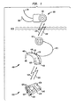
- FIG. 1 is a perspective view of a partially implantable hearing aid system in accordance with one embodiment of the present invention
- FIG. 2 is a perspective view of a partially implantable hearing aid system comprising two implantable devices (cochlear implants) and two BTE devices, in accordance with one embodiment of the present invention
- FIG. 3 is a perspective view of a BTE device with an RF antenna and a replaceable power supply, in accordance with one embodiment of the present invention
- FIG. 4 is a perspective view of a partially implantable hearing aid system comprising a remote unit with a digital interface for e.g. wired connection to a PC and a RF wireless interface for communication with a second device, being a BTE device;
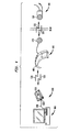
- FIG. 5 fig 5A and FIG. 5B are block diagrams of embodiments of a remote unit and a BTE device, respectively, each comprising means for operating a wireless burst transmission link in accordance with one embodiment of the present invention
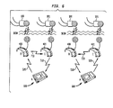
- FIG. 6 is a perspective view of a communication arrangement within a partially implantable hearing aid system comprising a remote unit, two BTE devices, and two cochlear implants, in accordance with one embodiment of the present invention.
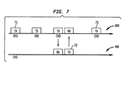
- FIG. 7 is a schematic view of a transmission protocol for wireless communication according to one embodiment of the present invention.
- Embodiments of the present invention are generally directed toward providing an energy efficient method of wireless communication between hearing aid devices of a hearing aid system.
- a first device selects a frequency channel for bidirectional wireless communication from a predefined series of frequency channels.
- a second device transmits a command signal repeatedly over the series of frequency channels until it transmits the command signal over the frequency channel selected by the first device. Subsequent commands send by the second device to the first device are initially transmitted over the selected frequency channel.
- FIG. 1 A perspective view of a partially implantable hearing aid system is shown in FIG. 1 .
- the hearing aid system comprises three different primary devices: a behind-the-ear device 400, an implantable hearing aid device 100 and a remote unit 600.
- the hearing air system converts airborne sound waves captured by a microphone into stimuli signals applied to the middle ear, inner ear or brainstem by means of an electrode or actuator.
- the implantable hearing aid device 100 is an active electronic medical device typically implanted under the human skin near the left or right ear.
- Implantable device 100 comprises an implantable electrode 170 that stimulates by electrical signals the auditory nerves of the cochlea or brainstem.
- a mechanical implantable actuator 180 stimulating middle or inner ear parts may be placed as an additional or alternative functional element.
- the main assembly of behind-the-ear device 400 comprises a main housing, a carrier for plug-in modules such as battery packs 460, an ear hook 490 and a headpiece 470.
- the housing is formed of metallic material, ceramic material, polymeric material or a combination of them.
- Implantable device 100 further comprises a microphone 440, a human user interface with control buttons 420 and small display 430, digital and analogue inputs and outputs 450, a signal processor with memory and a battery slot for a replaceable part 460 such as a carrier 462 for Zn-Air batteries or a rechargeable Lithium-ion battery pack 461.
- BTE device 400 is configured to accept a removable connection to a headpiece 470 via a cable 471.
- Headpiece 470 comprises an antenna coil or closed wire loop that is capable of transmitting and receiving signals to/from a complementary antenna 160 of implantable device 100.
- Such forward 310 and backward 320 telemetry links between BTE device 400 and implantable hearing aid device 100 are based on magnetic induction coupling, utilizing the non-propagating quasi-static magnetic field. The magnetic field may have a very high roll-off behaviour as a function of distance.
- Forward link 310 additionally may supply power to the implant.
- BTE device 400 is additionally configured to receive and transmit telemetry signals over a wireless electromagnetic RF link 510 and 520, based on electromagnetic field propagation.
- the power for a plane wave in the far field rolls-off as one over the distance from the source squared.
- This second type of communication link enables a larger wireless communication range. Therefore BTE device 400 may use an appropriate monopole, dipole or any other suitable antenna 480.
- Antenna 480 may advantageously be integrated in ear hook 490. This is illustrated in FIG. 3 .
- Wires 482 provide coupling of antenna 480 to the printed circuit board (PCB) of the BTE device.
- PCB printed circuit board
- This latter placement of antenna 480 has the advantage that no additional space is required for the antenna and its location is advantageous on the subject of RF emission efficiency at higher frequencies, e.g. the 2.4 GHz unlicensed frequency band.
- Alternative locations for antenna placement may be implemented in alternative embodiments of the present invention.
- the antenna is placed within a removable power supply (battery) module 465.
- the extended range of operation obtainable with this type of coil-less link 510, 520 may be beneficial for parents wanting to verify or even control their child's hearing aid system, which may be a partially implanted system.
- This verification or control may be performed through a remote unit 600 which communicates with the BTE device 400 via wireless link 510 and 520.
- the RF link 510, 520 allows operating the remote unit a comfortable distance away from the BTE device.
- the remote unit may report on the status of the partially implanted system (battery level, operating status of the link between BTE and cochlear implant, etc.).
- FIG. 3 is a perspective view of one embodiment of behind-the-ear device 400.
- this embodiment of behind-the-ear device 400 comprises a compartment 460 for plug-in modules.
- the illustrated plug-in modules may be a battery carrier 463 for one Zn-Air battery or a carrier 462 for two Zn-Air batteries, a rechargeable battery module 461, or any combination of preceding modules.
- the plug-in module may comprise an integrated wired interface 464, or wireless interface 465 enabling remote connectivity with peripheral data devices 1000 or 1010.
- FIG. 1 depicts one embodiment of remote unit 600 that is dimensioned to be a handheld device.
- Remote unit 600 comprises a receiver and transmitter system with antenna 610 for bidirectional wireless communication with BTE device 400, using links 510 and 520.
- Links 510 and 520 may be based on electromagnetic field propagation.
- wireless link 510, 520 is an electromagnetic RF link.
- Remote unit 600 also comprises a microphone system 640, a human user interface with control buttons 620 and display 630, digital and analogue inputs and outputs 650, a microcontroller, memory and replaceable batteries.
- Remote unit 600 may also comprise an external digital interface port 660, such as a USB interface, connectable with a cable 800 to a personal home computer 900 or hand-palm computer ( FIG. 4 ).
- an external digital interface port 660 such as a USB interface
- This enables downloads or uploads of data between PC and BTE, PC and remote unit or PC and implant for changing firmware, software, maps or parameters.
- the additional advantage of interface port 660 is that the user of the system is able to do this at home with the same remote device if and when desired.
- BTE device 400 is configured to select a frequency channel for the link 510, 520 from a predefined series of different frequency channels.
- the frequency channel the BTE may select may be an interference free channel or the least interfered channel from the predefined series.
- the choice of which frequency channel to select for the wireless link 510, 520 is preferably a decision made solely by BTE device 400.
- the selected frequency channel will be the only frequency channel on which the BTE device "listens" to another device, such as a remote unit 600 at a given instant of time.
- BTE device 400 is configured to respond to the other device (e.g. remote unit 600) on the selected frequency channel.
- BTE device 400 may choose to change its selection and to select another frequency channel from the series, e.g. when the frequency channel becomes highly interfered. BTE device 400 may be arranged to select the least interfered frequency channel. Hence, the selected frequency channel is not a fixed frequency channel.
- Remote unit 600 does not a priori contain information regarding which frequency channel BTE device 400 has selected for wireless link 510, 520. Therefore, remote unit 600 may be configured to use different frequency channels for wireless link 510, 520. Those different frequency channels may be the same predefined series of frequency channels from BTE device 400.
- Remote unit 600 is configured to transmit commands to BTE device 400 over wireless link 520.
- remote unit 600 does not a priori contain information regarding which frequency channel BTE device 400 is currently listening, the following protocol is set up for the transmission of a command from remote unit 600 to BTE device 400, in accordance with one embodiment of the present invention. This embodiment of the protocol is illustrated in FIG. 7 .
- Remote unit 600 transmits a command 71 over link 520 using a first (physical) frequency channel CH1. Thereafter, remote unit 600 awaits for predefined time whether a reply signal is received. If CH1 is not the frequency channel on which BTE device 400 is currently listening, remote unit 600 will not receive a reply signal on CH1, and selects a second frequency channel CH2. The same command 71 is transmitted over second frequency channel CH2. Remote unit 600 awaits during the predefined time whether a reply signal is received. If no reply signal is received, remote unit 600 selects a third frequency channel CH3 and transmits the same command 71 over the third frequency channel. Assuming that CH3 is the frequency channel selected by BTE device 400 at that time, then BTE device 400 will receive the command 71 transmitted over channel CH3.
- BTE device 400 then transmits a reply signal 72 over the same frequency channel CH3 over link 510, the reply signal being received by the remote unit 600.
- remote unit 600 Upon reception of reply signal 72, remote unit 600 contains information indicating that CH3 is the frequency channel that is currently selected by BTE device 400.
- remote unit 600 For the transmission of a next command 73, remote unit 600 uses physical frequency channel CH3 as a preferred frequency channel for initial transmission. Hence, frequency channel CH3 will be the first channel over which remote unit 600 transmits command 73. Should BTE device 400 in the meantime have changed the frequency channel, then remote unit 600 follows the same protocol as above for transmission of the command. Hence, if after a predefined wait time no reply signal is received on CH3 for command 73, another frequency channel is selected by the remote unit (e.g. CH1) and command 73 is transmitted over that frequency channel and so on.
- CH1 the remote unit
- remote unit 600 may be considered a master for commands and BTE device 400 a slave for commands.
- BTE device 400 is however a master for the selection of frequency channels and remote unit 600 is a slave for the selection of frequency channels.
- remote unit 600 may be arranged to transmit a command 71 multiple times over a same frequency channel CH1 before switching to a second frequency channel CH2.
- the transmission protocol for wireless link 510, 520 allows for the saving of power by BTE device 400.
- the receiver (and transmitter) unit of BTE device 400 for link 510, 520 may remain idle as long as no command is received on the selected frequency channel (e.g. CH3 in FIG. 7 ).
- the transmission of data over link 510, 520 may be arranged as a burst transmission at very high symbol rate or bit rate. A burst transmission at high bit rate allows to lower the duty cycle of the RF transmissions.
- the data transmitted over link 510, 520 may be digitally modulated.
- digital modulation an analog carrier signal is modulated by a digital bit stream.
- Digital modulation methods that may be implemented in embodiments of the present invention include but are not limited to phase shift keying, frequency shift keying, amplitude shift keying, minimum shift keying, on/off keying, orthogonal frequency division multiplexing and quadrature amplitude modulation.
- Burst transmissions are transmissions that combine a very high data signalling (symbol) rate with very short transmission times. Each burst hence has a limited duration. In between different bursts, the transmitter may be idle and draw only a fraction of the power drawn when transmitting the bursts. Typical total transmission times of burst transmissions according to the invention may fall in the range between 0.1% and 50%. Burst transmissions are digitally modulated transmissions.
- the use of the above transmission protocol is not limited to the communication between a BTE device and a remote unit, but may also be implemented, for example, for the communication between a BTE device 400 and a cochlear implant 100.
- BTE device 400 and remote unit 600 are provided with the means required for operating the wireless communication link 510, 520 as a digitally modulated, high bit rate burst transmission link.
- Remote unit 600 may draw energy from a replaceable battery system 670 and comprises a centralized microcontroller 671 with limited persistent and non-persistent memory 672, a system clock 672, digital interfaces 621 and 661, analogue interfaces 641, 653 and 654, an analog source switch 642, a digital to analog converter 655, an analog to digital converter 643 and a digital modulated RF transmitter 612 and RF receiver 611 block.
- the analog interfaces are represented in FIGS. 5A and 5B as signal conditioning blocks, including level shifters, analogue amplifiers, attenuators and filters.
- a radio control unit 613 controls the timing and synchronisation over the incoming and outgoing data packets of the wireless RF link.
- An accurate clock source 614 provides the transmitter and receiver with a stable communication channel with predefined timing slots for RF burst transmissions and receptions. Those transmissions and receptions comprise telemetry signals such as control data, command data, program data and signalling data.
- radio control unit 613 is arranged for changing the frequency channel of transmission of a command through transmitter 612 and antenna 610.
- Clock source 614 may be used for generating accurate frequencies for the wireless link.
- the centralized microcontroller is configured to translate the incoming analog and digital interface and control signals 620 to a format adapted to transmitter 612. Furthermore, it is configured to interpret and adapt the incoming data from receiver 611 and to transfer it to the respective outgoing interfaces such as a display 630, a digital data interface output or analog output 652. In order to further reduce energy consumption, the microcontroller works on a system clock 672 at low speed when idle or in sleep mode.
- BTE device 400 of FIG. 5B operates on a replaceable battery system plugged into compartment 460 and comprises a high intelligent signal processor 472 with sufficient persistent and non-persistent memory 474, a system clock 473, a digital interface 421, analog interfaces 441, 453, 454, an analog source switch 442, a digital to analog converter 455, an analog to digital converter 443 and a digital modulated RF transmitter 482 and RF receiver 481 block.
- the analog interfaces are represented as signal conditioning blocks, including level shifters, analog amplifiers, attenuators and filters.
- a radio control unit 483 in BTE device 400 controls the timing and synchronisation over the incoming and outgoing data packets of the wireless RF link.
- An accurate clock source 484 provides the transmitter and receiver with a stable communication channel with predefined timing slots for RF burst transmissions and receptions. Those transmissions and receptions may comprise telemetry signals such as control data, command data, program data and signalling data.
- Radio control unit 483 is arranged to select a frequency channel from a predefined series of frequency channels for communication over wireless link 510 and 520.
- Clock source 484 may be used for generating accurate frequencies for the wireless link.
- the receiver, transmitter and radio control unit of BTE device 400 and/or remote unit 600 may be implemented on a single ASIC (application specific integrated circuit).
- ASIC application specific integrated circuit
- BTE device 400 mainly processes (meaning filtering, encoding, converting etc.) the airborne auditory signals captured from local microphone 440 or analogue interfaces, or remote microphone 640 or analog interfaces.
- the converted signals are transferred via a transcutaneous magnetic link to implant 100 using a magnetic transceiver 471 and antenna coil 470.
- BTE device 400 may comprise a sound processor unit.
- BTE device 400 is also arranged to process the incoming data from the transcutaneous magnetic link transceiver 471 and receiver 481. Depending on predefined events or timings, BTE device 400 may transfer relevant data to the local digital interface 421, display 430 or to the RF transmitter 482.
- FIG. 6 shows an embodiment of a method of transferring telemetry signals over a RF wireless communication link for a bilateral hearing aid system, which optimizes the overall system energy consumption.
- the recipient has two cochlear implants 100 and 101 implanted with corresponding BTE devices 400 and 401 respectively.
- the two hearing aid devices (BTE devices with cochlear implants) are controlled by a remote unit 600.
- Remote unit 600 is referred to as device 'A'
- a first behind-the-ear device 400 and second behind-the-ear device 401 are referred to as device 'B' and device 'C' respectively.
- the scheme depicted on the left-hand side of FIG. 6 shows a remote unit A initiating a link. It sends a forward telemetry signal unidirectionally to device B via link 520.
- Link 520 may be operated according to the protocol as illustrated in FIG. 7 .
- Device B may send a reply signal upon reception of the telemetry signal in order to acknowledge that the signal has been received.
- Device B may also not send that reply signal.
- device B sends this telemetry signal unidirectionally, unmodified or modified in a predetermined manner to device C via link 710.
- Devices B and C may operate on the same frequency channel for link 710 in order to limit the number of bursts.
- Link 710 may operate over a fixed frequency channel, or over different frequency channels.
- device C sends this telemetry signal unidirectionally, unmodified or modified in a predetermined manner to the remote unit A via link 510.
- the signal that device C sends to device A may serve in one embodiment as a reply signal 72. It may be sent over a same frequency channel as the initial telemetry signal over link 520.
- the remote unit A as initiator, internally validates the backward telemetry signal of device C with its forward telemetry signal for acknowledgement that data is uncorrupted and was accepted by devices B and C. If such a backward telemetry signal is not received by device A in due time, device A may select another frequency channel for link 520 and send the forward telemetry signal again.
- An advantage of the above method of communication with three devices is that for sending a command from A to the other two devices B and C and for receiving an acknowledgement only three packets may be needed, whereas in case of mere direct communication with both devices A-B and A-C four packets would be needed for achieving the same.
- the amount of transmitted data is hence reduced and so is also the energy consumption.
- the communication from device B to device C may additionally be used to transmit bilateral information.
- FIG. 6 depicts an inversed situation, where a forward telemetry signal is first sent from remote unit A to BTE device C, then from BTE device C to BTE device B and finally from BTE device B to remote unit A.
- the hearing aid system comprising cochlear implants 100 and 101, BTE devices 400 and 401 and remote unit 600 may be arranged to operate according to only one or both schemes of FIG. 6 .
- RF communication links 510, 520, 710 and 720 may operate according to the burst transmission scheme of the invention.
- the advantage of the schemes of FIG. 6 lies in the fact that, instead of sending a message to each BTE device separately and waiting for both to acknowledge separately, as shown in FIG. 2 , only one message is sent and received by the remote unit. This saves energy since only one transmission and reception timeslot is used, or transmitter and receiver circuitry power-on times are reduced.
Landscapes
- Health & Medical Sciences (AREA)
- Engineering & Computer Science (AREA)
- Otolaryngology (AREA)
- General Health & Medical Sciences (AREA)
- Signal Processing (AREA)
- Acoustics & Sound (AREA)
- Physics & Mathematics (AREA)
- Neurosurgery (AREA)
- Radiology & Medical Imaging (AREA)
- Veterinary Medicine (AREA)
- Public Health (AREA)
- Animal Behavior & Ethology (AREA)
- Life Sciences & Earth Sciences (AREA)
- Nuclear Medicine, Radiotherapy & Molecular Imaging (AREA)
- Biomedical Technology (AREA)
- Computer Networks & Wireless Communication (AREA)
- Prostheses (AREA)
- Radio Transmission System (AREA)
Abstract
transmitting a signal from the first device to the second device;
receiving the signal by the second device, optionally modifying the signal in a predetermined manner and transmitting the signal, unmodified or modified in a predetermined manner, from the second device to the third device;
receiving the signal by the third device, optionally modifying the signal in a predetermined manner and transmitting the signal, unmodified or modified in a predetermined manner, from the third device to the first device and
receiving the signal by the first device and comparing the signal that is received with the signal that was transmitted.
Description
- The present invention relates generally to hearing aid systems and, more particularly, to wireless communication between components of a hearing aid system.
- Hearing aid systems typically include systems which are non-implantable as well as systems which are partially implantable. A partially implantable hearing aid system typically comprises an implantable device that delivers direct or indirect mechanical or electrical stimulation to the inner or middle ear. Such hearing aid systems also include one or more external devices which process auditory signals and transfer a representation of the auditory signals to the implanted device. Such an external device typically includes a microphone that converts auditory signals into an electrical signal, and a sound processor that processes the electrical signal to generate an encoded output signal. The encoded output signal is then wirelessly transcutaneously transmitted to the implantable device.
- If the hearing aid system is a cochlcar™ implant ( commonly referred to as a cochlear™ device, cochlear™ implant device, cochlear™ implant system, and the like; hereinafter "cochlear implant"), the encoded signals are delivered to an implantable device commonly referred to as a receiver/stimulator unit. The stimulator unit generates electrical stimulation signals which are delivered to the auditory nerves by means of an electrode carrier member implanted in the recipient's cochlea. This allows the recipient's brain to perceive a hearing sensation resembling the natural hearing sensation normally delivered by the auditory nerve. When the auditory nerve is absent or inoperative, brainstem stimulation may be applied.
- External electronic devices comprising auditory transducers, signal processors and memory, user interfaces and batteries support the implantable devices of the hearing aid system (also referred to herein as the implant). Some of these external devices are miniaturized and worn behind the ear of the recipient. As such, they are hereafter referred to as behind-the-ear (BTE) devices or sound processor units.
- Since hearing implants contain active components, they are provided with a battery. The behind-the-ear device has an attached headpiece including a coil for transferring power to the implant by magnetic induction. It is known to provide the behind-the-ear device with a slot or compartment for a power supply module. Power supply modules with different types of batteries may be inserted into that compartment. By way of example, the power supply module may comprise a carrier for replaceable Zn-Air batteries or a fixed rechargeable battery. This arrangement enables the batteries to be readily replaced.
- Some hearing aid systems include remote units which are operable coupled to the BTE devices. Such remote units may comprise user interfaces which allow the recipient and/or the carer to customize the cochlear implant, as well as to gain feedback concerning the operating status of the hearing aid system, to adjust the volume or sensitivity of the sound processor, to select which speech program is to be used, etc. A remote unit may also comprise an easy-to-use human interface. A remote unit with larger control buttons for controlling the implant, a clearly displayed status indication and connectivity to a personal computer are additional benefits. The remote unit may communicate wirelessly with the BTE device. Therefore, the remote unit may be provided with a RF signal transmitter and/or receiver and with a RF antenna. Wireless hearing aid devices enlarge possibilities and improve ease of use for the recipient, carer or clinicians.
- In accordance with one aspect of the present invention, there is disclosed a hearing aid comprising a first device and a second device arranged for receiving commands from the first device, wherein: the first and the second devices each comprise a transmitter and receiver arranged for communication over a wireless link, the second device is configured to select a frequency channel for bidirectional wireless communication from a predefined series of frequency channels, the first device is configured to transmit a command signal repeatedly over a plurality of frequency channels which comprises the frequency channel selected by the second device, and the first device is configured to initiate transmission of a subsequent command over the frequency channel selected by the second device.
- According to another aspect of the present invention, there is disclosed a method of wireless communication between a first device and a second device of a hearing aid system, the method comprising: selecting, by the second device, a frequency channel for bidirectional wireless communication from a predefined series of frequency channels, preparing in the first device a command for the second device, sending the command from the first device repeatedly over a plurality of frequency channels, the plurality of frequency channels comprising the frequency channel selected by the second device, until a reply signal is received by the first device and using the frequency channel selected by the second device as the initial transmission frequency for a subsequent command sent by the first device to the second device.
- According to a further aspect of the present invention, there is disclosed a method of wireless communication between multiple devices of a hearing aid system having first, second and third devices, comprising: transmitting a signal from the first device to the second device, receiving the signal by the second device, optionally modifying the signal in a predetermined manner and transmitting the signal, unmodified or modified in a predetermined manner, from the second device to the third device, receiving the signal by the third device, optionally modifying the signal in a predetermined manner and transmitting the signal, unmodified or modified in a predetermined manner, from the third device to the first device and receiving the signal by the first device and comparing the signal that is received with the signal that was transmitted.
- Embodiments of the present invention are described below with reference to the following figures in which:
-
FIG. 1 is a perspective view of a partially implantable hearing aid system in accordance with one embodiment of the present invention; -
FIG. 2 is a perspective view of a partially implantable hearing aid system comprising two implantable devices (cochlear implants) and two BTE devices, in accordance with one embodiment of the present invention; -
FIG. 3 is a perspective view of a BTE device with an RF antenna and a replaceable power supply, in accordance with one embodiment of the present invention; -
FIG. 4 is a perspective view of a partially implantable hearing aid system comprising a remote unit with a digital interface for e.g. wired connection to a PC and a RF wireless interface for communication with a second device, being a BTE device; -
FIG. 5 fig 5A andFIG. 5B are block diagrams of embodiments of a remote unit and a BTE device, respectively, each comprising means for operating a wireless burst transmission link in accordance with one embodiment of the present invention; -
FIG. 6 is a perspective view of a communication arrangement within a partially implantable hearing aid system comprising a remote unit, two BTE devices, and two cochlear implants, in accordance with one embodiment of the present invention; and -
FIG. 7 is a schematic view of a transmission protocol for wireless communication according to one embodiment of the present invention. - Embodiments of the present invention are generally directed toward providing an energy efficient method of wireless communication between hearing aid devices of a hearing aid system. A first device selects a frequency channel for bidirectional wireless communication from a predefined series of frequency channels. A second device transmits a command signal repeatedly over the series of frequency channels until it transmits the command signal over the frequency channel selected by the first device. Subsequent commands send by the second device to the first device are initially transmitted over the selected frequency channel.
- A perspective view of a partially implantable hearing aid system is shown in
FIG. 1 . The hearing aid system comprises three different primary devices: a behind-the-ear device 400, an implantablehearing aid device 100 and aremote unit 600. The hearing air system converts airborne sound waves captured by a microphone into stimuli signals applied to the middle ear, inner ear or brainstem by means of an electrode or actuator. - The implantable
hearing aid device 100 is an active electronic medical device typically implanted under the human skin near the left or right ear.Implantable device 100 comprises animplantable electrode 170 that stimulates by electrical signals the auditory nerves of the cochlea or brainstem. Depending on cause of recipient's deafness, a mechanicalimplantable actuator 180 stimulating middle or inner ear parts may be placed as an additional or alternative functional element. - In one embodiment, the main assembly of behind-the-
ear device 400 comprises a main housing, a carrier for plug-in modules such asbattery packs 460, anear hook 490 and aheadpiece 470. In certain embodiments, the housing is formed of metallic material, ceramic material, polymeric material or a combination of them.Implantable device 100 further comprises amicrophone 440, a human user interface withcontrol buttons 420 andsmall display 430, digital and analogue inputs andoutputs 450, a signal processor with memory and a battery slot for areplaceable part 460 such as acarrier 462 for Zn-Air batteries or a rechargeable Lithium-ion battery pack 461. - BTE
device 400 is configured to accept a removable connection to aheadpiece 470 via acable 471.Headpiece 470 comprises an antenna coil or closed wire loop that is capable of transmitting and receiving signals to/from acomplementary antenna 160 ofimplantable device 100. Such forward 310 and backward 320 telemetry links betweenBTE device 400 and implantablehearing aid device 100 are based on magnetic induction coupling, utilizing the non-propagating quasi-static magnetic field. The magnetic field may have a very high roll-off behaviour as a function of distance.Forward link 310 additionally may supply power to the implant. - BTE
device 400 is additionally configured to receive and transmit telemetry signals over a wirelesselectromagnetic RF link device 400 may use an appropriate monopole, dipole or any othersuitable antenna 480.Antenna 480 may advantageously be integrated inear hook 490. This is illustrated inFIG. 3 . -
Wires 482 provide coupling ofantenna 480 to the printed circuit board (PCB) of the BTE device. This latter placement ofantenna 480 has the advantage that no additional space is required for the antenna and its location is advantageous on the subject of RF emission efficiency at higher frequencies, e.g. the 2.4 GHz unlicensed frequency band. Alternative locations for antenna placement may be implemented in alternative embodiments of the present invention. For example, in one embodiment, the antenna is placed within a removable power supply (battery)module 465. - The extended range of operation obtainable with this type of
coil-less link remote unit 600 which communicates with theBTE device 400 viawireless link RF link -
FIG. 3 is a perspective view of one embodiment of behind-the-ear device 400. this embodiment of behind-the-ear device 400 comprises acompartment 460 for plug-in modules. The illustrated plug-in modules may be abattery carrier 463 for one Zn-Air battery or acarrier 462 for two Zn-Air batteries, arechargeable battery module 461, or any combination of preceding modules. The plug-in module may comprise an integratedwired interface 464, orwireless interface 465 enabling remote connectivity withperipheral data devices -
FIG. 1 depicts one embodiment ofremote unit 600 that is dimensioned to be a handheld device.Remote unit 600 comprises a receiver and transmitter system withantenna 610 for bidirectional wireless communication withBTE device 400, usinglinks Links wireless link Remote unit 600 also comprises amicrophone system 640, a human user interface withcontrol buttons 620 anddisplay 630, digital and analogue inputs and outputs 650, a microcontroller, memory and replaceable batteries. -
Remote unit 600 may also comprise an externaldigital interface port 660, such as a USB interface, connectable with acable 800 to apersonal home computer 900 or hand-palm computer (FIG. 4 ). This enables downloads or uploads of data between PC and BTE, PC and remote unit or PC and implant for changing firmware, software, maps or parameters. The additional advantage ofinterface port 660 is that the user of the system is able to do this at home with the same remote device if and when desired. -
BTE device 400 is configured to select a frequency channel for thelink wireless link BTE device 400. The selected frequency channel will be the only frequency channel on which the BTE device "listens" to another device, such as aremote unit 600 at a given instant of time.BTE device 400 is configured to respond to the other device (e.g. remote unit 600) on the selected frequency channel. -
BTE device 400 may choose to change its selection and to select another frequency channel from the series, e.g. when the frequency channel becomes highly interfered.BTE device 400 may be arranged to select the least interfered frequency channel. Hence, the selected frequency channel is not a fixed frequency channel. -
Remote unit 600 does not a priori contain information regarding which frequencychannel BTE device 400 has selected forwireless link remote unit 600 may be configured to use different frequency channels forwireless link BTE device 400. -
Remote unit 600 is configured to transmit commands toBTE device 400 overwireless link 520. Asremote unit 600 does not a priori contain information regarding which frequencychannel BTE device 400 is currently listening, the following protocol is set up for the transmission of a command fromremote unit 600 toBTE device 400, in accordance with one embodiment of the present invention. This embodiment of the protocol is illustrated inFIG. 7 . -
Remote unit 600 transmits acommand 71 overlink 520 using a first (physical) frequency channel CH1. Thereafter,remote unit 600 awaits for predefined time whether a reply signal is received. If CH1 is not the frequency channel on whichBTE device 400 is currently listening,remote unit 600 will not receive a reply signal on CH1, and selects a second frequency channel CH2. Thesame command 71 is transmitted over second frequency channel CH2.Remote unit 600 awaits during the predefined time whether a reply signal is received. If no reply signal is received,remote unit 600 selects a third frequency channel CH3 and transmits thesame command 71 over the third frequency channel. Assuming that CH3 is the frequency channel selected byBTE device 400 at that time, thenBTE device 400 will receive thecommand 71 transmitted over channel CH3.BTE device 400 then transmits areply signal 72 over the same frequency channel CH3 overlink 510, the reply signal being received by theremote unit 600. Upon reception ofreply signal 72,remote unit 600 contains information indicating that CH3 is the frequency channel that is currently selected byBTE device 400. - For the transmission of a
next command 73,remote unit 600 uses physical frequency channel CH3 as a preferred frequency channel for initial transmission. Hence, frequency channel CH3 will be the first channel over whichremote unit 600 transmitscommand 73. ShouldBTE device 400 in the meantime have changed the frequency channel, thenremote unit 600 follows the same protocol as above for transmission of the command. Hence, if after a predefined wait time no reply signal is received on CH3 forcommand 73, another frequency channel is selected by the remote unit (e.g. CH1) andcommand 73 is transmitted over that frequency channel and so on. - Hence, in the protocol described above,
remote unit 600 may be considered a master for commands and BTE device 400 a slave for commands.BTE device 400 is however a master for the selection of frequency channels andremote unit 600 is a slave for the selection of frequency channels. - In another embodiment,
remote unit 600 may be arranged to transmit acommand 71 multiple times over a same frequency channel CH1 before switching to a second frequency channel CH2. - The transmission protocol for
wireless link BTE device 400. The receiver (and transmitter) unit ofBTE device 400 forlink FIG. 7 ). Moreover, the transmission of data overlink - The data transmitted over
link - Applying the kind of link described above for bidirectional wireless communication between
BTE device 400 andremote unit 600 reduces overall system energy consumption, even for higher bit rate transfers. Additionally, energy consumption is reduced by the limited total transmission time of burst transmissions. Burst transmissions are transmissions that combine a very high data signalling (symbol) rate with very short transmission times. Each burst hence has a limited duration. In between different bursts, the transmitter may be idle and draw only a fraction of the power drawn when transmitting the bursts. Typical total transmission times of burst transmissions according to the invention may fall in the range between 0.1% and 50%. Burst transmissions are digitally modulated transmissions. - The use of the above transmission protocol is not limited to the communication between a BTE device and a remote unit, but may also be implemented, for example, for the communication between a
BTE device 400 and acochlear implant 100. - In the embodiment of
FIGS. 5A and5B ,BTE device 400 andremote unit 600 are provided with the means required for operating thewireless communication link Remote unit 600 may draw energy from areplaceable battery system 670 and comprises acentralized microcontroller 671 with limited persistent andnon-persistent memory 672, asystem clock 672,digital interfaces analogue interfaces analog source switch 642, a digital toanalog converter 655, an analog todigital converter 643 and a digital modulatedRF transmitter 612 andRF receiver 611 block. The analog interfaces are represented inFIGS. 5A and5B as signal conditioning blocks, including level shifters, analogue amplifiers, attenuators and filters. - A
radio control unit 613 controls the timing and synchronisation over the incoming and outgoing data packets of the wireless RF link. Anaccurate clock source 614 provides the transmitter and receiver with a stable communication channel with predefined timing slots for RF burst transmissions and receptions. Those transmissions and receptions comprise telemetry signals such as control data, command data, program data and signalling data. Furthermore,radio control unit 613 is arranged for changing the frequency channel of transmission of a command throughtransmitter 612 andantenna 610.Clock source 614 may be used for generating accurate frequencies for the wireless link. - The centralized microcontroller is configured to translate the incoming analog and digital interface and
control signals 620 to a format adapted totransmitter 612. Furthermore, it is configured to interpret and adapt the incoming data fromreceiver 611 and to transfer it to the respective outgoing interfaces such as adisplay 630, a digital data interface output oranalog output 652. In order to further reduce energy consumption, the microcontroller works on asystem clock 672 at low speed when idle or in sleep mode. -
BTE device 400 ofFIG. 5B operates on a replaceable battery system plugged intocompartment 460 and comprises a highintelligent signal processor 472 with sufficient persistent andnon-persistent memory 474, asystem clock 473, adigital interface 421, analog interfaces 441, 453, 454, ananalog source switch 442, a digital toanalog converter 455, an analog todigital converter 443 and a digital modulatedRF transmitter 482 andRF receiver 481 block. The analog interfaces are represented as signal conditioning blocks, including level shifters, analog amplifiers, attenuators and filters. - Analogously to
remote unit 600, aradio control unit 483 inBTE device 400 controls the timing and synchronisation over the incoming and outgoing data packets of the wireless RF link. Anaccurate clock source 484 provides the transmitter and receiver with a stable communication channel with predefined timing slots for RF burst transmissions and receptions. Those transmissions and receptions may comprise telemetry signals such as control data, command data, program data and signalling data.Radio control unit 483 is arranged to select a frequency channel from a predefined series of frequency channels for communication overwireless link Clock source 484 may be used for generating accurate frequencies for the wireless link. - The receiver, transmitter and radio control unit of
BTE device 400 and/orremote unit 600 may be implemented on a single ASIC (application specific integrated circuit). -
BTE device 400 mainly processes (meaning filtering, encoding, converting etc.) the airborne auditory signals captured fromlocal microphone 440 or analogue interfaces, orremote microphone 640 or analog interfaces. The converted signals are transferred via a transcutaneous magnetic link to implant 100 using amagnetic transceiver 471 andantenna coil 470.BTE device 400 may comprise a sound processor unit. - Furthermore,
BTE device 400 is also arranged to process the incoming data from the transcutaneousmagnetic link transceiver 471 andreceiver 481. Depending on predefined events or timings,BTE device 400 may transfer relevant data to the localdigital interface 421,display 430 or to theRF transmitter 482. - When a recipient is hearing impaired on both ears and has at least two hearing aid devices, one for each ear, the present invention provides a method of reducing the energy consumption of the total system.
FIG. 6 shows an embodiment of a method of transferring telemetry signals over a RF wireless communication link for a bilateral hearing aid system, which optimizes the overall system energy consumption. In the present embodiment, the recipient has twocochlear implants corresponding BTE devices remote unit 600.Remote unit 600 is referred to as device 'A', a first behind-the-ear device 400 and second behind-the-ear device 401, are referred to as device 'B' and device 'C' respectively. - The scheme depicted on the left-hand side of
FIG. 6 shows a remote unit A initiating a link. It sends a forward telemetry signal unidirectionally to device B vialink 520.Link 520 may be operated according to the protocol as illustrated inFIG. 7 . Device B may send a reply signal upon reception of the telemetry signal in order to acknowledge that the signal has been received. Device B may also not send that reply signal. Subsequently, device B sends this telemetry signal unidirectionally, unmodified or modified in a predetermined manner to device C vialink 710. Devices B and C may operate on the same frequency channel forlink 710 in order to limit the number of bursts.Link 710 may operate over a fixed frequency channel, or over different frequency channels. Next, device C sends this telemetry signal unidirectionally, unmodified or modified in a predetermined manner to the remote unit A vialink 510. The signal that device C sends to device A may serve in one embodiment as areply signal 72. It may be sent over a same frequency channel as the initial telemetry signal overlink 520. The remote unit A, as initiator, internally validates the backward telemetry signal of device C with its forward telemetry signal for acknowledgement that data is uncorrupted and was accepted by devices B and C. If such a backward telemetry signal is not received by device A in due time, device A may select another frequency channel forlink 520 and send the forward telemetry signal again. - An advantage of the above method of communication with three devices is that for sending a command from A to the other two devices B and C and for receiving an acknowledgement only three packets may be needed, whereas in case of mere direct communication with both devices A-B and A-C four packets would be needed for achieving the same. The amount of transmitted data is hence reduced and so is also the energy consumption. Moreover, the communication from device B to device C may additionally be used to transmit bilateral information.
- The drawing on the right-hand side of
FIG. 6 depicts an inversed situation, where a forward telemetry signal is first sent from remote unit A to BTE device C, then from BTE device C to BTE device B and finally from BTE device B to remote unit A. The hearing aid system comprisingcochlear implants BTE devices remote unit 600 may be arranged to operate according to only one or both schemes ofFIG. 6 .RF communication links - The advantage of the schemes of
FIG. 6 lies in the fact that, instead of sending a message to each BTE device separately and waiting for both to acknowledge separately, as shown inFIG. 2 , only one message is sent and received by the remote unit. This saves energy since only one transmission and reception timeslot is used, or transmitter and receiver circuitry power-on times are reduced. -
- 1. A hearing prosthesis comprising a first device and a second device arranged for receiving commands from said first device, wherein:
- said first and the second devices each comprise a transmitter and receiver system configured for communication over a wireless communications link;
- said second device is configured to select a frequency channel for bidirectional wireless communication from a predefined series of frequency channels;
- said first device is configured to transmit a command signal repeatedly over a plurality of frequency channels comprising the frequency channel selected by said second device; and
- said first device is further configured to initiate transmission of a subsequent command over said frequency channel selected by said second device.
- 2. The hearing prosthesis of embodiment 1, wherein said second device is further configured to transmit a reply signal over said frequency channel selected by said second device.
- 3. The hearing prosthesis of embodiment 1, wherein said receiver system of said second device is configured to be idle between two consecutively received commands.
- 4. The hearing prosthesis according to embodiment 1, wherein said wireless link is an electromagnetic RF link.
- 5. The hearing prosthesis of embodiment 1, wherein said wireless link is a magnetic induction RF link.
- 6. The hearing prosthesis of embodiment 1, wherein said communication over said wireless link is arranged in packets or bursts at a symbol rate greater than or equal to 100K symbols per second.
- 7. The hearing prosthesis of embodiment 1, wherein said first device comprises a digital modulator coupled to said transmitter system of said first device and a digital demodulator coupled to said receiver system of said first device, and wherein said second device comprises a digital modulator coupled to said transmitter system of said second device and a digital demodulator coupled to said receiver system of said second device.
- 8. The hearing prosthesis of embodiment 1, wherein said second device is configured to select the least interfered frequency channel of the predefined series of frequency channels for bidirectional wireless communication.
- 9. The hearing prosthesis of embodiment 1, wherein said transmitter and said receiver of said first and second devices are embodied in an CMOS integrated circuit.
- 10. The hearing prosthesis of embodiment 1, wherein said first device is a remote control unit comprising a human interface.
- 11. The hearing prosthesis of embodiment 1, wherein said second device is a device for behind the ear.
- 12. The hearing prosthesis of embodiment 1, comprising a third device configured to communicate with said second device and said first device over a wireless link, wherein said third device is further configured to be carried by the same recipient of said second device and wherein said second and said third devices are each configured for wireless communication with each other.
- 13. A method of wireless communication between a first device and a second device of a hearing prosthesis, comprising:
- selecting, by said second device, a frequency channel for bidirectional wireless communication from a predefined series of frequency channels;
- sending a command from said first device repeatedly over a plurality of frequency channels comprising the frequency channel selected by said second device, until a reply signal is received by said first device; and
- using said frequency channel selected by said second device as one of a few initial frequency channels to transmit a subsequent command to said second device.
- 14. The method of embodiment 13, wherein sending a command comprises:
- selecting a first frequency channel;
- transmitting the command over the first frequency channel and waiting during a first idle time for a reply signal from the second device; and
- repeating the selecting and transmitting steps for a second frequency channel if no reply signal is received during said first idle time or halting said selecting and transmitting steps upon reception of the reply signal.
- 15. The method of embodiment 14, wherein said transmitting the command comprises:
- transmitting said command repeatedly for a predefined number of times over a same frequency channel.
- 16. The method of embodiment 14, wherein in said transmitting said command comprising transmitting said as one or more RF bursts.
- 17. The method of embodiment 16, wherein said one or more bursts are transmitted at a symbol rate higher than or equal to 100K symbols per second.
- 18. The method of embodiment 13, further comprising:
- transmitting, by said second device, a reply signal upon reception of said command.
- 19. The method of embodiment 13, wherein said transmitting said command comprising:
- encoding said command by a digital modulation scheme.
- 20. The method of embodiment 19, wherein said digital modulation scheme is based on phase shift keying, frequency shift keying, amplitude shift keying, minimum shift keying, on/off keying, orthogonal frequency division multiplexing, or quadrature amplitude modulation.
- 21. A method of wireless communication between multiple devices of a hearing prosthesis, the hearing prosthesis comprising a first device, a second device and a third device, wherein the method comprising:
- transmitting a signal from the first device to the second device;
- receiving the signal by the second device, optionally modifying the signal in a predetermined manner and transmitting the signal, unmodified or modified in a predetermined manner, from the second device to the third device;
- receiving the signal by the third device, optionally modifying the signal in a predetermined manner and transmitting the signal, unmodified or modified in a predetermined manner, from the third device to the first device and
- receiving the signal by the first device and comparing the signal that is received with the signal that was transmitted.
- 22. The method of embodiment 21, wherein said second and said third devices comprise devices for behind the ear and the first device is a remote unit for controlling and programming the second and the third devices.
Claims (15)
- A method of wireless communication between multiple devices of a hearing prosthesis, the hearing prosthesis comprising a first device, a second device and a third device, wherein the method comprising:transmitting a signal from the first device to the second device;receiving the signal by the second device, optionally modifying the signal in a predetermined manner and transmitting the signal, unmodified or modified in a predetermined manner, from the second device to the third device;receiving the signal by the third device, optionally modifying the signal in a predetermined manner and transmitting the signal, unmodified or modified in a predetermined manner, from the third device to the first device andreceiving the signal by the first device and comparing the signal that is received with the signal that was transmitted.
- The method of claim 1, wherein said second and said third devices comprise devices for behind the ear and the first device is a remote unit for controlling and programming the second and the third devices.
- The method of claim 1, wherein the signal from the first device to the second device is sent over a first frequency channel and the signal from the third device to the first device is sent over the first frequency channel.
- The method of claim 3, wherein the first frequency channel is one of a plurality of frequency channels selected by the second device for communication with the first device.
- The method of claim 1, wherein optionally modifying the signal in a predetermined manner, includes modifying the signal to include bilateral information.
- The method of claim 1, further comprising:transmitting a second signal from the first device to the third device;receiving the second signal by the third device, optionally modifying the second signal in a predetermined manner and transmitting the second signal, unmodified or modified in a predetermined manner, from the third device to the second device;receiving the second signal by the second device, optionally modifying the second signal in a predetermined manner and transmitting the second signal, unmodified or modified in a predetermined manner, from the second device to the first device; andreceiving the second signal by the first device and comparing the second signal that is received with the second signal that was transmitted.
- The method of claim 1, further comprising:after receiving the signal by the second device, transmitting a reply signal acknowledging receipt of the signal from the second device to the first device.
- A hearing prosthesis comprising first, second and third devices configured to communicate with each other, wherein:the first, second and third devices each comprise a transmitter and receiver system configured for wireless communication with each other;the first device is configured to transmit a first signal to the second device;the second device is configured receive the first signal and transmit a corresponding second signal to the third device;the third device is configured to receive the second signal and transmit a corresponding third signal to the first device; andthe first device is further configured to receive and evaluate the third signal.
- The hearing prosthesis of claim 8, wherein:the third device is configured to produce the third signal by modifying the second signal.
- The hearing prosthesis of claim 8, wherein:the second device is configured to produce the second signal without substantial modification of the first signal.
- The hearing prosthesis of claim 8, wherein:the third device is configured to produce the third signal without substantial modification of the second signal.
- The hearing prosthesis of claim 8, wherein:the first device is further configured to evaluate the third signal by validating the third signal with respect to the first signal.
- The hearing prosthesis of claim 8, wherein
the first device is configured to transmit a fourth signal to the third device;
the third device is configured receive the fourth signal and transmit a corresponding fifth signal to the second device;
the second device is configured to receive the fifth signal and transmit a corresponding sixth signal to the first device; and
the first device is further configured to receive and evaluate the sixth signal. - The hearing prosthesis of claim 8, wherein the second device is configured to select a frequency channel from a plurality of frequency channels and the first device is configured to transmit the first signal to the second device via the selected frequency channel.
- The hearing prosthesis of claim 8, wherein the second device is configured to transmit a reply signal acknowledging receipt of the first signal to the first device after receiving the first signal.
Applications Claiming Priority (2)
| Application Number | Priority Date | Filing Date | Title |
|---|---|---|---|
| US94841507P | 2007-07-06 | 2007-07-06 | |
| EP08012327.6A EP2073571B1 (en) | 2007-07-06 | 2008-07-08 | Wireless communications between devices of a hearing prosthesis |
Related Parent Applications (1)
| Application Number | Title | Priority Date | Filing Date |
|---|---|---|---|
| EP08012327.6A Division EP2073571B1 (en) | 2007-07-06 | 2008-07-08 | Wireless communications between devices of a hearing prosthesis |
Publications (1)
| Publication Number | Publication Date |
|---|---|
| EP2688316A1 true EP2688316A1 (en) | 2014-01-22 |
Family
ID=40431843
Family Applications (2)
| Application Number | Title | Priority Date | Filing Date |
|---|---|---|---|
| EP08012327.6A Not-in-force EP2073571B1 (en) | 2007-07-06 | 2008-07-08 | Wireless communications between devices of a hearing prosthesis |
| EP13188026.2A Withdrawn EP2688316A1 (en) | 2007-07-06 | 2008-07-08 | Wireless communication for a hearing aid system |
Family Applications Before (1)
| Application Number | Title | Priority Date | Filing Date |
|---|---|---|---|
| EP08012327.6A Not-in-force EP2073571B1 (en) | 2007-07-06 | 2008-07-08 | Wireless communications between devices of a hearing prosthesis |
Country Status (2)
| Country | Link |
|---|---|
| US (2) | US8175306B2 (en) |
| EP (2) | EP2073571B1 (en) |
Families Citing this family (50)
| Publication number | Priority date | Publication date | Assignee | Title |
|---|---|---|---|---|
| US8270647B2 (en) * | 2003-05-08 | 2012-09-18 | Advanced Bionics, Llc | Modular speech processor headpiece |
| US9100764B2 (en) * | 2007-03-21 | 2015-08-04 | Starkey Laboratory, Inc. | Systems for providing power to a hearing assistance device |
| US20100293227A1 (en) * | 2007-10-02 | 2010-11-18 | Phonak Ag | Hearing system, method for operating a hearing system, and hearing system network |
| EP2092958B1 (en) * | 2008-02-22 | 2017-05-24 | Cochlear Limited | Interleaving power and data in a transcutaneous communications link |
| EP2107825A1 (en) * | 2008-03-31 | 2009-10-07 | Phonic Ear A/S | System for transmitting amplified audio signals to a user |
| US8352046B1 (en) | 2009-01-30 | 2013-01-08 | Advanced Bionics, Llc | Sound processing assembly for use in a cochlear implant system |
| US8363872B2 (en) * | 2009-04-14 | 2013-01-29 | Dan Wiggins | Magnetic earpiece coupling |
| DE102009019842B3 (en) * | 2009-05-04 | 2010-10-07 | Siemens Medical Instruments Pte. Ltd. | Arrangement and method for wireless data transmission between hearing aids |
| US8340335B1 (en) * | 2009-08-18 | 2012-12-25 | iHear Medical, Inc. | Hearing device with semipermanent canal receiver module |
| US8705783B1 (en) * | 2009-10-23 | 2014-04-22 | Advanced Bionics | Methods and systems for acoustically controlling a cochlear implant system |
| DK2378793T3 (en) * | 2010-04-14 | 2013-05-13 | Gn Resound As | Hearing aid configured for wireless communication in bursts and a method of supplying power thereto |
| US20120029595A1 (en) * | 2010-07-30 | 2012-02-02 | Advanced Bionics AG, c/o Froriep Renggli | Bilateral Sound Processor Systems and Methods |
| US20120041515A1 (en) * | 2010-08-16 | 2012-02-16 | Werner Meskens | Wireless remote device for a hearing prosthesis |
| WO2012056298A2 (en) * | 2010-10-29 | 2012-05-03 | Cochlear Limited | Pairing or associating electronic devices |
| US9132276B2 (en) * | 2010-12-10 | 2015-09-15 | Cochlear Limited | Portable power charging of implantable medical devices |
| US8929559B2 (en) * | 2011-03-01 | 2015-01-06 | Starkey Laboratories, Inc. | Method and apparatus for selecting right and left circuit configurations of hearing assistance devices |
| US9042996B2 (en) * | 2011-03-10 | 2015-05-26 | Cochlear Limited | Wireless communications in medical devices |
| EP2741812B1 (en) * | 2011-08-10 | 2016-04-13 | Advanced Bionics AG | Bilateral auditory prosthesis systems |
| US8989413B2 (en) * | 2011-09-14 | 2015-03-24 | Cochlear Limited | Sound capture focus adjustment for hearing prosthesis |
| US9143872B2 (en) * | 2012-02-28 | 2015-09-22 | Cochlear Limited | Wireless streaming link break-in |
| US9889300B2 (en) * | 2012-06-29 | 2018-02-13 | Advanced Bionics Ag | Cochlear implant system including an implantable battery |
| US20140270291A1 (en) * | 2013-03-15 | 2014-09-18 | Mark C. Flynn | Fitting a Bilateral Hearing Prosthesis System |
| US10456577B2 (en) | 2014-03-21 | 2019-10-29 | Advanced Bionics Ag | Auditory prosthesis system including sound processor and wireless module for communication with an external computing device |
| WO2015144249A1 (en) * | 2014-03-28 | 2015-10-01 | Bellman & Symfon Europe AB | Alerting system for deaf or hard of hearing people and application software to be implemented in an electronic device |
| US9819075B2 (en) | 2014-05-05 | 2017-11-14 | Nxp B.V. | Body communication antenna |
| US9819395B2 (en) | 2014-05-05 | 2017-11-14 | Nxp B.V. | Apparatus and method for wireless body communication |
| US10014578B2 (en) | 2014-05-05 | 2018-07-03 | Nxp B.V. | Body antenna system |
| US10015604B2 (en) * | 2014-05-05 | 2018-07-03 | Nxp B.V. | Electromagnetic induction field communication |
| US10009069B2 (en) | 2014-05-05 | 2018-06-26 | Nxp B.V. | Wireless power delivery and data link |
| US9812788B2 (en) | 2014-11-24 | 2017-11-07 | Nxp B.V. | Electromagnetic field induction for inter-body and transverse body communication |
| US10003379B2 (en) * | 2014-05-06 | 2018-06-19 | Starkey Laboratories, Inc. | Wireless communication with probing bandwidth |
| US10149933B2 (en) | 2014-07-25 | 2018-12-11 | Minnetronix, Inc. | Coil parameters and control |
| US9855376B2 (en) | 2014-07-25 | 2018-01-02 | Minnetronix, Inc. | Power scaling |
| EP3180927B1 (en) | 2014-08-15 | 2020-01-29 | Ihear Medical, Inc. | Canal hearing device and methods for wireless remote control of an appliance |
| US9769577B2 (en) | 2014-08-22 | 2017-09-19 | iHear Medical, Inc. | Hearing device and methods for wireless remote control of an appliance |
| US9808623B2 (en) * | 2014-10-07 | 2017-11-07 | Oticon Medical A/S | Hearing system |
| US20160134742A1 (en) | 2014-11-11 | 2016-05-12 | iHear Medical, Inc. | Subscription-based wireless service for a canal hearing device |
| US9930457B2 (en) * | 2014-12-05 | 2018-03-27 | Gn Hearing A/S | Hearing device with dynamic mirror service and related method |
| DE102016100476A1 (en) | 2015-01-14 | 2016-07-14 | Minnetronix, Inc. | Decentralized transformer |
| DE102016100534A1 (en) | 2015-01-16 | 2016-07-21 | Vlad BLUVSHTEIN | Data transmission in a transcutaneous energy transmission system |
| TWI577193B (en) * | 2015-03-19 | 2017-04-01 | 陳光超 | Hearing-aid on eardrum |
| DE102016106657A1 (en) | 2015-04-14 | 2016-10-20 | Minnetronix, Inc. | REPEATER RESONANCE CIRCUIT |
| US11426592B2 (en) | 2015-05-14 | 2022-08-30 | Cochlear Limited | Functionality migration |
| DK3103511T3 (en) * | 2015-06-11 | 2019-06-03 | Oticon As | COCHLEAR HEARING DEVICE WITH CABLE ANTENNA |
| US9819097B2 (en) | 2015-08-26 | 2017-11-14 | Nxp B.V. | Antenna system |
| US10320086B2 (en) | 2016-05-04 | 2019-06-11 | Nxp B.V. | Near-field electromagnetic induction (NFEMI) antenna |
| EP3471201B1 (en) * | 2017-10-16 | 2021-02-17 | Widex A/S | Antenna for a hearing assistance device |
| WO2019081981A1 (en) * | 2017-10-24 | 2019-05-02 | Cochlear Limited | External system for implanted medical devices |
| US12369001B2 (en) | 2023-03-29 | 2025-07-22 | Advanced Bionics Llc | Multi-service data communication between a hearing device and an accessory |
| EP4440155A1 (en) * | 2023-03-31 | 2024-10-02 | GN Hearing A/S | Acqusition sequences of binaural hearing systems comprising hearing implants |
Citations (3)
| Publication number | Priority date | Publication date | Assignee | Title |
|---|---|---|---|---|
| EP1715723A2 (en) * | 2006-05-16 | 2006-10-25 | Phonak AG | Hearing system with network time |
| EP1715718A2 (en) * | 2005-04-19 | 2006-10-25 | Samsung Electronics Co., Ltd. | Wireless stereo headset |
| US20060274747A1 (en) * | 2005-06-05 | 2006-12-07 | Rob Duchscher | Communication system for wireless audio devices |
Family Cites Families (17)
| Publication number | Priority date | Publication date | Assignee | Title |
|---|---|---|---|---|
| US20020091337A1 (en) | 2000-02-07 | 2002-07-11 | Adams Theodore P. | Wireless communications system for implantable hearing aid |
| JP2002185559A (en) * | 2000-12-14 | 2002-06-28 | Pioneer Electronic Corp | Radio transmitting and receiving device |
| US7292891B2 (en) * | 2001-08-20 | 2007-11-06 | Advanced Bionics Corporation | BioNet for bilateral cochlear implant systems |
| US7822424B2 (en) * | 2003-02-24 | 2010-10-26 | Invisitrack, Inc. | Method and system for rangefinding using RFID and virtual triangulation |
| US7778432B2 (en) * | 2003-06-06 | 2010-08-17 | Gn Resound A/S | Hearing aid wireless network |
| US7529565B2 (en) * | 2004-04-08 | 2009-05-05 | Starkey Laboratories, Inc. | Wireless communication protocol |
| US8214447B2 (en) * | 2004-06-08 | 2012-07-03 | Bose Corporation | Managing an audio network |
| US20080144493A1 (en) * | 2004-06-30 | 2008-06-19 | Chi-Hsiang Yeh | Method of interference management for interference/collision prevention/avoidance and spatial reuse enhancement |
| EP1782657A1 (en) * | 2004-08-18 | 2007-05-09 | Micro Ear Technology, Inc. | Method and apparatus for wireless communication using an inductive interface |
| CN101124849B (en) * | 2005-01-17 | 2012-07-04 | 唯听助听器公司 | Device and method for operating hearing aid |
| US7515935B2 (en) * | 2005-05-26 | 2009-04-07 | Broadcom Corporation | Method and system for flexible FM tuning |
| EP1657958B1 (en) * | 2005-06-27 | 2012-06-13 | Phonak Ag | Communication system and hearing device |
| JP2009503974A (en) * | 2005-07-26 | 2009-01-29 | チザリ、アボルガセム | Digital wireless information distribution system |
| US20070086601A1 (en) * | 2005-10-17 | 2007-04-19 | Mitchler Dennis W | Flexible wireless air interface system |
| US20070201412A1 (en) * | 2006-02-28 | 2007-08-30 | Lusheng Ji | Protocol for improved utilization of a wireless network using interference estimation |
| US8229146B2 (en) * | 2006-03-16 | 2012-07-24 | Gn Resound A/S | Hearing aid with adaptive data reception timing |
| EP2092958B1 (en) * | 2008-02-22 | 2017-05-24 | Cochlear Limited | Interleaving power and data in a transcutaneous communications link |
-
2008
- 2008-07-07 US US12/168,498 patent/US8175306B2/en active Active
- 2008-07-08 EP EP08012327.6A patent/EP2073571B1/en not_active Not-in-force
- 2008-07-08 EP EP13188026.2A patent/EP2688316A1/en not_active Withdrawn
-
2012
- 2012-04-26 US US13/457,325 patent/US20120275629A1/en not_active Abandoned
Patent Citations (3)
| Publication number | Priority date | Publication date | Assignee | Title |
|---|---|---|---|---|
| EP1715718A2 (en) * | 2005-04-19 | 2006-10-25 | Samsung Electronics Co., Ltd. | Wireless stereo headset |
| US20060274747A1 (en) * | 2005-06-05 | 2006-12-07 | Rob Duchscher | Communication system for wireless audio devices |
| EP1715723A2 (en) * | 2006-05-16 | 2006-10-25 | Phonak AG | Hearing system with network time |
Also Published As
| Publication number | Publication date |
|---|---|
| EP2073571A3 (en) | 2012-05-23 |
| EP2073571A2 (en) | 2009-06-24 |
| US8175306B2 (en) | 2012-05-08 |
| EP2073571B1 (en) | 2013-11-20 |
| US20090067653A1 (en) | 2009-03-12 |
| US20120275629A1 (en) | 2012-11-01 |
Similar Documents
| Publication | Publication Date | Title |
|---|---|---|
| US8175306B2 (en) | Wireless communication between devices of a hearing prosthesis | |
| US11540062B2 (en) | Hearing prosthesis system having interchangeable housings | |
| US11865330B2 (en) | Headpieceless hearing assistance apparatus, systems and methods with distributed power | |
| EP2633702B1 (en) | Pairing or associating electronic devices | |
| EP2140908B1 (en) | Devices for hearing impaired persons | |
| AU782132B2 (en) | Cochlear implant system partially insertable in the external ear | |
| US20120041515A1 (en) | Wireless remote device for a hearing prosthesis | |
| CN105491496B (en) | Hearing system | |
| US20080002834A1 (en) | Button Processor For Cochlear Implants | |
| EP3122422B1 (en) | Implantable hearing assistance system | |
| CN102082984A (en) | Control of operating parameters in a binaural listening system | |
| CN101001666A (en) | Cochlear stimulation device | |
| US20250235699A1 (en) | Systems and devices for equalizing telemetry signals transmitted by way of a transcutaneous narrowband inductive link | |
| EP2493559B1 (en) | Two-piece sound processor system for use in an auditory prosthesis system | |
| EP3212279A1 (en) | Cochlear implant apparatus, systems and methods with automatic contralateral signal routing |
Legal Events
| Date | Code | Title | Description |
|---|---|---|---|
| PUAI | Public reference made under article 153(3) epc to a published international application that has entered the european phase |
Free format text: ORIGINAL CODE: 0009012 |
|
| STAA | Information on the status of an ep patent application or granted ep patent |
Free format text: STATUS: THE APPLICATION HAS BEEN WITHDRAWN |
|
| 17P | Request for examination filed |
Effective date: 20131010 |
|
| AC | Divisional application: reference to earlier application |
Ref document number: 2073571 Country of ref document: EP Kind code of ref document: P |
|
| AK | Designated contracting states |
Kind code of ref document: A1 Designated state(s): AT BE BG CH CY CZ DE DK EE ES FI FR GB GR HR HU IE IS IT LI LT LU LV MC MT NL NO PL PT RO SE SI SK TR |
|
| 18W | Application withdrawn |
Effective date: 20131230 |