EP1715723A2 - Hearing system with network time - Google Patents
Hearing system with network time Download PDFInfo
- Publication number
- EP1715723A2 EP1715723A2 EP06114027A EP06114027A EP1715723A2 EP 1715723 A2 EP1715723 A2 EP 1715723A2 EP 06114027 A EP06114027 A EP 06114027A EP 06114027 A EP06114027 A EP 06114027A EP 1715723 A2 EP1715723 A2 EP 1715723A2
- Authority
- EP
- European Patent Office
- Prior art keywords
- network time
- time
- devices
- hearing
- hearing system
- Prior art date
- Legal status (The legal status is an assumption and is not a legal conclusion. Google has not performed a legal analysis and makes no representation as to the accuracy of the status listed.)
- Granted
Links
Images


Classifications
-
- H—ELECTRICITY
- H04—ELECTRIC COMMUNICATION TECHNIQUE
- H04R—LOUDSPEAKERS, MICROPHONES, GRAMOPHONE PICK-UPS OR LIKE ACOUSTIC ELECTROMECHANICAL TRANSDUCERS; DEAF-AID SETS; PUBLIC ADDRESS SYSTEMS
- H04R25/00—Deaf-aid sets, i.e. electro-acoustic or electro-mechanical hearing aids; Electric tinnitus maskers providing an auditory perception
- H04R25/55—Deaf-aid sets, i.e. electro-acoustic or electro-mechanical hearing aids; Electric tinnitus maskers providing an auditory perception using an external connection, either wireless or wired
- H04R25/552—Binaural
-
- H—ELECTRICITY
- H04—ELECTRIC COMMUNICATION TECHNIQUE
- H04J—MULTIPLEX COMMUNICATION
- H04J3/00—Time-division multiplex systems
- H04J3/02—Details
- H04J3/06—Synchronising arrangements
- H04J3/0635—Clock or time synchronisation in a network
- H04J3/0638—Clock or time synchronisation among nodes; Internode synchronisation
- H04J3/0644—External master-clock
-
- H—ELECTRICITY
- H04—ELECTRIC COMMUNICATION TECHNIQUE
- H04R—LOUDSPEAKERS, MICROPHONES, GRAMOPHONE PICK-UPS OR LIKE ACOUSTIC ELECTROMECHANICAL TRANSDUCERS; DEAF-AID SETS; PUBLIC ADDRESS SYSTEMS
- H04R2225/00—Details of deaf aids covered by H04R25/00, not provided for in any of its subgroups
- H04R2225/55—Communication between hearing aids and external devices via a network for data exchange
-
- H—ELECTRICITY
- H04—ELECTRIC COMMUNICATION TECHNIQUE
- H04R—LOUDSPEAKERS, MICROPHONES, GRAMOPHONE PICK-UPS OR LIKE ACOUSTIC ELECTROMECHANICAL TRANSDUCERS; DEAF-AID SETS; PUBLIC ADDRESS SYSTEMS
- H04R2420/00—Details of connection covered by H04R, not provided for in its groups
- H04R2420/07—Applications of wireless loudspeakers or wireless microphones
Definitions
- a hearing system comprises at least two devices, at least one of which is a hearing device.
- a hearing device a device is understood, which is worn in or at least adjacent to an individual's ear, with the object to improve or enable the individual's acoustical perception, regardless of whether the individual's perception is impaired or not. This may even be achieved by barring acoustic signals from being perceived, in the sense of hearing protection for the individual.
- the hearing device may be, e.g., a hearing aid, worn in or near the ear or implanted, a headphone, an earphone, a hearing protection device, a communication device or the like.
- the hearing system may, in particular, be a binaural hearing system comprising two hearing devices, in particular two hearing aids.
- a pair of hearing devices forming a set of binaural hearing devices is known.
- a communication link between the two hearing devices is established by two electric conductors, wherein one conductor is established by the individual's body and another conductor is established by a wire.
- Each of the hearing devices comprises a time control unit, both of which are synchronized via said link.
- Each time control unit operates a controlled time-multiplexer, so as to repeatedly switch from a first time frame to a second time frame and back, i.e., time frame 1 -> time frame 2 -> time frame 1 -> time frame 2 and so on.
- time frame 1 digitized output of the left microphone
- time frame 2 digitized output of the right microphone
- time frame 2 digitized output of the right microphone is led, together with digitized output signal of the left microphone, to the input of the left DSP.
- a hearing device which can receive, when positioned close to an external sender, a sender-specific signal, e.g., a DCF77 signal.
- hearing program changes can be automatically changed in dependence of such a DCF77 signal, so that, in dependence of the time of the day, an automatic selection of a pre-determined hearing program may be accomplished.
- a goal of the invention is to create a hearing system and a method of operating a hearing system, that provide for an improved way of achieving synchronization in the hearing system.
- An object of the invention is to provide for an increased reliability in the communication within a hearing system.
- Another object of the invention is to provide for an increased flexiblilty in timing events within the hearing system.
- Another object of the invention is to provide for an increased precision in the synchronization of events within the hearing system.
- Another object of the invention is to improve the handling of a hearing system with synchronization.
- Another object of the invention is to facilitate the operation of a hearing system with synchronization.
- the method of operating a hearing system comprising at least two devices comprises the step of
- the corresponding hearing system comprises at least two devices and means for establishing a common network time among said at least two devices.
- a common network time provides not only for some synchronism, but provides for an orientation (or sense of direction) in time. Therefore, a common network time not only allows for a precise synchronization (of events), but also for ordering (sequencing) events.
- a priorization of events is enabled, based on the common network time.
- Said establishing said common network time can be understood as providing the at least two devices with the current network time.
- the devices of the hearing system are functionally interconnected with each other, at least pair-wise functionally interconnected.
- the functional interconnection is usually embodied by a wireless link.
- the method may comprise the step of
- Said transmitting (sending) is a transmitting (sending) to at least one other of the devices of the hearing system, usually to all other devices of the hearing system. This allows to distribute the common network time within the hearing system.
- said means comprise, in at least a first of said at least two devices, a transmitter adapted to transmitting information on the current network time.
- the method may furthermore comprise the step of
- said other device can pick up information on the common network time from another device of the hearing system.
- said means comprise, in at least one other of said at least two devices, a receiver adapted to receiving said information on the current network time.
- a common network time has a defined time zero point, to which it refers, and has a monotonously rising value.
- the network time zero point may, numerically, be equal to zero, but it may as well be different from zero; it is just a reference for the network time, to which current network times, which are dealt with in the hearing system, may refer. Accordingly, the network time zero point could also be named "network time reference point”.
- the common network time may be given in ordinary time units, like hours, minutes and seconds, or in seconds only, or in other (network) time units, e.g., given by an the duration of a period of an oscillator.
- the common network time may be derived from outside the hearing system, e.g., from the internet or from a time signal provided via radio signals, e.g., like those used for some clocks and watches.
- the common network time may be generated within the hearing system.
- Said establishing said common network time among said at least two devices may be implemented or understood as providing said at least two devices with information on the number of network time units that passed since a time zero point of said common network time.
- Said information on the number of network time units that passed since said time zero point may just allow to obtain said number, or may (directly) comprise said number. It is possible to foresee a network protocol for the communication among the devices of the hearing system, and to include information on the network time in said network protocol. This way, the network time may be established via said network protocol.
- Said hearing system may be considered a hearing instrument system.
- Said hearing system may be considered a network of devices comprising at least one hearing device.
- a hearing system may comprise (as part of said means), in at least one of said at least two hearing devices, a receiver for receiving information on said common network time.
- a typical hearing device comprises an input transducer (typically for transducing incoming acoustical sound into audio signals) and an output transducer (typically for transducing audio signals into signals to be perceived by the user of the hearing device, typically outgoing acoustical sound) and a signal processor functionally interconnected between said input and said output transducer for processing audio signals (typically for adjusting the hearing device to the user's needs and preferences).
- an input transducer typically for transducing incoming acoustical sound into audio signals
- an output transducer typically for transducing audio signals into signals to be perceived by the user of the hearing device, typically outgoing acoustical sound
- a signal processor functionally interconnected between said input and said output transducer for processing audio signals (typically for adjusting the hearing device to the user's needs and preferences).
- step a) and/or step b) and/or step k) and/or step 1) is carried out via a wireless link, e.g., an inductive link. It is also possible to use a wire-bound link. It is possible to use, e.g., any kind of electromagnetic links, e.g., radio frequency links, frequency-modulated links, and it is possible to use bluetooth or other connections known, e.g., from computer technology.
- a wireless link e.g., an inductive link.
- wire-bound link e.g., any kind of electromagnetic links, e.g., radio frequency links, frequency-modulated links, and it is possible to use bluetooth or other connections known, e.g., from computer technology.
- said means for establishing said common network time within the hearing system may comprise a communication link, in particular a wireless link, functionally interconnecting said at least two devices.
- At least one of said at least two devices upon its boot-up (during its booting time) with the current network time or when it starts to receive messages from another device of the hearing system.
- the current network time can be sent to said at least one of said at least two devices.
- the current network time information on the number of network time units that passed since the network time zero point
- the current network time is sent, e.g., "4383 network time units” (since system start-up) or "14h, 22min, 18sec".
- the method comprises the steps of
- Said time information is indicative of the current network time, and it agrees with it the better, the more precise said internal clock is in agreement with a clock or timepiece used for deriving the common network time.
- the precision of the so-obtained common network time depends on how often step e) is performed and on the tuning and the stability of said internal clock.
- Said internal clock may be as simple as an impulse generator or oscillator, and it may, by itself, "be unaware” of the current network time.
- step e By means of said internal clock, it is possible to perform step e) only occasionally (periodically, possibly with varying period, possibly dependent on identified discrepances between said time information and the common network time).
- Said time information is, in other words, an extrapolation from a received current network time to further current network times.
- the corresponding hearing system comprises, in at least one of said at least two devices, an internal clock for generating time information at least approximately indicating the current network time.
- Each device of the hearing system may comprise an internal clock.
- the method may furthermore comprise the step of
- the method comprises the step of
- said means comprise, in at least one of said at least two hearing devices, a timepiece for generating said common network time.
- the method comprises the step of
- said means comprise a receiver for receiving information on said common network time from a reference time base external to said hearing system.
- each device of the hearing system comprises a receiver for receiving information on said common network time from a reference time base external to said hearing system; in particular, such a receiver may be provided in only one of the devices of the hearing system.
- the hearing system comprises only a small number (in particular only one) of such receivers, which allows for a small-size and cost-effective design of the hearing system and its devices.
- a device capable of receiving said information on the externally-generated common network time may pass this information (or information derived therefrom) to other devices of the hearing system, via the link, which interconnects the devices of the hearing system, as has been described above.
- the invention has remarkable advantages when (some or even all) messages communicated within the hearing system are provided with a network time reference, i.e., an information on time referring to the common network time:
- the method may comprise the step of
- the method may furthermore comprise the step of
- Said message may comprise, in addition to said network time reference, a command.
- said network time reference is a time reference for identifying said message, in particular a network time reference, which indicates the point in time of generation of said message or of said transmitting (sending) of said message.
- said network time reference indicates a point in time, at which said command is to be executed. This allows to schedule tasks and to provide for latency-free synchronization.
- Said transmitting (sending) of said messages may be carried out in form of broadcasting. I.e., a device transmitting (sending) the message does not transmit (send) the message to specific devices, and it does not receive a reply by a device (successfully) receiving the message. Nevertheless, said transmitting may take place such, that a device transmitting a message resends said message a number of times, unless it receives a reply from at least one other device of the hearing system that has received said message.
- said common network time will be established among all devices of the hearing system (or most of them).
- said communication link will functionally connect all devices of the hearing system (or most of them).
- all devices will be provided (at their respective start-up and/or later during operation) with the current network time, with the exception of the device generating the common network time (if the common network time is generated within the hearing system).
- At least one of said at least two devices is a hearing aid.
- the hearing system is a binaural hearing system.
- Fig. 1 schematically shows a hearing system 1 with internally-generated common network time T. Furthermore, it schematically shows a hearing system 1 comprising devices 11,12, which do not need internal clocks.
- the hearing system comprises three devices 11,12,13, all of which are interconnected by a communication link 5, e.g., a wireless link.
- Devices 11 and 12 are hearing devices, which form a set of binaural hearing devices.
- Device 13 is a remote control 13.
- the remote control 13 comprises an internal timepiece 133 (indicated as a schematical clock), which may be a clock in the conventional sense or, as well, another source of ordered time units with a reference point (network time zero point), e.g., an electrical oscillating circuit or quartz oscillator, with a counter or the like.
- device 13 sends (transmits) the current network time Tn via said communication link 5 to the other devices 11,12, e.g., by broadcasting.
- the corresponding synchronization message may, e.g., report that the current network time is "2 hours, 18 minutes and 34 aseconds", or just "362 time units", in any case, the time information relates to a time zero point of the common network time T. The latter case (sending the number of passed time units) is illustrated in Fig. 2.
- Fig. 2 shows a diagram illustrating a way of communicating the current network time Tn, i.e., the information used for distributing the common network time throughout the hearing system 1.
- the hearing system 1 of Fig. 2 comprises two devices 11,12.
- device 11 comprises a transmitter (or sender) 115
- device 12 comprises a receiver 125.
- Tn can be deduced from n.
- the sending (and receiving) of the current network time Tn will usually take place rather frequently, typically in intervals of one (or a number of) network time units ⁇ t. It is, on the other hand, possible, to distribute Tn only or mainly or additionally at specific events, e.g., when a command is transmitted via the communication link.
- Fig. 3 schematically shows a hearing system 1 with externally-generated common network time T. Furthermore, Fig. 3 schematically shows a hearing system 1 comprising devices 11,12, which contain internal clocks 110,120. This makes it possible to communicate Tn far less frequently than in the example of Fig. 1, and yet maintain a good synchronization in the hearing system 1.
- the network time T is received from outside the hearing system 1, e.g., from the internet (www), which comprises a reference time base r, or via a radio-signal like the DCF77-signal provided in central Europe (for controlling radio-controlled clocks and watches).
- the hearing system 1 (in the illustrated case: both devices 11,12) receives the common network time T via the communication link 5. It is also possible to foresee the communication link 5 only for hearing system-internal communication and provide for another communication link for accessing the externally generated common network time T.
- the current network time Tn may be encoded in any way, e.g., like in the examples above, as a time in usual time units or in form of the number n.
- Said internal clocks 110,120 extrapolate from a received Tn value. Since such internal clocks never work perfectly (temperature drifts, manufacturing tolerances and the like), an occasional resynchronization should to be carried out in order to maintain a good precision of the common network time within the hearing system 1.
- Fig. 4 shows a diagram illustrating the corresponding resynchronization of the common network time T, as it might take place for device 11 of Fig. 3.
- the generator of the common network time (in Fig. 3, the external reference time base r in the internet), produces regularly spaced signals with the time interval ⁇ t (network time unit).
- ⁇ t network time unit
- device 11 receives a first synchronization signal, indicated by the left-most open arrow. From then on, device 11 generates, by means of its internal clock 110, time information Tn', which shall represent the current network time as well as possible.
- Tn' is a little bit faster than Tn.
- a common network time T in a hearing system 1 has remarkable advantages over a simple synchronization.
- impulses or signals in different devices are made to occur at the same moment in time; a clock cycle, sometimes also named system clock, is made available within the system.
- system clock is made available within the system.
- the establishment of a common network time T provides for more information, since different moments in time are labelled with different time stamps (the current network time Tn), which allows to distinguish them from each other and to detect shifts or time differences and to sort or sequence events, like commands.
- FIGs. 1 to 4 illustrated ways of establishing a common network time T
- Figs. 5 to 8 now illustrate exemplary situations, in which a common network time T has been established, and in which the common network time T has remarkable advantages over a simple synchronization. These advantages are achieved by attaching at least one network time reference to a command.
- Fig. 5 shows an illustration of a case with elimination of twice-received commands.
- the hearing system 1 comprises, like Fig. 1, a remote control 13 and two hearing devices 11,12 forming a set of binural hearing devices.
- the user of the hearing system 1 presses a button on the remote control 13 (indicated by the open arrow), for increasing the volume by one step (e.g. +3dB). This provokes a communication over the communication link 5.
- a message m1 is communicated, which not only comprises a command c1 for increasing the volume by one step, but also a network time reference (or time stamp) t1, which may be indicating the time of sending the message m1.
- the devices 11,12 replicate messages, which they receive, by sending a replica of the received message. This is of specific advantage when the communication is carried out as broadcasting.
- Such a replication / forwarding mechanism can be foreseen, in order to extend the range over which the remote control 13 can be used.
- the replication mechanism may improve the reliability of a hearing system 1, since the effect of an interruption of the communication link between the remote control 13 and one of the devices 11,12 can be overcome, if at least the communication link connecting the two devices 11,12 is still working.
- This kind of hopping communication is in more detail described in the patent application publication EP 1 657 958 A1 of the same applicant, to be published on May 17, 2006. Therefore, said EP 1 657 958 A1 ( European application number 05 013 793.4 ) is herewith incorporated by reference in this application.
- m1 is received by device 11, so that the requested one-step (+3dB) volume change can be carried out.
- device 12 will receive m1 and, sent by device 11, the replica m1*.
- Incoming commands for the devices in the hearing system 1 are put onto a stack, as depicted in the table below; the command stacks of the devices 11,12 may look like this:
- Device 12 receives two times the command to increase the volume by one step. Without further processing or intelligence, device 12 would increases the volume by two steps, i.e., by +6dB, whereas device 11 would, correctly, increase the volume by only one step (+3dB).
- each device 11,12 works through its command stack and eliminates commands that carry identical network time references ti.
- the replica of m1 (and of c1) can be identified and, as indicated in the table, be deleted.
- both devices 11,12 will execute c1 exactly once, resulting in a +3dB volume on either side. An unwanted double-execution of commands is successfully avoided.
- Figs. 6 and 7 illustrate a case with elimination of obsolete commands, which may come about when the communication link connecting the devices is unstable (occasionally interrupted).
- the hearing system comprises a set of binaural hearing devices 11,12.
- the sending (transmitting) of messages is not carried out in form of a simple broadcasting, but the sender expects to receive an indication from a receiving hearing device indicating that a message has been received, and resends messages a number of times if no such indication is received. If, after a certain time span, no such indication is received, no further attempts of resending are made, and commands contained in the message are not executed in any of the hearing devices.
- the user tries, at the right hearing device 11, to toggle programs, i.e., he uses the toggle switch of the right hearing device 11 for selecting the next hearing program.
- hearing device 12 sends a message m1, which comprises a command c1 for selecting the next hearing program and, in addition, a network time reference (or time stamp) t1, which may be indicating the time when the user toggled.
- a network time reference or time stamp
- the link connecting the two hearing device 11,12 is temporarily down, e.g., due to interfering external electromagnetic signals. Accordingly, the message m1 is not received by hearing device 12, and consequently, hearing device 11 does not receive an indication that the message m1 has been received by hearing device 12. So, the requested program change occurs in neither of the hearing devices 11,12.
- a message m2 which comprises a command c2 for selecting the next hearing program and, in addition, a network time reference (or time stamp) t2, which may be indicating the time when the user toggled the described second time.
- Hearing device 11 receives said message m2 and is still resending message m1, so that, with the link up again, m1 is received by hearing device 12.
- command stacks of the devices 11,12 may look like this:
- Hearing device 11 has two times a command indicating to change to the next hearing program, once from toggling its own program toggle switch (at time t1), and once from toggling at hearing device 12 (at time t2), as received via the link 5.
- Hearing device 12 has two times a command indicating to change to the next hearing program, too: once from toggling its own program toggle switch (at time t2), and once from a resending attempt from hearing device 11 dating back to the toggling at hearing device 11 (at time t1). Without further processing or intelligence, both devices 11,12 would change to the over-next program instead of to the next program, as desired.
- each device 11,12 works through its command stack and eliminates commands that are obsolete. This can be judged from the time stamps. That version of two alike commands, which has the older time stamp, shall be deleted (if the difference in time between the time stamps is smaller than the time span during which resending of messages is attempted). In the depicted case, command c1 (from time t1) will be deleted from device's 12 command stack and from device's 11 command stack.
- Fig. 8 shows an illustration of a case with transfer of a message containing a network time reference indicating the point in time at which a command shall be executed.
- the hearing system in Fig. 8 comprises two devices 11,12.
- an acoustic acknowledge signal is assigned to actions done to a hearing system.
- Typical examples of such actions are: changing the volume, changing the hearing program, alarm indicating low battery (battery end-of-life alarm).
- a network time reference can be used to precisely control the synchronization.
- t1 may be the point in time at which the command c1 is generated or at which the message m1 is sent.
- the acknowledge signal shall be played to the user, whereas the program change shall take place as soon as possible in both devices 11,12. So, in both devices, a program change is carried out very quickly. A high-precision synchronization thereof is usually not particularly important. But the acknowledge sound will be played, with high precision, at the very same time (t2) in both devices 11,12.
- the network time reference t2 may in particular be chosen such, that the devices have enough time to settle into a stable state after the program change. Without the network time reference t2, the two acknowledge signals are very unlikely to appear sufficiently synchronously, since transferring the commands over the link is subject to latency.
- the common network time T not only allows to let program changes, volume changes or acknowledge signals and the like occur simultaneously in each hearing device of a set of binaural hearing devices, but also improves the management of commands and the reliability of the hearing system.
Abstract
Description
- The invention relates to a hearing system and to a method of operating a hearing system. A hearing system comprises at least two devices, at least one of which is a hearing device. Under "hearing device", a device is understood, which is worn in or at least adjacent to an individual's ear, with the object to improve or enable the individual's acoustical perception, regardless of whether the individual's perception is impaired or not. This may even be achieved by barring acoustic signals from being perceived, in the sense of hearing protection for the individual. Accordingly, the hearing device may be, e.g., a hearing aid, worn in or near the ear or implanted, a headphone, an earphone, a hearing protection device, a communication device or the like. The hearing system may, in particular, be a binaural hearing system comprising two hearing devices, in particular two hearing aids.
- In hearing systems, it can be desirable to provide for some kind of synchronization between the different devices of the system.
- From
US 2002/0131613 , a pair of hearing devices forming a set of binaural hearing devices is known. A communication link between the two hearing devices is established by two electric conductors, wherein one conductor is established by the individual's body and another conductor is established by a wire. Each of the hearing devices comprises a time control unit, both of which are synchronized via said link. Each time control unit operates a controlled time-multiplexer, so as to repeatedly switch from a first time frame to a second time frame and back, i.e., time frame 1 -> time frame 2 -> time frame 1 -> time frame 2 and so on. Duringtime frame 1, digitized output of the left microphone is led, simultaneously with digitized output of the right microphone, to the input of the right DSP. And vice versa, in time frame 2, digitized output of the right microphone is led, together with digitized output signal of the left microphone, to the input of the left DSP. - It is desirable to provide for an improved way of achieving synchronization in a hearing system.
- Besides, from
DE 100 48 341 C1 , a hearing device is known, which can receive, when positioned close to an external sender, a sender-specific signal, e.g., a DCF77 signal. In said hearing device, hearing program changes can be automatically changed in dependence of such a DCF77 signal, so that, in dependence of the time of the day, an automatic selection of a pre-determined hearing program may be accomplished. - A goal of the invention is to create a hearing system and a method of operating a hearing system, that provide for an improved way of achieving synchronization in the hearing system.
- An object of the invention is to provide for an increased reliability in the communication within a hearing system.
- Another object of the invention is to provide for an increased flexiblilty in timing events within the hearing system.
- Another object of the invention is to provide for an increased precision in the synchronization of events within the hearing system.
- Another object of the invention is to improve the handling of a hearing system with synchronization.
- Another object of the invention is to facilitate the operation of a hearing system with synchronization.
- These objects are achieved by a hearing system and by a method of operating a hearing system according to the patent claims.
- The method of operating a hearing system comprising at least two devices comprises the step of
- a) establishing a common network time among said at least two devices.
- The corresponding hearing system comprises at least two devices and means for establishing a common network time among said at least two devices.
- Through establishing said common network time, the above-mentioned goals and objects can be achieved.
- A common network time provides not only for some synchronism, but provides for an orientation (or sense of direction) in time. Therefore, a common network time not only allows for a precise synchronization (of events), but also for ordering (sequencing) events. A priorization of events (like tasks and actions) is enabled, based on the common network time.
- Said establishing said common network time can be understood as providing the at least two devices with the current network time.
- Usually, the devices of the hearing system are functionally interconnected with each other, at least pair-wise functionally interconnected. The functional interconnection is usually embodied by a wireless link.
- The method may comprise the step of
- k) transmitting, by a first of said at least two devices, information on the current network time.
- Said transmitting (sending) is a transmitting (sending) to at least one other of the devices of the hearing system, usually to all other devices of the hearing system. This allows to distribute the common network time within the hearing system.
- In the corresponding hearing system, said means comprise, in at least a first of said at least two devices, a transmitter adapted to transmitting information on the current network time.
- The method may furthermore comprise the step of
- l) receiving, by at least one other of said at least two devices, said information on the current network time.
- Accordingly, said other device can pick up information on the common network time from another device of the hearing system.
- In the corresponding hearing system, said means comprise, in at least one other of said at least two devices, a receiver adapted to receiving said information on the current network time.
- Typically, a common network time has a defined time zero point, to which it refers, and has a monotonously rising value. The network time zero point may, numerically, be equal to zero, but it may as well be different from zero; it is just a reference for the network time, to which current network times, which are dealt with in the hearing system, may refer. Accordingly, the network time zero point could also be named "network time reference point".
- The common network time may be given in ordinary time units, like hours, minutes and seconds, or in seconds only, or in other (network) time units, e.g., given by an the duration of a period of an oscillator. The common network time may be derived from outside the hearing system, e.g., from the internet or from a time signal provided via radio signals, e.g., like those used for some clocks and watches. The common network time may be generated within the hearing system.
- Said establishing said common network time among said at least two devices may be implemented or understood as providing said at least two devices with information on the number of network time units that passed since a time zero point of said common network time. Said information on the number of network time units that passed since said time zero point may just allow to obtain said number, or may (directly) comprise said number. It is possible to foresee a network protocol for the communication among the devices of the hearing system, and to include information on the network time in said network protocol. This way, the network time may be established via said network protocol.
- Said hearing system may be considered a hearing instrument system.
- Said hearing system may be considered a network of devices comprising at least one hearing device.
- A hearing system may comprise (as part of said means), in at least one of said at least two hearing devices, a receiver for receiving information on said common network time.
- A typical hearing device comprises an input transducer (typically for transducing incoming acoustical sound into audio signals) and an output transducer (typically for transducing audio signals into signals to be perceived by the user of the hearing device, typically outgoing acoustical sound) and a signal processor functionally interconnected between said input and said output transducer for processing audio signals (typically for adjusting the hearing device to the user's needs and preferences).
- In one embodiment of the method, step a) and/or step b) and/or step k) and/or step 1) (and/or other communication steps described below) is carried out via a wireless link, e.g., an inductive link. It is also possible to use a wire-bound link. It is possible to use, e.g., any kind of electromagnetic links, e.g., radio frequency links, frequency-modulated links, and it is possible to use bluetooth or other connections known, e.g., from computer technology.
- Accordingly, said means for establishing said common network time within the hearing system may comprise a communication link, in particular a wireless link, functionally interconnecting said at least two devices.
- It is possible to provide at least one of said at least two devices upon its boot-up (during its booting time) with the current network time or when it starts to receive messages from another device of the hearing system.
- It is possible to (also) provide at least one of said at least two devices with the current network time frequently during its operation, in particular periodically. E.g., each time another network time unit has passed, the current network time can be sent to said at least one of said at least two devices. Note, that not only the information, that another network time unit has passed (embodied, e.g., as a simple impulse), is sent, but that the current network time (information on the number of network time units that passed since the network time zero point) is sent, e.g., "4383 network time units" (since system start-up) or "14h, 22min, 18sec".
- In another embodiment, the method comprises the steps of
- e) receiving, in at least one of said at least two devices, the current network time; and
- f) using an internal clock of said at least one device for generating time information at least approximately indicating the current network time.
- This allows for less frequent communication (transmitting / receiving the current network time) while nevertheless maintaining a good synchronization and high-quality network time.
- Said time information is indicative of the current network time, and it agrees with it the better, the more precise said internal clock is in agreement with a clock or timepiece used for deriving the common network time. The precision of the so-obtained common network time depends on how often step e) is performed and on the tuning and the stability of said internal clock.
- Said internal clock may be as simple as an impulse generator or oscillator, and it may, by itself, "be unaware" of the current network time.
- By means of said internal clock, it is possible to perform step e) only occasionally (periodically, possibly with varying period, possibly dependent on identified discrepances between said time information and the common network time). Said time information is, in other words, an extrapolation from a received current network time to further current network times.
- The corresponding hearing system comprises, in at least one of said at least two devices, an internal clock for generating time information at least approximately indicating the current network time.
- Each device of the hearing system may comprise an internal clock.
- Besides steps e) and f), the method may furthermore comprise the step of
- g) resynchronizing, after step f), to the common network time upon again receiving the current network time in said at least one device.
- In one embodiment, the method comprises the step of
- h) generating said common network time within said hearing system.
- In the corresponding hearing system, said means comprise, in at least one of said at least two hearing devices, a timepiece for generating said common network time.
- This makes the hearing system independent from external reference time signals. When said common network time is generated within the hearing system, the hearing system functions properly, wherever it is currently located and does not depend on the availability of suitable external reference time signals, which are not everywhere available. And furthermore, the devices of the hearing system do not need receivers for receiving externally-generated signals and may work with receivers for system-internal communication only.
- In another embodiment, the method comprises the step of
- i) receiving information on said common network time from a reference time base external to said hearing system.
- In the corresponding hearing system, said means comprise a receiver for receiving information on said common network time from a reference time base external to said hearing system.
- This frees the hearing system from the need for generating said common network time by itself.
- It can be advantageous to foresee that not each device of the hearing system comprises a receiver for receiving information on said common network time from a reference time base external to said hearing system; in particular, such a receiver may be provided in only one of the devices of the hearing system. In that case, the hearing system comprises only a small number (in particular only one) of such receivers, which allows for a small-size and cost-effective design of the hearing system and its devices. A device capable of receiving said information on the externally-generated common network time may pass this information (or information derived therefrom) to other devices of the hearing system, via the link, which interconnects the devices of the hearing system, as has been described above.
- The invention has remarkable advantages when (some or even all) messages communicated within the hearing system are provided with a network time reference, i.e., an information on time referring to the common network time:
- The method may comprise the step of
- m) transmitting, by a first of said at least two devices, a message comprising a network time reference.
- This allows for identification and ordering / sorting of messages (or corresponding commands).
- And the method may furthermore comprise the step of
- n) receiving, by at least one other of said at least two devices, said message.
- Said message may comprise, in addition to said network time reference, a command.
- In one embodiment, said network time reference is a time reference for identifying said message, in particular a network time reference, which indicates the point in time of generation of said message or of said transmitting (sending) of said message.
- This is like providing messages (or corresponding commands) with a time stamp (or time marker). It is possible, e.g., to recognize doubly-received commands and eliminate one of them, and it is possible to recognize commands that meanwhile became obsolete and delete those.
- In one embodiment, said network time reference indicates a point in time, at which said command is to be executed. This allows to schedule tasks and to provide for latency-free synchronization.
- These two embodiments may, of course, be combined, so that in a message, a command is provided with two (or even more) time references.
- Said transmitting (sending) of said messages may be carried out in form of broadcasting. I.e., a device transmitting (sending) the message does not transmit (send) the message to specific devices, and it does not receive a reply by a device (successfully) receiving the message. Nevertheless, said transmitting may take place such, that a device transmitting a message resends said message a number of times, unless it receives a reply from at least one other device of the hearing system that has received said message.
- Usually, said common network time will be established among all devices of the hearing system (or most of them).
- Usually, said communication link will functionally connect all devices of the hearing system (or most of them).
- Usually, all devices will be provided (at their respective start-up and/or later during operation) with the current network time, with the exception of the device generating the common network time (if the common network time is generated within the hearing system).
- In one embodiment of the hearing system, at least one of said at least two devices is a hearing aid.
- In one embodiment of the hearing system, the hearing system is a binaural hearing system.
- The advantages of the methods correspond to the advantages of corresponding apparatuses.
- Further preferred embodiments and advantages emerge from the dependent claims and the figures.
- Below, the invention is described in more detail by means of examples and the included drawings. The figures show schematically:
- Fig. 1
- a hearing system with internally-generated common network time;
- Fig. 2
- a diagram illustrating communication of the current network time;
- Fig. 3
- a hearing system with externally-generated common network time;
- Fig. 4
- a diagram illustrating resynchronization of the common network time;
- Fig. 5
- an illustration of a case with elimination of twice-received commands;
- Fig. 6
- an illustration of a case with elimination of obsolete commands (first part);
- Fig. 7
- an illustration of a case with elimination of obsolete commands (second part);
- Fig. 8
- an illustration of a case with transfer of a message containing a network time reference indicating the point in time at which a command shall be executed.
- The reference symbols used in the figures and their meaning are summarized in the list of reference symbols. Generally, alike or alike-functioning parts are given the same or similar reference symbols. The described embodiments are meant as examples and shall not confine the invention.
- Fig. 1 schematically shows a
hearing system 1 with internally-generated common network time T. Furthermore, it schematically shows ahearing system 1 comprisingdevices - The hearing system comprises three
devices communication link 5, e.g., a wireless link.Devices Device 13 is aremote control 13. Theremote control 13 comprises an internal timepiece 133 (indicated as a schematical clock), which may be a clock in the conventional sense or, as well, another source of ordered time units with a reference point (network time zero point), e.g., an electrical oscillating circuit or quartz oscillator, with a counter or the like. - In regular (or irregular) time intervals,
device 13 sends (transmits) the current network time Tn via saidcommunication link 5 to theother devices - Fig. 2 shows a diagram illustrating a way of communicating the current network time Tn, i.e., the information used for distributing the common network time throughout the
hearing system 1. Thehearing system 1 of Fig. 2 comprises twodevices Device 11 generates the common network time Tn as Tn = T0 + n×δt, wherein T0 denotes the network time zero point, δt denotes the network time unit (e.g., seconds or oscillator periods) and n is the number of network time units that passed since the network time zero point T0. It is sufficient to communicate the number n over thecommunication link 5 todevice 12. For communication,device 11 comprises a transmitter (or sender) 115, anddevice 12 comprises areceiver 125. Internally, it can be dealt with the number n, or Tn can be deduced from n. Coming back to Fig. 1, the sending (and receiving) of the current network time Tn will usually take place rather frequently, typically in intervals of one (or a number of) network time units δt. It is, on the other hand, possible, to distribute Tn only or mainly or additionally at specific events, e.g., when a command is transmitted via the communication link. - Fig. 3 schematically shows a
hearing system 1 with externally-generated common network time T. Furthermore, Fig. 3 schematically shows ahearing system 1 comprisingdevices hearing system 1. - In Fig. 3, the network time T is received from outside the
hearing system 1, e.g., from the internet (www), which comprises a reference time base r, or via a radio-signal like the DCF77-signal provided in central Europe (for controlling radio-controlled clocks and watches). The hearing system 1 (in the illustrated case: bothdevices 11,12) receives the common network time T via thecommunication link 5. It is also possible to foresee thecommunication link 5 only for hearing system-internal communication and provide for another communication link for accessing the externally generated common network time T. The current network time Tn may be encoded in any way, e.g., like in the examples above, as a time in usual time units or in form of the number n. - Due to said internal clocks 110,120, an occasional transfer of information on the common network time T is sufficient.
- Said internal clocks 110,120 extrapolate from a received Tn value. Since such internal clocks never work perfectly (temperature drifts, manufacturing tolerances and the like), an occasional resynchronization should to be carried out in order to maintain a good precision of the common network time within the
hearing system 1. - Fig. 4 shows a diagram illustrating the corresponding resynchronization of the common network time T, as it might take place for
device 11 of Fig. 3. The generator of the common network time (in Fig. 3, the external reference time base r in the internet), produces regularly spaced signals with the time interval δt (network time unit). In time intervals Δt, the current network time Tn is broadcasted, typically, Δt = m×δt with m being an integer (typically of the order of 102 to 105). Typically during booting,device 11 receives a first synchronization signal, indicated by the left-most open arrow. From then on,device 11 generates, by means of itsinternal clock 110, time information Tn', which shall represent the current network time as well as possible. I.e.,device 11 extrapolates from the synchronization signal towards further Tn. In Fig. 4, Tn' is a little bit faster than Tn. After the time intervals Δt, another Tn-sychronization signal is received bydevice 11, and, for at least a moment, full synchronization ofdevice 11 with the common network time T can be achieved again. - The establishment of a common network time T in a
hearing system 1 has remarkable advantages over a simple synchronization. In a simple synchronization, impulses or signals in different devices are made to occur at the same moment in time; a clock cycle, sometimes also named system clock, is made available within the system. The establishment of a common network time T, however, provides for more information, since different moments in time are labelled with different time stamps (the current network time Tn), which allows to distinguish them from each other and to detect shifts or time differences and to sort or sequence events, like commands. - After Figs. 1 to 4 illustrated ways of establishing a common network time T, Figs. 5 to 8 now illustrate exemplary situations, in which a common network time T has been established, and in which the common network time T has remarkable advantages over a simple synchronization. These advantages are achieved by attaching at least one network time reference to a command.
- Fig. 5 shows an illustration of a case with elimination of twice-received commands. The
hearing system 1 comprises, like Fig. 1, aremote control 13 and twohearing devices hearing system 1 presses a button on the remote control 13 (indicated by the open arrow), for increasing the volume by one step (e.g. +3dB). This provokes a communication over thecommunication link 5. A message m1 is communicated, which not only comprises a command c1 for increasing the volume by one step, but also a network time reference (or time stamp) t1, which may be indicating the time of sending the message m1. - Furthermore, it may be foreseen that the
devices - Such a replication / forwarding mechanism can be foreseen, in order to extend the range over which the
remote control 13 can be used. In addition, the replication mechanism may improve the reliability of ahearing system 1, since the effect of an interruption of the communication link between theremote control 13 and one of thedevices devices application publication EP 1 657 958 A1 of the same applicant, to be published on May 17, 2006. Therefore, saidEP 1 657 958 A1European application number 05 013 793.4 - For reasons of clarity, in Fig. 5, only the replication of message m1 by
device 11 is illustrated and will be discussed. - Now, m1 is received by
device 11, so that the requested one-step (+3dB) volume change can be carried out. Butdevice 12 will receive m1 and, sent bydevice 11, the replica m1*. Incoming commands for the devices in thehearing system 1 are put onto a stack, as depicted in the table below; the command stacks of thedevices 
-
Device 12 receives two times the command to increase the volume by one step. Without further processing or intelligence,device 12 would increases the volume by two steps, i.e., by +6dB, whereasdevice 11 would, correctly, increase the volume by only one step (+3dB). - Therefore, it is advisable to foresee that each
device devices - If the user had toggled the volume-up switch twice, in order to increase the volume by two steps, two messages with different time stamps would have been sent by the
remote control 13, and, despite of the replica-sending, the appropriate volume changes would have been carried out in either of thedevices - Also the case that the original message m1 had not reached
device 12, but the replica m1* of m1 generated and sent bydevice 11 had been received bydevice 12, would be handled correctly. - Figs. 6 and 7 illustrate a case with elimination of obsolete commands, which may come about when the communication link connecting the devices is unstable (occasionally interrupted). The hearing system comprises a set of
binaural hearing devices - In Fig. 6, the user tries, at the
right hearing device 11, to toggle programs, i.e., he uses the toggle switch of theright hearing device 11 for selecting the next hearing program. For synchronizing theleft hearing device 12 with hearingdevice 11, hearingdevice 12 sends a message m1, which comprises a command c1 for selecting the next hearing program and, in addition, a network time reference (or time stamp) t1, which may be indicating the time when the user toggled. Unfortunately, the link connecting the twohearing device device 12, and consequently, hearingdevice 11 does not receive an indication that the message m1 has been received by hearingdevice 12. So, the requested program change occurs in neither of thehearing devices - Then the user recognizes that the
hearing devices left hearing device 12 for selecting the next hearing program. This leads to the generation of a message m2, which comprises a command c2 for selecting the next hearing program and, in addition, a network time reference (or time stamp) t2, which may be indicating the time when the user toggled the described second time. - By coincidence, in the mean time, the
link 5 has reestablished again, thus enabling the communication between the hearing devices again.Hearing device 11 receives said message m2 and is still resending message m1, so that, with the link up again, m1 is received by hearingdevice 12. - Accordingly, the command stacks of the
devices 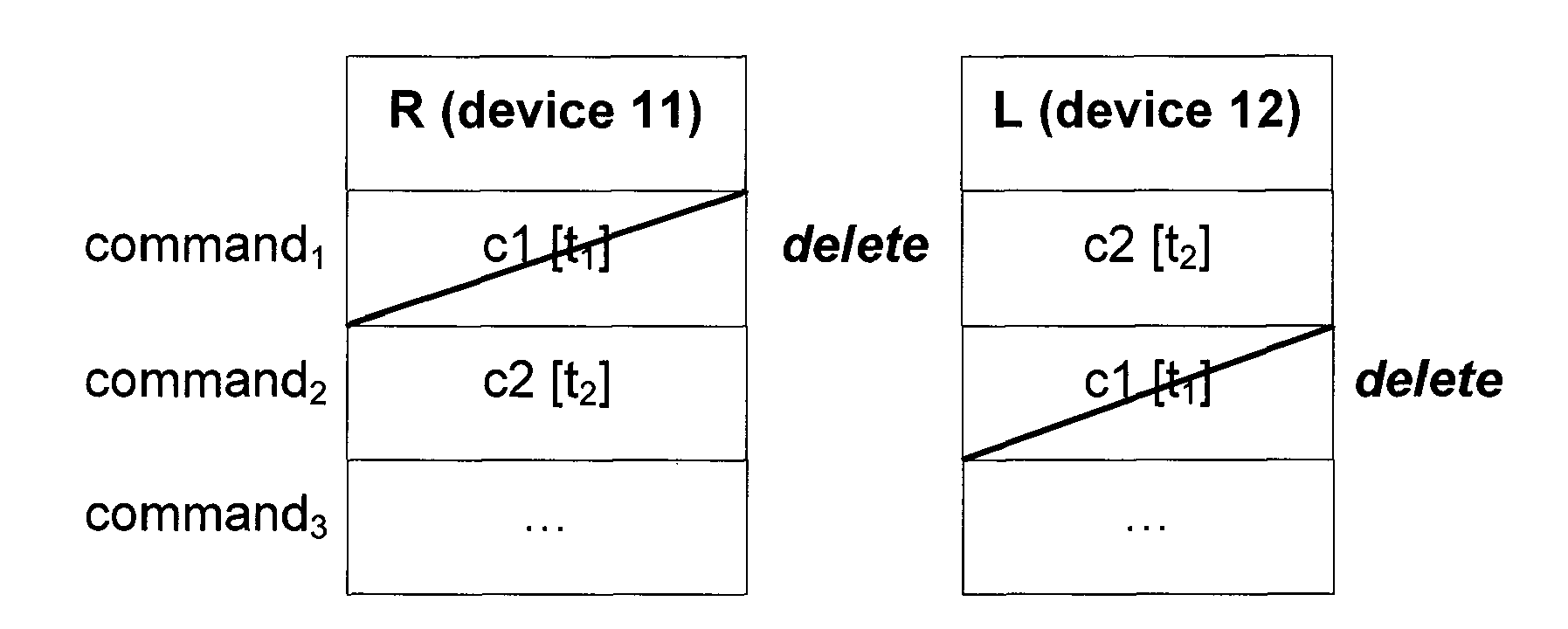
-
Hearing device 11 has two times a command indicating to change to the next hearing program, once from toggling its own program toggle switch (at time t1), and once from toggling at hearing device 12 (at time t2), as received via thelink 5.Hearing device 12 has two times a command indicating to change to the next hearing program, too: once from toggling its own program toggle switch (at time t2), and once from a resending attempt from hearingdevice 11 dating back to the toggling at hearing device 11 (at time t1). Without further processing or intelligence, bothdevices - Therefore, it is advisable to foresee that each
device - Note, that indications of reception of messages are not drawn in the figures.
- Fig. 8 shows an illustration of a case with transfer of a message containing a network time reference indicating the point in time at which a command shall be executed. The hearing system in Fig. 8 comprises two
devices - Frequently, an acoustic acknowledge signal is assigned to actions done to a hearing system. Typical examples of such actions are: changing the volume, changing the hearing program, alarm indicating low battery (battery end-of-life alarm).
- For a binaural hearing system, the user usually expects the acoustic aknowledge signals to appear synchronized on both sides. A network time reference can be used to precisely control the synchronization.
- In Fig. 8, the user toggles the program change switch. This will lead to the generation of a command c1 with a time stamp t1 and another network time reference t2, all combined in a message m1. Like in the examples above, t1 may be the point in time at which the command c1 is generated or at which the message m1 is sent. At the point in time t2, which is deliberately chosen to be later than t1, the acknowledge signal shall be played to the user, whereas the program change shall take place as soon as possible in both
devices devices - In the situation / example of Fig. 8, there can also be two separate messages be produced: one for the (immediate) program change, and one for the acknowledge sound to be played at the later point in time t2.
- Another way to deal with the situation / example of Fig. 8, which also has the same effect as the other two described ways, is that one message is produced, which contains the toggle (program change) command and also the acoustic aknowledge command, thus m1 = (toggle[t1];ackn[t2]). Command stacks of the
devices 
- As has ben shown by means of the various examples and embodiments above, the common network time T not only allows to let program changes, volume changes or acknowledge signals and the like occur simultaneously in each hearing device of a set of binaural hearing devices, but also improves the management of commands and the reliability of the hearing system.
-
- 1
- hearing system
- 11
- device, hearing device
- 110
- clock, internal clock
- 115
- transmitter
- 12
- device, hearing device
- 120
- clock, internal clock
- 125
- receiver
- 13
- device, remote control
- 133
- timepiece, internal timepiece
- 5
- wireless link, communication link
- ci
- command
- L
- left
- mi
- message
- n
- number of network time units that passed since the network time zero point
- r
- (external) reference time base
- R
- right
- ti
- network time reference
- T
- common network time
- Tn
- current network time
- Tn' ,Tn"
- time information
- T0
- network time zero point
- δt
- network time unit
- Δt
- time interval
- www
- internet
Claims (26)
- Method of operating a hearing system (1) comprising at least two devices (11,12,13), said method comprising the step ofa) establishing a common network time (T) among said at least two devices (11,12,13).
- Method according to claim 1, comprising the step ofk) transmitting, by a first (13) of said at least two devices (11,12,13), information on the current network time (Tn).
- Method according to claim 2, comprising the step ofl) receiving, by at least one other (11,12) of said at least two devices (11,12,13), said information on the current network time (Tn).
- Method according to one of the preceding claims, comprising the step ofb) providing said at least two devices (11,12,13) with information on the number (n) of network time units (δt) that passed since a time zero point (T0) of said common network time (T).
- Method according to one of the preceding claims, wherein step a) and/or step b) and/or step k) and/or step l) is carried out via a wireless link (5).
- Method according to one of the preceding claims, comprising the step ofc) providing at least one (11;12) of said at least two devices (11,12,13) with the current network time (Tn) during its boot-time or when it starts to receive messages from another device (13;12;11) of the hearing system (1).
- Method according to one of the preceding claims, comprising the step ofd) providing at least one (11;12) of said at least two devices (11,12,13) with the current network time (Tn) frequently during its operation.
- Method according to one of the preceding claims, comprising the steps ofe) receiving, in at least one (11;12) of said at least two devices (11,12,13), the current network time (Tn); andf) using an internal clock (110;120) of said at least one device (11;12) for generating time information (Tn') at least approximately indicating the current network time (Tn).
- Method according to claim 8, furthermore comprising the step ofg) resynchronizing, after step f), to the common network time (T) upon again receiving the current network time (Tn) in said at least one (11;12) device.
- Method according to one of the preceding claims, comprising the step ofh) generating said common network time (T) within said hearing system (1).
- Method according to one of claims 1 to 9, comprising the step ofi) receiving information on said common network time (T) from a reference time base (r) external to said hearing system (1).
- Method according to one of the preceding claims, comprising the step ofm) transmitting, by a first (13) of said at least two devices (11,12,13), a message (mi) comprising a network time reference (ti).
- Method according to claim 12, comprising the step ofn) receiving, by at least one other (11,12) of said at least two devices (11,12,13), said message (mi).
- Method according to claim 12 or claim 13, wherein said message (mi) comprises, in addition, a command (ci).
- Method according to one of claims 12 to 14, wherein said network time reference (ti) is a time reference (ti) for identifying said message (mi), in particular a time reference (ti), which indicates the point in time of generation of said message (mi) or of said transmitting of said message (mi).
- Method according to one of claims 12 to 14, wherein said network time reference (ti) indicates a point in time, at which said command (ci) is to be executed.
- Method according to one of claims 12 to 16, wherein said transmitting of said message (mi) is carried out in form of broadcasting.
- Hearing system (1) comprising at least two devices (11,12,13) and means for establishing a common network time (T) among said at least two devices (11,12,13).
- System (1) according to claim 18, wherein said means comprise, in at least a first (13) of said at least two devices (11,12,13), a transmitter (115) adapted to transmitting information on the current network time (Tn).
- System (1) according to claim 19, wherein said means comprise, in at least one other (11;12) of said at least two devices (11,12,13), a receiver (125) adapted to receiving said information on the current network time (Tn).
- System (1) according to one of claims 18 to 20, wherein said means comprise a communication link (5) functionally interconnecting said at least two devices (11,12,13), in particular a wireless link (5).
- System (1) according to one of claims 18 to 21, wherein said means comprise a receiver for receiving information on said common network time (T) from a reference time base (r) external to said hearing system (1).
- System (1) according to one of claims 18 to 21, wherein said means comprise, in at least one of said at least two hearing devices (13), a timepiece (133) for generating said common network time (T).
- System (1) according to one of claims 18 to 23, which comprises, in at least one (11;12) of said at least two devices (11,12,13), an internal clock (110;120) for generating time information (Tn') at least approximately indicating the current network time (Tn).
- System (1) according to one of claims 18 to 24, wherein at least one of said at least two devices (11,12,13) is a hearing aid.
- System (1) according to one of claims 18 to 25, which is a binaural hearing system (1).
Priority Applications (3)
| Application Number | Priority Date | Filing Date | Title |
|---|---|---|---|
| DE200660009575 DE602006009575D1 (en) | 2006-05-16 | 2006-05-16 | Hearing system with network time |
| DK06114027.3T DK1715723T4 (en) | 2006-05-16 | 2006-05-16 | Hearing system with network time. |
| EP06114027A EP1715723B2 (en) | 2006-05-16 | 2006-05-16 | Hearing system with network time |
Applications Claiming Priority (1)
| Application Number | Priority Date | Filing Date | Title |
|---|---|---|---|
| EP06114027A EP1715723B2 (en) | 2006-05-16 | 2006-05-16 | Hearing system with network time |
Publications (4)
| Publication Number | Publication Date |
|---|---|
| EP1715723A2 true EP1715723A2 (en) | 2006-10-25 |
| EP1715723A3 EP1715723A3 (en) | 2006-12-06 |
| EP1715723B1 EP1715723B1 (en) | 2009-10-07 |
| EP1715723B2 EP1715723B2 (en) | 2012-12-05 |
Family
ID=36922076
Family Applications (1)
| Application Number | Title | Priority Date | Filing Date |
|---|---|---|---|
| EP06114027A Active EP1715723B2 (en) | 2006-05-16 | 2006-05-16 | Hearing system with network time |
Country Status (3)
| Country | Link |
|---|---|
| EP (1) | EP1715723B2 (en) |
| DE (1) | DE602006009575D1 (en) |
| DK (1) | DK1715723T4 (en) |
Cited By (10)
| Publication number | Priority date | Publication date | Assignee | Title |
|---|---|---|---|---|
| EP2012509A1 (en) | 2007-07-02 | 2009-01-07 | Siemens Medical Instruments Pte. Ltd. | Multicomponent hearing aid system and a method for its operation |
| EP2073571A2 (en) * | 2007-07-06 | 2009-06-24 | Cochlear Limited | Wireless communications between devices of a hearing prosthesis |
| WO2009080108A1 (en) * | 2007-12-20 | 2009-07-02 | Phonak Ag | Hearing system with joint task scheduling |
| EP1750482A3 (en) * | 2005-08-04 | 2010-08-04 | Siemens Audiologische Technik GmbH | Method for the synchronisation of signal tones and corresponding hearing device |
| US8190189B2 (en) * | 2009-01-21 | 2012-05-29 | Oticon A/S | Power management in low power wireless link |
| US8213652B2 (en) | 2007-07-02 | 2012-07-03 | Siemens Medical Instruments Pte. Ltd. | Multi-component hearing aid system and a method for its operation |
| JP2015173437A (en) * | 2014-02-24 | 2015-10-01 | ジーエヌ リザウンド エー/エスGn Resound A/S | Resource Manager |
| EP3086575A1 (en) * | 2015-04-24 | 2016-10-26 | Sivantos Pte. Ltd. | Method of synchronizing the reproduction of a digital signal sent from a transmitter to a plurality of mobile audio end devices |
| US10244333B2 (en) * | 2016-06-06 | 2019-03-26 | Starkey Laboratories, Inc. | Method and apparatus for improving speech intelligibility in hearing devices using remote microphone |
| EP3883263A1 (en) * | 2020-03-16 | 2021-09-22 | Sonova AG | Hearing device |
Citations (3)
| Publication number | Priority date | Publication date | Assignee | Title |
|---|---|---|---|---|
| DE10048341C1 (en) | 2000-09-29 | 2002-04-18 | Siemens Audiologische Technik | Operating hearing aid involves receiving signal from external transmitter in hearing aid in close proximity to transmitter, associating received signal to hearing situation adapting to situation |
| US20020131613A1 (en) | 2001-03-13 | 2002-09-19 | Andreas Jakob | Method for establishing a binaural communication link and binaural hearing devices |
| EP1657958A1 (en) | 2005-06-27 | 2006-05-17 | Phonak Ag | Communication system and hearing device |
Family Cites Families (8)
| Publication number | Priority date | Publication date | Assignee | Title |
|---|---|---|---|---|
| EP1316240B1 (en) * | 2000-07-14 | 2005-11-09 | GN ReSound as | A synchronised binaural hearing system |
| GB2387932B (en) † | 2002-04-26 | 2005-06-22 | Motorola Inc | Apparatus and method for scheduling tasks in a communications network |
| JP3900522B2 (en) † | 2002-08-29 | 2007-04-04 | ヤマハ株式会社 | Command synchronization establishment system and method |
| DE10304648B3 (en) * | 2003-02-05 | 2004-08-19 | Siemens Audiologische Technik Gmbh | Device and method for communicating hearing aids |
| US20040190737A1 (en) * | 2003-03-25 | 2004-09-30 | Volker Kuhnel | Method for recording information in a hearing device as well as a hearing device |
| US7778432B2 (en) * | 2003-06-06 | 2010-08-17 | Gn Resound A/S | Hearing aid wireless network |
| GB2406019B (en) † | 2003-09-11 | 2007-06-13 | Toumaz Technology Ltd | Digital transmission system |
| DE102005036851B3 (en) † | 2005-08-04 | 2006-11-23 | Siemens Audiologische Technik Gmbh | Synchronizing signal tones output by hearing aids for binaural hearing aid supply involves sending control signal with count value at which signal tone is to be output from first to second hearing aid, outputting tones when values reached |
-
2006
- 2006-05-16 DE DE200660009575 patent/DE602006009575D1/en active Active
- 2006-05-16 EP EP06114027A patent/EP1715723B2/en active Active
- 2006-05-16 DK DK06114027.3T patent/DK1715723T4/en active
Patent Citations (3)
| Publication number | Priority date | Publication date | Assignee | Title |
|---|---|---|---|---|
| DE10048341C1 (en) | 2000-09-29 | 2002-04-18 | Siemens Audiologische Technik | Operating hearing aid involves receiving signal from external transmitter in hearing aid in close proximity to transmitter, associating received signal to hearing situation adapting to situation |
| US20020131613A1 (en) | 2001-03-13 | 2002-09-19 | Andreas Jakob | Method for establishing a binaural communication link and binaural hearing devices |
| EP1657958A1 (en) | 2005-06-27 | 2006-05-17 | Phonak Ag | Communication system and hearing device |
Cited By (15)
| Publication number | Priority date | Publication date | Assignee | Title |
|---|---|---|---|---|
| US7844062B2 (en) | 2005-08-04 | 2010-11-30 | Siemens Audiologische Technik Gmbh | Method for the synchronization of signal tones and corresponding hearing aids |
| EP1750482A3 (en) * | 2005-08-04 | 2010-08-04 | Siemens Audiologische Technik GmbH | Method for the synchronisation of signal tones and corresponding hearing device |
| EP2012509A1 (en) | 2007-07-02 | 2009-01-07 | Siemens Medical Instruments Pte. Ltd. | Multicomponent hearing aid system and a method for its operation |
| US8213652B2 (en) | 2007-07-02 | 2012-07-03 | Siemens Medical Instruments Pte. Ltd. | Multi-component hearing aid system and a method for its operation |
| EP2688316A1 (en) * | 2007-07-06 | 2014-01-22 | Cochlear Limited | Wireless communication for a hearing aid system |
| EP2073571A3 (en) * | 2007-07-06 | 2012-05-23 | Cochlear Limited | Wireless communications between devices of a hearing prosthesis |
| EP2073571A2 (en) * | 2007-07-06 | 2009-06-24 | Cochlear Limited | Wireless communications between devices of a hearing prosthesis |
| WO2009080108A1 (en) * | 2007-12-20 | 2009-07-02 | Phonak Ag | Hearing system with joint task scheduling |
| US8477975B2 (en) | 2007-12-20 | 2013-07-02 | Phonak Ag | Hearing system with joint task scheduling |
| US8190189B2 (en) * | 2009-01-21 | 2012-05-29 | Oticon A/S | Power management in low power wireless link |
| JP2015173437A (en) * | 2014-02-24 | 2015-10-01 | ジーエヌ リザウンド エー/エスGn Resound A/S | Resource Manager |
| EP3086575A1 (en) * | 2015-04-24 | 2016-10-26 | Sivantos Pte. Ltd. | Method of synchronizing the reproduction of a digital signal sent from a transmitter to a plurality of mobile audio end devices |
| US9860654B2 (en) | 2015-04-24 | 2018-01-02 | Sivantos Pte. Ltd. | Method for synchronizing the reproduction of a digital signal sent by a transmitter to a plurality of mobile audio terminals |
| US10244333B2 (en) * | 2016-06-06 | 2019-03-26 | Starkey Laboratories, Inc. | Method and apparatus for improving speech intelligibility in hearing devices using remote microphone |
| EP3883263A1 (en) * | 2020-03-16 | 2021-09-22 | Sonova AG | Hearing device |
Also Published As
| Publication number | Publication date |
|---|---|
| DK1715723T3 (en) | 2009-12-14 |
| EP1715723A3 (en) | 2006-12-06 |
| EP1715723B2 (en) | 2012-12-05 |
| DK1715723T4 (en) | 2013-03-18 |
| EP1715723B1 (en) | 2009-10-07 |
| DE602006009575D1 (en) | 2009-11-19 |
Similar Documents
| Publication | Publication Date | Title |
|---|---|---|
| EP1715723B1 (en) | Hearing system with network time | |
| US8588443B2 (en) | Hearing system with network time | |
| AU774579B2 (en) | Binaural synchronisation | |
| US11689852B2 (en) | Audio rendering system | |
| EP2456234B1 (en) | Wireless binaural hearing system | |
| EP2117180B1 (en) | A short range, uni-directional wireless link | |
| US11784678B2 (en) | Audio stream detection | |
| EP2439960B1 (en) | Wireless binaural hearing system | |
| JPH03505960A (en) | Mobile handset unit and telephone communication system | |
| EP3008923B1 (en) | A method of operating a binaural hearing aid system and a binaural hearing aid system | |
| EP1860914B1 (en) | Hearing assistance system and method of operating the same | |
| JP5925209B2 (en) | Hearing apparatus and method for compensating for frequency difference between transmitter and receiver | |
| EP1885072B1 (en) | Method and system for visual indication of the function of wireless receivers and a wireless receiver. | |
| US8121298B2 (en) | Hearing aid |
Legal Events
| Date | Code | Title | Description |
|---|---|---|---|
| PUAI | Public reference made under article 153(3) epc to a published international application that has entered the european phase |
Free format text: ORIGINAL CODE: 0009012 |
|
| AK | Designated contracting states |
Kind code of ref document: A2 Designated state(s): AT BE BG CH CY CZ DE DK EE ES FI FR GB GR HU IE IS IT LI LT LU LV MC NL PL PT RO SE SI SK TR |
|
| AX | Request for extension of the european patent |
Extension state: AL BA HR MK YU |
|
| PUAL | Search report despatched |
Free format text: ORIGINAL CODE: 0009013 |
|
| AK | Designated contracting states |
Kind code of ref document: A3 Designated state(s): AT BE BG CH CY CZ DE DK EE ES FI FR GB GR HU IE IS IT LI LT LU LV MC NL PL PT RO SE SI SK TR |
|
| AX | Request for extension of the european patent |
Extension state: AL BA HR MK YU |
|
| 17P | Request for examination filed |
Effective date: 20070526 |
|
| 17Q | First examination report despatched |
Effective date: 20070625 |
|
| AKX | Designation fees paid |
Designated state(s): CH DE DK LI |
|
| GRAP | Despatch of communication of intention to grant a patent |
Free format text: ORIGINAL CODE: EPIDOSNIGR1 |
|
| GRAS | Grant fee paid |
Free format text: ORIGINAL CODE: EPIDOSNIGR3 |
|
| GRAA | (expected) grant |
Free format text: ORIGINAL CODE: 0009210 |
|
| AK | Designated contracting states |
Kind code of ref document: B1 Designated state(s): CH DE DK LI |
|
| REG | Reference to a national code |
Ref country code: CH Ref legal event code: EP |
|
| REG | Reference to a national code |
Ref country code: CH Ref legal event code: NV Representative=s name: TROESCH SCHEIDEGGER WERNER AG |
|
| REF | Corresponds to: |
Ref document number: 602006009575 Country of ref document: DE Date of ref document: 20091119 Kind code of ref document: P |
|
| REG | Reference to a national code |
Ref country code: DK Ref legal event code: T3 |
|
| PLBI | Opposition filed |
Free format text: ORIGINAL CODE: 0009260 |
|
| PLAX | Notice of opposition and request to file observation + time limit sent |
Free format text: ORIGINAL CODE: EPIDOSNOBS2 |
|
| 26 | Opposition filed |
Opponent name: SIEMENS AUDIOLOGISCHE TECHNIK GMBH Effective date: 20100707 |
|
| PLBB | Reply of patent proprietor to notice(s) of opposition received |
Free format text: ORIGINAL CODE: EPIDOSNOBS3 |
|
| PLAB | Opposition data, opponent's data or that of the opponent's representative modified |
Free format text: ORIGINAL CODE: 0009299OPPO |
|
| R26 | Opposition filed (corrected) |
Opponent name: SIEMENS AUDIOLOGISCHE TECHNIK GMBH Effective date: 20100707 |
|
| PUAH | Patent maintained in amended form |
Free format text: ORIGINAL CODE: 0009272 |
|
| STAA | Information on the status of an ep patent application or granted ep patent |
Free format text: STATUS: PATENT MAINTAINED AS AMENDED |
|
| 27A | Patent maintained in amended form |
Effective date: 20121205 |
|
| AK | Designated contracting states |
Kind code of ref document: B2 Designated state(s): CH DE DK LI |
|
| REG | Reference to a national code |
Ref country code: CH Ref legal event code: AELC |
|
| REG | Reference to a national code |
Ref country code: DE Ref legal event code: R102 Ref document number: 602006009575 Country of ref document: DE Effective date: 20121205 |
|
| REG | Reference to a national code |
Ref country code: DK Ref legal event code: T4 |
|
| REG | Reference to a national code |
Ref country code: DE Ref legal event code: R084 Ref document number: 602006009575 Country of ref document: DE |
|
| PGFP | Annual fee paid to national office [announced via postgrant information from national office to epo] |
Ref country code: DK Payment date: 20230530 Year of fee payment: 18 Ref country code: DE Payment date: 20230530 Year of fee payment: 18 Ref country code: CH Payment date: 20230610 Year of fee payment: 18 |