EP2687953A2 - Mouse device - Google Patents
Mouse device Download PDFInfo
- Publication number
- EP2687953A2 EP2687953A2 EP13168893.9A EP13168893A EP2687953A2 EP 2687953 A2 EP2687953 A2 EP 2687953A2 EP 13168893 A EP13168893 A EP 13168893A EP 2687953 A2 EP2687953 A2 EP 2687953A2
- Authority
- EP
- European Patent Office
- Prior art keywords
- main body
- back cover
- mouse device
- disposed
- pads
- Prior art date
- Legal status (The legal status is an assumption and is not a legal conclusion. Google has not performed a legal analysis and makes no representation as to the accuracy of the status listed.)
- Withdrawn
Links
Images




Classifications
-
- G—PHYSICS
- G06—COMPUTING OR CALCULATING; COUNTING
- G06F—ELECTRIC DIGITAL DATA PROCESSING
- G06F3/00—Input arrangements for transferring data to be processed into a form capable of being handled by the computer; Output arrangements for transferring data from processing unit to output unit, e.g. interface arrangements
- G06F3/01—Input arrangements or combined input and output arrangements for interaction between user and computer
- G06F3/03—Arrangements for converting the position or the displacement of a member into a coded form
- G06F3/033—Pointing devices displaced or positioned by the user, e.g. mice, trackballs, pens or joysticks; Accessories therefor
-
- G—PHYSICS
- G06—COMPUTING OR CALCULATING; COUNTING
- G06F—ELECTRIC DIGITAL DATA PROCESSING
- G06F3/00—Input arrangements for transferring data to be processed into a form capable of being handled by the computer; Output arrangements for transferring data from processing unit to output unit, e.g. interface arrangements
- G06F3/01—Input arrangements or combined input and output arrangements for interaction between user and computer
- G06F3/03—Arrangements for converting the position or the displacement of a member into a coded form
- G06F3/033—Pointing devices displaced or positioned by the user, e.g. mice, trackballs, pens or joysticks; Accessories therefor
- G06F3/0354—Pointing devices displaced or positioned by the user, e.g. mice, trackballs, pens or joysticks; Accessories therefor with detection of two-dimensional [2D] relative movements between the device, or an operating part thereof, and a plane or surface, e.g. 2D mice, trackballs, pens or pucks
- G06F3/03543—Mice or pucks
Definitions
- a mouse device comprising a shell body, at least one replaceable cover, and a plurality of pads.
- the replaceable cover is disposed at the bottom of the shell body, and the pads are respectively disposed at the both sides of the replaceable cover.
- the pads on the both sides can be used by flipping the replaceable cover over.
- the pads on one side of the replaceable cover wear out, by flipping the replaceable cover over, the pads on the other side thereof can be utilized instead.
- the user doesn't have to discard the entire mouse device simply because of the worn-out pads, thus prolonging the lifetime of the mouse device.
- such conventional mouse device should be configured symmetrically on both sides and the material of the pads is preferably the same. Otherwise, it is apparent that some problems will occur when flipping the replaceable cover over.
- Fig. 4 is a sectional view of the first embodiment of the present invention.
- Fig.7 is a partial breakdown diagram of a second embodiment of the present invention.
- the mouse device 100 includes a main body 110, a circuit assembly 120 and a back cover 130.
- the main body 110 is composed of an upper shell body 111 and a lower shell body 112, thereby forming an inner accommodating space.
- a plurality of buttons 118 and a wheel 117 are provided on a top surface of the upper shell body 111, and a bottom of the lower shell body 112 has a plurality of slots 113, two guiding grooves 114 and a sliding track 115.
- the slots 113 are disposed at a front, rear, left and right of the bottom of the lower shell body 112 respectively.
- the two guiding grooves 114 are disposed symmetrically at the front of the bottom of the lower shell body 112.
- the sliding track 115 is disposed at the rear of the bottom of the lower shell body 112 and has a U-shape.
- the hooks 143/153 are disposed at a front, rear, left and right of the first back cover 140 or the second back cover 150 and located corresponding to the slots 113 on the bottom of the lower shell body 112 respectively, while the two positioning components 144 or 154 are disposed at the first sides 141 or 151 of the first back cover 140 or the second back cover 150 and located corresponding to a plurality of guiding grooves 114 on the bottom of the lower shell body 112 respectively.
Landscapes
- Engineering & Computer Science (AREA)
- General Engineering & Computer Science (AREA)
- Theoretical Computer Science (AREA)
- Human Computer Interaction (AREA)
- Physics & Mathematics (AREA)
- General Physics & Mathematics (AREA)
- Position Input By Displaying (AREA)
Abstract
Description
- The present invention relates to a mouse device, especially to a mouse device comprising a replaceable back cover.
- As technology moves on, the prevailing of computers has brought many conveniences to common life by audio/video streams, e-mails, computer-aided art designing and game entertainments. As the increasing requirement on computer facilities, new technology is kept being developed for enhancing the functionality of the computer itself together with the peripherals especially human-machine interface (HMI) input devices. Among others, the mouse device is most frequently used.
- Conventionally, instructions are executed or the window is scrolled in an operating system of a computer by clicking buttons or scrolling a wheel on the mouse device. However, for the most part, whether the cursor in a window can move smoothly on the screen depends on the contact between the pad(s) on the bottom of the mouse and a working surface like a desk surface or a mouse pad. Needless to say, the material of the working surface will influence the movement of the mouse device.
- Furthermore, after long term use of the mouse device, wear of pads due to friction is inevitable and consequently the mouse device cannot be operated smoothly. For example, the sensitivity and operability of the mouse device may degrade undesirably so that it should be discarded finally. As a result, there is a need for a mouse device in which the pad(s) on the bottom thereof can be replaced easily.
- To solve the above problem, a mouse device has been proposed comprising a shell body, at least one replaceable cover, and a plurality of pads. The replaceable cover is disposed at the bottom of the shell body, and the pads are respectively disposed at the both sides of the replaceable cover. The pads on the both sides can be used by flipping the replaceable cover over. When the pads on one side of the replaceable cover wear out, by flipping the replaceable cover over, the pads on the other side thereof can be utilized instead. The user doesn't have to discard the entire mouse device simply because of the worn-out pads, thus prolonging the lifetime of the mouse device. However, such conventional mouse device should be configured symmetrically on both sides and the material of the pads is preferably the same. Otherwise, it is apparent that some problems will occur when flipping the replaceable cover over.
- As the above conventional mouse device requires the same material for the pads on both sides, it is not suitable for those who have to use the pads of different material under different situations. Therefore, in the marketplace, a mouse device is needful in which the pads underlying the bottom thereof can be easily and conveniently replaced with those of different material. It is believed that the inventive and cost-effective mouse device will provide more convenience and operational flexibility than the conventional one.
- In view of this, the present invention solves the above problems by providing a mouse device in which the pads can be replaced easily either when worn out or for different material.
- In one embodiment, a mouse device used on a surface comprises a main body, a circuit assembly and a back cover. The main body comprises an inner accommodating space to contain the circuit assembly executing default functions of the mouse device. A bottom of the main body comprises at least one slot. One side of the back cover comprises at least one hook located corresponding to the slot, and the other side of the back cover comprises a plurality of pads by which the back cover contacts with the surface. The back cover is detachably disposed at the bottom of the main body and buckled to the slot by the hook so that the back cover is firmly combined with the main body.
- In another embodiment, a mouse device used on a surface comprises a main body, a circuit assembly, a first back cover and a second back cover. The main body comprises an inner accommodating space to contain the circuit assembly executing default functions of the mouse device. A bottom of the main body comprises at least one slot and a plurality of concaves. One side of the two back covers comprises a plurality of hooks located corresponding to the slot, and the other side of the two back covers comprises a plurality of pads by which the back cover contacts with the surface. The material of the pads of the first back cover is different from that of the pads of the second back cover. One of the two back covers is selected to be detachably disposed at the bottom of the main body and buckled to the slot by the hooks so that the back cover is firmly combined with the main body. In particular, the pads of the first back cover are projectively disposed at the side of the first back cover and are located within the concaves when the first back cover is selected to be disposed at the bottom of the main body.
- The present invention is advantageous basically because the back cover of the mouse device is designed to be detachably disposed at the main body of the mouse device. Thus, the pads can be replaced easily whenever desired, and the material of the pads is not confined to be identical with the original one. The entire mouse device therefore has a prolonged lifetime and brings about more convenience and flexibility for the user.
- It should be emphasized that by taking advantage of the concave structure of the main body, the distance between the main body and the working surface of the mouse device can be kept constant in spite of varied thickness of the pads. In this way, the mouse device can accurately execute operation and avoid false operation effectively.
- These and other objectives of the present invention will no doubt become obvious to those of ordinary skill in the art after reading the following detailed description of the preferred embodiments that is illustrated in the various figures and drawings.
-
Fig. 1 is a partial breakdown diagram of a first embodiment of the present invention. -
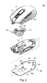
Fig. 2 is a partial breakdown diagram of the first embodiment of the present invention in another viewpoint. -
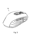
Fig. 3 is a three dimensional view of the first embodiment of the present invention. -
Fig. 4 is a sectional view of the first embodiment of the present invention. -
Fig.5a to Fig.5e are sectional side views of the main body and the back cover of the first embodiment of the present invention. -
Fig.6 is a sectional side view of the mouse device of the first embodiment of the present invention wherein the mouse device is under operation. -
Fig.7 is a partial breakdown diagram of a second embodiment of the present invention. -
Fig.8 is a partial breakdown diagram of the second embodiment of the present invention. -
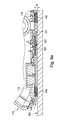
Fig.9a is a sectional side view of the main body and the first back cover of the second embodiment of the present invention. -
Fig.9b is a sectional side view of the main body and the second back cover of the second embodiment of the present invention. - It is noted that in the following embodiments a gaming mouse is used as an exemplary interpretation of a
mouse device 100 without any intention to limit the scope of the present invention. Those skilled in the art may modify the appearance and the function of themouse device 100 according to user requirements. -
Figs. 1 and2 are partial breakdown diagrams of themouse device 100 of the first embodiment. Themouse device 100 is operated on asurface 160 like a desk surface or mouse pad of some kind of material for correspondingly controlling a cursor action in an operating system of a computer device (not shown) and executing default functions. - In this embodiment, the
mouse device 100 includes amain body 110, acircuit assembly 120 and aback cover 130. Themain body 110 is composed of anupper shell body 111 and alower shell body 112, thereby forming an inner accommodating space. A plurality ofbuttons 118 and awheel 117 are provided on a top surface of theupper shell body 111, and a bottom of thelower shell body 112 has a plurality ofslots 113, two guidinggrooves 114 and asliding track 115. - In more detail, the
slots 113 are disposed at a front, rear, left and right of the bottom of thelower shell body 112 respectively. The two guidinggrooves 114 are disposed symmetrically at the front of the bottom of thelower shell body 112. The slidingtrack 115 is disposed at the rear of the bottom of thelower shell body 112 and has a U-shape. - The
circuit assembly 120 is similar to the electrical component of a conventional mouse device for executing default functions such as moving the cursor, clicking to invoke programs, scrolling pages and bringing up menus. So the details related to the functions are not described herein for avoiding unnecessary confusion. However, the electrical components involved in the present invention will be explicitly interpreted in the following paragraphs. - The
circuit assembly 120 includes acircuit board 121, alight emitting device 122 and anoptical sensor 123. Thelight emitting device 122 and theoptical sensor 123 are electrically disposed on thecircuit board 121 that is screwed to thelower shell body 112 of themain body 110 and located in the accommodating space formed by theupper shell body 111 and thelower shell body 112. The bottom of thelower shell body 112 of themain body 110 has an opening exposing theoptical sensor 123 and thelight emitting device 122 from the bottom of thelower shell body 112. Thelight emitting device 122 emits a light toward asurface 160, and theoptical sensor 123 receives and detects the light reflected from thesurface 160. Thebuttons 118 and thewheel 117 are electrically connected to thecircuit assembly 120 as input devices. Thelight emitting device 122 may be but not limited to a light-emitting diode (LED) or a bulb. - The
back cover 130 is detachably disposed on the bottom of thelower shell body 112 of themain body 110 and has afirst side 131 and asecond side 132 opposed to each other. Thefirst side 131 is provided with a plurality ofhooks 133 and twopositioning components 134. Thehooks 133 are disposed at a front, rear, left and right of theback cover 130 and located corresponding to theslots 113 on the bottom of thelower shell body 112 respectively, while thepositioning components 134 respectively correspond to the guidinggrooves 114 on the bottom of thelower shell body 112. - Besides, the
second side 132 of theback cover 130 has a plurality ofpads 136 that can be made of Teflon, ceramics or glass. Thepads 136 are evenly arranged on thesecond side 132 of theback cover 130 by for example gluing, wedging or screwing. It is to be noted that the material of thepads 136 is not limited to those mentioned above, and thepads 136 may be disposed in desired positions on theback cover 130 by using other method than what are disclosed here. -
Figs. 3 to 5e are schematic illustrations of the mouse device of the first embodiment. When combining theback cover 130 with themain body 110 in assembling themouse device 100, thefirst side 131 of theback cover 130 faces the bottom of themain body 110, and an outer edge of theback cover 130 is slid into the slidingtrack 115 provided on the bottom of themain body 110 to secure theback cover 130 to themain body 110. Also, thepositioning components 134 on thefirst side 131 of theback cover 130 are slid into the guidinggrooves 114 on the bottom of themain body 110 in order to serve as a guide for theback cover 130 to facilitate the positioning. Consequently, thehooks 133 are respectively buckled to theslots 113 on the bottom of themain body 110, so that theback cover 130 is firmly combined with themain body 110. -
Fig.6 illustrates a sectional side view of a light path of themouse device 100 in use according to the first embodiment. Theback cover 130 includes anopening 135 penetrating thefirst side 131 and thesecond side 132 and corresponding to an aperture at the bottom of thelower shell body 112. In this way, light emitted from thelight emitting device 122 of thecircuit assembly 120 passes through theopening 135 of theback cover 130, projects onto thesurface 160, and reflects from thesurface 160. Then, the reflected light passing through theopening 135 again in the reverse direction is received by theoptical sensor 123 of thecircuit board 121. Themouse device 100 can be moved on thesurface 160 with thepads 136 on theback cover 130 contacting the working surface directly. Theoptical sensor 123 constantly receives the dynamic signals from the light and the cursor on the screen moves correspondingly. Thebuttons 118 and thewheel 117 on the top of themain body 110 are configured to select or interact with an element of a graphical user interface, as is well-known to one of ordinary skill. - To sum up, in the embodiment, the
mouse device 100 takes advantage of the hooks and the slots to achieve an easy replacement of theback cover 130. -
Figs. 7 to 9b are partial breakdown diagrams and sectional side views of a second embodiment of the present invention. The structure of amouse device 100 of the second embodiment is basically similar to that of the first embodiment with only some differences that will be addressed later. - The
mouse device 100 includes amain body 110, acircuit assembly 120, afirst back cover 140 and asecond back cover 150. Themain body 110 has an inner accommodating space to contain thecircuit assembly 120 executing default functions of themouse device 100. A bottom of themain body 110 has a plurality ofslots 113 and a plurality ofconcaves 116. One of the first and the second back covers 140 and 150 is selected arbitrarily to be detachably disposed at the bottom of alower shell body 112 of themain body 110. The two back covers 140 and 150 that are similar in structure in this embodiment respectively includes afirst side 141/151 and asecond side 142/152 opposed to each other. And thefirst side 141/151 is provided with a plurality ofhooks 143/153 and twopositioning components 144/154. - In more detail, the
hooks 143/153 are disposed at a front, rear, left and right of thefirst back cover 140 or thesecond back cover 150 and located corresponding to theslots 113 on the bottom of thelower shell body 112 respectively, while the twopositioning components first sides first back cover 140 or thesecond back cover 150 and located corresponding to a plurality of guidinggrooves 114 on the bottom of thelower shell body 112 respectively. - Besides, the
second side first back cover 140 or thesecond back cover 150 has a plurality ofpads pads 146 of thefirst back cover 140 can be made of ceramics, and thepads 156 of thesecond back cover 150 can be made of Teflon. Thepads second side pads pads - The difference between the two back covers 140 and 150 is that the
pads 146 of thefirst back cover 140 are projectively disposed at thefirst side 141 of thefirst back cover 140, while thepads 156 of thesecond back cover 150 are not projectively disposed at thefirst side 151 of thesecond back cover 150. - When combining one of the two back covers 140 and 150 with the
main body 110 in assembling themouse device 100, thefirst side first back cover 140 or thesecond back cover 150 faces the bottom of themain body 110, and an outer edge of theback cover track 115 provided on the bottom of themain body 110 to secure theback cover main body 110. Also, thepositioning components first side grooves 114 on the bottom of themain body 110 in order to serve as a guide for theback cover hooks slot 113 on the bottom of themain body 110, so that theback cover main body 110. (Please also refer toFig.3 to Fig.5e of the first embodiment.) -
Fig.9a is a sectional side view of the main body and the first back cover of the second embodiment, andFig.9b is a sectional side view of the main body and the second back cover of the second embodiment. Since thepads 146 of thefirst back cover 140 are made of ceramics and are somewhat thick due to the limitation on molding technique, thepads 146 are projectively disposed at thefirst side 141 of thefirst back cover 140. As a result, when thefirst back cover 140 is selected to be disposed at the bottom of themain body 110, thepads 146 projectively disposed at thefirst side 141 are located within theconcaves 116 respectively. Thus, thefirst side 141 can be attached to the bottom of themain body 110 without any space therebetween and a gap of D is disposed between themain body 110 where thefirst back cover 140 is provided and asurface 160 during operation. Alternatively, when thesecond back cover 150 is selected to be disposed at the bottom of themain body 110, thefirst side 151 can also be attached to the bottom of themain body 110 without any space therebetween. Since thepads 156 will not project from thefirst side 151 of thesecond back cover 150, they won't impede the assembly of thesecond back cover 150. So the same gap of D exists between themain body 110 where thesecond cover 150 is disposed and thesurface 160 during operation. - Besides, each of the two back covers 140 and 150 includes an
opening first side second side lower shell body 112. In this way, light emitted from thelight emitting device 122 on acircuit board 121 of thecircuit assembly 120 may project onto and reflect from thesurface 160 through theopening back cover opening optical sensor 123 on thecircuit board 121. - As a result, although the thickness of the
pads main body 110 disposed with either of the back covers 140 and 150 and asurface 160 can be kept constant during operation due to the concaves located on the bottom of themain body 110. - As the
pads 146 of thefirst back cover 140 made of ceramic material and thepads 156 of thesecond back cover 150 made of Teflon may be different in thickness, theconcaves 116 at the bottom of themain body 110 are designed and adjusted such that the gap of D is maintained between themain body 110 and thesurface 160 no matterback cover main body 110. Therefore, theoptical sensor 123 and themouse device 100 can work smoothly in spite of the different back covers. - To sum up, in the embodiment, the material of the pads of the back cover may be varied if required. In addition, the structure of the concaves is employed for the
mouse device 100 to include the back covers with the pads of different material as desired without changing the gap distance between the main body and the working surface. - In the aforementioned embodiments, it is clearly described that the present invention solves the existing problems by providing the mouse device in which the pads can be replaced easily either when worn out or for different material.
- The present invention is advantageous because the back cover of the mouse device is designed to be detachably disposed at the main body of the mouse device. Thus, the pads can be replaced easily whenever desired, and the material of the pads is not confined to be identical with the original one. The entire mouse device therefore has a prolonged lifetime and brings about more convenience and flexibility for the user.
- The aforementioned descriptions represent merely the preferred embodiment of the present invention, without any intention to limit the scope of the present invention thereto. Various equivalent changes, alterations, or modifications based on the claims of the present invention are all consequently viewed as being embraced by the scope of the present invention.
Claims (14)
- A mouse device (100) used on a surface (160), comprising:a main body (110) comprising a bottom and at least one slot (113) disposed at the bottom;a circuit assembly (120) disposed within the main body (110) and executing a default function of the mouse device (100); anda back cover (130) comprising a first side (131), a second side (132), at least one hook (133) at the first side (131), and a plurality of pads (136) at the second side (132), the back cover (130) contacting with the surface (160) via the pads (136), being disposed detachably at the bottom of the main body (110) and buckled to the slot (113) by the hook (133).
- The mouse device (100) of claim 1, wherein the circuit assembly (120) comprises a circuit board (121), a light emitting device (122) and an optical sensor (123), in which the light emitting device (122) and the optical sensor (123) are electrically disposed on the circuit board (121), the back cover (130) includes an opening (135) corresponding to the light emitting device (122) and the optical sensor (123), the light emitting device (122) emits a light through the opening (135) to the surface (160), and the optical sensor (123) receives the light reflected from the surface (160) through the opening (135).
- The mouse device (100) of claim 1, wherein the main body (110) comprises an upper shell body (111) and a lower shell body (112), both of which are assembled to form an accommodating space to contain the circuit assembly (120), and the slot (113) is located on the bottom of the lower shell body (112).
- The mouse device (100) of claim 1, wherein the bottom of the main body (110) further comprises a guiding groove (114) at a front end of the main body (110), and the back cover (130) comprises a positioning component (134) corresponding to the guiding groove (114) for sliding into the guiding groove (114) when the back cover (130) is disposed at the bottom of the main body (110).
- The mouse device (100) of claim 1, wherein the bottom of the main body (110) comprises the slots (113) at a front, rear, left and right of the main body (110) respectively, the back cover (130) comprises a plurality of hooks (133) corresponding to and buckled to the slots (113) respectively when disposed at the bottom of the main body (110).
- The mouse device (100) of claim 5, wherein the bottom of the main body (110) further comprises a sliding track (115) for an outer edge of the back cover (130) to be inserted thereinto so that the hooks (133) are buckled to the slots (113) respectively.
- The mouse device (100) of claim 1, wherein the pads (136) are made of Teflon or ceramics.
- A mouse device (100) used on a surface (160), comprising:a main body (110) comprising a bottom and at least one slot (113) and a plurality of concaves (116) disposed at the bottom;a circuit assembly (120) disposed within the main body (110) and executing a default function of the mouse device (100); anda first back cover (140) and a second back cover (150), each of which has at least one hook (143, 153) at a first side (141, 151) thereof and a plurality of pads (146, 156) at a second side (142, 152) thereof and contacts the surface (160) via the pads (146, 156), material of the pads (146) of the first back cover (140) being different from that of the second back cover (150), wherein one of the first and the second back covers (140, 150) is selected arbitrarily to be detachably disposed at the bottom of the main body (110), and the back cover (140, 150) that is selected to be disposed and the slot (113) of the main body (110) are buckled by the hook (143, 153), wherein the pads (146) of the first back cover (140) are projectively disposed at the first side (141) of the first back cover (140), and when the first back cover (140) is selected to be disposed at the bottom of the main body (110), the pads (146) projectively disposed at the first side (141) of the first back cover (140) are located within the concaves (116).
- The mouse device (100) of claim 8, wherein the circuit assembly (120) comprises a circuit board (121), a light emitting device (122) and an optical sensor (123), in which the light emitting device (122) and the optical sensor (123) are electrically disposed on the circuit board (121), each of the two back covers (140, 150) comprises an opening (145, 155) corresponding to the light emitting device (122) and the optical sensor (123), the light emitting device (122) emits a light through the opening (145, 155) to the surface (160), and the optical sensor (123) receives the light reflected from the surface (160) through the opening (145, 155).
- The mouse device (100) of claim 8, wherein the main body (110) comprises an upper shell body (111) and a lower shell body (112), both of which are assembled to form an accommodating space to contain the circuit assembly (120) and the slot (113) and the concaves (116) is located on the bottom of the lower shell body (112).
- The mouse device (100) of claim 8, wherein the bottom of the main body (110) further comprises a guiding groove (114) at a front end of the main body (110), and each of the two back covers (140, 150) comprises a positioning component (144, 154) corresponding to the guiding groove (114) for sliding into the guiding groove (114) when the back cover (140, 150) that is selected is disposed at the bottom of the main body (110).
- The mouse device (100) of claim 8, wherein the bottom of the main body (110) comprises a plurality of the slots (113) at a front, rear, left and right of the main body (110) respectively, each of the two back covers (140, 150) comprises a plurality of hooks (143, 153) corresponding and buckled to the slots (113) respectively when disposed at the bottom of the main body (110).
- The mouse device (100) of claim 12, wherein the bottom of the main body (110) further comprises a sliding track (115) for an outer edge of the back cover (130) that is selected to insert thereinto so that the hooks (143, 153) are buckled to the slots (113) respectively.
- The mouse device (100) of claim 8, wherein the pads (136) of the first back cover (140) are made of ceramics, and the pads (136) of the second back cover (150) are made of Teflon.
Applications Claiming Priority (1)
| Application Number | Priority Date | Filing Date | Title |
|---|---|---|---|
| TW101125672A TWI467419B (en) | 2012-07-17 | 2012-07-17 | Mouse device |
Publications (2)
| Publication Number | Publication Date |
|---|---|
| EP2687953A2 true EP2687953A2 (en) | 2014-01-22 |
| EP2687953A3 EP2687953A3 (en) | 2016-04-20 |
Family
ID=48520725
Family Applications (1)
| Application Number | Title | Priority Date | Filing Date |
|---|---|---|---|
| EP13168893.9A Withdrawn EP2687953A3 (en) | 2012-07-17 | 2013-05-23 | Mouse device |
Country Status (5)
| Country | Link |
|---|---|
| US (1) | US8860664B2 (en) |
| EP (1) | EP2687953A3 (en) |
| JP (1) | JP5506892B2 (en) |
| CN (1) | CN103543849A (en) |
| TW (1) | TWI467419B (en) |
Families Citing this family (3)
| Publication number | Priority date | Publication date | Assignee | Title |
|---|---|---|---|---|
| USD925535S1 (en) * | 2018-03-26 | 2021-07-20 | Beijing Xiaomi Mobile Software Co., Ltd. | Mouse |
| USD892116S1 (en) * | 2019-05-22 | 2020-08-04 | Logoskal AB | Computer mouse |
| TWM664124U (en) * | 2024-05-31 | 2024-12-11 | 廣達電腦股份有限公司 | Removable mouse module and electronic device including the same |
Family Cites Families (11)
| Publication number | Priority date | Publication date | Assignee | Title |
|---|---|---|---|---|
| JPH0530945U (en) * | 1991-09-25 | 1993-04-23 | 日本電気株式会社 | Dustproof mouse |
| JPH10177452A (en) * | 1996-12-12 | 1998-06-30 | Minnesota Mining & Mfg Co <3M> | Pointing device |
| JP3048614U (en) * | 1997-11-05 | 1998-05-22 | 綜研化学株式会社 | Mouse dust prevention device and mouse equipped with the dust prevention device |
| JP2002278696A (en) * | 2001-03-15 | 2002-09-27 | Kg Mark:Kk | Pointing device |
| JP2003228459A (en) * | 2001-11-30 | 2003-08-15 | Fujitsu Component Ltd | Input device |
| JP3124918U (en) * | 2006-06-21 | 2006-08-31 | 宏景科技股▲分▼有限公司 | Wireless pointing device |
| US20080024448A1 (en) * | 2006-07-25 | 2008-01-31 | Yuan-Jung Chang | Optical mouse having a light-sheltering device |
| US8094124B2 (en) * | 2007-08-17 | 2012-01-10 | Microsoft Corporation | Pointing device with customization options |
| TWM374099U (en) * | 2009-06-24 | 2010-02-11 | Pixart Imaging Inc | Optical mouse |
| CN201489480U (en) * | 2009-09-10 | 2010-05-26 | 原相科技股份有限公司 | Optical mouse |
| US20110141017A1 (en) * | 2009-12-11 | 2011-06-16 | Allen Ku | Waterproof mouse |
-
2012
- 2012-07-17 TW TW101125672A patent/TWI467419B/en not_active IP Right Cessation
- 2012-09-19 CN CN201210350250.9A patent/CN103543849A/en active Pending
- 2012-11-06 JP JP2012244021A patent/JP5506892B2/en not_active Expired - Fee Related
- 2012-12-31 US US13/732,325 patent/US8860664B2/en active Active
-
2013
- 2013-05-23 EP EP13168893.9A patent/EP2687953A3/en not_active Withdrawn
Non-Patent Citations (1)
| Title |
|---|
| None |
Also Published As
| Publication number | Publication date |
|---|---|
| JP2014021965A (en) | 2014-02-03 |
| US8860664B2 (en) | 2014-10-14 |
| TW201405373A (en) | 2014-02-01 |
| CN103543849A (en) | 2014-01-29 |
| EP2687953A3 (en) | 2016-04-20 |
| US20140022748A1 (en) | 2014-01-23 |
| TWI467419B (en) | 2015-01-01 |
| JP5506892B2 (en) | 2014-05-28 |
Similar Documents
| Publication | Publication Date | Title |
|---|---|---|
| US8536472B2 (en) | Rotary switch mechanism | |
| US10558279B2 (en) | Dual mode optical navigation device | |
| US20140145954A1 (en) | Mouse device operable in sound mode or silent mode | |
| JP4243306B2 (en) | Personal portable terminal including ultra-thin optical joystick and ultra-thin optical joystick | |
| CN107596684B (en) | Operating device | |
| US20130127713A1 (en) | Input Device | |
| US8692146B2 (en) | Touchpad of an electronic apparatus and method for manufacturing the same | |
| KR101083862B1 (en) | A modular assembly for a self-indexing computer pointing device | |
| US8860664B2 (en) | Mouse device | |
| US10310635B2 (en) | Mouse device | |
| WO2009117503A1 (en) | 3-axis trackball | |
| US7948472B2 (en) | Personal computer mouse | |
| US20090289177A1 (en) | Optical trace detecting module | |
| EP2485112A1 (en) | Joystick input device | |
| US9092074B2 (en) | Mouse device | |
| US20100134414A1 (en) | Input apparatus with ball | |
| JP4374049B2 (en) | Electronics | |
| US8188988B2 (en) | Finger navigation device | |
| US8405614B2 (en) | Ambidextrous computer mouse | |
| US6128005A (en) | Mouse operable in narrow space without lifting | |
| CN202133953U (en) | Portable electronic device | |
| US20080048981A1 (en) | Mouse having a changeable pad | |
| CN101211233A (en) | mouse device | |
| KR20080002842U (en) | Wireless Laser Beam Optical Mouse | |
| JP6218985B1 (en) | Electronics |
Legal Events
| Date | Code | Title | Description |
|---|---|---|---|
| PUAI | Public reference made under article 153(3) epc to a published international application that has entered the european phase |
Free format text: ORIGINAL CODE: 0009012 |
|
| AK | Designated contracting states |
Kind code of ref document: A2 Designated state(s): AL AT BE BG CH CY CZ DE DK EE ES FI FR GB GR HR HU IE IS IT LI LT LU LV MC MK MT NL NO PL PT RO RS SE SI SK SM TR |
|
| AX | Request for extension of the european patent |
Extension state: BA ME |
|
| PUAL | Search report despatched |
Free format text: ORIGINAL CODE: 0009013 |
|
| AK | Designated contracting states |
Kind code of ref document: A3 Designated state(s): AL AT BE BG CH CY CZ DE DK EE ES FI FR GB GR HR HU IE IS IT LI LT LU LV MC MK MT NL NO PL PT RO RS SE SI SK SM TR |
|
| AX | Request for extension of the european patent |
Extension state: BA ME |
|
| RIC1 | Information provided on ipc code assigned before grant |
Ipc: G06F 3/0354 20130101AFI20160316BHEP Ipc: G06F 3/033 20060101ALI20160316BHEP |
|
| STAA | Information on the status of an ep patent application or granted ep patent |
Free format text: STATUS: THE APPLICATION HAS BEEN PUBLISHED |
|
| STAA | Information on the status of an ep patent application or granted ep patent |
Free format text: STATUS: THE APPLICATION IS DEEMED TO BE WITHDRAWN |
|
| 18D | Application deemed to be withdrawn |
Effective date: 20161021 |