EP2687923B2 - Driver assistance system for agricultural vehicle - Google Patents
Driver assistance system for agricultural vehicle Download PDFInfo
- Publication number
- EP2687923B2 EP2687923B2 EP13172039.3A EP13172039A EP2687923B2 EP 2687923 B2 EP2687923 B2 EP 2687923B2 EP 13172039 A EP13172039 A EP 13172039A EP 2687923 B2 EP2687923 B2 EP 2687923B2
- Authority
- EP
- European Patent Office
- Prior art keywords
- assist system
- driver assist
- process implementation
- quality
- parameters
- Prior art date
- Legal status (The legal status is an assumption and is not a legal conclusion. Google has not performed a legal analysis and makes no representation as to the accuracy of the status listed.)
- Active
Links
Images


Classifications
-
- A—HUMAN NECESSITIES
- A01—AGRICULTURE; FORESTRY; ANIMAL HUSBANDRY; HUNTING; TRAPPING; FISHING
- A01D—HARVESTING; MOWING
- A01D41/00—Combines, i.e. harvesters or mowers combined with threshing devices
- A01D41/12—Details of combines
- A01D41/127—Control or measuring arrangements specially adapted for combines
-
- G—PHYSICS
- G05—CONTROLLING; REGULATING
- G05B—CONTROL OR REGULATING SYSTEMS IN GENERAL; FUNCTIONAL ELEMENTS OF SUCH SYSTEMS; MONITORING OR TESTING ARRANGEMENTS FOR SUCH SYSTEMS OR ELEMENTS
- G05B13/00—Adaptive control systems, i.e. systems automatically adjusting themselves to have a performance which is optimum according to some preassigned criterion
- G05B13/02—Adaptive control systems, i.e. systems automatically adjusting themselves to have a performance which is optimum according to some preassigned criterion electric
- G05B13/0205—Adaptive control systems, i.e. systems automatically adjusting themselves to have a performance which is optimum according to some preassigned criterion electric not using a model or a simulator of the controlled system
- G05B13/021—Adaptive control systems, i.e. systems automatically adjusting themselves to have a performance which is optimum according to some preassigned criterion electric not using a model or a simulator of the controlled system in which a variable is automatically adjusted to optimise the performance
Definitions
- the present invention relates to a driver assistance system for an agricultural working machine with at least one open-loop and closed-loop control device according to the preamble of claim 1.
- the DE 10 2006 044 628 proposes a method for this in which a certain number of parameters are always optimized as a function of one another.
- This selective control of machine parameters is used, among other things, in the DE 10 2009 009 767 further developed in such a way that an event-dependent optimization of adjustable machine parameters is carried out, the operator of the agricultural working machine being kept constantly informed about the ongoing optimization processes by means of a display unit. Due to the fact that such systems can very precisely optimize the work and quality parameters of an agricultural machine is from the DE 10 2010 017 676 a control system has become known which couples the selection of a suitable process control strategy to the intended use of the harvested crop.
- EP 2 132 974 discloses an agricultural harvesting machine, in which at least one target criterion is stored in a storage and evaluation device and, based on at least one harvested crop and/or operating parameter determined in the harvesting process and the at least one target criterion, a prognosis about the attainability of an actual harvest target is derived and the prognosis taken into account when adjusting operating parameters.
- the driver assistance system for an agricultural working machine has at least one control and regulating device, which is set up for automated setting and monitoring of working and/or quality parameters of the agricultural working machine by means of characteristic curves stored in it and which, by specifying a selectable process control strategy, enables automated monitoring and /or setting of at least one working and/or quality parameter of the agricultural working machine takes place, with the driver assistance system at least then suggesting a change in the process control strategy if the specified target value of one or more quality parameters cannot be achieved within the preselected process control strategy, it is ensured that a high-quality Control of the agricultural machine is possible.
- the quality of the control result is also improved if the driver assistance system also proposes a change in the process control strategy if values that are even more favorable than those defined by the specified setpoint can be achieved for one or more of the quality parameters.
- a particularly effective optimization of the quality parameters of an agricultural working machine results from the fact that repeated interaction of the operator with the driver assistance system to optimize the same work and/or quality parameter causes the driver assistance system to propose a change in the process control strategy.
- communication with the driver assistance system that is easy for the operator to understand results when communication with the driver assistance system takes place in natural language.
- the process control strategies that can be selected include at least the process control strategies "maximum throughput”, “minimum use of fuel”, “high threshing quality” and "balanced”.
- an advantageous embodiment of the invention also provides that the effects on the operation of the harvesting machine resulting from a change in the process control strategy are shown in natural language on the display of the driver assistance system become. Similar effects are achieved if according to a further embodiment variant a description of the proposed process control strategy can be displayed in natural language on the display of the driver assistance system.
- a complex optimization of the agricultural working machine is achieved in an advantageous development of the invention when the working parameters machine parameter settings and harvested crop parameters and the quality parameters include the parameters "separation loss”, “cleaning loss”, “tailings”, “tailings volume” and "grain proportion in the tailings”.
- the operator of the agricultural working machine also gets a quick overview of the activation status of the available setting machines if at least the characteristic fields describing the quality criteria are stored in setting machines and each setting machine is visualized in the display unit by means of a pictogram and the activation of a setting machine is visualized by highlighting the respective pictogram and the deactivation of the respective setting machine is visualized by dimming the respective pictogram.
- the open-loop and closed-loop control device is activated automatically when the working machine is started up.
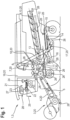
- the agricultural working machine 1 shown schematically and designed as a combine harvester 2 accommodates a grain cutter 3 in its front area, which is connected in a manner known per se to the inclined conveyor 4 of the combine harvester 2 .
- the harvested crop stream 5 passing through the inclined conveyor 4 is transferred in the upper, rear region of the inclined conveyor 4 to the threshing elements 7 of the combine harvester 2 which are at least partially encased by a so-called concave 6 on the underside.
- a deflection drum 8 arranged downstream of the threshing elements 7 deflects the crop flow 5 exiting from the threshing elements 7 in the rear area in such a way that it is transferred directly to a separating device 10 designed as a separating rotor 9 .
- the material flow 5 is conveyed in the rotating separating rotor 9 in such a way that freely movable grains 11 contained in the material flow 5 are separated in the lower area of the separating rotor 9 .
- the separating device 10 embodied as a separating rotor 9 in the exemplary embodiment shown can also be embodied as a tray shaker that is known per se and is therefore not shown.
- Both the grains 11 separated on the concave 6 and on the separating rotor 9 are fed via the return floor 12 and feed floor 13 to a cleaning device 17 consisting of several sieve levels 14, 15 and a blower 16.
- the cleaned grain flow is finally transferred to a grain tank 19 by means of elevators 18 .
- the grain header 3, the inclined conveyor 4, the threshing elements 7 and their associated concave 6, the separating device 10, the cleaning device 17, the elevators 18 and the grain tank 19 are referred to as working elements 20 of the agricultural working machine 1 below.
- the agricultural working machine 1 also has a vehicle cab 21 in which at least one control and regulating device 23 with a display unit 22 is arranged, by means of which a large number of known and therefore not explained in detail, automatically or initiated by the operator 24 of the agricultural working machine 1 processes can be controlled.
- the control and regulating device 23 communicates in a manner known per se with a multiplicity of sensor systems 26 via a so-called bus system 25. Details regarding the structure of the sensor systems 26 are detailed in FIG DE 101 47 733 described so that the structure of the sensor systems 26 is not described again in the following.
- the control and regulation device 23 is coupled to a driver assistance system 28 that includes a display unit 27 .
- driver assistance system 28 can also be integrated directly into the control and regulation device 23 and the visualization of the information 29 provided by the driver assistance system 28 and explained in more detail below can also be directly in that assigned to the control and regulation device 23 Display unit 22 takes place.
- the arithmetic unit 30 is designed in such a way that, in addition to the internal information generated by the sensor systems 26, 31 , external information 32 and information 33 stored in the arithmetic unit 30 itself, such as expert knowledge, can be processed into a large number of output signals 34.
- the output signals 34 are such that they include at least display control signals 35 and working element control signals 36, with the former determining the contents of the display unit 22 and the latter causing the change in the most varied working parameters 37 of the working elements 20 of the agricultural working machine 1, with arrow 37 symbolizing the threshing drum speed stands.
- control and regulating device 23 is coupled to a driver assistance system 28, with the driver assistance system 28 being integrated into the agricultural working machine 1 in such a way that data 38 is transmitted in a manner to be described in more detail both to the control and regulating device 23 as well as with the display unit 22 assigned to it.
- the display unit 22 assigned to the control and regulation device 23 comprises a so-called hotkey window 38 that can be freely defined by the operator 24 and in which important machine information, such as the filling level of the fuel tank 38a, machine parameter settings 38b and the driving speed 38c, is visualized.
- display unit 22 includes display elements 39 for visualizing current values of certain quality parameters 40 of agricultural working machine 1.
- display element 39 arranged on the top visualizes the composition of what is known as “tailings” 41, with the left-hand display showing “tailings volume” 41a and the representation on the right visualizes the "grain portion in the tailings” 41b.
- the lower left display element 39 visualizes the so-called “separation losses” 42, i.e. those grain losses that are discharged from the rear area of the agricultural working machine 1 by the separating device 10 designed as a separating rotor 9 or straw walker and are not conveyed into the grain tank 19.
- the lower right display element 39 visualizes the so-called "cleaning losses" 43, whereby those grain losses are displayed here that are discharged from the agricultural working machine 1 by the cleaning device 17 in a manner analogous to the separating device 10 and are not conveyed into the grain tank 19.
- Each of the display elements 39 also includes a target value indicator 44 designed as a horizontal line, which defines the maximum permissible loss level of the respective quality parameter 40 previously defined by the operator 24, so that the operator 24 can quickly determine whether the agricultural working machine 1 has a sufficient working quality.
- the setting options for the separating device 10 and the cleaning device 17 are stored in so-called setting machines 45.
- an automatic separator 46 for optimizing the mode of operation of the separating device 10 and an automatic cleaning machine 47 for optimizing the mode of operation of the cleaning device 17 are programmed and stored in the control and evaluation device 23 .
- each of the available setting machines 45 can also be stored in whole or in part in the driver assistance system 28 .
- FIG. 3 describes the display unit 22 assigned to the control and regulation device 23 and the available setting machines 45 in more detail with the aid of schematic illustrations.
- Figure 3a shows a schematic structure of the available setting machines 45 for a better understanding of the mode of operation of the same.
- Both the automatic separating device 46 and the automatic cleaning device 47, as well as each automatic setting device 45 provided for the setting of working elements 20 of the agricultural working machine 1, are defined by characteristic curve fields 48.
- the characteristic curves 49 forming a family of characteristics 48 describe various evaluation variables 51 of the agricultural working machine 1 as a function of influencing variables 50.
- the evaluation variable 51 forms the quality parameters 40 described above 10 as well as the speed of the fan 16 assigned to the cleaning device 17 and the opening width of the sieve levels 14, 15.
- the determined operating points 52 are immediately transferred to the family of characteristics 48.
- the agricultural working machine 1 often only works in a small area 53 of the respectively stored family of characteristics 48. So that the family of characteristics 48 stored in the control and regulating device 23 accurately reproduces the separation or cleaning process to be modeled in the entire predefined value range, measuring points 54 are measured at regular intervals approached, which are not in the currently traversed area 53 of the respective family of characteristics 48 and / or in its border areas. This has the effect that the separation or cleaning models stored in the setting machines 45 map the respective process with sufficient accuracy even in the border area of the family of characteristics 48 and in areas of the respective family of characteristics 48 that are currently not being passed through.
- each quality parameter 40 here the "tailings volume” 41a, the "grain fraction in the tailings” 41b, the “separation loss” 42 and the “cleaning loss” 43, is visualized qualitatively in the form of colored areas 55.
- Each of the areas 55 changes its extent depending on the values determined by the control and regulating device 23 for "separation loss” 42, "grain loss” 43 and “tailings composition” 41a, 41b, it being the task of the setting machines 45 to set the quality criteria 40 in an optimum and below the respective setpoint indicator 44 to keep.
- a defined measuring point 54 has to be approached by the setting machine 45, for the exemplary embodiment described here, according to FIG Figures 3c and 3d two activation states 56, 57.
- the automatic separator 46 automatically moves to a measuring point 54 which is either outside of the region 53 just passed through or in the border region of the family of characteristics 48 describing the grain separation on the separating device 10 . So that the operator 24 of the agricultural working machine 1 is informed that the automatic separator 46 is approaching a measuring point 54 that is not in the current working area 53, the area 55 visualizing the quality parameter 40 "separation loss" 42 is faded out in the display unit 22c.
- the size of the area 55 shown as fading is either frozen or that the change in the “separation losses” 42 continues to be visualized.
- the latter variant keeps the operator 24 informed about the course of the change, which before a steady state is reached can also lead to the “separation losses” 42 also briefly exceeding the mark on the setpoint indicator 44 .
- the invention provides that the display element 39 visualizing the "separation loss" 42 is at least partially superimposed by a characteristic symbol 58, while the partially superimposed working and/or quality parameters 37, 40 are displayed passively, preferably fading.
- the structure of the display unit 22 in the further activation state 57 according to 3d be adjusted.
- the automatic cleaning machine 47 automatically moves to a measuring point 54 which is either outside the area 53 just passed through or in the border area of the family of characteristics 48 describing the grain separation on the cleaning device 17 . So that the operator 24 of the agricultural working machine 1 is informed that the automatic cleaning machine 47 is approaching a measuring point 54 that is not in the current working area 53, the quality parameters 40 "cleaning loss" 43, "tailings volume” 41a, "grain proportion in the Tailings” 41b, visualizing areas 55 shown fading.
- the areas 55 shown as fading are either frozen in their size or continue to visualize the change in the “cleaning losses” 43, the “tailings volume” 41a and the “grain proportion in the tailings” 41b.
- the latter variant keeps the operator 24 informed of the course of the changes, which, before a steady state is reached, can also lead to the "cleaning losses” 43, the "tailings volume” 41a and the “grain proportion in the tailings” 41b briefly exceeding the mark of the respective Exceed setpoint indicator 44.
- the invention In order to signal the optimization of a measuring point 54 that is not in the current working area 53 in a way that is clearly visible to the operator 24, the invention also provides that at least the display element 39 visualizing the "loss of cleaning" 43 is at least partially superimposed by a characteristic symbol 58, while the partially superimposed working and/or quality parameters 37, 40 is displayed passively, preferably fading.
- each of the existing setting machines 45 can be activated and deactivated independently of one another, automatically or triggered by the operator 24, so that the number of setting machines 45 working at the same time can be selected as desired. All setting machines 45 are preferably always activated in order to optimize the mode of operation of the agricultural working machine 1 . It is within the scope of the invention that an automatic setting device 45 can also be switched off in a targeted manner by the operator 24 changing a working parameter 37 in a targeted manner by entering a defined value. If the override by the operator 24 takes place while the measuring points 54 are being approached in a targeted manner, the characteristic symbols 58 are hidden and the display of the working and/or quality parameters 37, 40, which may fade, is canceled. In this context, it can also be provided that the operator 24 receives an explicit indication of the deactivation of the setting machine 45 in the display unit 22 .
- control and regulating device 23 Since the control and regulating device 23 is designed in a manner known per se in such a way that it always visualizes the change in the quality parameters 40, regardless of whether automatic setting machines 45 are activated or not, it can be provided in a further embodiment of the invention that the display unit 22 pictograms 59 representing the setting machines 45 are positioned, which are visualized at least highlighted in color when the setting machine 45 is active. The deactivation of the respective setting machine 45 is correspondingly visualized by the respective pictogram 59 being dimmed.
- each setting machine 45 has its own family of characteristics 48, with individual setting machines 45, can also bring about an optimization of the mode of operation of the agricultural working machine 1 with the inclusion of a large number of characteristic curves 48 .
- the cleaning machine 47 takes into account characteristic curves 48, which take into account both the “cleaning losses” 43 and the “tailings volume” 41a and the “grain content in the tailings” 41b.
- the characteristic curve fields 48 taken into account also supply usable values for the evaluation variables 51 and thus for an optimal mode of operation of the agricultural working machine 1, even with fluctuating influencing variables 50, it is provided that the approach is not in the current working area 53 or in the border areas of the characteristic curve fields 48 measuring points 54 in defined time intervals and is limited to a certain number of measuring points 54.
- the number of measuring points 54 that can be selectively controlled is preferably limited to four.
- the defined time intervals, within which the various measuring points 54 are repeatedly controlled, are such that the duration of the time interval increases as the operating time of the agricultural working machine 1 increases and is preferably less than 15 minutes at the beginning of the operating time and increases to 30 minutes as the operating time increases elevated.
- control and regulation device 23 and thus also the setting machines 45 are activated automatically when the agricultural working machine 1 is started up.
- the automatic setting machines 45 are inactive, an indication of an increase in efficiency can be generated for the operator 24 by activating the respective automatic setting machine 45 .
- FIG 4 shows a detailed view of the driver assistance system 28 according to the invention.
- the available process management strategies 61 are first visualized.
- four process management strategies 61 can be selected, namely "balanced"61a;"maximumthroughput”61b;"minimum use of fuel” 61c and "high threshing quality” 61d.
- the driver assistance system 28 regulates the mode of operation of the agricultural working machine 1 in such a way that the maximum possible throughput, at which the predefined target values for a permissible grain loss, consisting of separation loss 42 and cleaning loss 43, are just maintained . If the process control strategy “minimum use of fuel” 61c is selected, the driver assistance system 28 regulates the mode of operation of the agricultural working machine 1 in such a way that the drive energy requirement decreases. This is preferably achieved in that the speed of one or more working elements 20 is reduced.
- driver assistance system 28 works in the process control strategy "high threshing quality" 61b, in addition to low grain losses, low grain breakage and a low admixture proportion in the harvested grain are aimed for.
- the "balanced" control strategy 61a takes into account average levels for all work and/or quality parameters 37, 40 that can be optimized, so that overall a balanced mode of operation of the agricultural working machine 1 results, without certain work and quality parameters 37, 40 being given priority.
- each of the process control strategies 61 can either be selected via the touchscreen function if the display 60 is designed as a touchscreen monitor, or can be activated via a button 63 assigned to the respective process control strategy 61. It is within the scope of the invention that the respective process control strategy 61 can also be activated by means of a rotary-push switch 64 .
- a viewing window 65 is also positioned in the upper area of the display 60, which includes natural-language comments and figure 4 gives an indication of the currently activated process control strategy 61 .
- the driver assistance system 28 is coupled to the control and regulation device 23 assigned to the agricultural working machine 1, it also being conceivable for the driver assistance system 28 and the control and regulation device 23 to be combined in a single structural unit in a manner that is not shown.
- the various work and quality parameters 37, 40 are optimized in the manner already described using the stored characteristic curve fields 48 defined by characteristic curves 49. If the processing unit 30 assigned to the open-loop and closed-loop control device 23 determines that limit values defined within a selected process control strategy 61 for one or more of the quality parameters 40 cannot be maintained or could be lower than specified, the driver assistance system 28 proposes a change in the process control strategy 61 according to the invention.
- figure 5 shows various scenarios for a proposal to change the litigation strategy 61.
- the driver assistance system 28 proposes in natural language form in the viewing window 65 assigned to its display 60 to switch from the process control strategy "balanced" 61a to the process control strategy "high threshing quality” 61d in order to bring about an improvement in grain cleanliness.
- Figure 5b shown how the driver assistance system 28 proposes a change from the process control strategy "high threshing quality” 61d to the process control strategy "maximum throughput" 61b in a natural language manner in order to bring about a reduction in the grain quantity in the so-called tailings.
- This dialog is in turn visualized in the viewing window 65 assigned to the display 60 .
- Figure 5c shows finally a dialogue in which the driver assistance system 28 proposes the activation of the cleaning machine 47, the cleaning machine 47 being part of the process control strategy “high threshing quality” 61d.
- driver assistance system 28 proposes a change in process control strategy 61 if the specified setpoint values of one or more quality parameters 40 cannot be achieved within the selected process control strategy 61 or if driver assistance system 28 recognizes that when a different process control strategy 61 is selected, even more favorable values for one or several of the quality parameters 40 are achievable.
- the operator 24 of the agricultural working machine 1 wants to accept the change in the process control strategy 61 proposed by the driver assistance system 28, he confirms this by activating an "Accept" field 66.
- the optimization process activated as a result is based on an interaction between the operator 24 and the driver assistance system 28.
- the operator 24 in the display unit 22 of the control and regulation device 23 according to the explanations for figures 2 and 3 the changes in the working parameters 37 brought about by the driver assistance system 28 and their effect on the respective quality parameters 40 are displayed.
- the driver assistance system 28 is designed in such a way that the operator 24 has to evaluate the optimization results. Depending on the operator's assessment, the optimization process is continued or terminated.
- the operator 24 is informed about the effects on the working method resulting from a process control strategy change, in that additional natural-language comments, for example on the influence on certain quality parameters 40, are displayed in the respective viewing window 65.
- additional natural-language comments for example on the influence on certain quality parameters 40
- a description of the proposed process management strategy 61 can be called up manually and displayed or automatically overlaid in order to give the operator 24 the option of being able to compare the currently selected process management strategy 61 with the proposed process management strategy.
Description
Die vorliegende Erfindung betrifft ein Fahrerassistenzsystem für eine landwirtschaftliche Arbeitsmaschinen mit zumindest einer Steuer- und Regeleinrichtung gemäß dem Oberbegriff des Anspruches 1.The present invention relates to a driver assistance system for an agricultural working machine with at least one open-loop and closed-loop control device according to the preamble of
Aus dem Stand der Technik ist es bekannt Arbeits- und Qualitätsparameter einer landwirtschaftlichen Arbeitsmaschine mittels einer Steuer- und Regeleinrichtung zu überwachen und zu optimieren. Die
Diese bekannten Optimierungsmethoden gelangen dann an ihre Grenzen, wenn innerhalb einer gewählten Strategie ein zufriedenstellendes Ergebnis nicht erzielt werden kann. Dies ist häufig dann der Fall, wenn die Eigenschaften des zu erntenden Gutes stark von üblicherweise zu erwartenden Ernteguteigenschaften abweichen oder die Beschaffenheit des zu bearbeitenden Territoriums, wie etwa hängiges Gelände, die Arbeitsweise der Arbeitsorgane negativ beeinflusst.These known optimization methods reach their limits when a satisfactory result cannot be achieved within a chosen strategy. This is often the case when the properties of the crop to be harvested deviate greatly from crop properties that are usually to be expected, or the nature of the territory to be processed, such as sloping terrain, negatively influences the way the working units work.
Aufgabe der vorliegenden Erfindung ist es daher, die Steuer- und Regeleinrichtung einer landwirtschaftlichen Arbeitsmaschine derart weiterzuentwickeln, dass eine qualitativ hochwertige Regelung der landwirtschaftlichen Arbeitsmaschine möglich wird.It is therefore the object of the present invention to further develop the control and regulating device of an agricultural working machine in such a way that high-quality regulation of the agricultural working machine becomes possible.
Diese Aufgabe wird erfindungsgemäß durch die kennzeichnenden Merkmale des unabhängigen Anspruches 1 gelöst.According to the invention, this object is achieved by the characterizing features of
Indem das Fahrerassistenzsystem für eine landwirtschaftliche Arbeitsmaschine mit zumindest einer Steuer- und Regeleinrichtung, die mittels in ihr hinterlegter Kennlinienfelder zu einer automatisierbaren Einstellung und Überwachung von Arbeits- und/oder Qualitätsparametern der landwirtschaftlichen Arbeitsmaschine eingerichtet ist und das durch Vorgabe einer auswählbaren Prozessführungsstrategie eine automatisierte Überwachung und/oder Einstellung zumindest eines Arbeits- und/oder Qualitätsparameters der landwirtschaftlichen Arbeitsmaschine erfolgt, wobei das Fahrerassistenzsystem zumindest dann einen Wechsel der Prozessführungsstrategie vorschlägt, wenn der vorgegebene Sollwert eines oder mehrerer Qualitätsparameter innerhalb der vorausgewählten Prozessführungsstrategie nicht erreichbar ist, wird sichergestellt, dass eine qualitativ hochwertige Regelung der landwirtschaftlichen Arbeitsmaschine möglich wird.In that the driver assistance system for an agricultural working machine has at least one control and regulating device, which is set up for automated setting and monitoring of working and/or quality parameters of the agricultural working machine by means of characteristic curves stored in it and which, by specifying a selectable process control strategy, enables automated monitoring and /or setting of at least one working and/or quality parameter of the agricultural working machine takes place, with the driver assistance system at least then suggesting a change in the process control strategy if the specified target value of one or more quality parameters cannot be achieved within the preselected process control strategy, it is ensured that a high-quality Control of the agricultural machine is possible.
In vorteilhafter Ausgestaltung der Erfindung wird die Qualität des Regelungsergebnisses auch dadurch noch verbessert, wenn das Fahrerassistenzsystem zudem einen Wechsel der Prozessführungsstrategie vorschlägt, wenn für einen oder mehrere der Qualitätsparameter noch günstigere als durch den vorgegebenen Sollwert definierte Werte erreichbar sind.In an advantageous embodiment of the invention, the quality of the control result is also improved if the driver assistance system also proposes a change in the process control strategy if values that are even more favorable than those defined by the specified setpoint can be achieved for one or more of the quality parameters.
Eine besonders effektive Optimierung der Qualitätsparameter einer landwirtschaftlichen Arbeitsmaschine ergibt sich gemäß einer weiteren vorteilhaften Ausgestaltung der Erfindung dadurch, dass eine wiederholte Interaktion des Bedieners mit dem Fahrerassistenzsystem zur Optimierung desselben Arbeits- und/oder Qualitätsparameters das Fahrerassistenzsystem veranlasst, einen Wechsel der Prozessführungsstrategie vorzuschlagen.According to a further advantageous embodiment of the invention, a particularly effective optimization of the quality parameters of an agricultural working machine results from the fact that repeated interaction of the operator with the driver assistance system to optimize the same work and/or quality parameter causes the driver assistance system to propose a change in the process control strategy.
Eine für den Bediener leicht verständliche Kommunikation mit dem Fahrerassistenzsystem ergibt sich in einer vorteilhaften Ausgestaltung der Erfindung dann, wenn die Kommunikation mit dem Fahrerassistenzsystem natürlichsprachig erfolgt.In an advantageous embodiment of the invention, communication with the driver assistance system that is easy for the operator to understand results when communication with the driver assistance system takes place in natural language.
Die von dem Fahrerassistenzsystem bewirkte Optimierung der Arbeitsweise der landwirtschaftlichen Arbeitsmaschine ist zudem dann besonders effektvoll, wenn in einer vorteilhaften Weiterbildung der Erfindung die auswählbaren Prozessführungsstrategien zumindest die Prozessführungsstrategien "maximaler Durchsatz", "minimaler Kraftstoffeinsatz", "hohe Druschqualität" und "Ausgeglichen" umfassen.The optimization of the mode of operation of the agricultural working machine brought about by the driver assistance system is also particularly effective if, in an advantageous development of the invention, the process control strategies that can be selected include at least the process control strategies "maximum throughput", "minimum use of fuel", "high threshing quality" and "balanced".
Um den Bediener der landwirtschaftlichen Arbeitsmaschine stets über die Auswirkungen der von dem Fahrerassistenzsystem bewirkten Optimierung informiert zu halten, ist in einer vorteilhaften Ausgestaltung der Erfindung zudem vorgesehen, dass die aus einem Wechsel der Prozessführungsstrategie resultierenden Auswirkungen auf die Arbeitsweise der Erntemaschine im Display des Fahrerassistenzsystems natürlichsprachig eingeblendet werden. Analoge Effekte werden erzielt, wenn gemäß einer weiteren Ausgestaltungsvariante eine Beschreibung der vorgeschlagenen Prozessführungsstrategie auf dem Display des Fahrerassistenzsystems natürlichsprachig darstellbar ist.In order to keep the operator of the agricultural working machine informed about the effects of the optimization brought about by the driver assistance system, an advantageous embodiment of the invention also provides that the effects on the operation of the harvesting machine resulting from a change in the process control strategy are shown in natural language on the display of the driver assistance system become. Similar effects are achieved if according to a further embodiment variant a description of the proposed process control strategy can be displayed in natural language on the display of the driver assistance system.
Eine komplexe Optimierung der landwirtschaftlichen Arbeitsmaschine wird in vorteilhafter Weiterbildung der Erfindung dann erreicht, wenn die Arbeitsparameter Maschinenparametereinstellungen und Erntegutparameter und die Qualitätsparameter die Parameter "Abscheideverlust", "Reinigungsverlust", "Überkehr", "Überkehrvolumen" und "Kornanteil in der Überkehr" umfassen.A complex optimization of the agricultural working machine is achieved in an advantageous development of the invention when the working parameters machine parameter settings and harvested crop parameters and the quality parameters include the parameters "separation loss", "cleaning loss", "tailings", "tailings volume" and "grain proportion in the tailings".
Einen schnellen Überblick über den Aktivierungszustand der verfügbaren Einstellautomaten erhält der Bediener der landwirtschaftlichen Arbeitsmaschine zudem dann, wenn zumindest die die Qualitätskriterien beschreibenden Kennlinienfelder in Einstellautomaten hinterlegt sind und wobei jeder Einstellautomat in der Anzeigeeinheit mittels Piktogramm visualisiert ist und die Aktivierung eines Einstellautomaten durch Hervorhebung des jeweiligen Piktogramms und die Deaktivierung des jeweiligen Einstellautomaten durch Abblendung des jeweiligen Piktogramms visualisiert wird.The operator of the agricultural working machine also gets a quick overview of the activation status of the available setting machines if at least the characteristic fields describing the quality criteria are stored in setting machines and each setting machine is visualized in the display unit by means of a pictogram and the activation of a setting machine is visualized by highlighting the respective pictogram and the deactivation of the respective setting machine is visualized by dimming the respective pictogram.
Damit stets sichergestellt ist, dass die landwirtschaftliche Arbeitsmaschine die verfügbaren Einstellressourcen optimal nutzt, kann zudem vorgesehen sein, dass die Steuer- und Regeleinrichtung automatisch mit der Inbetriebnahme der Arbeitsmaschine aktiviert wird.In order to always ensure that the agricultural working machine optimally uses the available setting resources, it can also be provided that the open-loop and closed-loop control device is activated automatically when the working machine is started up.
Weitere vorteilhafte Ausgestaltungen der Erfindungen sind den Unteransprüchen zu entnehmen und werden nachfolgend anhand von in Zeichnungen dargestellten Ausführungsbeispielen näher erläutert.Further advantageous configurations of the invention can be found in the subclaims and are explained in more detail below with reference to exemplary embodiments illustrated in the drawings.
Es zeigen:
- Fig. 1
- eine schematische Darstellung einer als Mähdrescher ausgeführten landwirtschaftlichen Arbeitsmaschine;
- Fig. 2
- eine schematische Darstellung einer Anzeigestruktur einer Steuer- und Regelungseinrichtung;
- Fig. 3a - 3d
- schematische Darstellungen der Anzeigestruktur der Steuer- und Regelungseinrichtung in unterschiedlichen Betriebssituationen;
Figur 4- eine schematische Darstellung des erfindungsgemäßen Fahrerassistenzsystems;
Figur 5- verschiedene Betriebszustände des erfindungsgemäßen Fahrerassistenzsystems.
- 1
- a schematic representation of an agricultural working machine designed as a combine harvester;
- 2
- a schematic representation of a display structure of a control and regulation device;
- Figures 3a - 3d
- schematic representations of the display structure of the control and regulation device in different operating situations;
- figure 4
- a schematic representation of the driver assistance system according to the invention;
- figure 5
- different operating states of the driver assistance system according to the invention.
Die in
Weiter verfügt die landwirtschaftliche Arbeitsmaschine 1 über eine Fahrzeugkabine 21 in der zumindest eine mit einer Anzeigeeinheit 22 versehene Steuer- und Regeleinrichtung 23 angeordnet ist, mittels derer automatisch oder vom Bediener 24 der landwirtschaftlichen Arbeitsmaschine 1 initiiert eine Vielzahl von an sich bekannten und daher nicht näher erläuterten Prozessen gesteuert werden können. Die Steuer- und Regeleinrichtung 23 kommuniziert über ein sogenanntes Bussystem 25 in an sich bekannter Weise mit einer Vielzahl von Sensorsystemen 26. Einzelheiten bezüglich der Struktur der Sensorsysteme 26 sind detailliert in der
Die Anzeigeeinheit 22 umfasst in ihrem rechtsseitigen Bereich Anzeigeelemente 39 zur Visualisierung aktueller Werte bestimmter Qualitätsparameter 40 der landwirtschaftlichen Arbeitsmaschine 1. Im dargestellten Ausführungsbeispiel visualisiert das obenseitig angeordnete Anzeigeelement 39 die Zusammensetzung der sogenannten "Überkehr" 41, wobei die linkseitige Darstellung das "Überkehrvolumen" 41a und die rechtsseitige Darstellung den "Kornanteil in der Überkehr" 41b visualisiert. Das untere, linke Anzeigeelement 39 visualisiert die sogenannten "Abscheideverluste" 42, d.h. diejenigen Kornverluste, die von der als Trennrotor 9 oder Hordenschüttler ausgeführten Trenneinrichtung 10 im rückwärtigen Bereich der landwirtschaftlichen Arbeitsmaschine 1 aus dieser ausgetragen und nicht in den Korntank 19 gefördert werden. Das untere, rechte Anzeigeelement 39 visualisiert die sogenannten "Reinigungsverluste" 43, wobei hier diejenigen Kornverluste angezeigt werden, die von der Reinigungseinrichtung 17 in analoger Weise zur Trenneinrichtung 10 aus der landwirtschaftlichen Arbeitsmaschine 1 ausgetragen und nicht in den Korntank 19 gefördert werden. Jedes der Anzeigeelemente 39 umfasst zudem einen als waagerechten Strich ausgeführten Sollwertanzeiger 44, der das maximal zulässige und vom Bediener 24 zuvor definierte Verlustniveau des jeweiligen Qualitätsparameters 40 definiert, sodass der Bediener 24 schnell erfassen kann, ob die landwirtschaftliche Arbeitsmaschine 1 eine hinreichende Arbeitsqualität aufweist.In its right-hand area,
Aufgrund der komplexen Zusammenhänge zwischen verschiedensten Maschinenparametern 38a-c und zumindest den Qualitätsparametern 40 sind die Einstelloptionen für die Trenneinrichtung 10 und die Reinigungseinrichtung 17 in sogenannten Einstellautomaten 45 hinterlegt. Im dargestellten Ausführungsbeispiel sind gemäß
Wird die landwirtschaftliche Arbeitsmaschine 1, im hier dargestellten Ausführungsbeispiel der Mähdrescher 2, mit aktiviertem Abscheideautomat 46 und aktiviertem Reinigungsautomat 47 betrieben, hat die der Steuer- und Regeleinrichtung 23 zugeordnete Anzeigeeinheit 22 die in
Muss nun ein definierter Messpunkt 54 durch die Einstellautomaten 45 angefahren werden, ergeben sich für das hier beschriebene Ausführungsbeispiel gemäß den
In analoger Weise kann die Struktur der Anzeigeeinheit 22 in dem weiteren Aktivierungszustand 57 gemäß
In an sich bekannter Weise kann jeder der vorhandenen Einstellautomaten 45 voneinander unabhängig automatisch oder vom Bediener 24 ausgelöst aktiviert und deaktiviert werden, sodass die Anzahl der gleichzeitig arbeitenden Einstellautomaten 45 beliebig wählbar ist. Vorzugsweise sind stets alle Einstellautomaten 45 zur Optimierung der Arbeitsweise der landwirtschaftlichen Arbeitsmaschine 1 aktiviert. Es liegt im Rahmen der Erfindung, dass eine gezielte Abschaltung eines Einstellautomaten 45 auch dadurch bewirkt werden kann, dass der Bediener 24 gezielt einen Arbeitsparameter 37 durch Eingabe eines definierten Wertes ändert. Findet die Übersteuerung durch den Bediener 24 während des gezielten Anfahrens von Messpunkten 54 statt, werden die charakteristischen Symbole 58 ausgeblendet und die gegebenenfalls verblassende Darstellung der Arbeits- und/oder Qualitätsparameter 37, 40 aufgehoben. In diesem Zusammenhang kann zudem vorgesehen sein, das der Bediener 24 in der Anzeigeeinheit 22 einen expliziten Hinweis auf die Deaktivierung von Einstellautomaten 45 erhält.In a manner known per se, each of the existing
Da die Steuer- und Regeleinrichtung 23 in an sich bekannter Weise so beschaffen ist, dass sie stets die Änderung der Qualitätsparameter 40 visualisiert, unabhängig davon, ob Einstellautomaten 45 aktiviert sind oder nicht kann in einer weiteren Ausgestaltung der Erfindung vorgesehen sein, dass in der Anzeigeeinheit 22 die Einstellautomaten 45 repräsentierende Piktogramme 59 positioniert sind, die bei aktivem Einstellautomat 45 zumindest farblich hervorgehoben visualisiert werden. Die Deaktivierung des jeweiligen Einstellautomaten 45 wird entsprechend durch Abblendung des jeweiligen Piktogramms 59 visualisiert.Since the control and regulating
Weiter liegt es im Rahmen der Erfindung, dass jeder Einstellautomat 45 über sein eigenes Kennlinienfeld 48 verfügt, wobei einzelne Einstellautomaten 45, auch unter Einbeziehung einer Vielzahl von Kennlinienfeldern 48 eine Optimierung der Arbeitsweise der landwirtschaftlichen Arbeitsmaschine 1 bewirken können. Im dargestellten Ausführungsbeispiel berücksichtigt der Reinigungsautomat 47 Kennlinienfelder 48, die sowohl die "Reinigunsgverluste" 43 als auch das "Überkehrvolumen" 41a und den "Kornanteil in der Überkehr" 41b berücksichtigen. Damit die berücksichtigten Kennlinienfelder 48 auch bei schwankenden Einflussgrößen 50 brauchbare Werte für die Bewertungsgrößen 51 und damit für eine optimale Arbeitsweise der landwirtschaftlichen Arbeitsmaschine 1 liefern, ist vorgesehen, dass das Anfahren nicht im gegenwärtigen Arbeitsbereich 53 oder in den Grenzbereichen der Kennlinienfelder 48 liegender Messpunkte 54 in definierten zeitlichen Abständen und auf eine bestimmte Anzahl von Messpunkten 54 beschränkt erfolgt. Vorzugsweise ist die Anzahl der gezielt ansteuerbaren Messpunkte 54 auf vier beschränkt. Die definierten Zeitintervalle, innerhalb derer die verschiedenen Messpunkte 54 wiederholt angesteuert werden, sind so beschaffen, dass die Dauer des Zeitintervalls mit zunehmender Einsatzzeit der landwirtschaftlichen Arbeitsmaschine 1 zunimmt und vorzugsweise zu Beginn der Einsatzzeit kleiner als 15 Minuten ist und sich mit zunehmender Einsatzzeit auf 30 Minuten erhöht. Zudem kann vorgesehen sein, dass die Steuer- und Regeleinrichtung 23 und damit auch die Einstellautomaten 45 automatisch mit Inbetriebnahme der landwirtschaftlichen Arbeitsmaschine 1 aktiviert werden. In diesem Zusammenhang kann zudem vorgesehen sein, dass bei inaktiven Einstellautomaten 45 ein Hinweis auf eine Effizienzsteigerung durch Aktivierung des jeweiligen Einstellautomaten 45 an den Bediener 24 generierbar ist.It is also within the scope of the invention that each setting
Wird die Prozessführungsstrategie "maximaler Durchsatz" 61b gewählt, regelt das Fahrerassistenzsystem 28 die Arbeitsweise der landwirtschaftlichen Arbeitsmaschine 1 so, dass der maximal mögliche Durchsatz, bei dem gerade noch die vordefinierten Sollwerte für einen zulässigen Kornverlust, bestehend aus Abscheideverlust 42 und Reinigungsverlust 43, eingehalten werden. Wird die Prozessführungsstrategie "minimaler Kraftstoffeinsatz" 61c gewählt, regelt das Fahrerassistenzsystem 28 die Arbeitsweise der landwirtschaftlichen Arbeitsmaschine 1 so, dass der Antriebsenergiebedarf sinkt. Vorzugsweise wird dies dadurch erreicht, dass die Drehzahl eines oder mehrere Arbeitsorgane 20 reduziert wird. Arbeitet das Fahrerassistenzsystem 28 in der Prozessführungsstrategie "hohe Druschqualität" 61b wird neben niedrigen Kornverlusten ein geringer Körnerbruch und ein niedriger Beimengungsanteil im geernteten Korn angestrebt. Die Regelstrategie "ausgeglichen" 61a berücksichtig für alle optimierbaren Arbeits- und/oder Qualitätsparameter 37, 40 mittlere Niveaus, sodass sich insgesamt eine ausgewogene Arbeitsweise der landwirtschaftlichen Arbeitsmaschine 1 ergibt, ohne dass bestimmten Arbeits- und Qualitätsparametern 37, 40 eine Priorität zukommt.If the process control strategy "maximum throughput" 61b is selected, the
Jede der Prozessführungsstrategien 61 ist je nach Beschaffenheit des das Fahrerassistenzsystem 28 und das Display 60 aufnehmenden Gehäuses 62 entweder via Touchscreen-Funktion auswählbar, wenn das Display 60 als Touchscreen-Monitor ausgebildet ist, oder über eine der jeweiligen Prozessführungsstrategie 61 zugeordnete Taste 63 aktivierbar. Es liegt im Rahmen der Erfindung, dass die Aktivierung der jeweiligen Prozessführungsstrategie 61 auch mittels eines Dreh-Drück-Schalters 64 bewirkbar ist. Im oberen Bereich des Displays 60 ist zudem ein Sichtfenster 65 positioniert, welches natürlichsprachige Kommentare umfasst und in
Gemäß den vorherigen Ausführungen ist das Fahrerassistenzsystem 28 mit der der landwirtschaftlichen Arbeitsmaschine 1 zugeordneten Steuer- und Regeleinrichtung 23 gekoppelt, wobei es auch denkbar ist, dass das Fahrerassistenzsystem 28 und die Steuer- und Regeleinrichtung 23 in nicht dargestellter Weise in einer einzigen Baueinheit zusammengefasst sind. Nachdem eine erste Prozessführungsstrategie 61 durch den Bediener 24 ausgewählt wurde werden die verschiedenen Arbeits- und Qualitätsparameter 37, 40 in der bereits beschriebenen Weise anhand der hinterlegten von Kennlinien 49 definierten Kennlinienfelder 48 optimiert. Ermittelt die der Steuer- und Regeleinrichtung 23 zugeordnete Recheneinheit 30, dass innerhalb einer gewählten Prozessführungsstrategie 61 definierte Grenzwerte für einen oder mehrere der Qualitätsparameter 40 nicht einhaltbar sind oder noch niedriger als vorgegeben sein könnten, schlägt das Fahrerassistenzsystem 28 erfindungsgemäß einen Wechsel der Prozessführungsstrategie 61 vor.According to the previous statements, the
Will der Bediener 24 der landwirtschaftlichen Arbeitsmaschine 1 den vom Fahrerassistenzsystem 28 vorgeschlagenen Wechsel der Prozessführungsstrategie 61 akzeptieren bestätigt er dies durch Aktivierung eines "Übernehmen"-Feldes 66. Der dadurch aktivierte Optimierungsprozess basiert auf einer Interaktion des Bedieners 24 mit dem Fahrerassistenzsystem 28. Während des Optimierungsprozesses werden dem Bediener 24 in der Anzeigeeinheit 22 der Steuer- und Regeleinrichtung 23 gemäß den Erläuterungen zu den
Ein weiterer Aspekt der Auswertung der Interaktion des Bedieners 24 mit dem Fahrerassistenzsystem 28 ist das Registrieren einer wiederholten Interaktion, die das selbe Optimierungsziel betrifft. Diese Feststellung wird herangezogen, um innerhalb des Optimierungsprozesses dieses Optimierungsziel stärker zu gewichten, sodass eine wiederholte Interaktion des Bedieners 24 mit dem Fahrerassistenzsystem 28 zur Optimierung desselben Arbeits- und/oder Qualitätsparameters 37, 40 das Fahrerassistenzsystem 28 veranlasst, einen Wechsel der Prozessführungsstrategie 61 vorzuschlagen.
- 60
- Display
- 61
- Prozessführungsstrategie
- 62
- Gehäuse
- 63
- Taste
- 64
- Dreh-Drück-Schalter
- 65
- Sichtfenster
- 66
- "Übernehmen"-Feld
- 60
- screen
- 61
- litigation strategy
- 62
- Housing
- 63
- button
- 64
- Turn-push switch
- 65
- viewing window
- 66
- "Apply" field
Claims (10)
- Driver assist system for an agricultural working machine comprising at least one open-loop and closed-loop control device which is adapted by means of families of characteristics stored therein for automatable adjustment and monitoring of working and/or quality parameters of the agricultural working machine and which by predetermining a process implementation strategy selectable by an operator (24) effects automated monitoring and/or adjustment of at least one working and/or quality parameter of the agricultural working machine, characterized in that the driver assist system (28) is so configured as to propose a change in the process implementation strategy (61) when the predetermined target value of one or more quality parameters (40) cannot be reached within the process implementation strategy (61) preselected by an operator (24) and wherein each process implementation strategy (61) is allocated several quality parameters (40) and several working parameters (37), wherein the driver assist system (28) is additionally so configured as to propose a change in the process implementation strategy (61) when defined limit values for one or more of the quality parameters (40) can be even lower than predetermined.
- Driver assist system according to claim 1, characterized in that a repeated interaction of the operator (24) with the driver assist system (28) for optimization of the same working and/or quality parameter (37, 40) causes the driver assist system (28) to propose a change in the process implementation strategy (61).
- Driver assist system according to one of the preceding claims, characterized in that the communication of the operator (24) with the driver assist system (28) is effected in natural language.
- Driver assist system according to one of the preceding claims, characterized in that the selectable process implementation strategies (61) include at least the process implementation strategies 'maximum throughput' (61b), 'minimum fuel consumption' (61c), 'high threshing quality' (61d) and 'balanced' (61a), wherein the process implementation strategy 'balanced' (61a) takes account of average levels for all optimizable working and/or quality parameters (37, 40) so that overall a balanced mode of operation of the agricultural working machine (1) is effected without a priority being assigned to given working and quality parameters (37, 40).
- Driver assist system according to one of the preceding claims, characterized in that effects resulting from a change in the process implementation strategy (61) on the mode of operation of the agricultural working machine (1) are merged in natural language in the display (60) of the driver assist system (28).
- Driver assist system according to one of the preceding claims, characterized in that a description of the proposed process implementation strategy (61) can be represented in natural language in the display (60) of the driver assist system (28).
- Driver assist system according to one of the preceding claims, characterized in that the working parameters (37) can include machine parameter settings (38b) and crop material parameters.
- Driver assist system according to one of the preceding claims, characterized in that the quality parameters (40) include the parameters 'separation loss' (42), 'cleaning loss' (43), 'tailings' (41), 'tailings volume' (41a) and 'grain proportion in the tailings' (41b).
- Driver assist system according to one of the preceding claims, characterized in that at least the families of characteristics (48) describing the quality criteria (40) are stored in automatic adjustment means (45), and wherein each automatic adjustment means (48) is visualized in the display unit (22) by means of an icon (59) and activation of an automatic adjustment means (45) is visualized by emphasizing the respective icon (59) and de-activation of the respective automatic adjustment means (45) is visualized by dimming the respective icon (59).
- Driver assist system according to one of the preceding claims, characterized in that the open-loop and closed-loop control device (23) can be activated automatically with start-up of the working machine (1).
Priority Applications (1)
| Application Number | Priority Date | Filing Date | Title |
|---|---|---|---|
| PL13172039T PL2687923T3 (en) | 2012-07-16 | 2013-06-14 | Driver assistance system for agricultural vehicle |
Applications Claiming Priority (2)
| Application Number | Priority Date | Filing Date | Title |
|---|---|---|---|
| DE102012106390 | 2012-07-16 | ||
| DE102013106131.1A DE102013106131A1 (en) | 2012-07-16 | 2013-06-13 | Driver assistance system for agricultural machine |
Publications (4)
| Publication Number | Publication Date |
|---|---|
| EP2687923A2 EP2687923A2 (en) | 2014-01-22 |
| EP2687923A3 EP2687923A3 (en) | 2017-11-29 |
| EP2687923B1 EP2687923B1 (en) | 2020-08-05 |
| EP2687923B2 true EP2687923B2 (en) | 2023-05-03 |
Family
ID=48670393
Family Applications (1)
| Application Number | Title | Priority Date | Filing Date |
|---|---|---|---|
| EP13172039.3A Active EP2687923B2 (en) | 2012-07-16 | 2013-06-14 | Driver assistance system for agricultural vehicle |
Country Status (7)
| Country | Link |
|---|---|
| US (1) | US8935060B2 (en) |
| EP (1) | EP2687923B2 (en) |
| DE (1) | DE102013106131A1 (en) |
| HU (1) | HUE051548T2 (en) |
| PL (1) | PL2687923T3 (en) |
| RU (1) | RU2612444C2 (en) |
| UA (1) | UA116758C2 (en) |
Families Citing this family (50)
| Publication number | Priority date | Publication date | Assignee | Title |
|---|---|---|---|---|
| US10318138B2 (en) * | 2011-03-11 | 2019-06-11 | Intelligent Agricultural Solutions Llc | Harvesting machine capable of automatic adjustment |
| US10321624B2 (en) | 2011-03-11 | 2019-06-18 | Intelligent Agriculture Solutions LLC | Air seeder manifold system |
| DE102013106128A1 (en) * | 2012-07-16 | 2014-06-12 | Claas Selbstfahrende Erntemaschinen Gmbh | Agricultural work machine with at least one control device |
| EP2979537B1 (en) | 2013-03-27 | 2019-08-28 | Kubota Corporation | Combine |
| US9403536B2 (en) * | 2013-08-12 | 2016-08-02 | Deere & Company | Driver assistance system |
| US10453018B2 (en) | 2014-01-14 | 2019-10-22 | Deere & Company | Agricultural information sensing and retrieval |
| US10311527B2 (en) | 2014-01-14 | 2019-06-04 | Deere & Company | Agronomic variation and team performance analysis |
| US10380704B2 (en) * | 2014-01-14 | 2019-08-13 | Deere & Company | Operator performance recommendation generation |
| US9892376B2 (en) | 2014-01-14 | 2018-02-13 | Deere & Company | Operator performance report generation |
| DE102014216593A1 (en) * | 2014-08-21 | 2016-02-25 | Deere & Company | Operator assistance system for an agricultural working machine |
| CA2961204C (en) | 2014-09-12 | 2023-01-03 | Appareo Systems, Llc | Non-image-based grain quality sensor |
| US9934538B2 (en) | 2014-09-24 | 2018-04-03 | Deere & Company | Recalling crop-specific performance targets for controlling a mobile machine |
| US9901031B2 (en) | 2014-09-24 | 2018-02-27 | Deere & Company | Automatic tuning of an intelligent combine |
| CN104737721B (en) * | 2015-03-04 | 2016-08-31 | 江苏大学 | A kind of combined harvester self adaptation cleans control device and self adaptation cleans method |
| DE102015106302A1 (en) * | 2015-04-24 | 2016-10-27 | Claas Selbstfahrende Erntemaschinen Gmbh | Harvesting system with a self-propelled harvester |
| DE102015113527A1 (en) * | 2015-08-17 | 2017-02-23 | Claas Selbstfahrende Erntemaschinen Gmbh | Agricultural harvester |
| DE102015121210A1 (en) | 2015-12-07 | 2017-06-08 | Claas Selbstfahrende Erntemaschinen Gmbh | Agricultural working machine |
| DE102015122269A1 (en) | 2015-12-18 | 2017-06-22 | Claas Selbstfahrende Erntemaschinen Gmbh | Method for operating a combine harvester |
| USD823318S1 (en) * | 2016-12-20 | 2018-07-17 | Agco Corporation | Display screen or portion thereof with graphical user interface |
| USD822683S1 (en) * | 2016-12-20 | 2018-07-10 | Agco Corporation | Display screen or portion thereof with graphical user interface |
| US10618362B2 (en) | 2017-01-31 | 2020-04-14 | Deere & Company | Pin-drop hitch mount assembly with alignment features for aligning drawbar and drawbar receiver |
| US10556472B2 (en) | 2017-01-31 | 2020-02-11 | Deere & Company | Pin-drop hitch mount assembly with biased pin retainer mechanism |
| US10589580B2 (en) | 2017-01-31 | 2020-03-17 | Deere & Company | Pin-drop hitch mount assembly with biased pin retainer mechanism |
| US10618361B2 (en) | 2017-01-31 | 2020-04-14 | Deere & Company | Pin-drop hitch mount assembly with biased pin retainer mechanism |
| DE102017105487A1 (en) | 2017-03-15 | 2018-09-20 | Amazonen-Werke H. Dreyer Gmbh & Co. Kg | Agricultural terminal |
| DE102017105495A1 (en) * | 2017-03-15 | 2018-09-20 | Amazonen-Werke H. Dreyer Gmbh & Co. Kg | Agricultural machine system |
| DE102017109849A1 (en) * | 2017-05-08 | 2018-11-08 | Claas Selbstfahrende Erntemaschinen Gmbh | Method for processing an agricultural harvesting process |
| US10437243B2 (en) | 2017-06-19 | 2019-10-08 | Deere & Company | Combine harvester control interface for operator and/or remote user |
| US10310455B2 (en) | 2017-06-19 | 2019-06-04 | Deere & Company | Combine harvester control and communication system |
| US10694668B2 (en) | 2017-06-19 | 2020-06-30 | Deere & Company | Locally controlling settings on a combine harvester based on a remote settings adjustment |
| US11789413B2 (en) | 2017-06-19 | 2023-10-17 | Deere & Company | Self-learning control system for a mobile machine |
| US11589507B2 (en) | 2017-06-19 | 2023-02-28 | Deere & Company | Combine harvester control interface for operator and/or remote user |
| DE102017122300A1 (en) * | 2017-09-26 | 2019-03-28 | Claas Selbstfahrende Erntemaschinen Gmbh | working machine |
| US11076531B2 (en) | 2018-01-23 | 2021-08-03 | Deere & Company | State machine for multiple input-multiple output harvester control |
| DE102018104286A1 (en) * | 2018-02-26 | 2019-08-29 | Claas Selbstfahrende Erntemaschinen Gmbh | Self-propelled forage harvester |
| DE102018104287A1 (en) * | 2018-02-26 | 2019-08-29 | Claas Selbstfahrende Erntemaschinen Gmbh | Forage harvester and method for operating a forage harvester |
| EP3761776B1 (en) * | 2018-03-05 | 2022-12-21 | Agco Corporation | Harvesting machine with visualization system |
| DE102018108494A1 (en) | 2018-04-10 | 2019-10-10 | Claas Selbstfahrende Erntemaschinen Gmbh | Agricultural working machine |
| DE102018111076A1 (en) * | 2018-05-08 | 2019-11-14 | Claas Selbstfahrende Erntemaschinen Gmbh | Harvester |
| DE102018111077A1 (en) | 2018-05-08 | 2019-11-14 | Claas Selbstfahrende Erntemaschinen Gmbh | Combine harvester and method for operating a combine harvester |
| US10782672B2 (en) * | 2018-05-15 | 2020-09-22 | Deere & Company | Machine control system using performance score based setting adjustment |
| US11818982B2 (en) | 2018-09-18 | 2023-11-21 | Deere & Company | Grain quality control system and method |
| US11197417B2 (en) * | 2018-09-18 | 2021-12-14 | Deere & Company | Grain quality control system and method |
| US11375662B2 (en) * | 2019-06-12 | 2022-07-05 | Cnh Industrial America Llc | Apparatus and method for monitoring grain content within a tailings system of an agricultural harvester |
| DE102019122114A1 (en) * | 2019-08-16 | 2021-02-18 | Claas Tractor Sas | Agricultural tractor |
| US11821176B2 (en) * | 2019-08-30 | 2023-11-21 | Deere & Company | Supervisory and improvement system for machine control |
| EP3845050B1 (en) * | 2019-12-30 | 2023-11-29 | AGCO Corporation | Methods and systems for measuring organic material throughput data of harvested crops |
| US11685412B2 (en) * | 2020-03-05 | 2023-06-27 | Caterpillar Paving Products Inc. | Override of autonomous functions of a machine |
| US11620864B2 (en) * | 2020-05-19 | 2023-04-04 | Caterpillar Paving Products Inc. | Systems and methods for viewing onboard machine data |
| CN112965682A (en) * | 2021-04-08 | 2021-06-15 | 上海三一重机股份有限公司 | Auxiliary display method, device and system for working machine and electronic equipment |
Citations (3)
| Publication number | Priority date | Publication date | Assignee | Title |
|---|---|---|---|---|
| EP2165591A1 (en) † | 2008-09-19 | 2010-03-24 | CNH Belgium N.V. | Control system for an agricultural harvesting machine |
| DE102009009767A1 (en) † | 2009-02-20 | 2010-08-26 | Claas Selbstfahrende Erntemaschinen Gmbh | Driver assistance system for agricultural machine |
| DE102010017676A1 (en) † | 2010-07-01 | 2012-01-05 | Claas Selbstfahrende Erntemaschinen Gmbh | Driver assistance system for agricultural machine |
Family Cites Families (16)
| Publication number | Priority date | Publication date | Assignee | Title |
|---|---|---|---|---|
| SU1281197A1 (en) * | 1983-06-15 | 1987-01-07 | Производственное Объединение "Гомсельмаш" | System for automatic control of harvesting machine modes of operation |
| DE4341834C1 (en) * | 1993-12-08 | 1995-04-20 | Claas Ohg | Agricultural machine, in particular combine harvester, with multiprocessor guiding device |
| DE19514223B4 (en) * | 1995-04-15 | 2005-06-23 | Claas Kgaa Mbh | Method for optimizing the use of agricultural machinery |
| DE10147733A1 (en) | 2001-09-27 | 2003-04-10 | Claas Selbstfahr Erntemasch | Method and device for determining a harvester setting |
| US6726559B2 (en) * | 2002-05-14 | 2004-04-27 | Deere & Company | Harvester with control system considering operator feedback |
| DE10329932A1 (en) * | 2003-07-02 | 2005-02-24 | Claas Selbstfahrende Erntemaschinen Gmbh | Method and device for operating machines |
| EP1516522B2 (en) * | 2003-09-19 | 2023-03-29 | CLAAS Selbstfahrende Erntemaschinen GmbH | Method and device for determining the amount of tailings return |
| DE10360597A1 (en) * | 2003-12-19 | 2005-07-28 | Claas Selbstfahrende Erntemaschinen Gmbh | Method and device for controlling working elements of a combine harvester |
| DE102004048083A1 (en) * | 2004-09-30 | 2006-04-06 | Claas Selbstfahrende Erntemaschinen Gmbh | Scalable function windows within a display unit |
| DE102004059543A1 (en) * | 2004-12-09 | 2006-06-29 | Claas Selbstfahrende Erntemaschinen Gmbh | Agricultural working machine |
| DE102005014278A1 (en) * | 2005-03-24 | 2006-10-05 | Claas Selbstfahrende Erntemaschinen Gmbh | Method for determining a target setting value |
| DE102005026159A1 (en) * | 2005-06-06 | 2007-01-25 | Claas Selbstfahrende Erntemaschinen Gmbh | Method for controlling a harvesting machine |
| DE102006044628A1 (en) | 2006-09-19 | 2008-04-03 | Claas Selbstfahrende Erntemaschinen Gmbh | Method for controlling a display device in a harvester |
| DE102007046678A1 (en) * | 2007-09-27 | 2009-04-09 | Claas Selbstfahrende Erntemaschinen Gmbh | Agricultural work vehicle |
| DE102007055074A1 (en) * | 2007-11-16 | 2009-05-20 | Claas Selbstfahrende Erntemaschinen Gmbh | Self-propelled agricultural machine |
| DE102008027906A1 (en) * | 2008-06-12 | 2009-12-17 | Claas Selbstfahrende Erntemaschinen Gmbh | Agricultural harvester |
-
2013
- 2013-06-13 DE DE102013106131.1A patent/DE102013106131A1/en not_active Withdrawn
- 2013-06-14 HU HUE13172039A patent/HUE051548T2/en unknown
- 2013-06-14 PL PL13172039T patent/PL2687923T3/en unknown
- 2013-06-14 EP EP13172039.3A patent/EP2687923B2/en active Active
- 2013-07-09 UA UAA201308653A patent/UA116758C2/en unknown
- 2013-07-10 RU RU2013131445A patent/RU2612444C2/en active
- 2013-07-16 US US13/942,832 patent/US8935060B2/en active Active
Patent Citations (3)
| Publication number | Priority date | Publication date | Assignee | Title |
|---|---|---|---|---|
| EP2165591A1 (en) † | 2008-09-19 | 2010-03-24 | CNH Belgium N.V. | Control system for an agricultural harvesting machine |
| DE102009009767A1 (en) † | 2009-02-20 | 2010-08-26 | Claas Selbstfahrende Erntemaschinen Gmbh | Driver assistance system for agricultural machine |
| DE102010017676A1 (en) † | 2010-07-01 | 2012-01-05 | Claas Selbstfahrende Erntemaschinen Gmbh | Driver assistance system for agricultural machine |
Also Published As
| Publication number | Publication date |
|---|---|
| EP2687923B1 (en) | 2020-08-05 |
| RU2612444C2 (en) | 2017-03-09 |
| EP2687923A3 (en) | 2017-11-29 |
| UA116758C2 (en) | 2018-05-10 |
| US20140019018A1 (en) | 2014-01-16 |
| EP2687923A2 (en) | 2014-01-22 |
| PL2687923T3 (en) | 2021-01-11 |
| DE102013106131A1 (en) | 2014-06-12 |
| US8935060B2 (en) | 2015-01-13 |
| HUE051548T2 (en) | 2021-03-01 |
| RU2013131445A (en) | 2015-01-20 |
Similar Documents
| Publication | Publication Date | Title |
|---|---|---|
| EP2687923B2 (en) | Driver assistance system for agricultural vehicle | |
| EP2687924B1 (en) | Self-propelled agricultural machine | |
| EP4155839A1 (en) | Agricultural machine with at least one control device | |
| EP1731017B2 (en) | Method for controlling a harvesting machine | |
| EP3459338B1 (en) | Work machine | |
| EP3178307B1 (en) | Agricultural work machine | |
| EP1543712B1 (en) | Method and device for regulating the working means of a combine | |
| EP2220925B1 (en) | Agricultural vehicle and display unit for same | |
| EP1704767B1 (en) | Method for determining an optimal setting | |
| EP2322028B1 (en) | Driver assistance system for agricultural workmachine | |
| EP1763988B1 (en) | Method for regulation of a working unit of a harvesting machine | |
| EP2042019B1 (en) | Agricultural work vehicle | |
| EP2728523A1 (en) | Assistance system for optimising vehicle operation | |
| EP2401905A2 (en) | Method for adjusting at least one working part of a self-propelled harvester | |
| DE102007022899A1 (en) | Agricultural working machine | |
| EP2853144A1 (en) | Agricultural machine comprising a display device | |
| EP1902609B1 (en) | Method for controlling a display device in a harvester | |
| EP1900272B1 (en) | Agricltural working machine | |
| EP2110012A2 (en) | Method and device for optimising operational parameters of an agricultural work machine | |
| EP1321024B2 (en) | Method and device for optimising the operation of an agricultural vehicle | |
| EP3501255B1 (en) | Agricultural working machine for executing an agricultural work process | |
| EP4091435A1 (en) | Method for determining the need to sharpen chopping knives of a chopping device |
Legal Events
| Date | Code | Title | Description |
|---|---|---|---|
| PUAI | Public reference made under article 153(3) epc to a published international application that has entered the european phase |
Free format text: ORIGINAL CODE: 0009012 |
|
| AK | Designated contracting states |
Kind code of ref document: A2 Designated state(s): AL AT BE BG CH CY CZ DE DK EE ES FI FR GB GR HR HU IE IS IT LI LT LU LV MC MK MT NL NO PL PT RO RS SE SI SK SM TR |
|
| AX | Request for extension of the european patent |
Extension state: BA ME |
|
| RAP1 | Party data changed (applicant data changed or rights of an application transferred) |
Owner name: CLAAS SELBSTFAHRENDE ERNTEMASCHINEN GMBH |
|
| PUAL | Search report despatched |
Free format text: ORIGINAL CODE: 0009013 |
|
| AK | Designated contracting states |
Kind code of ref document: A3 Designated state(s): AL AT BE BG CH CY CZ DE DK EE ES FI FR GB GR HR HU IE IS IT LI LT LU LV MC MK MT NL NO PL PT RO RS SE SI SK SM TR |
|
| AX | Request for extension of the european patent |
Extension state: BA ME |
|
| RIC1 | Information provided on ipc code assigned before grant |
Ipc: G05B 13/02 20060101AFI20171020BHEP Ipc: A01D 41/127 20060101ALI20171020BHEP |
|
| STAA | Information on the status of an ep patent application or granted ep patent |
Free format text: STATUS: REQUEST FOR EXAMINATION WAS MADE |
|
| 17P | Request for examination filed |
Effective date: 20180529 |
|
| RBV | Designated contracting states (corrected) |
Designated state(s): AL AT BE BG CH CY CZ DE DK EE ES FI FR GB GR HR HU IE IS IT LI LT LU LV MC MK MT NL NO PL PT RO RS SE SI SK SM TR |
|
| STAA | Information on the status of an ep patent application or granted ep patent |
Free format text: STATUS: EXAMINATION IS IN PROGRESS |
|
| 17Q | First examination report despatched |
Effective date: 20190624 |
|
| GRAP | Despatch of communication of intention to grant a patent |
Free format text: ORIGINAL CODE: EPIDOSNIGR1 |
|
| STAA | Information on the status of an ep patent application or granted ep patent |
Free format text: STATUS: GRANT OF PATENT IS INTENDED |
|
| INTG | Intention to grant announced |
Effective date: 20200310 |
|
| GRAS | Grant fee paid |
Free format text: ORIGINAL CODE: EPIDOSNIGR3 |
|
| GRAA | (expected) grant |
Free format text: ORIGINAL CODE: 0009210 |
|
| STAA | Information on the status of an ep patent application or granted ep patent |
Free format text: STATUS: THE PATENT HAS BEEN GRANTED |
|
| AK | Designated contracting states |
Kind code of ref document: B1 Designated state(s): AL AT BE BG CH CY CZ DE DK EE ES FI FR GB GR HR HU IE IS IT LI LT LU LV MC MK MT NL NO PL PT RO RS SE SI SK SM TR |
|
| REG | Reference to a national code |
Ref country code: GB Ref legal event code: FG4D Free format text: NOT ENGLISH |
|
| REG | Reference to a national code |
Ref country code: CH Ref legal event code: EP |
|
| REG | Reference to a national code |
Ref country code: AT Ref legal event code: REF Ref document number: 1299579 Country of ref document: AT Kind code of ref document: T Effective date: 20200815 |
|
| REG | Reference to a national code |
Ref country code: DE Ref legal event code: R096 Ref document number: 502013014977 Country of ref document: DE |
|
| REG | Reference to a national code |
Ref country code: IE Ref legal event code: FG4D Free format text: LANGUAGE OF EP DOCUMENT: GERMAN |
|
| REG | Reference to a national code |
Ref country code: LT Ref legal event code: MG4D |
|
| REG | Reference to a national code |
Ref country code: NL Ref legal event code: MP Effective date: 20200805 |
|
| PG25 | Lapsed in a contracting state [announced via postgrant information from national office to epo] |
Ref country code: PT Free format text: LAPSE BECAUSE OF FAILURE TO SUBMIT A TRANSLATION OF THE DESCRIPTION OR TO PAY THE FEE WITHIN THE PRESCRIBED TIME-LIMIT Effective date: 20201207 Ref country code: GR Free format text: LAPSE BECAUSE OF FAILURE TO SUBMIT A TRANSLATION OF THE DESCRIPTION OR TO PAY THE FEE WITHIN THE PRESCRIBED TIME-LIMIT Effective date: 20201106 Ref country code: ES Free format text: LAPSE BECAUSE OF FAILURE TO SUBMIT A TRANSLATION OF THE DESCRIPTION OR TO PAY THE FEE WITHIN THE PRESCRIBED TIME-LIMIT Effective date: 20200805 Ref country code: SE Free format text: LAPSE BECAUSE OF FAILURE TO SUBMIT A TRANSLATION OF THE DESCRIPTION OR TO PAY THE FEE WITHIN THE PRESCRIBED TIME-LIMIT Effective date: 20200805 Ref country code: HR Free format text: LAPSE BECAUSE OF FAILURE TO SUBMIT A TRANSLATION OF THE DESCRIPTION OR TO PAY THE FEE WITHIN THE PRESCRIBED TIME-LIMIT Effective date: 20200805 Ref country code: FI Free format text: LAPSE BECAUSE OF FAILURE TO SUBMIT A TRANSLATION OF THE DESCRIPTION OR TO PAY THE FEE WITHIN THE PRESCRIBED TIME-LIMIT Effective date: 20200805 Ref country code: LT Free format text: LAPSE BECAUSE OF FAILURE TO SUBMIT A TRANSLATION OF THE DESCRIPTION OR TO PAY THE FEE WITHIN THE PRESCRIBED TIME-LIMIT Effective date: 20200805 Ref country code: NO Free format text: LAPSE BECAUSE OF FAILURE TO SUBMIT A TRANSLATION OF THE DESCRIPTION OR TO PAY THE FEE WITHIN THE PRESCRIBED TIME-LIMIT Effective date: 20201105 Ref country code: BG Free format text: LAPSE BECAUSE OF FAILURE TO SUBMIT A TRANSLATION OF THE DESCRIPTION OR TO PAY THE FEE WITHIN THE PRESCRIBED TIME-LIMIT Effective date: 20201105 |
|
| PG25 | Lapsed in a contracting state [announced via postgrant information from national office to epo] |
Ref country code: NL Free format text: LAPSE BECAUSE OF FAILURE TO SUBMIT A TRANSLATION OF THE DESCRIPTION OR TO PAY THE FEE WITHIN THE PRESCRIBED TIME-LIMIT Effective date: 20200805 Ref country code: RS Free format text: LAPSE BECAUSE OF FAILURE TO SUBMIT A TRANSLATION OF THE DESCRIPTION OR TO PAY THE FEE WITHIN THE PRESCRIBED TIME-LIMIT Effective date: 20200805 Ref country code: LV Free format text: LAPSE BECAUSE OF FAILURE TO SUBMIT A TRANSLATION OF THE DESCRIPTION OR TO PAY THE FEE WITHIN THE PRESCRIBED TIME-LIMIT Effective date: 20200805 Ref country code: IS Free format text: LAPSE BECAUSE OF FAILURE TO SUBMIT A TRANSLATION OF THE DESCRIPTION OR TO PAY THE FEE WITHIN THE PRESCRIBED TIME-LIMIT Effective date: 20201205 |
|
| REG | Reference to a national code |
Ref country code: HU Ref legal event code: AG4A Ref document number: E051548 Country of ref document: HU |
|
| REG | Reference to a national code |
Ref country code: DE Ref legal event code: R026 Ref document number: 502013014977 Country of ref document: DE |
|
| PLBI | Opposition filed |
Free format text: ORIGINAL CODE: 0009260 |
|
| PG25 | Lapsed in a contracting state [announced via postgrant information from national office to epo] |
Ref country code: SM Free format text: LAPSE BECAUSE OF FAILURE TO SUBMIT A TRANSLATION OF THE DESCRIPTION OR TO PAY THE FEE WITHIN THE PRESCRIBED TIME-LIMIT Effective date: 20200805 Ref country code: RO Free format text: LAPSE BECAUSE OF FAILURE TO SUBMIT A TRANSLATION OF THE DESCRIPTION OR TO PAY THE FEE WITHIN THE PRESCRIBED TIME-LIMIT Effective date: 20200805 Ref country code: CZ Free format text: LAPSE BECAUSE OF FAILURE TO SUBMIT A TRANSLATION OF THE DESCRIPTION OR TO PAY THE FEE WITHIN THE PRESCRIBED TIME-LIMIT Effective date: 20200805 Ref country code: EE Free format text: LAPSE BECAUSE OF FAILURE TO SUBMIT A TRANSLATION OF THE DESCRIPTION OR TO PAY THE FEE WITHIN THE PRESCRIBED TIME-LIMIT Effective date: 20200805 Ref country code: DK Free format text: LAPSE BECAUSE OF FAILURE TO SUBMIT A TRANSLATION OF THE DESCRIPTION OR TO PAY THE FEE WITHIN THE PRESCRIBED TIME-LIMIT Effective date: 20200805 |
|
| 26 | Opposition filed |
Opponent name: DEERE & COMPANY/JOHN DEERE GMBH & CO. KG Effective date: 20210407 |
|
| PLAX | Notice of opposition and request to file observation + time limit sent |
Free format text: ORIGINAL CODE: EPIDOSNOBS2 |
|
| PG25 | Lapsed in a contracting state [announced via postgrant information from national office to epo] |
Ref country code: AL Free format text: LAPSE BECAUSE OF FAILURE TO SUBMIT A TRANSLATION OF THE DESCRIPTION OR TO PAY THE FEE WITHIN THE PRESCRIBED TIME-LIMIT Effective date: 20200805 |
|
| PG25 | Lapsed in a contracting state [announced via postgrant information from national office to epo] |
Ref country code: SK Free format text: LAPSE BECAUSE OF FAILURE TO SUBMIT A TRANSLATION OF THE DESCRIPTION OR TO PAY THE FEE WITHIN THE PRESCRIBED TIME-LIMIT Effective date: 20200805 |
|
| PG25 | Lapsed in a contracting state [announced via postgrant information from national office to epo] |
Ref country code: SI Free format text: LAPSE BECAUSE OF FAILURE TO SUBMIT A TRANSLATION OF THE DESCRIPTION OR TO PAY THE FEE WITHIN THE PRESCRIBED TIME-LIMIT Effective date: 20200805 |
|
| PLBB | Reply of patent proprietor to notice(s) of opposition received |
Free format text: ORIGINAL CODE: EPIDOSNOBS3 |
|
| PG25 | Lapsed in a contracting state [announced via postgrant information from national office to epo] |
Ref country code: MC Free format text: LAPSE BECAUSE OF FAILURE TO SUBMIT A TRANSLATION OF THE DESCRIPTION OR TO PAY THE FEE WITHIN THE PRESCRIBED TIME-LIMIT Effective date: 20200805 |
|
| REG | Reference to a national code |
Ref country code: CH Ref legal event code: PL |
|
| GBPC | Gb: european patent ceased through non-payment of renewal fee |
Effective date: 20210614 |
|
| PG25 | Lapsed in a contracting state [announced via postgrant information from national office to epo] |
Ref country code: LU Free format text: LAPSE BECAUSE OF NON-PAYMENT OF DUE FEES Effective date: 20210614 |
|
| PG25 | Lapsed in a contracting state [announced via postgrant information from national office to epo] |
Ref country code: LI Free format text: LAPSE BECAUSE OF NON-PAYMENT OF DUE FEES Effective date: 20210630 Ref country code: IE Free format text: LAPSE BECAUSE OF NON-PAYMENT OF DUE FEES Effective date: 20210614 Ref country code: GB Free format text: LAPSE BECAUSE OF NON-PAYMENT OF DUE FEES Effective date: 20210614 Ref country code: CH Free format text: LAPSE BECAUSE OF NON-PAYMENT OF DUE FEES Effective date: 20210630 |
|
| REG | Reference to a national code |
Ref country code: AT Ref legal event code: MM01 Ref document number: 1299579 Country of ref document: AT Kind code of ref document: T Effective date: 20210614 |
|
| PGFP | Annual fee paid to national office [announced via postgrant information from national office to epo] |
Ref country code: PL Payment date: 20220603 Year of fee payment: 10 |
|
| PG25 | Lapsed in a contracting state [announced via postgrant information from national office to epo] |
Ref country code: AT Free format text: LAPSE BECAUSE OF NON-PAYMENT OF DUE FEES Effective date: 20210614 |
|
| PUAH | Patent maintained in amended form |
Free format text: ORIGINAL CODE: 0009272 |
|
| STAA | Information on the status of an ep patent application or granted ep patent |
Free format text: STATUS: PATENT MAINTAINED AS AMENDED |
|
| 27A | Patent maintained in amended form |
Effective date: 20230503 |
|
| AK | Designated contracting states |
Kind code of ref document: B2 Designated state(s): AL AT BE BG CH CY CZ DE DK EE ES FI FR GB GR HR HU IE IS IT LI LT LU LV MC MK MT NL NO PL PT RO RS SE SI SK SM TR |
|
| REG | Reference to a national code |
Ref country code: DE Ref legal event code: R102 Ref document number: 502013014977 Country of ref document: DE |
|
| P01 | Opt-out of the competence of the unified patent court (upc) registered |
Effective date: 20230515 |
|
| PG25 | Lapsed in a contracting state [announced via postgrant information from national office to epo] |
Ref country code: CY Free format text: LAPSE BECAUSE OF FAILURE TO SUBMIT A TRANSLATION OF THE DESCRIPTION OR TO PAY THE FEE WITHIN THE PRESCRIBED TIME-LIMIT Effective date: 20200805 |
|
| PGFP | Annual fee paid to national office [announced via postgrant information from national office to epo] |
Ref country code: FR Payment date: 20230627 Year of fee payment: 11 Ref country code: DE Payment date: 20230620 Year of fee payment: 11 |
|
| PGFP | Annual fee paid to national office [announced via postgrant information from national office to epo] |
Ref country code: HU Payment date: 20230622 Year of fee payment: 11 |
|
| PGFP | Annual fee paid to national office [announced via postgrant information from national office to epo] |
Ref country code: BE Payment date: 20230620 Year of fee payment: 11 |
|
| PGFP | Annual fee paid to national office [announced via postgrant information from national office to epo] |
Ref country code: IT Payment date: 20230623 Year of fee payment: 11 |