EP2687761A1 - Sealing device - Google Patents
Sealing device Download PDFInfo
- Publication number
- EP2687761A1 EP2687761A1 EP12760861.0A EP12760861A EP2687761A1 EP 2687761 A1 EP2687761 A1 EP 2687761A1 EP 12760861 A EP12760861 A EP 12760861A EP 2687761 A1 EP2687761 A1 EP 2687761A1
- Authority
- EP
- European Patent Office
- Prior art keywords
- seal lip
- convexities
- concavities
- lip
- sealing device
- Prior art date
- Legal status (The legal status is an assumption and is not a legal conclusion. Google has not performed a legal analysis and makes no representation as to the accuracy of the status listed.)
- Granted
Links
- 238000007789 sealing Methods 0.000 title claims abstract description 53
- 239000004519 grease Substances 0.000 claims abstract description 51
- 239000002199 base oil Substances 0.000 claims abstract description 33
- 238000005299 abrasion Methods 0.000 claims abstract description 9
- 230000009467 reduction Effects 0.000 claims abstract description 5
- 230000001629 suppression Effects 0.000 claims abstract description 4
- 230000002093 peripheral effect Effects 0.000 claims description 12
- 230000003746 surface roughness Effects 0.000 description 20
- XLYOFNOQVPJJNP-UHFFFAOYSA-N water Substances O XLYOFNOQVPJJNP-UHFFFAOYSA-N 0.000 description 10
- 230000000694 effects Effects 0.000 description 9
- 239000002184 metal Substances 0.000 description 6
- 230000001603 reducing effect Effects 0.000 description 6
- 239000013013 elastic material Substances 0.000 description 5
- 238000003754 machining Methods 0.000 description 4
- 230000008901 benefit Effects 0.000 description 2
- 238000011156 evaluation Methods 0.000 description 2
- 239000000446 fuel Substances 0.000 description 2
- 230000006872 improvement Effects 0.000 description 2
- 239000000463 material Substances 0.000 description 2
- 239000007769 metal material Substances 0.000 description 2
- 238000000034 method Methods 0.000 description 2
- 230000009471 action Effects 0.000 description 1
- 230000008859 change Effects 0.000 description 1
- 230000006866 deterioration Effects 0.000 description 1
- 230000001050 lubricating effect Effects 0.000 description 1
- 238000004519 manufacturing process Methods 0.000 description 1
- 239000000843 powder Substances 0.000 description 1
- 230000008569 process Effects 0.000 description 1
Images


Classifications
-
- F—MECHANICAL ENGINEERING; LIGHTING; HEATING; WEAPONS; BLASTING
- F16—ENGINEERING ELEMENTS AND UNITS; GENERAL MEASURES FOR PRODUCING AND MAINTAINING EFFECTIVE FUNCTIONING OF MACHINES OR INSTALLATIONS; THERMAL INSULATION IN GENERAL
- F16J—PISTONS; CYLINDERS; SEALINGS
- F16J15/00—Sealings
- F16J15/16—Sealings between relatively-moving surfaces
- F16J15/32—Sealings between relatively-moving surfaces with elastic sealings, e.g. O-rings
- F16J15/324—Arrangements for lubrication or cooling of the sealing itself
-
- C—CHEMISTRY; METALLURGY
- C10—PETROLEUM, GAS OR COKE INDUSTRIES; TECHNICAL GASES CONTAINING CARBON MONOXIDE; FUELS; LUBRICANTS; PEAT
- C10M—LUBRICATING COMPOSITIONS; USE OF CHEMICAL SUBSTANCES EITHER ALONE OR AS LUBRICATING INGREDIENTS IN A LUBRICATING COMPOSITION
- C10M171/00—Lubricating compositions characterised by purely physical criteria, e.g. containing as base-material, thickener or additive, ingredients which are characterised exclusively by their numerically specified physical properties, i.e. containing ingredients which are physically well-defined but for which the chemical nature is either unspecified or only very vaguely indicated
- C10M171/02—Specified values of viscosity or viscosity index
-
- F—MECHANICAL ENGINEERING; LIGHTING; HEATING; WEAPONS; BLASTING
- F16—ENGINEERING ELEMENTS AND UNITS; GENERAL MEASURES FOR PRODUCING AND MAINTAINING EFFECTIVE FUNCTIONING OF MACHINES OR INSTALLATIONS; THERMAL INSULATION IN GENERAL
- F16C—SHAFTS; FLEXIBLE SHAFTS; ELEMENTS OR CRANKSHAFT MECHANISMS; ROTARY BODIES OTHER THAN GEARING ELEMENTS; BEARINGS
- F16C33/00—Parts of bearings; Special methods for making bearings or parts thereof
- F16C33/72—Sealings
- F16C33/76—Sealings of ball or roller bearings
- F16C33/78—Sealings of ball or roller bearings with a diaphragm, disc, or ring, with or without resilient members
- F16C33/7816—Details of the sealing or parts thereof, e.g. geometry, material
- F16C33/782—Details of the sealing or parts thereof, e.g. geometry, material of the sealing region
- F16C33/7823—Details of the sealing or parts thereof, e.g. geometry, material of the sealing region of sealing lips
-
- F—MECHANICAL ENGINEERING; LIGHTING; HEATING; WEAPONS; BLASTING
- F16—ENGINEERING ELEMENTS AND UNITS; GENERAL MEASURES FOR PRODUCING AND MAINTAINING EFFECTIVE FUNCTIONING OF MACHINES OR INSTALLATIONS; THERMAL INSULATION IN GENERAL
- F16C—SHAFTS; FLEXIBLE SHAFTS; ELEMENTS OR CRANKSHAFT MECHANISMS; ROTARY BODIES OTHER THAN GEARING ELEMENTS; BEARINGS
- F16C33/00—Parts of bearings; Special methods for making bearings or parts thereof
- F16C33/72—Sealings
- F16C33/76—Sealings of ball or roller bearings
- F16C33/78—Sealings of ball or roller bearings with a diaphragm, disc, or ring, with or without resilient members
- F16C33/7869—Sealings of ball or roller bearings with a diaphragm, disc, or ring, with or without resilient members mounted with a cylindrical portion to the inner surface of the outer race and having a radial portion extending inward
- F16C33/7879—Sealings of ball or roller bearings with a diaphragm, disc, or ring, with or without resilient members mounted with a cylindrical portion to the inner surface of the outer race and having a radial portion extending inward with a further sealing ring
- F16C33/7883—Sealings of ball or roller bearings with a diaphragm, disc, or ring, with or without resilient members mounted with a cylindrical portion to the inner surface of the outer race and having a radial portion extending inward with a further sealing ring mounted to the inner race and of generally L-shape, the two sealing rings defining a sealing with box-shaped cross-section
-
- F—MECHANICAL ENGINEERING; LIGHTING; HEATING; WEAPONS; BLASTING
- F16—ENGINEERING ELEMENTS AND UNITS; GENERAL MEASURES FOR PRODUCING AND MAINTAINING EFFECTIVE FUNCTIONING OF MACHINES OR INSTALLATIONS; THERMAL INSULATION IN GENERAL
- F16J—PISTONS; CYLINDERS; SEALINGS
- F16J15/00—Sealings
- F16J15/16—Sealings between relatively-moving surfaces
- F16J15/32—Sealings between relatively-moving surfaces with elastic sealings, e.g. O-rings
- F16J15/3248—Sealings between relatively-moving surfaces with elastic sealings, e.g. O-rings provided with casings or supports
- F16J15/3252—Sealings between relatively-moving surfaces with elastic sealings, e.g. O-rings provided with casings or supports with rigid casings or supports
- F16J15/3256—Sealings between relatively-moving surfaces with elastic sealings, e.g. O-rings provided with casings or supports with rigid casings or supports comprising two casing or support elements, one attached to each surface, e.g. cartridge or cassette seals
- F16J15/3264—Sealings between relatively-moving surfaces with elastic sealings, e.g. O-rings provided with casings or supports with rigid casings or supports comprising two casing or support elements, one attached to each surface, e.g. cartridge or cassette seals the elements being separable from each other
-
- C—CHEMISTRY; METALLURGY
- C10—PETROLEUM, GAS OR COKE INDUSTRIES; TECHNICAL GASES CONTAINING CARBON MONOXIDE; FUELS; LUBRICANTS; PEAT
- C10N—INDEXING SCHEME ASSOCIATED WITH SUBCLASS C10M RELATING TO LUBRICATING COMPOSITIONS
- C10N2020/00—Specified physical or chemical properties or characteristics, i.e. function, of component of lubricating compositions
- C10N2020/01—Physico-chemical properties
- C10N2020/02—Viscosity; Viscosity index
-
- C—CHEMISTRY; METALLURGY
- C10—PETROLEUM, GAS OR COKE INDUSTRIES; TECHNICAL GASES CONTAINING CARBON MONOXIDE; FUELS; LUBRICANTS; PEAT
- C10N—INDEXING SCHEME ASSOCIATED WITH SUBCLASS C10M RELATING TO LUBRICATING COMPOSITIONS
- C10N2030/00—Specified physical or chemical properties which is improved by the additive characterising the lubricating composition, e.g. multifunctional additives
- C10N2030/06—Oiliness; Film-strength; Anti-wear; Resistance to extreme pressure
-
- C—CHEMISTRY; METALLURGY
- C10—PETROLEUM, GAS OR COKE INDUSTRIES; TECHNICAL GASES CONTAINING CARBON MONOXIDE; FUELS; LUBRICANTS; PEAT
- C10N—INDEXING SCHEME ASSOCIATED WITH SUBCLASS C10M RELATING TO LUBRICATING COMPOSITIONS
- C10N2040/00—Specified use or application for which the lubricating composition is intended
- C10N2040/02—Bearings
-
- C—CHEMISTRY; METALLURGY
- C10—PETROLEUM, GAS OR COKE INDUSTRIES; TECHNICAL GASES CONTAINING CARBON MONOXIDE; FUELS; LUBRICANTS; PEAT
- C10N—INDEXING SCHEME ASSOCIATED WITH SUBCLASS C10M RELATING TO LUBRICATING COMPOSITIONS
- C10N2050/00—Form in which the lubricant is applied to the material being lubricated
- C10N2050/10—Semi-solids; greasy
-
- F—MECHANICAL ENGINEERING; LIGHTING; HEATING; WEAPONS; BLASTING
- F16—ENGINEERING ELEMENTS AND UNITS; GENERAL MEASURES FOR PRODUCING AND MAINTAINING EFFECTIVE FUNCTIONING OF MACHINES OR INSTALLATIONS; THERMAL INSULATION IN GENERAL
- F16C—SHAFTS; FLEXIBLE SHAFTS; ELEMENTS OR CRANKSHAFT MECHANISMS; ROTARY BODIES OTHER THAN GEARING ELEMENTS; BEARINGS
- F16C2240/00—Specified values or numerical ranges of parameters; Relations between them
- F16C2240/40—Linear dimensions, e.g. length, radius, thickness, gap
- F16C2240/54—Surface roughness
-
- F—MECHANICAL ENGINEERING; LIGHTING; HEATING; WEAPONS; BLASTING
- F16—ENGINEERING ELEMENTS AND UNITS; GENERAL MEASURES FOR PRODUCING AND MAINTAINING EFFECTIVE FUNCTIONING OF MACHINES OR INSTALLATIONS; THERMAL INSULATION IN GENERAL
- F16C—SHAFTS; FLEXIBLE SHAFTS; ELEMENTS OR CRANKSHAFT MECHANISMS; ROTARY BODIES OTHER THAN GEARING ELEMENTS; BEARINGS
- F16C2326/00—Articles relating to transporting
- F16C2326/20—Land vehicles
Definitions
- the present invention relates to a sealing device, and more particularly to a sealing device having a seal lip which slidably comes into close contact with the other member.
- the sealing device according to the present invention is used, for example, as a bearing grease seal in an automotive field.
- a sealing device (hereinafter, refer also to as a seal) is used for the purpose of preventing muddy water from intruding from an external portion and sealing a bearing grease.
- the inventions described in these documents are all structured such that the concavities and convexities are applied to the lip slidable contact surface (the surface of the other member with which the seal lip slidably comes into close contact) as mentioned above. Accordingly, the inventions are different in structure from the present invention.
- the present invention is made by taking the above points into consideration, and an object of the present invention is to provide a sealing device having a seal lip which slidably comes into close contact with the other member, wherein the sealing device can achieve a low friction in conjunction with the sliding motion, and can suppress the lip abrasion.
- a sealing device is a sealing device having a seal lip which slidably comes into close contact with the other member, wherein concavities and convexities are applied to a sliding surface of the seal lip and a low base oil viscosity grease is supplied to the sliding surface of the seal lip, for simultaneously achieving a reduction of a frictional force in the sliding motion and a suppression of the lip abrasion.
- a sealing device is the sealing device described in the first aspect mentioned above, wherein the other member is constructed by a slinger which is obtained by integrally forming a flange portion from one end in an axial direction of a tubular portion toward an outer side in a diametrical direction, has a half cut cross sectional surface and is formed approximately as an L-shaped form, the seal lip is provided with a first seal lip which slidably comes into close contact with an end surface of the flange portion, a second seal lip which slidably comes into close contact with an outer peripheral surface of the tubular portion, and a third seal lip which slidably comes into close contact with an outer peripheral surface of the tubular portion in the same manner in an inner side of the second seal lip, the concavities and convexities are applied to each of sliding surfaces of the three seal lips, and the low base oil viscosity grease is filled in each of spaces among the three seal lips.
- a sealing device is the sealing device described in the first or second aspect mentioned above, wherein the concavities and convexities have a magnitude between 1.0 and 3.0 ⁇ m Ra.
- a sealing device is the sealing device described in the first or second aspect mentioned above, wherein the concavities and convexities have a magnitude between 1.5 and 3.0 ⁇ mRa.
- a sealing device is the sealing device described in the first, second, third or fourth aspect mentioned above, wherein the low base oil viscosity grease is a grease in which a base oil kinetic viscosity at 40 oC is between 10 and 40 mm2/s.
- the concavities and convexities are applied to the sliding surface of the seal lip and the low base oil viscosity grease is supplied to the sliding surface of the seal lip.
- the application of the concavities and convexities means a matter that the concavities and convexities are previously formed, and the supply of the grease means a matter that the grease carries out a lubricating action in the case of the lip sliding action as a result.
- the concavities and convexities are micro concavities and convexities.
- the concavities and convexities are applied to the sliding surface of the seal lip, a contact area of the seal lip in relation to the other member is reduced, and the grease easily intervenes by the concavities and convexities. Accordingly, a friction force is reduced. Further, since the low base oil viscosity grease is supplied as the grease, the friction force is further reduced. Further, according to the present invention, since the concavities and convexities are applied to the sliding surface of the seal lip and are not applied to the surface of the other member, the surface of the other member is formed as a smooth surface which is provided with a normal surface roughness. Therefore, since the seal lip made of the rubber-like elastic material does not slide on the concavo-convex surface but slides on the smooth surface, the seal lip is hard to wear by sliding.
- the other member with which the seal lip slidably comes into close contact is constructed, for example, by the slinger which is obtained by integrally forming the flange portion from the one end in the axial direction of the tubular portion toward the outer side in the diametrical direction, has the half cut cross sectional surface and is formed approximately as the L-shaped form.
- the seal lip is structured, for example, such as to be provided with the first seal lip which slidably comes into close contact with the end surface of the flange portion in the slinger, the second seal lip which slidably comes into close contact with the outer peripheral surface of the tubular portion, and the third seal lip which slidably comes into close contact with the outer peripheral surface of the tubular portion in the same manner in the inner side of the second seal lip.
- the concavities and convexities are applied to each of the sliding surfaces of the three seal lips, and the low base oil viscosity grease is filled in each of the space between the first seal lip and the second seal lip, and the space between the second seal lip and the third seal lip.
- the concavities and convexities applied to the surface of the other member is appropriate in the range of the surface roughness between 0.5 and 1.5 ⁇ mRa, however, in the case that the concavities and convexities are applied to the sliding surface of the seal lip in place of the surface of the other member like the present invention, the seal lip tends to be elastically deformed. Accordingly, it is necessary to change the magnitude of the surface roughness.
- the grease particularly in the grease having the low base oil kinetic viscosity, since the grease may be dispersed by the sliding motion, and may cause an increase of a frictional resistance, it is desirable to employ the grease in which the base oil kinetic viscosity at 40 oC is greater than 10 mm2/s.
- the grease in which the base oil kinetic viscosity at 40 oC is between 60 and 100 mm2/s
- the low friction by the roughness of the lip portion can be expected, however, in order to obtain a more significant low friction effect, it is desirable to employ a grease in which the base oil kinetic viscosity at 40 oC is between 10 and 40 mm2/s.
- the present invention achieves the following effects.
- the sealing device of the present invention since the concavities and convexities are applied to the sliding surface of the seal lip, the contact area of the seal lip in relation to the other member is reduced, and the grease easily intervenes by the concavities and convexities. Accordingly, the friction force is reduced. Further, since the low base oil viscosity grease is supplied as the grease, the friction force is further reduced. Further, since the concavities and convexities are applied to the sliding surface of the seal lip and are not applied to the surface of the other member, the surface of the other member is formed as the smooth surface which is provided with the normal surface roughness.
- the seal lip made of the rubber-like elastic material does not slide on the concavo-convex surface but slides on the smooth surface, the seal lip is hard to wear by sliding.
- Fig. 1 shows a cross section of a substantial part of a sealing device according to the embodiment of the present invention.
- the sealing device in Fig. 1 is used as a bearing grease seal in an automotive field, and is constructed by a combination of a slinger 11 which is installed to a bearing inner ring (not shown) and rotates together with the bearing inner ring, and a seal lip member 21 which is installed to a bearing outer ring (not shown) and slidably comes into close contact with the slinger 11.
- the bearing inner ring may be alternatively constructed by a shaft or a sleeve of a rotary equipment
- the bearing outer ring may be alternatively constructed by a housing of the rotary equipment.
- the slinger 11 is made by a metal material, is formed approximately as an L-shaped form in its half cut surface by integrally forming a flange portion 11 b (an outward flange portion) in one end portion in an axial direction of a tubular portion 11 a toward an outer side in a diametrical direction, and is fitted to an outer peripheral surface of the bearing inner ring with an inner peripheral surface of the tubular portion 11a.
- a magnetic encoder may be attached to an outer end surface 11c of the flange portion 11b.
- the seal lip member 21 is constructed by a combination of an attaching ring 22, and a rubber-like elastic body 23 which is attached to the attaching ring 22.
- the attaching ring 22 is made of a metal material and is obtained by integrally forming a flange portion (an inward flange portion) 22b in the other end portion in an axial direction of a tubular portion 22a toward an inner side in a diametrical direction, and is fitted to an inner peripheral surface of the bearing outer ring with an outer peripheral surface of the tubular portion 22a.
- the rubber-like elastic body 23 integrally has an attached rubber portion 24 which is attached to the attaching ring 22, a first seal lip (a side lip) 25 which is supported by the attached rubber portion 24 and slidably comes into close contact with the inner end surface 11 d of the flange portion 11 b in the slinger 11, a second seal lip (a radial lip) 26 which is supported by the attached rubber portion 24 in the same manner and slidably comes into close contact with the outer peripheral surface of the tubular portion 11a in the slinger 11, and a third seal lip (a grease lip) 27 which is supported by the attached rubber portion 24 in the same manner in an inner side (a machine inner side) of the second seal lip 26 and slidably comes into close contact with the outer peripheral surface of the tubular portion 11a in the slinger 11. Since Fig. 1 draws free states of the seal lips 25, 26 and 27, the slinger 11 corresponding to the other member with which the seal lips 25, 26 and 27 slide is drawn by a virtual chain line.
- each of the first seal lip 25 and the second seal lip 26 is structured such as to seal so as to prevent the foreign material such as the muddy water in the outer portion of the bearing from intruding into the inner portion of the bearing, and is constructed as an outward lip structure (a structure in which a lip end is directed to the outer portion of the bearing) for the muddy water leakage preventing function.
- the first seal lip 25 is formed such that a diameter thereof is gradually enlarged from its base end toward its leading end.
- the third seal lip 27 is structured such as to seal so as to prevent the grease in the inner portion of the bearing from leaking out to the outer portion of the bearing, and is constructed as an inward lip structure (a structure in which the lip end is directed to the inner portion of the bearing) for the grease leakage preventing function.
- Concavities and convexities are applied to each of sliding surfaces 25a, 26a and 27a of three seal lips 25, 26 and 27 mentioned above.
- the concavities and convexities which are set at a magnitude between 1.0 and 3.0 ⁇ mRa are applied. Since the concavities and convexities are formed as a micro shape and can not be illustrated in Fig. 1 , regions to which the concavities and convexities are applied are shown by solid lines A, B and C in Fig. 1 .
- a sealed space 31 is formed between the first seal lip 25 and the second seal lip 26, and a sealed space 32 is formed between the second seal lip 26 and the third seal lip 27.
- a low base oil viscosity grease (not shown) is filled in each of the spaces 31 and 32 when the sealing device is used.
- the low base oil viscosity grease there is particularly employed a grease in which a base oil kinetic viscosity at 40 oC is between 10 and 40 mm2/s.
- any structure like the concavities and convexities is not applied to the surface of the slinger 11, that is, the surface of the slinger 11 is finished as a smooth surface which is provided with a normal surface roughness.
- the concavities and convexities are applied to the sliding surfaces 25a, 26a and 27a of the respective seal lips 25, 26 and 27, and the low base oil viscosity grease is filled in the spaces 31 and 32 between the seal lips 25, 26 and 27.
- the sealing device is structured such that the low base oil viscosity grease is supplied to the sliding surfaces 25a, 26a and 27a of the respective seal lips 25, 26 and 27.
- the contact areas of the seal lips 25, 26 and 27 with the slinger 11 are reduced, and the grease tends to intervene by the concavities and convexities. Accordingly, it is possible to reduce the frictional force. Further, since the low base oil viscosity grease is supplied as the grease, it is possible to further reduce the frictional force.
- the sealing device having the structure mentioned above, since the concavities and convexities are applied to the sliding surfaces 25a, 26a and 27a of the seal lips 25, 26 and 27 and are not applied to the surface of the slinger 11, the surface of the slinger 11 is finished as the smooth surface which is provided with the normal surface roughness. Therefore, since the seal lips 25, 26 and 27 which are made of the rubber-like elastic material do not slide on the concavo-convex surface but slide on the smooth surface, it is possible to inhibit the seal lips 25, 26 and 27 from sliding and wearing.
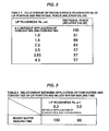
- the test is carried out by sealing the general bearing grease (in which the base oil kinetic viscosity at 40 oC is 65 mm2/s) is sealed into the space between the lips, in a state in which the muddy water (water + loamy powder of the Kanto district JIS8) is dipped into the shaft center of the seal, and turning the slinger at 1000 rpm, and the evaluation is carried out on the basis of the time by which the muddy water intrudes. Results obtained by relatively comparing on the assumption that the muddy water sealing time of the seal to which the concavities and convexities are not applied is 100 will be shown in Table 2 ( Fig. 3 ).
- the sealing performance against the muddy water is equal to that of the seal to which the concavities and convexities are not applied, so that it can be said that it is possible to obtain the low friction effect while maintaining the sealing performance as long as the roughness is equal to or less than 3.0 ⁇ mRa.
Abstract
Description
- The present invention relates to a sealing device, and more particularly to a sealing device having a seal lip which slidably comes into close contact with the other member. The sealing device according to the present invention is used, for example, as a bearing grease seal in an automotive field.
- For example, in a bearing unit of a motor vehicle, a sealing device (hereinafter, refer also to as a seal) is used for the purpose of preventing muddy water from intruding from an external portion and sealing a bearing grease.
- In recent years, it is demanded to make friction low (make torque low) in a target seal as a device for improving a fuel consumption of the motor vehicle. For example, in a prior art shown in
Fig. 5 , there has been proposed a countermeasure achieved by applying concavities and convexities (dimples) 54 to a lip slidable contact surface (a surface of theother member 52 with which aseal lip 51 slidably comes into close contact) 53 (refer to patent document 1). - However, since the
seal lip 51 made of a rubber-like elastic material slides in relation to the concavities andconvexities 54 in the case that the concavities andconvexities 54 are applied to the lipslidable contact surface 53 as mentioned above, a sliding abrasion of theseal lip 51 is promoted, and there is a problem that a deterioration of a sealing performance is caused. - Further, including the
patent document 1 mentioned above, there are the following materials as the prior art documents against the present invention. - However, the inventions described in these documents are all structured such that the concavities and convexities are applied to the lip slidable contact surface (the surface of the other member with which the seal lip slidably comes into close contact) as mentioned above. Accordingly, the inventions are different in structure from the present invention.
-
- Patent Document 1:
WO2006/064908A1 - Patent Document 2:
WO03/091573A1 - Patent Document 3: Japanese Unexamined Patent Publication No.
2008-298106 - Patent Document 4: Japanese Unexamined Patent Publication No.
2010-531966 - The present invention is made by taking the above points into consideration, and an object of the present invention is to provide a sealing device having a seal lip which slidably comes into close contact with the other member, wherein the sealing device can achieve a low friction in conjunction with the sliding motion, and can suppress the lip abrasion.
- In order to achieve the object mentioned above, a sealing device according to a first aspect of the present invention is a sealing device having a seal lip which slidably comes into close contact with the other member, wherein concavities and convexities are applied to a sliding surface of the seal lip and a low base oil viscosity grease is supplied to the sliding surface of the seal lip, for simultaneously achieving a reduction of a frictional force in the sliding motion and a suppression of the lip abrasion.
- Further, a sealing device according to a second aspect of the present invention is the sealing device described in the first aspect mentioned above, wherein the other member is constructed by a slinger which is obtained by integrally forming a flange portion from one end in an axial direction of a tubular portion toward an outer side in a diametrical direction, has a half cut cross sectional surface and is formed approximately as an L-shaped form, the seal lip is provided with a first seal lip which slidably comes into close contact with an end surface of the flange portion, a second seal lip which slidably comes into close contact with an outer peripheral surface of the tubular portion, and a third seal lip which slidably comes into close contact with an outer peripheral surface of the tubular portion in the same manner in an inner side of the second seal lip, the concavities and convexities are applied to each of sliding surfaces of the three seal lips, and the low base oil viscosity grease is filled in each of spaces among the three seal lips.
- Further, a sealing device according to a third aspect of the present invention is the sealing device described in the first or second aspect mentioned above, wherein the concavities and convexities have a magnitude between 1.0 and 3.0 µm Ra.
- Further, a sealing device according to a fourth aspect of the present invention is the sealing device described in the first or second aspect mentioned above, wherein the concavities and convexities have a magnitude between 1.5 and 3.0 µmRa.
- Further, a sealing device according to a fifth aspect of the present invention is the sealing device described in the first, second, third or fourth aspect mentioned above, wherein the low base oil viscosity grease is a grease in which a base oil kinetic viscosity at 40 ºC is between 10 and 40 mm2/s.
- In the sealing device of the present invention having the structure mentioned above, the concavities and convexities are applied to the sliding surface of the seal lip and the low base oil viscosity grease is supplied to the sliding surface of the seal lip. Here, the application of the concavities and convexities means a matter that the concavities and convexities are previously formed, and the supply of the grease means a matter that the grease carries out a lubricating action in the case of the lip sliding action as a result. The concavities and convexities are micro concavities and convexities.
- In the case that the concavities and convexities are applied to the sliding surface of the seal lip, a contact area of the seal lip in relation to the other member is reduced, and the grease easily intervenes by the concavities and convexities. Accordingly, a friction force is reduced. Further, since the low base oil viscosity grease is supplied as the grease, the friction force is further reduced. Further, according to the present invention, since the concavities and convexities are applied to the sliding surface of the seal lip and are not applied to the surface of the other member, the surface of the other member is formed as a smooth surface which is provided with a normal surface roughness. Therefore, since the seal lip made of the rubber-like elastic material does not slide on the concavo-convex surface but slides on the smooth surface, the seal lip is hard to wear by sliding.
- In order to apply the concavities and convexities to the seal lip made of the rubber-like elastic material, it is desirable to form the seal lip by using a metal mold which is processed its surface as concavities and convexities according to a shot blast machining, an electric discharge machining, an emboss machining or a laser beam machining. As a result, it is possible to always provide a stable formed product by appropriately controlling a service life of the metal mold.
- Further, in the sealing device according to the present invention, the other member with which the seal lip slidably comes into close contact is constructed, for example, by the slinger which is obtained by integrally forming the flange portion from the one end in the axial direction of the tubular portion toward the outer side in the diametrical direction, has the half cut cross sectional surface and is formed approximately as the L-shaped form. Further, the seal lip is structured, for example, such as to be provided with the first seal lip which slidably comes into close contact with the end surface of the flange portion in the slinger, the second seal lip which slidably comes into close contact with the outer peripheral surface of the tubular portion, and the third seal lip which slidably comes into close contact with the outer peripheral surface of the tubular portion in the same manner in the inner side of the second seal lip. Further, in these cases, the concavities and convexities are applied to each of the sliding surfaces of the three seal lips, and the low base oil viscosity grease is filled in each of the space between the first seal lip and the second seal lip, and the space between the second seal lip and the third seal lip.
- In the invention described in the
patent document 1 mentioned above, the concavities and convexities applied to the surface of the other member is appropriate in the range of the surface roughness between 0.5 and 1.5 µmRa, however, in the case that the concavities and convexities are applied to the sliding surface of the seal lip in place of the surface of the other member like the present invention, the seal lip tends to be elastically deformed. Accordingly, it is necessary to change the magnitude of the surface roughness. Therefore, as a result of devoting themselves to making a study by the inventors of the present invention, there has been known that it is desirable to make that surface roughness greater than the case mentioned above, that is, between 1.0 and 3.0 µmRa, and set the surface roughness to a range between 1.5 and 3.0 µmRa (corresponding to 10 to 20 µmRz) in the case of taking a practical stage into more consideration, in order to obtain an effect of significantly reducing the frictional force, while maintaining a sealing performance, with regard to the concavities and convexities applied to the sliding surface of the seal lip. - On the other hand, with regard to the grease, particularly in the grease having the low base oil kinetic viscosity, since the grease may be dispersed by the sliding motion, and may cause an increase of a frictional resistance, it is desirable to employ the grease in which the base oil kinetic viscosity at 40 ºC is greater than 10 mm2/s. In the grease (in which the base oil kinetic viscosity at 40 ºC is between 60 and 100 mm2/s) which is used as a grease for a general bearing, the low friction by the roughness of the lip portion can be expected, however, in order to obtain a more significant low friction effect, it is desirable to employ a grease in which the base oil kinetic viscosity at 40 ºC is between 10 and 40 mm2/s.
- The present invention achieves the following effects.
- In other words, in the sealing device of the present invention, as mentioned above, since the concavities and convexities are applied to the sliding surface of the seal lip, the contact area of the seal lip in relation to the other member is reduced, and the grease easily intervenes by the concavities and convexities. Accordingly, the friction force is reduced. Further, since the low base oil viscosity grease is supplied as the grease, the friction force is further reduced. Further, since the concavities and convexities are applied to the sliding surface of the seal lip and are not applied to the surface of the other member, the surface of the other member is formed as the smooth surface which is provided with the normal surface roughness. Therefore, since the seal lip made of the rubber-like elastic material does not slide on the concavo-convex surface but slides on the smooth surface, the seal lip is hard to wear by sliding. As a result, just like the desired purpose of the present invention, it is possible to achieve the low friction in conjunction with the sliding motion in the sealing device having the seal lip which slidably comes into close contact with the other member, and it is possible to provide the sealing device which can suppress the lip abrasion.
-
-
Fig. 1 is a cross sectional view of a substantial part of a sealing device according to an embodiment of the present invention; -
Fig. 2 is a table showing a relationship between a surface roughness Ra of a lip portion and a frictional force (a relative value); -
Fig. 3 is a table showing a relationship between a concavities and convexities application of the lip portion and a muddy water sealing time; -
Fig. 4 is a table showing a relationship between the concavities and convexities application of the lip portion and the frictional force (the relative value) by a low base oil viscosity grease; and -
Fig. 5 is a cross sectional view of a substantial part of a sealing device according to a prior art. -
- 11
- slinger (other member)
- 11a, 22a
- tubular portion
- 11b, 22b
- flange portion
- 11c, 11d
- end surface
- 21
- seal lip member
- 22
- attaching ring
- 23
- rubber-like elastic body
- 24
- attached rubber portion
- 25, 26, 27
- seal lip
- 25a, 26a, 27a
- sliding surface
- 31, 32
- space
- A, B, C
- concavities and convexities applying region
- The following embodiments are included in the present invention.
- (1) The present invention is characterized in that concavities and convexities are applied to a lip portion of a seal and a low base oil viscosity grease is filled, as shown in
Fig. 1 . - (2) The present invention relates to a method of making a torque of a bearing grease seal low, and is characterized by a point that a roughness Ra of a surface of a seal lip portion coming into slidable contact with a slinger is adjusted to Ra = 1.0 to 3.0 µm, and is adjusted to Ra = 1.5 to 3.0 µm in the case of taking into more consideration a practical stage. Further, the torque is further lowered by using the grease having the low base oil viscosity at the same time.
- (3) The present invention is different in its method from the inventions described in the prior art documents, in a point that the surface roughness in the rubber side is adjusted. The low torque can be achieved by enlarging the surface roughness in the rubber lip side, however, since the surface roughness in the metal member side which comes into slidable contact with the rubber lip side is that of the normal finished surface, there is an advantage that the lip does not wear. Further, since the roughness of the lip is formed by finishing the surface of the metal mold into a predetermined surface roughness and transferring the predetermined surface roughness, there is an advantage that a roughness quality can be secured uniformly. Since the surface of the rubber lip is elastically deformed greatly by the slidable contact with the other metal member, an optimum range of the rubber becomes numerical value range which is different from the roughness of the surface which has been conventionally formed in the metal member side. As is apparent from the embodiment according to the present invention, the optimum range can not be easily derived from the inventions described in the prior art documents.
- Next, a description will be given of an embodiment according to the present invention with reference to the accompanying drawings.
-
Fig. 1 shows a cross section of a substantial part of a sealing device according to the embodiment of the present invention. - The sealing device in
Fig. 1 is used as a bearing grease seal in an automotive field, and is constructed by a combination of aslinger 11 which is installed to a bearing inner ring (not shown) and rotates together with the bearing inner ring, and aseal lip member 21 which is installed to a bearing outer ring (not shown) and slidably comes into close contact with theslinger 11. In the invention, the bearing inner ring may be alternatively constructed by a shaft or a sleeve of a rotary equipment, and the bearing outer ring may be alternatively constructed by a housing of the rotary equipment. - The
slinger 11 is made by a metal material, is formed approximately as an L-shaped form in its half cut surface by integrally forming aflange portion 11 b (an outward flange portion) in one end portion in an axial direction of atubular portion 11 a toward an outer side in a diametrical direction, and is fitted to an outer peripheral surface of the bearing inner ring with an inner peripheral surface of thetubular portion 11a. A magnetic encoder may be attached to anouter end surface 11c of theflange portion 11b. - The
seal lip member 21 is constructed by a combination of an attachingring 22, and a rubber-likeelastic body 23 which is attached to the attachingring 22. The attachingring 22 is made of a metal material and is obtained by integrally forming a flange portion (an inward flange portion) 22b in the other end portion in an axial direction of atubular portion 22a toward an inner side in a diametrical direction, and is fitted to an inner peripheral surface of the bearing outer ring with an outer peripheral surface of thetubular portion 22a. The rubber-likeelastic body 23 integrally has an attachedrubber portion 24 which is attached to the attachingring 22, a first seal lip (a side lip) 25 which is supported by the attachedrubber portion 24 and slidably comes into close contact with theinner end surface 11 d of theflange portion 11 b in theslinger 11, a second seal lip (a radial lip) 26 which is supported by the attachedrubber portion 24 in the same manner and slidably comes into close contact with the outer peripheral surface of thetubular portion 11a in theslinger 11, and a third seal lip (a grease lip) 27 which is supported by the attachedrubber portion 24 in the same manner in an inner side (a machine inner side) of thesecond seal lip 26 and slidably comes into close contact with the outer peripheral surface of thetubular portion 11a in theslinger 11. SinceFig. 1 draws free states of theseal lips slinger 11 corresponding to the other member with which theseal lips - Among three
seal lips first seal lip 25 and thesecond seal lip 26 is structured such as to seal so as to prevent the foreign material such as the muddy water in the outer portion of the bearing from intruding into the inner portion of the bearing, and is constructed as an outward lip structure (a structure in which a lip end is directed to the outer portion of the bearing) for the muddy water leakage preventing function. Particularly, thefirst seal lip 25 is formed such that a diameter thereof is gradually enlarged from its base end toward its leading end. Further, thethird seal lip 27 is structured such as to seal so as to prevent the grease in the inner portion of the bearing from leaking out to the outer portion of the bearing, and is constructed as an inward lip structure (a structure in which the lip end is directed to the inner portion of the bearing) for the grease leakage preventing function. - Concavities and convexities (not shown) are applied to each of sliding
surfaces seal lips Fig. 1 , regions to which the concavities and convexities are applied are shown by solid lines A, B and C inFig. 1 . - Further, in the case that three
seal lips slinger 11, a sealedspace 31 is formed between thefirst seal lip 25 and thesecond seal lip 26, and a sealedspace 32 is formed between thesecond seal lip 26 and thethird seal lip 27. In the sealing device, a low base oil viscosity grease (not shown) is filled in each of thespaces - Further, any structure like the concavities and convexities is not applied to the surface of the
slinger 11, that is, the surface of theslinger 11 is finished as a smooth surface which is provided with a normal surface roughness. - In the sealing device having the structure mentioned above, the concavities and convexities are applied to the sliding
surfaces respective seal lips spaces seal lips surfaces respective seal lips surfaces seal lips seal lips slinger 11 are reduced, and the grease tends to intervene by the concavities and convexities. Accordingly, it is possible to reduce the frictional force. Further, since the low base oil viscosity grease is supplied as the grease, it is possible to further reduce the frictional force. - Further, according to the sealing device having the structure mentioned above, since the concavities and convexities are applied to the sliding
surfaces seal lips slinger 11, the surface of theslinger 11 is finished as the smooth surface which is provided with the normal surface roughness. Therefore, since theseal lips seal lips - Accordingly, just like the desired purpose of the present invention, it is possible to achieve the low friction in conjunction with the sliding motion in the sealing device having the seal lip which slidably comes into close contact with the other member, and it is possible to provide the sealing device which can suppress the lip abrasion.
- Next, a description will be given of specifications of respective numeral values.
- An effect of reducing the friction force by applying the concavities and convexities to the seal lip will be shown in Table 1 (
Fig. 2 ). In a state in which a general bearing grease (in which the base oil kinetic viscosity at 40 ºC is 65 mm2/s) is sealed in the space between the lips, and the lip member is fixed to the housing, the frictional force when the slinger is rotated at a rotating speed 500 rpm is measured. Here, the frictional force is relatively compared on the assumption that the friction force in the seal to which the concavities and convexities are not applied is 100. As a result, as shown in Table 1, the greater the surface roughness of the lip is, the more the frictional force is lowered, and the effect of reducing the frictional force is not changed in a range that the surface roughness is greater than 3.0 µmRa (corresponding to 20 µmRz). Since an excessive roughness application on the lip surface causes the reduction of the sealing performance, it is desirable to set the surface roughness of the lip portion to 1.0 to 3.0 µmRa, for obtaining a significant frictional force reducing effect while maintaining the sealing performance, and it is desirable to set the surface roughness to 1.5 to 3.0 µmRa (corresponding to 10 to 20 µmRz) in the case of taking into more consideration the practical stage. - Further, in order to confirm the influence applied to the sealing performance (particularly the sealing performance against the muddy water intrusion from the external portion in the light of the used environment of the seal) by applying the concavities and convexities to the seal lip, an evaluation by the seal to which the concavo-convex process having the surface roughness 3.0 µmRa is applied is executed. The test is carried out by sealing the general bearing grease (in which the base oil kinetic viscosity at 40 ºC is 65 mm2/s) is sealed into the space between the lips, in a state in which the muddy water (water + loamy powder of the Kanto district JIS8) is dipped into the shaft center of the seal, and turning the slinger at 1000 rpm, and the evaluation is carried out on the basis of the time by which the muddy water intrudes. Results obtained by relatively comparing on the assumption that the muddy water sealing time of the seal to which the concavities and convexities are not applied is 100 will be shown in Table 2 (
Fig. 3 ). Even in the seal to which the concavities and convexities having the surface roughness 3.0 µmRa are applied, the sealing performance against the muddy water is equal to that of the seal to which the concavities and convexities are not applied, so that it can be said that it is possible to obtain the low friction effect while maintaining the sealing performance as long as the roughness is equal to or less than 3.0 µmRa. - Subsequently, the effect of reducing the frictional force by applying the concavities and convexities to the seal lip and using the low base oil viscosity grease will be shown in Table 3 (
Fig. 4 ). The test condition is the same as that shown in Table 1, and the friction force of the seal to which the concavities and convexities are not applied while using the grease in which the base oil kinetic viscosity at 40 ºC is 65 mm2/s is assumed to be 100. As a result, it is possible to expect a wider effect of reducing the friction by using the low base oil viscosity grease in addition to the application of the concavities and convexities to the lip. According to the low friction, it is possible to expect an improvement of the fuel consumption on the basis of the reduction of the friction loss and an improvement of a seal service life on the basis of the suppression of the abrasion.
Claims (5)
- A sealing device having a seal lip which slidably comes into close contact with the other member,
wherein concavities and convexities are applied to a sliding surface of said seal lip and a low base oil viscosity grease is supplied to the sliding surface of said seal lip, for simultaneously achieving a reduction of a frictional force in the sliding motion and a suppression of the lip abrasion. - The sealing device according to claim 1, wherein said other member is constructed by a slinger which is obtained by integrally forming a flange portion from one end in an axial direction of a tubular portion toward an outer side in a diametrical direction, has a half cut cross sectional surface and is formed approximately as an L-shaped form,
wherein said seal lip is provided with a first seal lip which slidably comes into close contact with an end surface of said flange portion, a second seal lip which slidably comes into close contact with an outer peripheral surface of said tubular portion, and a third seal lip which slidably comes into close contact with an outer peripheral surface of said tubular portion in the same manner in an inner side of said second seal lip, and
wherein said concavities and convexities are applied to each of sliding surfaces of said three seal lips, and said low base oil viscosity grease is filled in each of spaces among said three seal lips. - The sealing device according to claim 1 or 2, wherein said concavities and convexities have a magnitude between 1.0 and 3.0 µmRa.
- The sealing device according to claim 1 or 2, wherein said concavities and convexities have a magnitude between 1.5 and 3.0 µmRa.
- The sealing device according to claim 1, 2, 3 or 4, wherein said low base oil viscosity grease is a grease in which a base oil kinetic viscosity at 40 ºC is between 10 and 40 mm2/s.
Applications Claiming Priority (2)
| Application Number | Priority Date | Filing Date | Title |
|---|---|---|---|
| JP2011060410A JP5757455B2 (en) | 2011-03-18 | 2011-03-18 | Sealing device |
| PCT/JP2012/051023 WO2012127895A1 (en) | 2011-03-18 | 2012-01-19 | Sealing device |
Publications (3)
| Publication Number | Publication Date |
|---|---|
| EP2687761A1 true EP2687761A1 (en) | 2014-01-22 |
| EP2687761A4 EP2687761A4 (en) | 2015-05-27 |
| EP2687761B1 EP2687761B1 (en) | 2018-01-03 |
Family
ID=46879065
Family Applications (1)
| Application Number | Title | Priority Date | Filing Date |
|---|---|---|---|
| EP12760861.0A Active EP2687761B1 (en) | 2011-03-18 | 2012-01-19 | Sealing device |
Country Status (4)
| Country | Link |
|---|---|
| EP (1) | EP2687761B1 (en) |
| JP (1) | JP5757455B2 (en) |
| CN (2) | CN108286609A (en) |
| WO (1) | WO2012127895A1 (en) |
Cited By (1)
| Publication number | Priority date | Publication date | Assignee | Title |
|---|---|---|---|---|
| WO2022200693A1 (en) | 2021-03-23 | 2022-09-29 | Hutchinson | Seal assembly and rolling bearing comprising such an assembly |
Families Citing this family (14)
| Publication number | Priority date | Publication date | Assignee | Title |
|---|---|---|---|---|
| JP5924239B2 (en) * | 2012-11-09 | 2016-05-25 | 株式会社デンソー | Anti-vibration bush and electronic device |
| CN107429747B (en) * | 2015-03-09 | 2019-11-12 | Ntn株式会社 | Bearing with sealing |
| JP6743378B2 (en) * | 2015-12-02 | 2020-08-19 | Nok株式会社 | Auxiliary seal for sealing device |
| JP6649818B2 (en) * | 2016-03-14 | 2020-02-19 | 光洋シーリングテクノ株式会社 | Sealing member |
| JP2018071604A (en) * | 2016-10-26 | 2018-05-10 | Nok株式会社 | Sealing device |
| JP7049053B2 (en) * | 2016-10-26 | 2022-04-06 | Nok株式会社 | Sealing device |
| JP2018071603A (en) * | 2016-10-26 | 2018-05-10 | Nok株式会社 | Sealing device |
| JP2018084301A (en) * | 2016-11-25 | 2018-05-31 | 内山工業株式会社 | Oil seal and manufacturing method of the same |
| EP3546776B1 (en) | 2016-11-25 | 2021-06-16 | Nok Corporation | Sealing device and hub bearing |
| JP6520976B2 (en) | 2017-03-22 | 2019-05-29 | 株式会社ジェイテクト | Sealed thrust bearing |
| JP7164335B2 (en) * | 2018-07-02 | 2022-11-01 | 光洋シーリングテクノ株式会社 | sealing device |
| CN109505862A (en) * | 2019-01-08 | 2019-03-22 | 湖北新火炬科技有限公司 | A kind of automobile hub bearing of novel sealing |
| JP7251693B2 (en) | 2020-11-20 | 2023-04-04 | 日本精工株式会社 | Grease composition and rolling device |
| JP2022190377A (en) * | 2021-06-14 | 2022-12-26 | Ntn株式会社 | Bearing with seal |
Family Cites Families (21)
| Publication number | Priority date | Publication date | Assignee | Title |
|---|---|---|---|---|
| DE4123392A1 (en) * | 1991-07-15 | 1993-01-21 | Wolf Woco & Co Franz J | Elastomeric sealing ring contg. barrier medium - esp. for sealing aggressive oils on shafts |
| US6186507B1 (en) * | 1997-09-25 | 2001-02-13 | Michael R. Oldenburg | Retrofittable severe duty seal for a shaft |
| JP3656530B2 (en) * | 2000-08-24 | 2005-06-08 | 日本精工株式会社 | Combination seal ring with encoder and rolling bearing unit for wheel support incorporating this |
| WO2003091573A1 (en) | 2002-04-23 | 2003-11-06 | Nsk Ltd. | Seal device for water pump, rotation supporting device for water pump, and assembly method for water pump |
| JP3793746B2 (en) * | 2002-07-02 | 2006-07-05 | 株式会社ジェイテクト | Sliding member and sealing device |
| JP4243698B2 (en) * | 2003-03-17 | 2009-03-25 | Nok株式会社 | Sealing device |
| CN2752528Y (en) * | 2004-06-15 | 2006-01-18 | 万向钱潮股份有限公司 | Wheel hub bearing unit sealing structure |
| CN1985114B (en) * | 2004-07-16 | 2010-12-08 | Nok株式会社 | Sealing device |
| EP3101292A3 (en) * | 2004-12-16 | 2017-02-22 | Uchiyama Manufacturing Corp. | Seal structure of a rotation member |
| JP2008057756A (en) * | 2006-09-04 | 2008-03-13 | Kayaba Ind Co Ltd | Oil seal for reciprocating |
| JP2008069882A (en) * | 2006-09-14 | 2008-03-27 | Ntn Corp | Grease-filled sealing type rolling bearing |
| JP5041137B2 (en) * | 2007-01-29 | 2012-10-03 | Nok株式会社 | Sealing device |
| JP5168453B2 (en) * | 2007-03-30 | 2013-03-21 | Nok株式会社 | Sealing device |
| JP4371429B2 (en) | 2007-05-29 | 2009-11-25 | Ntn株式会社 | Wheel bearing device |
| FR2918135B1 (en) | 2007-06-29 | 2009-09-04 | Snr Roulements Sa | BEARING BEARING AND SEAL WITH IMPROVED DYNAMIC BEHAVIOR. |
| JP2009041708A (en) * | 2007-08-10 | 2009-02-26 | Nok Corp | Sealing device |
| WO2009103314A1 (en) * | 2008-02-20 | 2009-08-27 | Carl Freudenberg Kg | Sealing arrangement and radial shaft seal made therefrom |
| US8702312B2 (en) * | 2008-05-27 | 2014-04-22 | Nsk Ltd. | Rolling bearing |
| JP5234651B2 (en) * | 2008-08-29 | 2013-07-10 | 内山工業株式会社 | Sealing device |
| CN201475175U (en) * | 2009-05-12 | 2010-05-19 | 浙江万向精工有限公司 | Sealing structure of hub bearing unit |
| EP2290269B1 (en) * | 2009-08-26 | 2016-07-06 | Carl Freudenberg KG | Seal |
-
2011
- 2011-03-18 JP JP2011060410A patent/JP5757455B2/en active Active
-
2012
- 2012-01-19 CN CN201810171228.5A patent/CN108286609A/en active Pending
- 2012-01-19 CN CN2012800134378A patent/CN103459902A/en active Pending
- 2012-01-19 EP EP12760861.0A patent/EP2687761B1/en active Active
- 2012-01-19 WO PCT/JP2012/051023 patent/WO2012127895A1/en unknown
Cited By (1)
| Publication number | Priority date | Publication date | Assignee | Title |
|---|---|---|---|---|
| WO2022200693A1 (en) | 2021-03-23 | 2022-09-29 | Hutchinson | Seal assembly and rolling bearing comprising such an assembly |
Also Published As
| Publication number | Publication date |
|---|---|
| CN108286609A (en) | 2018-07-17 |
| WO2012127895A1 (en) | 2012-09-27 |
| CN103459902A (en) | 2013-12-18 |
| EP2687761A4 (en) | 2015-05-27 |
| JP5757455B2 (en) | 2015-07-29 |
| JP2012193835A (en) | 2012-10-11 |
| EP2687761B1 (en) | 2018-01-03 |
Similar Documents
| Publication | Publication Date | Title |
|---|---|---|
| EP2687761B1 (en) | Sealing device | |
| JP6523994B2 (en) | Sealed bearing | |
| EP2881631B1 (en) | Sealing device | |
| EP2990698A1 (en) | Low-friction dynamic seal | |
| US11215284B2 (en) | Sealing apparatus | |
| EP2821661B1 (en) | Sealing device | |
| WO2014024741A1 (en) | Sliding component | |
| CN103238012B (en) | Seal arrangement and sealing configuration | |
| JP2018040445A (en) | Bearing with seal | |
| JP6378548B2 (en) | Sealing device | |
| EP3819526B1 (en) | Sealing device | |
| JP6566384B2 (en) | Sealing device | |
| JP2018084318A (en) | Sealing device and sealing structure | |
| WO2020255591A1 (en) | Sealing device | |
| KR102213573B1 (en) | Sealing device and sealing structure | |
| JP2017180739A (en) | Bearing with seal | |
| EP3273118B1 (en) | Sealing device | |
| WO2022181437A1 (en) | Seal-attached bearing | |
| JP6628207B2 (en) | Sealing device | |
| JP6853367B2 (en) | Sealing device | |
| JP7331053B2 (en) | Sealed bearing | |
| KR102363628B1 (en) | Surface processing method and sealing device of the disk member of the sealing device | |
| WO2022264910A1 (en) | Sealed bearing | |
| JP2016205564A (en) | Sealed rolling bearing | |
| JP2024511314A (en) | Seal assemblies and rolling bearings with such assemblies |
Legal Events
| Date | Code | Title | Description |
|---|---|---|---|
| PUAI | Public reference made under article 153(3) epc to a published international application that has entered the european phase |
Free format text: ORIGINAL CODE: 0009012 |
|
| 17P | Request for examination filed |
Effective date: 20130917 |
|
| AK | Designated contracting states |
Kind code of ref document: A1 Designated state(s): AL AT BE BG CH CY CZ DE DK EE ES FI FR GB GR HR HU IE IS IT LI LT LU LV MC MK MT NL NO PL PT RO RS SE SI SK SM TR |
|
| DAX | Request for extension of the european patent (deleted) | ||
| RA4 | Supplementary search report drawn up and despatched (corrected) |
Effective date: 20150423 |
|
| RIC1 | Information provided on ipc code assigned before grant |
Ipc: C10M 171/02 20060101ALI20150417BHEP Ipc: F16C 19/18 20060101ALI20150417BHEP Ipc: F16J 15/32 20060101AFI20150417BHEP Ipc: C10N 50/10 20060101ALI20150417BHEP Ipc: C10N 20/02 20060101ALI20150417BHEP Ipc: F16C 33/78 20060101ALI20150417BHEP Ipc: C10N 30/06 20060101ALI20150417BHEP Ipc: C10N 40/02 20060101ALI20150417BHEP |
|
| 17Q | First examination report despatched |
Effective date: 20160520 |
|
| REG | Reference to a national code |
Ref country code: DE Ref legal event code: R079 Ref document number: 602012041607 Country of ref document: DE Free format text: PREVIOUS MAIN CLASS: F16J0015320000 Ipc: F16J0015324000 |
|
| RIC1 | Information provided on ipc code assigned before grant |
Ipc: F16J 15/3264 20160101ALI20170620BHEP Ipc: F16C 33/78 20060101ALI20170620BHEP Ipc: C10M 171/02 20060101ALI20170620BHEP Ipc: F16J 15/324 20160101AFI20170620BHEP |
|
| GRAP | Despatch of communication of intention to grant a patent |
Free format text: ORIGINAL CODE: EPIDOSNIGR1 |
|
| INTG | Intention to grant announced |
Effective date: 20170803 |
|
| GRAS | Grant fee paid |
Free format text: ORIGINAL CODE: EPIDOSNIGR3 |
|
| GRAA | (expected) grant |
Free format text: ORIGINAL CODE: 0009210 |
|
| AK | Designated contracting states |
Kind code of ref document: B1 Designated state(s): AL AT BE BG CH CY CZ DE DK EE ES FI FR GB GR HR HU IE IS IT LI LT LU LV MC MK MT NL NO PL PT RO RS SE SI SK SM TR |
|
| REG | Reference to a national code |
Ref country code: GB Ref legal event code: FG4D |
|
| REG | Reference to a national code |
Ref country code: CH Ref legal event code: EP Ref country code: AT Ref legal event code: REF Ref document number: 960596 Country of ref document: AT Kind code of ref document: T Effective date: 20180115 |
|
| REG | Reference to a national code |
Ref country code: IE Ref legal event code: FG4D |
|
| REG | Reference to a national code |
Ref country code: DE Ref legal event code: R096 Ref document number: 602012041607 Country of ref document: DE |
|
| REG | Reference to a national code |
Ref country code: FR Ref legal event code: PLFP Year of fee payment: 7 |
|
| REG | Reference to a national code |
Ref country code: NL Ref legal event code: MP Effective date: 20180103 |
|
| REG | Reference to a national code |
Ref country code: LT Ref legal event code: MG4D |
|
| REG | Reference to a national code |
Ref country code: AT Ref legal event code: MK05 Ref document number: 960596 Country of ref document: AT Kind code of ref document: T Effective date: 20180103 |
|
| PG25 | Lapsed in a contracting state [announced via postgrant information from national office to epo] |
Ref country code: NL Free format text: LAPSE BECAUSE OF FAILURE TO SUBMIT A TRANSLATION OF THE DESCRIPTION OR TO PAY THE FEE WITHIN THE PRESCRIBED TIME-LIMIT Effective date: 20180103 |
|
| PG25 | Lapsed in a contracting state [announced via postgrant information from national office to epo] |
Ref country code: NO Free format text: LAPSE BECAUSE OF FAILURE TO SUBMIT A TRANSLATION OF THE DESCRIPTION OR TO PAY THE FEE WITHIN THE PRESCRIBED TIME-LIMIT Effective date: 20180403 Ref country code: FI Free format text: LAPSE BECAUSE OF FAILURE TO SUBMIT A TRANSLATION OF THE DESCRIPTION OR TO PAY THE FEE WITHIN THE PRESCRIBED TIME-LIMIT Effective date: 20180103 Ref country code: HR Free format text: LAPSE BECAUSE OF FAILURE TO SUBMIT A TRANSLATION OF THE DESCRIPTION OR TO PAY THE FEE WITHIN THE PRESCRIBED TIME-LIMIT Effective date: 20180103 Ref country code: CY Free format text: LAPSE BECAUSE OF FAILURE TO SUBMIT A TRANSLATION OF THE DESCRIPTION OR TO PAY THE FEE WITHIN THE PRESCRIBED TIME-LIMIT Effective date: 20180103 Ref country code: ES Free format text: LAPSE BECAUSE OF FAILURE TO SUBMIT A TRANSLATION OF THE DESCRIPTION OR TO PAY THE FEE WITHIN THE PRESCRIBED TIME-LIMIT Effective date: 20180103 Ref country code: LT Free format text: LAPSE BECAUSE OF FAILURE TO SUBMIT A TRANSLATION OF THE DESCRIPTION OR TO PAY THE FEE WITHIN THE PRESCRIBED TIME-LIMIT Effective date: 20180103 |
|
| PG25 | Lapsed in a contracting state [announced via postgrant information from national office to epo] |
Ref country code: GR Free format text: LAPSE BECAUSE OF FAILURE TO SUBMIT A TRANSLATION OF THE DESCRIPTION OR TO PAY THE FEE WITHIN THE PRESCRIBED TIME-LIMIT Effective date: 20180404 Ref country code: BG Free format text: LAPSE BECAUSE OF FAILURE TO SUBMIT A TRANSLATION OF THE DESCRIPTION OR TO PAY THE FEE WITHIN THE PRESCRIBED TIME-LIMIT Effective date: 20180403 Ref country code: RS Free format text: LAPSE BECAUSE OF FAILURE TO SUBMIT A TRANSLATION OF THE DESCRIPTION OR TO PAY THE FEE WITHIN THE PRESCRIBED TIME-LIMIT Effective date: 20180103 Ref country code: IS Free format text: LAPSE BECAUSE OF FAILURE TO SUBMIT A TRANSLATION OF THE DESCRIPTION OR TO PAY THE FEE WITHIN THE PRESCRIBED TIME-LIMIT Effective date: 20180503 Ref country code: LV Free format text: LAPSE BECAUSE OF FAILURE TO SUBMIT A TRANSLATION OF THE DESCRIPTION OR TO PAY THE FEE WITHIN THE PRESCRIBED TIME-LIMIT Effective date: 20180103 Ref country code: SE Free format text: LAPSE BECAUSE OF FAILURE TO SUBMIT A TRANSLATION OF THE DESCRIPTION OR TO PAY THE FEE WITHIN THE PRESCRIBED TIME-LIMIT Effective date: 20180103 Ref country code: AT Free format text: LAPSE BECAUSE OF FAILURE TO SUBMIT A TRANSLATION OF THE DESCRIPTION OR TO PAY THE FEE WITHIN THE PRESCRIBED TIME-LIMIT Effective date: 20180103 Ref country code: PL Free format text: LAPSE BECAUSE OF FAILURE TO SUBMIT A TRANSLATION OF THE DESCRIPTION OR TO PAY THE FEE WITHIN THE PRESCRIBED TIME-LIMIT Effective date: 20180103 |
|
| REG | Reference to a national code |
Ref country code: CH Ref legal event code: PL |
|
| REG | Reference to a national code |
Ref country code: DE Ref legal event code: R097 Ref document number: 602012041607 Country of ref document: DE |
|
| PG25 | Lapsed in a contracting state [announced via postgrant information from national office to epo] |
Ref country code: EE Free format text: LAPSE BECAUSE OF FAILURE TO SUBMIT A TRANSLATION OF THE DESCRIPTION OR TO PAY THE FEE WITHIN THE PRESCRIBED TIME-LIMIT Effective date: 20180103 Ref country code: LU Free format text: LAPSE BECAUSE OF NON-PAYMENT OF DUE FEES Effective date: 20180119 Ref country code: IT Free format text: LAPSE BECAUSE OF FAILURE TO SUBMIT A TRANSLATION OF THE DESCRIPTION OR TO PAY THE FEE WITHIN THE PRESCRIBED TIME-LIMIT Effective date: 20180103 Ref country code: RO Free format text: LAPSE BECAUSE OF FAILURE TO SUBMIT A TRANSLATION OF THE DESCRIPTION OR TO PAY THE FEE WITHIN THE PRESCRIBED TIME-LIMIT Effective date: 20180103 Ref country code: AL Free format text: LAPSE BECAUSE OF FAILURE TO SUBMIT A TRANSLATION OF THE DESCRIPTION OR TO PAY THE FEE WITHIN THE PRESCRIBED TIME-LIMIT Effective date: 20180103 Ref country code: MC Free format text: LAPSE BECAUSE OF FAILURE TO SUBMIT A TRANSLATION OF THE DESCRIPTION OR TO PAY THE FEE WITHIN THE PRESCRIBED TIME-LIMIT Effective date: 20180103 |
|
| REG | Reference to a national code |
Ref country code: IE Ref legal event code: MM4A |
|
| REG | Reference to a national code |
Ref country code: BE Ref legal event code: MM Effective date: 20180131 |
|
| PLBE | No opposition filed within time limit |
Free format text: ORIGINAL CODE: 0009261 |
|
| STAA | Information on the status of an ep patent application or granted ep patent |
Free format text: STATUS: NO OPPOSITION FILED WITHIN TIME LIMIT |
|
| PG25 | Lapsed in a contracting state [announced via postgrant information from national office to epo] |
Ref country code: BE Free format text: LAPSE BECAUSE OF NON-PAYMENT OF DUE FEES Effective date: 20180131 Ref country code: SK Free format text: LAPSE BECAUSE OF FAILURE TO SUBMIT A TRANSLATION OF THE DESCRIPTION OR TO PAY THE FEE WITHIN THE PRESCRIBED TIME-LIMIT Effective date: 20180103 Ref country code: SM Free format text: LAPSE BECAUSE OF FAILURE TO SUBMIT A TRANSLATION OF THE DESCRIPTION OR TO PAY THE FEE WITHIN THE PRESCRIBED TIME-LIMIT Effective date: 20180103 Ref country code: LI Free format text: LAPSE BECAUSE OF NON-PAYMENT OF DUE FEES Effective date: 20180131 Ref country code: DK Free format text: LAPSE BECAUSE OF FAILURE TO SUBMIT A TRANSLATION OF THE DESCRIPTION OR TO PAY THE FEE WITHIN THE PRESCRIBED TIME-LIMIT Effective date: 20180103 Ref country code: CZ Free format text: LAPSE BECAUSE OF FAILURE TO SUBMIT A TRANSLATION OF THE DESCRIPTION OR TO PAY THE FEE WITHIN THE PRESCRIBED TIME-LIMIT Effective date: 20180103 Ref country code: CH Free format text: LAPSE BECAUSE OF NON-PAYMENT OF DUE FEES Effective date: 20180131 |
|
| 26N | No opposition filed |
Effective date: 20181005 |
|
| PG25 | Lapsed in a contracting state [announced via postgrant information from national office to epo] |
Ref country code: IE Free format text: LAPSE BECAUSE OF NON-PAYMENT OF DUE FEES Effective date: 20180119 |
|
| PG25 | Lapsed in a contracting state [announced via postgrant information from national office to epo] |
Ref country code: SI Free format text: LAPSE BECAUSE OF FAILURE TO SUBMIT A TRANSLATION OF THE DESCRIPTION OR TO PAY THE FEE WITHIN THE PRESCRIBED TIME-LIMIT Effective date: 20180103 |
|
| PG25 | Lapsed in a contracting state [announced via postgrant information from national office to epo] |
Ref country code: MT Free format text: LAPSE BECAUSE OF NON-PAYMENT OF DUE FEES Effective date: 20180119 |
|
| PG25 | Lapsed in a contracting state [announced via postgrant information from national office to epo] |
Ref country code: TR Free format text: LAPSE BECAUSE OF FAILURE TO SUBMIT A TRANSLATION OF THE DESCRIPTION OR TO PAY THE FEE WITHIN THE PRESCRIBED TIME-LIMIT Effective date: 20180103 |
|
| PG25 | Lapsed in a contracting state [announced via postgrant information from national office to epo] |
Ref country code: HU Free format text: LAPSE BECAUSE OF FAILURE TO SUBMIT A TRANSLATION OF THE DESCRIPTION OR TO PAY THE FEE WITHIN THE PRESCRIBED TIME-LIMIT; INVALID AB INITIO Effective date: 20120119 Ref country code: PT Free format text: LAPSE BECAUSE OF FAILURE TO SUBMIT A TRANSLATION OF THE DESCRIPTION OR TO PAY THE FEE WITHIN THE PRESCRIBED TIME-LIMIT Effective date: 20180103 |
|
| PG25 | Lapsed in a contracting state [announced via postgrant information from national office to epo] |
Ref country code: MK Free format text: LAPSE BECAUSE OF NON-PAYMENT OF DUE FEES Effective date: 20180103 |
|
| PGFP | Annual fee paid to national office [announced via postgrant information from national office to epo] |
Ref country code: DE Payment date: 20221130 Year of fee payment: 12 |
|
| PGFP | Annual fee paid to national office [announced via postgrant information from national office to epo] |
Ref country code: GB Payment date: 20231130 Year of fee payment: 13 |
|
| PGFP | Annual fee paid to national office [announced via postgrant information from national office to epo] |
Ref country code: FR Payment date: 20231212 Year of fee payment: 13 |