EP2687752A1 - Friction roller type deceleration device and drive device for electric automobile - Google Patents
Friction roller type deceleration device and drive device for electric automobile Download PDFInfo
- Publication number
- EP2687752A1 EP2687752A1 EP12757168.5A EP12757168A EP2687752A1 EP 2687752 A1 EP2687752 A1 EP 2687752A1 EP 12757168 A EP12757168 A EP 12757168A EP 2687752 A1 EP2687752 A1 EP 2687752A1
- Authority
- EP
- European Patent Office
- Prior art keywords
- roller
- section
- sections
- ring
- pivot
- Prior art date
- Legal status (The legal status is an assumption and is not a legal conclusion. Google has not performed a legal analysis and makes no representation as to the accuracy of the status listed.)
- Granted
Links
- 239000003638 chemical reducing agent Substances 0.000 claims abstract description 109
- 230000005540 biological transmission Effects 0.000 claims abstract description 72
- 238000006073 displacement reaction Methods 0.000 claims abstract description 35
- 238000005096 rolling process Methods 0.000 claims description 45
- 230000007246 mechanism Effects 0.000 claims description 34
- 230000009467 reduction Effects 0.000 claims description 7
- 238000003825 pressing Methods 0.000 claims description 3
- 230000001419 dependent effect Effects 0.000 claims 1
- 238000010276 construction Methods 0.000 abstract description 79
- 230000008859 change Effects 0.000 abstract description 5
- 230000006835 compression Effects 0.000 description 14
- 238000007906 compression Methods 0.000 description 14
- 230000001133 acceleration Effects 0.000 description 7
- 238000010586 diagram Methods 0.000 description 5
- 230000033001 locomotion Effects 0.000 description 5
- 230000001771 impaired effect Effects 0.000 description 4
- 230000036316 preload Effects 0.000 description 4
- 230000001105 regulatory effect Effects 0.000 description 4
- 230000007423 decrease Effects 0.000 description 3
- 230000005484 gravity Effects 0.000 description 3
- 239000007769 metal material Substances 0.000 description 3
- 238000005520 cutting process Methods 0.000 description 2
- 230000006872 improvement Effects 0.000 description 2
- 230000007935 neutral effect Effects 0.000 description 2
- 230000004044 response Effects 0.000 description 2
- 238000005266 casting Methods 0.000 description 1
- 230000000694 effects Effects 0.000 description 1
- 238000005516 engineering process Methods 0.000 description 1
- 239000004519 grease Substances 0.000 description 1
- 230000001788 irregular Effects 0.000 description 1
- 239000000314 lubricant Substances 0.000 description 1
- 238000005461 lubrication Methods 0.000 description 1
- 238000004519 manufacturing process Methods 0.000 description 1
- 238000005058 metal casting Methods 0.000 description 1
- 238000005192 partition Methods 0.000 description 1
- 230000003746 surface roughness Effects 0.000 description 1
- 239000010409 thin film Substances 0.000 description 1
Images

















Classifications
-
- F—MECHANICAL ENGINEERING; LIGHTING; HEATING; WEAPONS; BLASTING
- F16—ENGINEERING ELEMENTS AND UNITS; GENERAL MEASURES FOR PRODUCING AND MAINTAINING EFFECTIVE FUNCTIONING OF MACHINES OR INSTALLATIONS; THERMAL INSULATION IN GENERAL
- F16H—GEARING
- F16H13/00—Gearing for conveying rotary motion with constant gear ratio by friction between rotary members
- F16H13/06—Gearing for conveying rotary motion with constant gear ratio by friction between rotary members with members having orbital motion
- F16H13/08—Gearing for conveying rotary motion with constant gear ratio by friction between rotary members with members having orbital motion with balls or with rollers acting in a similar manner
-
- F—MECHANICAL ENGINEERING; LIGHTING; HEATING; WEAPONS; BLASTING
- F16—ENGINEERING ELEMENTS AND UNITS; GENERAL MEASURES FOR PRODUCING AND MAINTAINING EFFECTIVE FUNCTIONING OF MACHINES OR INSTALLATIONS; THERMAL INSULATION IN GENERAL
- F16H—GEARING
- F16H13/00—Gearing for conveying rotary motion with constant gear ratio by friction between rotary members
- F16H13/06—Gearing for conveying rotary motion with constant gear ratio by friction between rotary members with members having orbital motion
-
- F—MECHANICAL ENGINEERING; LIGHTING; HEATING; WEAPONS; BLASTING
- F16—ENGINEERING ELEMENTS AND UNITS; GENERAL MEASURES FOR PRODUCING AND MAINTAINING EFFECTIVE FUNCTIONING OF MACHINES OR INSTALLATIONS; THERMAL INSULATION IN GENERAL
- F16H—GEARING
- F16H13/00—Gearing for conveying rotary motion with constant gear ratio by friction between rotary members
- F16H13/10—Means for influencing the pressure between the members
-
- F—MECHANICAL ENGINEERING; LIGHTING; HEATING; WEAPONS; BLASTING
- F16—ENGINEERING ELEMENTS AND UNITS; GENERAL MEASURES FOR PRODUCING AND MAINTAINING EFFECTIVE FUNCTIONING OF MACHINES OR INSTALLATIONS; THERMAL INSULATION IN GENERAL
- F16H—GEARING
- F16H13/00—Gearing for conveying rotary motion with constant gear ratio by friction between rotary members
- F16H13/10—Means for influencing the pressure between the members
- F16H13/14—Means for influencing the pressure between the members for automatically varying the pressure mechanically
-
- H—ELECTRICITY
- H02—GENERATION; CONVERSION OR DISTRIBUTION OF ELECTRIC POWER
- H02K—DYNAMO-ELECTRIC MACHINES
- H02K7/00—Arrangements for handling mechanical energy structurally associated with dynamo-electric machines, e.g. structural association with mechanical driving motors or auxiliary dynamo-electric machines
- H02K7/10—Structural association with clutches, brakes, gears, pulleys or mechanical starters
- H02K7/116—Structural association with clutches, brakes, gears, pulleys or mechanical starters with gears
-
- F—MECHANICAL ENGINEERING; LIGHTING; HEATING; WEAPONS; BLASTING
- F16—ENGINEERING ELEMENTS AND UNITS; GENERAL MEASURES FOR PRODUCING AND MAINTAINING EFFECTIVE FUNCTIONING OF MACHINES OR INSTALLATIONS; THERMAL INSULATION IN GENERAL
- F16H—GEARING
- F16H2200/00—Transmissions for multiple ratios
- F16H2200/0021—Transmissions for multiple ratios specially adapted for electric vehicles
-
- Y—GENERAL TAGGING OF NEW TECHNOLOGICAL DEVELOPMENTS; GENERAL TAGGING OF CROSS-SECTIONAL TECHNOLOGIES SPANNING OVER SEVERAL SECTIONS OF THE IPC; TECHNICAL SUBJECTS COVERED BY FORMER USPC CROSS-REFERENCE ART COLLECTIONS [XRACs] AND DIGESTS
- Y02—TECHNOLOGIES OR APPLICATIONS FOR MITIGATION OR ADAPTATION AGAINST CLIMATE CHANGE
- Y02T—CLIMATE CHANGE MITIGATION TECHNOLOGIES RELATED TO TRANSPORTATION
- Y02T10/00—Road transport of goods or passengers
- Y02T10/60—Other road transportation technologies with climate change mitigation effect
- Y02T10/64—Electric machine technologies in electromobility
Definitions
- the present invention relates to a friction roller reducer for transmitting torque from an electric motor to driven wheels when assembled in the drive system of an electric automobile for example, and to a drive unit for an electric automobile in which this friction roller reducer is assembled.
- Friction roller reducers that can be used for this purpose are known and disclosed in JP 59-187154 A , JP 61-136053 A , and JP 2004-116670 A . Of these, conventional construction as disclosed in JP 2004-116670 A will be explained using FIG. 51 to FIG. 53 .
- the ring-shaped roller 5 is overall ring shaped, and is supported by and fastened to a stationary portion such as a housing (not illustrated in the figure) so as to be arranged around the sun roller 4 and so as to be concentric with the sun roller 4.
- the inner circumferential surface of the ring-shaped roller 5 functions as a rolling contact surface and is inclined in a direction such that the inner diameter becomes larger going toward the center section in the axial direction.
- the plurality of planet rollers 6 are arranged at a plurality of locations in the circumferential direction of a ring-shaped space 9 between the outer circumferential surface of the sun roller 4 and the inner circumferential surface of the ring-shaped roller 5.
- the planet rollers 6 are arranged so as to be parallel with the input shaft 2 and the output shaft 3, and each is supported around a planet shaft 10, which is a rotating shaft, by way of radial needle bearing so as to be able to rotate freely.
- the end sections of these planet shafts 10 and supported by and fastened to a carrier 11, which is a support frame, that is connected and fastened to the base end section of the output shaft 3.
- the outer circumferential surface of the planet rollers 6 is a convex curved surface having a generating line that is a partial arc shape, and each comes in rolling contact with the outer circumferential surface of the sun roller 4 and the inner circumferential surface of the ring-shaped roller 5.
- this kind of loading cam 7 is such that when the input shaft 2 is stopped, the ball 16 is located in the deepest portion of the driven-side cam surface 17 and the driving-side cam surface 18. In this state, the elastic force of the disc spring 14 presses the one sun roller element 8a toward the other sun roller element 8b.
- FIG. 53B as the input shaft 2 rotates, the ball 16 moves to the portion of the cam surfaces 17, 18 that are shallow. The space between the sun roller element 8a and cam plate 15 is opened up, and the sun roller element 8a is pressed toward the sun roller element 8b. As a result, the sun roller element 8a is rotated and driven while being pressed toward the sun roller element 8b with the larger force of the elastic force of the disc spring 14 and the thrust force that is generated by the ball 16 riding up on the cam surfaces 17, 18.
- the space between the sun roller elements 8a, 8b is reduced by the thrust force in the axial direction that is generated by the loading cam apparatus 7.
- the surface pressure at the rolling contact sections between the outer circumferential surface of the sun roller 4 that is constructed by these sun roller elements 8a, 8b and the outer circumferential surfaces of the planet rollers 6 increases.
- the planet rollers 6 are pressed outward in the radial direction of the sun roller 4 and ring-shaped roller 5.
- the surface pressure at the rolling contact areas between the inner circumferential surface of the ring-shaped roller 5 and the outer circumferential surface of the planet gears 6 also increases.
- the surface pressure at a plurality of rolling contact areas between the input shaft 2 and output shaft 3, which are traction sections for transmitting power increases according to the size of the torque to be transmitted between the input shaft 2 and the output shaft 3.
- the planet rollers 6 displace a small amount (for example a maximum of several hundred ⁇ m) in the radial direction of the sun roller 4 and ring-shaped roller 5 due to the movement of the loading cam apparatus 7.
- the dimension in the axial direction of the loading cam apparatus 7 changes (expands or contracts), and the dimension on the radial direction of the portion of the one sun roller element 8a that has entered on the inside of the planet roller 6 changes. Due to this change, the planet rollers 6 displace in the radial direction of the sun roller 4 and the ring-shaped roller 5, however, in the construction illustrated in FIG.
- JP 2004-52729 A construction that increases the operation response is disclosed in JP 2004-52729 A wherein in an apparatus in which the tip end section of a link is caused to engage with the groove in the radial direction of a drive ring and in a coil shaped groove of an intermediate rotating member, and the base end section of the link is connected to a lever of a driven shaft member, and a rotation operating force that is applied to the intermediate rotating member is converted to relative rotation between the drive ring and driven shaft member by way of the link, a weight adding section is provided in the link such that the centrifugal force due to the rotation of the apparatus does not act as a large moment on the link.
- the sun roller comprises a pair of sun roller elements that are separated in the axial direction and located around an input shaft, so that when there is a space between the tip end surfaces of each, each is concentric and is capable of relative rotating with respect to the input shaft.
- each of the sun roller elements has an outer circumferential surface, which is a rolling contact surface, that has an inclined surface that is inclined in a direction such that the outer diameter thereof becomes smaller going toward the respective tip end surface.
- the ring-shaped roller is located around the outside of the sun roller so as to be concentric with the sun roller, and has an inner circumferential surface, which is a rolling contact surface.
- a plurality of intermediate rollers are supported at a plurality of locations in the circumferential direction of a ring-shaped space between the outer circumferential surface of the sun roller and the inner circumferential surface of the ring-shaped roller so as to be able to rotate freely around rotation shafts that are arranged parallel with the input shaft, and each intermediate roller has an outer circumferential surface that comes in rolling contact with the outer circumferential surface of the sun roller and the inner circumferential surface of the ring-shaped roller.
- the loading cam apparatus is provided between at least one movable sun roller element of the sun roller elements and the input shaft, and as the input shaft rotates, causes the movable sun roller element to rotate while pressing the movable sun roller element in the axial direction toward the other sun roller element.
- the loading cam apparatus has: driven-side cam surfaces that are provided at a plurality of locations in the circumferential direction of the base end surface of the movable sun roller element, and each is shaped such that the depth in the axial direction thereof gradually changes in the circumferential direction and becomes more shallow going toward the end section; driving-side cam surfaces that are provided at a plurality of locations in the circumferential direction of the surface on one side of a cam plate that faces the base end surface of the movable sun roller element, and each is shaped such that the depth in the axial direction thereof gradually changes in the circumferential direction and becomes more shallow going toward the end section; and a plurality of rolling bodies that are held between the each of the driven-side cam surfaces and the driving-side cam surfaces.
- construction can be employed wherein the member that supports the rotation shafts is stationary and does not rotate, and the intermediate rollers only rotate around the respective rotation shafts that are provided on the member that supports the rotation shafts, and transmit torque from the sun roller to the ring-shaped roller, and this ring-shaped roller is concentrically connected with the output shaft and rotates together with the output shaft.
- construction can be employed wherein the ring-shaped roller is stationary and does not rotate, and the member that supports the rotation shafts rotates; the intermediate rollers are planet rollers that revolve around the sun roller together with the member that supports the rotation shafts while also rotating around the respective rotation shafts that are provided on the member that supports the rotation shafts; and the member that supports the rotation shafts is concentrically connected to the output shaft, and rotates together with the output shaft.
- the pivot mechanism supports is constructed by: a plurality of pivot frames that supports the intermediate rollers so as to be able rotate freely around the respective rotation shafts, and a support frame that supports these pivot frames so as to be able to displace in the radial direction of the sun roller and the ring-shaped roller.
- the pivot frames are supported by the support frame so as to be able to pivotally displace around each of a plurality of pivot shafts that are parallel with the rotation shafts and that are located on the support frame such that the phase of the pivot shafts in the direction of rotation of the sun roller is separated from the rotation shafts; and these pivot frames support the rotation shafts so as to be able to displace in the radial direction of the sun roller and the ring-shaped roller.
- the rotation shafts are constructed by bolts each having: a circular column section in the middle section in the axial direction, a male screw section on the tip end section having a diameter that is smaller than the circular column section, and a head section on the base end section having a diameter that is larger than the circular column section.
- a through hole having a smaller diameter than the head section is formed in one of the tip end sections of each pair of support arms of the pivot frames, and a screw hole in which the male screw section can be screwed is formed in the other tip end section so as to be concentric with the through hole; and by inserting the circular column section through the through hole and screwing the male screw section in the screw hole, the rotation shaft is supported and fastened between the pair of support arms, and the space between the pair of support arms is prevented from expanding.
- construction can be employed wherein a counterweight section is provided on the opposite side from the tip end section of the base section, and as the intermediate roller revolves, a force outward in the radial direction of the support frame that is applied to the planet roller due to a centrifugal force is reduced or cancelled out by the centrifugal force that is applied to the counterweight section.
- each of the pivot frames can be formed by connecting and fastening together by way of connecting sections both ends in the lengthwise direction of a pair of support plate sections that are separated in the axial direction, and supports both end sections of the rotation shaft between the middle sections in the lengthwise direction of these support plate sections.
- the structure can be adopted where the support frame comprises concave support sections at a plurality of locations in the circumferential direction of the surface on one side in the axial direction; each pivot frame is formed by connecting and fastening together by way of connecting section both ends in the lengthwise direction of a pair of support plate sections that are separated in the axial direction; both end sections of the rotation shaft are supported between the middle sections in the lengthwise direction of these support plate sections; and the pivot frames is supported inside each of the concave support section so as to be able to pivotally displace around the area of contact between the outside surface of one end section in the lengthwise direction of each of the pivot frames and an inside surface of each of the concave support sections.
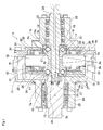
- FIG. 1 to FIG. 8 illustrate a first example of an embodiment of the present invention.
- the friction roller reducer 1a of this example is such that an input shaft 2a rotates and drives a sun roller 4a, the rotation of this sun roller 4a is then transmitted to a ring-shaped roller 5a by way of a plurality of intermediate rollers 19, and the rotation of this ring-shaped roller 5a is outputted by way of an output shaft 3a.
- the intermediate rollers 19 only rotate about rotating shafts 20 provided in the center section thereof, and do not revolve around the sun roller 4a.
- the sun roller 4a is constructed by a combination of a pair of sun roller elements 8c that have the same shape as each other and are mounted concentrically, and a pair of loading cam apparatuses a7a that are located on both sides on the axial direction of these sun roller elements 8c.
- These members are housed inside a stepped cylindrical shaped housing 21 having a diameter in the middle section in the axial direction that is large, and a diameter on both end sections that is small. In the following, the construction of each member will be explained in detail.
- the pair of sun roller elements 8c are located around the tip side half section of the input shaft 2a and are concentric with the input shaft 2a, and there is a gap between the tip end surfaces (surfaces that face each other) of both such that relative rotation with respect to the input shaft 2a is possible.
- a pair of cam plates 15a of the pair of loading cam apparatuses 7a are fitted and fastened around the outside of two locations, the middle section and tip end section of the input shaft 2a, and are located on both sides in the axial direction of the sun roller element 8c, and rotate in synchronization with the input shaft 2a.
- Driven-side cam surfaces 17 and driving-side cam surfaces 18 are provided at a plurality of locations each in the circumferential direction on the base end surfaces of the sun roller elements 8c and one of the side surfaces of the cam plates 15 that face each other, and balls 16 are held between these cam surfaces 17, 18 to form the loading cam apparatuses 7a.
- the shapes of these cam surfaces 17, 18 are basically the same as in the conventional construction and are free to be appropriately changed according to the required performance. In any case, these cam surfaces 17, 18 are such that the depth in the axial direction gradually changes in the circumferential direction, with the center section in the circumferential direction being the deepest and becoming more shallow going toward both end sections in the circumferential direction.
- the surface pressure at the areas of traction which are areas of rolling contact between the circumferential surfaces of the sun roller 4a, intermediate rollers 19 and the ring-shaped roller 5a, increases.
- the balls 16 of the loading cam apparatuses 7a are located on the bottom section or on the side near the bottom section of the cam surfaces 17, 18. In this state, the thickness dimension of the loading cam apparatuses is small, and the gap between sun roller elements 8c is wide.
- the intermediate rollers 19 are not pressed outward in the radial direction of the sun roller 4a and ring-shaped roller 5a, or in the case that they are pressed by the elastic force of a pre-loaded spring, the force by which they are pressed is small.
- the intermediate rollers 19 rotate about the respective rotation shafts 20, and at the same time, displace in the radial direction of the friction roller reducer 1a as the transmitted torque fluctuates.
- construction as will be explained in the following is used as a pivot mechanism in order for the rotation and displacement in the radial direction of the intermediate rollers 19 to be performed smoothly.
- a support frame 32 for supporting the intermediate rollers 19 is constructed by an end plate 31 that covers one side in the axial direction of the large-diameter cylindrical section 30 of the housing 21, a support plate 33 that is located on the opposite side in the axial direction of the intermediate rollers19 from the end plate 31, and stays (not illustrated in the figure) that hold the end plate 31 and support plate 33 in the portions between intermediate rollers 19 in the circumferential direction.
- a support frame 32 having construction like a carrier of a planetary gear mechanism is formed in a ring-shaped space 9a between the inner circumferential surface of the ring-shaped roller 5a and the outer circumferential surface of the sun roller 4a.
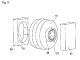
- a plurality of guide blocks 34 which are guide sections from the intermediate rollers 19, are supported by and fastened to the inside surfaces of the end plate 31 and support plate 33 of the support frame that face each other.
- Long guide holes 35 that are long in the radial direction of the ring-shaped roller 5a and the sun roller 4a are formed in the inside surfaces of the guide blocks 34.
- single-row deep-groove type ball bearings 36 are supported on the end section of each of the rotating shafts 20 by fitting the inner rings of the ball bearings 36 around the outside of the end sections of the rotating shafts 20 with an interference fit.
- the outer diameter of the outer rings of the ball bearings 36 is a little less than the width dimension of the long guide holes 35 (for example several ⁇ m to tens of ⁇ m). Therefore, the rotating shafts 20 are supported by the guide blocks 34 such that there is mostly no backlash in the circumferential direction, and so that a little displacement is possible in the radial direction of the ring-shaped roller 5a and the sun roller 4a.
- the outer circumferential surface of the intermediate rollers 19 is such that the middle section in the axial direction is a simple cylindrical surface, and the portions on both sides are partial conical convex inclined surfaces that are inclined in the same direction and at the same angle as the outer circumferential surface of the sun roller elements 8c. Therefore, the outer surfaces of the sun roller 4a, intermediate rollers 19 and ring-shaped roller 5a come in contact with each other, and contact area of the traction areas between them is maintained.
- the concave sections 38 are such that wide section 39 having a large width dimension in the radial direction and a narrow section 40 having a small width dimension in the radial direction are continuous in the circumferential direction.
- the arrangement direction of the narrow section 40 and the wide section 39 in the circumferential direction is the same among the concave sections 38.
- the sun roller elements 8c are combined so that they are the same but facing in opposite directions in the axial direction. Therefore, the arrangement direction of the wide section 39 and the narrow section 40 between one sun roller 8c and the other sun roller element 8c are opposite each other.
- strike plate sections 41 are provided on part of the inside surfaces (side surfaces on both sides that face each other) of the pair of cam plates 15a so that when the sun roller elements 8c are placed together they are in a portion that is aligned with the wide sections 39 of the concave sections 38.
- the strike plates 41 have a height dimension in the axial direction, and a width dimension in the radial direction so as to be able to enter into the wide sections 39 of the concave sections 38.
- This displacement causes a pressure force to be generated in the cam section in a direction in which the thickness dimension becomes larger in the axial direction, such that a pre-load for maintaining the surface pressure at the areas of traction between the sun roller 4a, the ring-shaped roller 5a and the intermediate rollers 19 is applied to the loading cam apparatuses 7a.
- the strike plate sections can be formed on the base end surface of the sun roller element
- concave sections can be formed in the surface of one side of the cam plates
- compression coil springs can be placed inside these concave sections.
- an elastic member other than a compression coil spring as the elastic member of applying a pre-load.
- the friction roller reducer 1a of this example constructed as described above, by functioning as described below, transmits power from the input shaft 2a to the outer shaft 3a while increasing torque at the same time as reducing the speed.
- the pair of cam plates 15a that fit around the outside of the input shaft 2a rotate, and due to the engagement between the balls 16, driven-side cam surfaces 17 and driving-side cam surfaces 18, the pair of sun roller elements 8c are pressed in a direction toward each other, and begin to rotate in the same direction and at the same speed as the input shaft 2a.
- the outer ring of the ball bearings 36 that support both end sections of the intermediate rollers 19 come in rolling contact with the inside surface of the long guide holes 35, so the intermediate rollers 19 displace smoothly outward in the radial direction. It is also possible to prevent the surface pressure at the traction areas between the sun roller 4a, intermediate rollers 19 and the ring-shaped roller 5a from becoming uneven, and so it is possible to keep the surface pressure at these traction areas proper, and improve the transmission efficiency of the friction roller reducer 1 even more.
- the rolling friction resistance stays at about 1/10 the sliding friction resistance, so the intermediate rollers 19 displace smoothly in the radial direction according to the rolling movement of the outer rings of the ball bearings 36 with respect to the inside surfaces of the long guide holes 35. Therefore, the traction coefficient at the areas of rolling contact between the outer circumferential surfaces of the intermediate rollers 19 and the inner circumferential surface of the ring-shaped roller 5a, and the traction coefficient between the outer circumferential surfaces of these intermediate rollers 19 and the outer circumferential surface of the sun roller 4a are nearly the same.
- the sun roller 4a that is constructed by the pair of sun roller elements 8c displaces a little in the axial direction, and due to this, the intermediate rollers 19 that come in rolling contact with the outer circumferential surface of the sun roller 4a also displace a little in the axial direction.
- the inner circumferential surface of the ring-shaped roller 5a that comes in rolling contact with the outer circumferential surfaces of the intermediate rollers 19 is a simple cylindrical surface.
- the long guide holes 35 that engage with the ball bearings 36 have a depth that allow displacement in the axial direction a certain amount. Therefore, displacement in the axial direction of the intermediate rollers 19 is performed smoothly, and these intermediate rollers 19 do not incline with respect to the rotation shafts 20.
- the compression coil springs 42 press the balls 16, which causes a pressure force in the cam section to be generated in loading cam apparatuses 7a.
- the compression coil springs 42 generate a pressure force in the cam section in the loading cam apparatuses 7a by nearly the same way as in the case when torque is inputted to the input shaft 2a. Even after torque is inputted to the input shaft 2a, the compression coil springs 42 continue to press the balls 16.
- FIG. 9 and FIG. 10 illustrate a second example of an embodiment of the present invention.
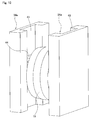
- guide blocks 34a having a concave U-shaped cross section are used. These guide blocks 34a are supported by and fasted to the support frame 32 (refer to FIG. 1 ) in a state in which lengthwise direction of the guide blocks 34a coincide with the radial direction of the sun roller 4a and the ring-shaped roller 5a.
- concave guide sections 43 are formed so as to be open on the end surfaces of both ends in the lengthwise direction.
- the width dimension of these concave guide sections 43 in the circumferential direction of the sun roller 4a and ring-shaped roller 5a is sufficiently larger than the width dimension of the long guide holes 35 (see FIG. 1 and FIG. 3 ) of the first example of the embodiment.
- These sliding blocks 44 engage with the concave guide sections 43 by way of a pair of sliding plates 46 for each sliding block 44 so as to be able to slide in the radial direction of the sun roller 4a and ring-shaped 5a.
- the construction and functions of the other parts are the same as in the first example of the embodiment, so any redundant drawings and explanations are omitted.
- FIG. 11 to FIG. 15 illustrate a third example of an embodiment of the present invention.
- the friction roller reducer 1b of this example as in the first example of the embodiment, is such that an input shaft 2a rotates and drives a sun roller 4a, the rotation of the sun roller 4a is transmitted to a ring-shaped roller 5a by way of a plurality of intermediate rollers 19a, and the rotation of the ring-shaped roller 5a is outputted from an output shaft 3a.
- the pivot shafts 52 and the rotation shafts 20a are parallel with each other, and the phases of each in the circumferential direction of the support frame 32a are offset by a large amount. More specifically, the offset in the circumferential direction of the pivot shafts 52 and the rotation shafts 20a is as large as possible, so the direction of an imaginary line that connects the pivot shafts 52 and the rotation shafts 20a is close to the direction of the tangent line of an imaginary arc that is centered around the center of the support frame 32a.
- the friction roller reducer 1b of this example transmits power from the input shaft 2a to the output shaft 3a while increasing torque at the same time as reducing the speed.
- the intermediate rollers 19a displace smoothly in the radial direction of the sun roller 4a and the ring-shaped roller 5a due to the pivotal displacement of the pivot frames 47 of the pivot mechanism. Therefore, it is possible to prevent the surface pressure at the traction areas between the sun roller 4a, intermediate rollers 19a and the ring-shaped roller 5a from becoming uneven, and it is possible to make the surface pressure at these traction areas proper and to further improve the transmission efficiency of the friction roller reducer 1b.
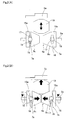
- FIG. 16 to FIG. 18B illustrate a fourth example of an embodiment of the present invention.
- This example is related to an improvement of the pivot mechanism when a pivot mechanism such as in the third example of an embodiment of the present invention is applied to a planetary roller type friction roller reducer.
- a large force outward in the radial direction of the support frame 32a is applied to the intermediate rollers 19a, which are planetary rollers, due to centrifugal force that is applied to the intermediate rollers 19a due to revolving motion.
- the construction of this example takes into consideration the situation described above, and reduces the outward force in the radial direction of the support frame 32b that is applied to the intermediate rollers 19a that function as planet rollers. Construction is also achieved that is capable of maintaining rolling fatigue of the circumferential surfaces of the sun roller 4a, intermediate rollers 19a and ring-shaped roller 5a and the transmission efficiency of the friction roller reducer without gross slipping occurring even during low-speed operation.
- counter weight sections 54 are provided in the pivot frames 47a, and as the support frame 32b rotates, it is possible to reduce the moment around the pivot shafts 52a that is applied to these pivot frames 47a.
- FIG. 19 to FIG. 21 illustrate a fifth example of an embodiment of the present invention.
- a feature of this example is construction for improving the rigidity of the support arms so that the tip end sections of the pair of support arms of a forked pivot frame do not separate from each other.
- the rigidity of each pair of support arms that are provided for each pivot frame is improved. The reason for this is explained below. In the case of the construction of the third example of the embodiment, as can be clearly seen from FIG. 14 and FIG.
- a force in the axial direction which is a force that causes displacement in the axial direction
- a force in the axial direction which is a force that causes displacement in the axial direction
- Various reasons are feasible for this kind of force occurring, such as when the characteristics of the circumferential surfaces (shape precision, surface roughness and the like) of the sun roller 4a, intermediate rollers 19a and ring-shaped roller 5a are irregular.
- a force in the axial direction also occurs in the case when the intermediate rollers 19a rotates (skew occurs) with the center axes of rotation of the intermediate rollers 19a (rotations shafts 20a) and the center axis of the sun roller 4a or ring-shaped roller 5a inclined.
- the pivot frames 47b are integrally formed by cutting or casting of a metal material such that the pivot frames 47b comprises a base section 51a and a pair of support arms 50a, 50b. These support arms 50a, 50b are flat and parallel with each other.
- a circular through hole 55 that is formed in the tip end section of one support arm 50a (the right support arm in FIG. 19 and FIG. 21 ) is formed so as to be concentric with a screw hole 56 that is formed in the other support arm 50b (left support arm in FIG. 19 and FIG. 21 ).
- the diameter of the root circle of this screw hole 56 is smaller than the inner diameter of the through hole 55.
- a bolt 57 that functions as the rotation shaft spans between the tip end sections of the support arms 50a, 50b.
- This bolt 57 comprises a cylindrical column section 58 in the middle section in the axial direction, a male screw section 59 on the tip end section (left end section in FIG. 21 ) having a smaller diameter than the cylindrical column section 58, and a head section 61 on the base end section (right end section in FIG. 21 ) having a diameter that is larger than the cylindrical column section 58.
- the outer circumferential surface of the cylindrical column section 58 is a smooth cylindrical surface for functioning as the inner ring raceway of a radial needle bearing 61.
- the outer diameter of the cylindrical column section 58 is a little smaller than the inner diameter of the through hole 55, and the diameter of the tip circle of the male screw section 59 is smaller than the outer diameter of the cylindrical column section 58.
- the bolt 57 With being inserted through the inner diameter side of the radial needle bearing 61, the bolt 57 is placed so that it spans between the tip end sections of the support arms 50a, 50b. Therefore, when the male screw section 59 of the bolt 57 is screwed into the screw hole 56 and further tightened, the intermediate roller 19b is supported between the support arms 50a, 50b so as to be able to rotate freely.
- a through hole 64 is formed in the base section 51a, with connecting the surfaces on both ends of the base section 51a, so that this through hole 64 is parallel with the bolt 57.
- a pivot shaft 52b is inserted through this through hole 64.
- both end section of the pivot shaft 52b protrude from both outside surfaces of the pivot frame 47b.
- both end sections of the pivot shaft 52b fit inside the support holes 53 (see FIG. 12 and FIG. 13 ) that are formed in the support frame 32a.
- the fitted section between the through hole 64 and the middle section of the pivot shaft 52b, and the fitted section between both end sections of the pivot shaft 52b and the support holes 53 one fitted section is a loose fit, and the other fitted section is an interference fit.
- the pivot frame 47b is supported by the support frame 32a such that pivotal displacement around the pivot shaft 52b is possible.
- a concave section 65 for preventing interference is formed in the rim section 48a.
- a low head bolt having a head section with a small thickness in the axial direction as the bolt, and provide a circular concave section (countersunk section) on the outside surface of the support arm 50a in the portion surrounding the opening of the through hole for inserting the bolt so that the head section does not protrude from the outside surface of the support arm 50a.
- these support arms 50a, 50b are such that by way of the engagement section between the outside surface of one support arm 50a and the stepped surface 63 on the base end side, and the screwed connection between the screw hole 56 and the male screw section 59, displacement in a direction away from each other is prevented. Therefore, even when the intermediate roller 19b is skewed, and the inside surfaces of the support arms 50a, 50b are pressed by the side surfaces in the axial direction of the intermediate roller 19b, the space between the support arms 50a, 50b do not spread apart.
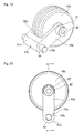
- FIG. 22 to FIG. 24 illustrate a sixth example of an embodiment of the present invention.
- the pivot frames 47c are formed by connecting and fastening a first element 66 and second element 67 by a second bolt 68.
- the first element 66 is formed by cutting or casting of metal material, and includes an integrated base section 51b and one support arm 50c.
- the second element 67 is constructed by a plate of metallic material and has a connecting plate section 69 which is abutted to one end surface of the base section 51b and another support arm 50d.
- first element 66 and second element 67 are connected and fastened by a second bolt 68 that is inserted through the base section 51b in a portion nearer the tip end of the pivot frame 47c than the pivot shaft 52b, to form the pivot frame 47c.
- the construction and functions of the other parts are the same as in the fifth example of the embodiment.
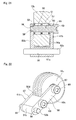
- FIG. 25 to FIG. 27 illustrate a seventh example of an embodiment of the present invention.
- the pivot frame 47d is constructed by connecting and fastening a first element 66a and a second element 67a by a second bolt 68a.
- a hollow cylindrical shaped bolt is used as the second bolt 68a.
- This second bolt 68a is provided around the pivot shaft 52c.
- the pivot shaft 52c is inserted through the inside of the second bolt 68a that connects and fastens the first element 66a and the second element 67a.
- the construction and functions of the other parts are the same as in the fifth and sixth example of the embodiment.
- An electric motor that is provided on the outside of this transmission case rotates and drives a sun roller 4b of the friction roller reducer 1c, the rotation of this sun roller 4b is transmitted to a ring-shaped roller 5b by a plurality of intermediate rollers 19c, and the rotation of this ring-shaped roller 5b is outputted by way of an output shaft 3b.
- a bearing case 70 is fastened to the wall section on one end of the transmission case so as to be oil tight.
- the output shaft 3b is supported on the inner-diameter side of this bearing case 70 in an oil tight state by an output-side ball bearing unit 25a and an output-side seal unit 26a so as to be able to rotate freely.
- This output shaft 3b and the ring-shaped roller 5b are connected by a connecting section 29a in a concentric state.
- intermediate rollers 19c are supported by a support frame 32c that is supported by and fastened to the transmission case by way of the same number of pivot frames 47e as the number of intermediate rollers 19c so as to be able to freely rotate and to displace freely a little in the radial direction of the support frame 32c.
- the support frame 32c is constructecd by a circular ring-shaped connecting plate section 72, and column sections 73 that protrude parallel with axial direction of the support frame 32c from a plurality of locations (three locations in the example in the figures) that are evenly spaced in the circumferential direction on the surface on one side in the axial direction of the connecting plate section 72.
- the cross-sectional shape of these column sections 73 is long in the radial direction of the support frame 32c.
- the pivot frames 47e are located in the portion between adjacent column sections 73 in the circumferential direction, and one end thereof in the circumferential direction of the support frame 32c pivotally displaces freely around the pivot shaft 52d, the base end of which are connected and fastened to the surface on one side in the axial direction of the connecting plate 72.
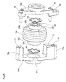
- Each of the pivot frames 47e is constructed by connecting and fastening both ends in the lengthwise direction of a pair of support plate sections 74a, 74b, which are separated in the axial direction, by a bolt 76, with the support plate sections 74a, 74b facing each other across connecting sections 75a, 75b.
- These connecting sections 75a, 75b are such that the base end sections of each are connected to the one support plate section 74a (left side in FIG. 35 , FIG. 36 and FIG. 38 ) so as to be integrated with this one support plate section 74a.
- Screw holes 77 are formed on the inside of the connecting sections 75a, 75b, and these screw holes 77 are open on the tip end surfaces of the connecting sections 75a, 75b.
- One connecting section 75a (bottom side in the FIG. 35 to FIG. 38 ) of these connecting sections 75a, 75b is thicker (larger cross-sectional area) than the other connecting section 75 (top side in FIG. 35 to FIG. 37 ), and in the portion further separated toward the end section than the screw hole 77, a pivot support hole 78 having a circular cross section is formed so as to pass through the connecting section 75a.
- first through holes 79 are formed in positions that are aligned with the screw holes 77
- a second through hole 80 is formed in the portion that is aligned with the pivot support hole 78.
- circular concave support sections 81 are formed in the portions in center sections of the support plate sections 74a, 74b that are aligned with each other.
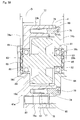
- an intermediate roller 19c is formed so as to be integrated and concentric with a rotation shaft 20b. Both end sections of the rotation shaft 20b protrude further in the axial direction than the surfaces on both ends in the axial direction of the intermediate roller 19c, and the portion near the protruding tip ends have a smaller diameter than the portion near the base end such that a stepped section 82 is formed in between the portion near the tip end and the portion near the base end.
- Inner rings 83 of single-row deep-groove ball bearings 36c are fitted around both end sections of this kind of rotation shaft 82 with an interference fit, and the end surfaces in the axial direction of these inner rings 83 come in contact with the stepped section 82.
- the outer rings 84 of the ball bearings 36 have an outer diameter just enough to fit inside the concave support section 81 without backlash in the radial direction but so as to be able to displace in the axial direction. Furthermore, with the end surfaces in the axial direction of the inner rings 83 in contact with the stepped sections 82, the space d between the outer end surfaces in the axial direction of the outer rings 84 (end surface on opposite sides from each other) is sufficiently smaller than the space D between the bottom surfaces of the concave support sections 81 (d ⁇ D).
- the intermediate roller 19c described above is supported by the pivot frame 47e by way of ball bearings 36c so as to be able to rotate freely, and so as to be able to displace a little in the axial direction.
- the rotation resistance (dynamic torque) of these ball bearings 36c is small, so it is possible keep the rotation resistance of the intermediate roller 19c low, and to improve the transmission efficiency of the friction roller reducer 1c.
- elastic members such as wave plate springs 85 are provided between the surface on the outside ends in the axial direction of the outer rings 84 and the bottom surface of the concave support sections 81, and these springs elastically presses the intermediate roller 19c toward the center in the axial direction.
- the elastic force of the wave plate springs is set to as small as possible but to still allow the intermediate roller 19c to displace in the axial direction due to the operation of the loading cam apparatuses 7b.
- the intermediate rollers 19c are supported by the middle section of the pivot frame 47e so that there is no backlash, however, when the rigidity against a moment in the direction that causes the center axes of the intermediate rollers 19c to incline is suitably low, the intermediate rollers 19c are supported so as to be able to freely rotate and to displace in the axial direction due to inevitable manufacturing error of each of the parts.
- the main purpose of installing the wave plate springs 85 is to position the intermediate roller 19c in a center position in the axial direction with respect to the pivot frame 47e, and to simplify the work for assembling the intermediate rollers 19c, sun roller 4b and ring-shaped roller 5b. Therefore, when there is no external force acting on the intermediate rollers 19c, the elastic force of the wave plate springs 85 can be a small value that is just enough to return the intermediate rollers 19c to the center position.
- the inner rings 83 of the ball bearings 36c are fitted and fastened around the outside of both end sections of the rotation shaft 20b, after which the support plate sections 74a, 74b are placed close to each other.
- the wave plate springs 85 are inserted into the concave support sections 81.
- the support plate sections 74a, 74b brought close together.
- the support frame 32c is supported by and fastened to the inside of the transmission case by screwing bolts 88a, 88b that are inserted though the column sections 73 into screw holes that are formed on a fastening wall section (not illustrated in the figure) that is provided inside the transmission case, and further tightening the bolts 88a, 88b.
- the pivot frames 47e are supported between the connecting plate section 72 and the fastening wall section or the like so as to be able to pivotally displace a little around the pivot shafts 52d.
- supply paths 89 for traction oil which is a lubricant, are provided on the inside of the column sections 73.
- the downstream end of these supply paths 89 is open toward the outer circumferential surface of the sun roller 4b (see FIG. 28 and FIG. 29 ), and traction oil is fed to the contact areas (traction areas) between the circumferential surfaces of the sun roller 4b, intermediate rollers 19c and ring-shaped roller 5.
- This kind of lubrication construction for supplying traction oil is also not related to an aspect of the present invention, and other construction could also be used, so this construction is only illustrated in the figures and a detailed explanation is omitted.
- the pivot frames 47e of the friction roller reducer 1c of this example are such that both end in the lengthwise direction of a pair of support plate sections 74a, 74b that is provided for each of these pivot frames 47e are connected together by connecting sections 75a, 75b and bolts 76. Therefore, the support plate sections 74a, 74b are such that both end sections in the lengthwise direction of each are connected together, so even when the inside surface of one support plate section 74a (74b) of these support plate sections 74a, 74b is pressed by an intermediate roller 19c, the space between the support plate sections 74a, 74b is not widened.
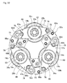
- the pivot shafts 52d which support one end section of the pivot frames 47e so as to be able to pivot freely, are uniformly located in the circumferential direction inside the ring-shaped space 9b between the outer circumferential surface of the sun roller 4b and the inner circumferential surface of the ring-shaped roller 5b.
- three pivot shafts 52d are uniformly located in the circumferential direction inside this ring-shaped space 9b at a central angle pitch of 120°.
- the distances L between the pivot shafts 52d that support the end sections of the pivot frames 47e and the rotation shafts 20b that are provided in the middle sections of these pivot frames 47e are the same between each of these pivot frames 47e.
- the outer circumferential surfaces of the intermediate rollers 19c come uniform contact with the outer circumferential surface of the sun roller 4b and the inner circumferential surface of the ring-shaped roller 5b. Moreover, when the intermediate rollers 19c displace inside the ring-shaped space 9b in the radial direction of this ring-shaped space 9b due to the movement of the sun roller elements 8d of the sun roller 4b away from and toward the intermediate rollers 19c, the rotation shafts 20b that support these intermediate rollers 19c move in an arc shape having the same radius of curvature.
- the intermediate rollers 19c transmit nearly the same torque, so it is possible to keep the surface pressure at the traction areas, which are areas of rolling contact between the sun roller 4b, the intermediate rollers 19c and the ring-shaped roller 5b, uniform, and thus it is possible to improve the transmission efficiency of the friction roller reducer 1c.
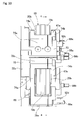
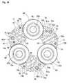
- FIG. 40 and FIG. 41 illustrate a ninth example of an embodiment of the present invention.
- the base end sections of the same number of stopper pins 91 as there are pivot frames 47e are supported by and fastened to a base plate 90 of a support frame 32d. Therefore, in the case of this example, protruding sections 92 are formed at three locations on the outer circumferential edge of the base plate 90 that are evenly spaced in the circumferential direction, and small-diameter screw sections that are formed on the base end sections of the stopper pins 91 are screwed into screw holes (not illustrated in the figure) that are formed in these protruding sections 92, and further tightened.
- the outer circumferential surfaces of part of these stopper pins 91 face the edges on the outer diameter side of corresponding pivot frames 47e in the radial direction of the support frame 32d.
- the minimum value of this width dimension is maintained so as to allow the outer circumferential surfaces of the intermediate rollers 19c that are supported by the pivot frames 47 to come in contact with the inner circumferential surface of the ring-shaped roller 5b such that the surface pressure at the traction areas, which are areas of rolling contact between these circumferential surfaces, sufficiently increases.
- the maximum value is regulated to prevent the diameter of the circumscribed circles of the intermediate rollers 19c from greatly exceeding the inner diameter of the ring-shaped roller 5b, so as not to hinder the assembly work of assembling the intermediate rollers 19c on the inner-diameter side of the ring-shaped roller 5b.
- the stoppers 91 restrict the pivotal displacement of the pivot frames 47e around the pivot shafts 52d. Therefore, the even when the intermediate rollers 19c displace outward in the radial direction of the support frame 32d, it is possible to keep the diameter of the circumscribed circle of the intermediate rollers 19c indicated by the chain line y in FIG. 41A small. Moreover, the tip end sections of the pivot frames 47e do not protrude to the outside in the radial direction further than this circumscribed circle.
- these intermediate rollers 19c can be assembled on the inner-diameter side of the ring-shaped roller 5b by causing these intermediate rollers 19c to displace only a little inward in the radial direction of the support frame 32d.
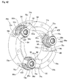
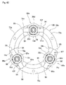
- FIG. 42 to FIG. 45 illustrate a tenth example of an embodiment of the present invention.
- a feature of the friction roller reducer of this example is, for the same reason as in the eighth example of the embodiment, is construction for improving the rigidity of a pair of support plate sections 74c, 74d of a pivot frames 47f that support intermediate rollers 19d so as to be able to rotate freely, and to bring the displacement direction of the intermediate rollers 19d close to the radial direction of the support frame 32e.
- the construction and functions of the other parts are the same as in the other examples of the embodiment, so drawings and explanations of identical parts are omitted or simplified, with the following explanation centering on the feature of this example.
- the inside surfaces 94 on both end section in the circumferential direction of these concave support sections 81a which are constructed by the both end surfaces in the circumferential direction of the column sections 73a, are formed such that a pair of inside surfaces 94 that partition both end surfaces in the circumferential direction of these concave support sections 81a are flat surfaces that are parallel with each other. Furthermore, preferably these inside surfaces 94 are partial cylindrical concave surfaces. In this case, the radius of curvature of the partial cylindrical concave surface of these inside surfaces 94 is equal to or greater than the space between the pair of inside surfaces 94 of each concave support section 81a.
- the radius of curvature of an inside surface 94 is the same as this space, or is a little greater (within 10% greater) than this space.
- the center of curvature of each in the radial direction of the support frame 32e is in a portion in the center section of the inside surface 94 or in a portion a little further toward the outside than this center section.
- the pivot frames 47f are respectively assembled inside these concave support sections 81a so as to be able to pivotally displace around the area of contact between the outside surface 95 of one end section in the lengthwise direction (circumferential direction of the connecting plate section 72a) of each of the pivot frames 47f and the inside surface 94.
- This kind of pivot frame 47f is constructed by placing both end sections in the lengthwise direction of a pair of support plate sections 74c, 74d that are separated in the axial direction together by way of connecting sections 75c, and connecting and fastening together this pair of support plate sections 74c, 74d with bolts 76a.
- the connecting sections 75c, 75c are such that the base end section is continuous with one (front side in FIG. 42 and back side in FIG.
- support plate section 74c and are integrated with that one support plate section 74c.
- a screw hole (not illustrated in the figures) is formed in the connecting sections 75c so as to be open on the tip end surface of the connecting sections 75c.
- through holes (not illustrated in the figure) are formed in portions on both end sections in the lengthwise direction of the other (back side in FIG. 42 and front side in FIG. 44 ) support plate section 74c that are aligned with screw hole that are formed on the inside of the connecting sections 75c.
- the outside surfaces 95 of the connecting sections 75 which are the outer surfaces on both end sections in the lengthwise direction of the pivot frame 47f can partial cylindrical convex surfaces.
- the radius of curvature of the partial cylindrical convex surfaces of these outside surfaces 95 is sufficiently smaller than the radius of curvature of the partial cylindrical concave surfaces of the inside surfaces 94 on both end sections in the circumferential direction of the concave support sections 81a.
- the centers of curvature of the outside surfaces 95 are located on the center axes of the rotation shafts 20c that are located in the middle section in the lengthwise direction of the pivot frames 47f.
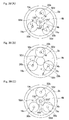
- FIG. 46A illustrates the state wherein the intermediate roller unit 86a is located in the neutral state when the friction roller reducer is not transmitting torque or is transmitted only a small torque.
- the intermediate roller unit 86a is such that from this neutral state the pivot frame 47f pivotally displaces around the area of contact between the outside surface 95 of the side on one end in the lengthwise direction (left side in FIG. 46B ) and the inside surface 94 of the concave support section 81a outward in the radial direction of the support frame 32e as indicated by the arrow ⁇ in (b) of FIG. 46B .
- the pivot frames 47f are such that both end sections in the lengthwise direction of the pair of support plate sections 74c, 74d that are provided for each pivot frame 47f are connected by connecting sections 75c and bolts 76a. Therefore, the support plate sections 75c are such that, even when the inside surface of one of the support plate sections 74c (74d) of the support plate sections 74c, 74d, having construction such that both end sections in the lengthwise direction are connected, is pressed by the intermediate roller 19d, the space between these support place sections 74c, 74d is not expanded.
- the pivot centers of the intermediate roller units 86a are not the pivot shafts 52 (see FIG. 11 to FIG. 14 ) located on the tip end sections of the pivot frames 47, but are the areas of contact between the outside surfaces 95 of these pivot frames 47f and the inside surfaces 94 of the concave support sections 81a. Therefore, even though the length dimension of these pivot frames 47f are not long, when the intermediate rollers 19d displace in the radial direction, the pivot radii of the pivot frames 47f can be made large. Therefore, when the intermediate rollers 19d displace in the radial direction of the support frame 32e, the displacement directions of the intermediate rollers 19d can be made to be close to the radial direction. As a result, the contact between the outer circumferential surfaces of the intermediate rollers 19d and the inner circumferential surface of the ring-shaped roller 5b can be made even more stable.
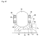
- FIG. 47 illustrates an eleventh example of an embodiment of the present invention.
- a loading cam apparatus 7c is provided on only one side in the axial direction of the sun roller 4c.
- only one sun roller element 8e of the pair of sun roller elements 8e, 8f of the sun roller 4c (right sun roller element 8e in FIG. 47 ) is supported so as to be able to rotate relative to the input shaft 2c, and the other sun roller element 8f (left sun roller element 8f in FIG. 47 ) is supported by and fastened to the input shaft 2c.
- FIG. 48 illustrates a twelfth example of an embodiment of the present invention.
- the input shaft 2d of the friction roller reducer 1d is itself the output shaft 98 of the electric motor 87.
- the input shaft 2ds and the output shaft 98 are concentric with each other and are integrated into a single shaft.
- the construction and functions of the other parts are the same as in the other examples of the embodiment, so any redundant explanations are omitted.
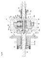
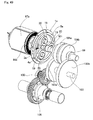
- FIG. 49 is a thirteenth example of an embodiment of the present invention, and illustrates a drive unit for an electric automobile in which the friction roller reducer is assembled.
- This drive unit for an electric automobile comprises a friction roller reducer 1e, a transmission apparatus 99, and a rotation transmission apparatus 100.
- this friction roller reducer 1e the same construction as in any of the other examples of the embodiment is used, and the input shaft 2e of this friction roller reducer 1e and the output shaft 98a of the electric motor 97a are arranged so as to be concentric with each other, and are connected so that torque can be transmitted.
- the output shaft (omitted in the figure) of the friction roller reducer 1e and the input-side transmission shaft 101 of the transmission apparatus 99 are arranged so as to be concentric with each other, and are connected so that torque can be transmitted.
- the transmission apparatus 99 is provided with a pair of gear transmission mechanisms 103a, 103b having different reduction ratios between the input-side transmission shaft 101 and the output-side transmission shaft 102.
- the pair clutch mechanisms 104a, 104b By switching between the pair clutch mechanisms 104a, 104b, only one gear transmission mechanism 103a (103b) is in a state capable of transmitting power, and the reduction ratio between the input-side transmission shaft 101 and the output-side transmission shaft 102 can be converted between two stages, high and low.
- the rotation transmission apparatus 100 is a typical gear transmission mechanism that is a combination of a plurality of gears, and is such that the rotation from the output-side transmission shaft 102 is transmitted to the input section of a differential gear 105, and then rotates and drives a pair of left and right driven wheels.
- the drive unit for an electric automobile of this example described above With the construction of the drive unit for an electric automobile of this example described above, electric energy is efficiently used, so even when a compact, high-speed (for example a maximum rotational speed of 30,000 min -1 ) motor is used as the electric motor 97a, it is possible to suppress vibration and noise during operation.
- a friction roller reducer 1e is used as a first stage reducer, so the occurrence of vibration in the high speed rotating portion is suppressed.
- the rotational speed of the transmission apparatus 99 and the rotation transmission apparatus 100 which are both gear transmission mechanisms, is kept at about the same level (maximum of several thousand min -1 ) as the operation speed of the portion of the transmission apparatus of an automobile in which a typical gasoline engine is mounted, so unpleasant vibration and noise do not occur in any portion.
- the relationship between the traveling speed and acceleration of the vehicle is smooth and is close to that of an automobile in which a gasoline engine is mounted.
- a power transmission apparatus having a large reduction ratio is provided between the output shaft (omitted in FIG. 49 ) of the electric motor 97a, which is the driving source of the electric automobile, and the input shaft of the differential gear 105 that is connected to the driven wheels, the relationship between the acceleration (G) and the traveling speed (km/h) of the automobile becomes as the left half section of the solid line "a" in FIG. 50 that is made to be continuous with the chain line "b".
- the acceleration performance at low speed are excellent, however high-speed travel is not possible.
- the friction roller reducer of the present invention as a reducer that is capable of high-speed operation, and in which large vibration does not occur during operation, is not limited to a drive system of an electric automobile, and can be assembled in a rotation transmission mechanism of all kinds of machinery. Moreover, the present invention can also be applied to a planetary roller type of friction roller reducer with the condition that the operation speed does not become very fast.
- the type of transmission apparatus that is assembled between the friction roller reducer and the rotation transmission apparatus does not really matter, and in addition to the construction illustrated in the figure, it is also possible to employ a planet gear type of transmission apparatus.
- a continuously variable transmission apparatus it is possible to obtain a relationship between the traveling speed and acceleration of vehicle that is smoother and even more ideal, as illustrated in FIG. 50 .
Landscapes
- Engineering & Computer Science (AREA)
- General Engineering & Computer Science (AREA)
- Mechanical Engineering (AREA)
- Power Engineering (AREA)
- Friction Gearing (AREA)
Abstract
Description
- The present invention relates to a friction roller reducer for transmitting torque from an electric motor to driven wheels when assembled in the drive system of an electric automobile for example, and to a drive unit for an electric automobile in which this friction roller reducer is assembled.
- In order to improve the convenience of electric automobiles that in recent years have begun to be widespread, it is very important that the distance traveled per one electric charge be lengthened by improving the efficiency of the electric motor. In order to improve the efficiency of the electric motor, using a compact electric motor that rotates at high speed, and transmitting the rotation of the output shaft of this electric motor to the driven wheels after reducing the rotating speed is effective. Of the reducers of an electric automobile, a first-stage reducer that is directly connected to the output shaft of the electric motor has a very fast operating speed, and it is necessary that vibration and noise be suppressed during operation. Therefore, use of a friction roller reducer as at least the first-stage roller is feasible. Friction roller reducers that can be used for this purpose are known and disclosed in
JP 59-187154 A JP 61-136053 A JP 2004-116670 A JP 2004-116670 A FIG. 51 to FIG. 53 . - This friction roller reducer 1 comprises an
input shaft 2, andoutput shaft 3, asun roller 4, ring-shaped roller 5, a plurality ofplanet rollers 6 as intermediate rollers, and aloading cam apparatus 7. - Of these, the
sun roller 4 comprises a pair ofsun roller elements input shaft 2 with a gap between the tip end surfaces of each and are capable of relative rotation with respect to theinput shaft 2. The outer circumferential surfaces of thesesun roller elements overall sun roller 4 is small in the middle section in the axial direction and becomes larger going toward both end sections. - Moreover, the ring-
shaped roller 5 is overall ring shaped, and is supported by and fastened to a stationary portion such as a housing (not illustrated in the figure) so as to be arranged around thesun roller 4 and so as to be concentric with thesun roller 4. The inner circumferential surface of the ring-shaped roller 5 functions as a rolling contact surface and is inclined in a direction such that the inner diameter becomes larger going toward the center section in the axial direction. - The plurality of
planet rollers 6 are arranged at a plurality of locations in the circumferential direction of a ring-shaped space 9 between the outer circumferential surface of thesun roller 4 and the inner circumferential surface of the ring-shaped roller 5. Theplanet rollers 6 are arranged so as to be parallel with theinput shaft 2 and theoutput shaft 3, and each is supported around aplanet shaft 10, which is a rotating shaft, by way of radial needle bearing so as to be able to rotate freely. The end sections of theseplanet shafts 10 and supported by and fastened to a carrier 11, which is a support frame, that is connected and fastened to the base end section of theoutput shaft 3. The outer circumferential surface of theplanet rollers 6 is a convex curved surface having a generating line that is a partial arc shape, and each comes in rolling contact with the outer circumferential surface of thesun roller 4 and the inner circumferential surface of the ring-shaped roller 5. - Furthermore, the
loading cam apparatus 7 is provided between onesun roller element 8a of thesun roller elements input shaft 2. In order for this, asupport ring 13 is fastened to the middle section of theinput shaft 2 by aretaining ring 12, and adisc spring 14,cam plate 15 and a plurality ofballs 16 as rolling bodies are located in that order from the side of thesupport ring 13 between thesupport ring 13 and the onesun roller element 8a. Driven-side cam surfaces 17 and driving-side cam surfaces 18 are provided at a plurality for locations in the circumferential direction of each the base end surface of the onesun roller element 8a and the surface on one side of thecam plate 15 that face each other. Thesecam surfaces - As illustrated in
FIG. 53A , this kind ofloading cam 7 is such that when theinput shaft 2 is stopped, theball 16 is located in the deepest portion of the driven-side cam surface 17 and the driving-side cam surface 18. In this state, the elastic force of thedisc spring 14 presses the onesun roller element 8a toward the othersun roller element 8b. On the other hand, as illustrated inFIG. 53B , as theinput shaft 2 rotates, theball 16 moves to the portion of thecam surfaces sun roller element 8a andcam plate 15 is opened up, and thesun roller element 8a is pressed toward thesun roller element 8b. As a result, thesun roller element 8a is rotated and driven while being pressed toward thesun roller element 8b with the larger force of the elastic force of thedisc spring 14 and the thrust force that is generated by theball 16 riding up on thecam surfaces - During operation of the friction roller reducer 1 described above, the space between the
sun roller elements loading cam apparatus 7. Also, the surface pressure at the rolling contact sections between the outer circumferential surface of thesun roller 4 that is constructed by thesesun roller elements planet rollers 6 increases. As the surface pressure increases, theplanet rollers 6 are pressed outward in the radial direction of thesun roller 4 and ring-shaped roller 5. When this happens, the surface pressure at the rolling contact areas between the inner circumferential surface of the ring-shaped roller 5 and the outer circumferential surface of theplanet gears 6 also increases. As a result, the surface pressure at a plurality of rolling contact areas between theinput shaft 2 andoutput shaft 3, which are traction sections for transmitting power, increases according to the size of the torque to be transmitted between theinput shaft 2 and theoutput shaft 3. - When the
input shaft 2 is rotated in this state, this rotation is transmitted to theplanet rollers 6 from thesun roller 4, and theseplanet rollers 6 revolve while rotating around thesun roller 4. The revolving motion of theseplanet rollers 6 is outputted by theoutput shaft 3 by way of the carrier 11. The surface pressure at the traction sections becomes proper according to the size of the torque that is to be transmitted between theinput shaft 2 and theoutput shaft 3, so excessive sliding at the traction sections does not occur, and rolling resistance due to excessive surface pressure at traction sections does not uselessly increase. - During operation of the conventional friction roller reducer 1, the
planet rollers 6 displace a small amount (for example a maximum of several hundred µm) in the radial direction of thesun roller 4 and ring-shaped roller 5 due to the movement of theloading cam apparatus 7. In other words, as the torque that is inputted to the friction roller reducer 1 from theinput shaft 2 changes, the dimension in the axial direction of theloading cam apparatus 7 changes (expands or contracts), and the dimension on the radial direction of the portion of the onesun roller element 8a that has entered on the inside of theplanet roller 6 changes. Due to this change, theplanet rollers 6 displace in the radial direction of thesun roller 4 and the ring-shaped roller 5, however, in the construction illustrated inFIG. 51 , this displacement is only allowed due to the elastic displacement of theplanet shafts 10. Therefore, when the torque changes, displacement of theplanet rollers 6 in the radial direction is not always performed smoothly, and it becomes easy for the surface pressure at the traction areas to become ununiform. When the surface pressure is not uniform, the transmission efficiency of the friction roller reducer 1 worsens. - As technology related to the present invention, construction that increases the operation response is disclosed in
JP 2004-52729 A -
[Patent Literature 1] JP 59-187154 A [Patent Literature 2] JP 61-136053 A [Patent Literature 3] JP 2004-116670 A [Patent Literature 4] JP 2004-52729 A - In consideration of the problems described above, the object of the present invention is to achieve construction of a friction roller reducer in which the displacement of an intermediate roller can be performed smoothly as the thickness in the axial direction of a loading cam apparatus changes, and that can obtain excellent transmission efficiency, and the a drive unit for an electric automobile in which this friction roller reducer is assembled.
- The friction roller reducer of the present invention comprises a sun roller, a ring-shaped roller, a plurality of intermediate rollers, a loading cam apparatus and a pivot mechanism.
- The sun roller comprises a pair of sun roller elements that are separated in the axial direction and located around an input shaft, so that when there is a space between the tip end surfaces of each, each is concentric and is capable of relative rotating with respect to the input shaft. Moreover, each of the sun roller elements has an outer circumferential surface, which is a rolling contact surface, that has an inclined surface that is inclined in a direction such that the outer diameter thereof becomes smaller going toward the respective tip end surface.
- The ring-shaped roller is located around the outside of the sun roller so as to be concentric with the sun roller, and has an inner circumferential surface, which is a rolling contact surface.
- Moreover, a plurality of intermediate rollers are supported at a plurality of locations in the circumferential direction of a ring-shaped space between the outer circumferential surface of the sun roller and the inner circumferential surface of the ring-shaped roller so as to be able to rotate freely around rotation shafts that are arranged parallel with the input shaft, and each intermediate roller has an outer circumferential surface that comes in rolling contact with the outer circumferential surface of the sun roller and the inner circumferential surface of the ring-shaped roller.
- The loading cam apparatus is provided between at least one movable sun roller element of the sun roller elements and the input shaft, and as the input shaft rotates, causes the movable sun roller element to rotate while pressing the movable sun roller element in the axial direction toward the other sun roller element. The loading cam apparatus has: driven-side cam surfaces that are provided at a plurality of locations in the circumferential direction of the base end surface of the movable sun roller element, and each is shaped such that the depth in the axial direction thereof gradually changes in the circumferential direction and becomes more shallow going toward the end section; driving-side cam surfaces that are provided at a plurality of locations in the circumferential direction of the surface on one side of a cam plate that faces the base end surface of the movable sun roller element, and each is shaped such that the depth in the axial direction thereof gradually changes in the circumferential direction and becomes more shallow going toward the end section; and a plurality of rolling bodies that are held between the each of the driven-side cam surfaces and the driving-side cam surfaces.
- Furthermore, the pivot mechanism causes each of the intermediate rollers to pivotally displace in the radial direction of the sun roller and the ring-shaped roller as the thickness in the axial direction of the sun roller changes due to displacement in the axial direction of the movable sun roller element.
- The friction roller reducer of the present invention is such that one member of the ring-shaped roller and a member that supports the rotation shafts is fastened, and the other member is connected to an output shaft, such that this other member rotates and drives the output shaft.
- Preferably, the portion of the outer circumferential surface of the sun roller elements that come in rolling contact with the outer circumferential surface of the intermediate rollers is a partial conical convex inclined surface that is inclined in a direction such that the outer diameter becomes smaller going toward the tip end surface. Moreover, the outer circumferential surfaces of the intermediate rollers are complex curved surfaces that comprise a cylindrical convex surface in the middle section in the axial direction, the outer diameter in the axial direction thereof being constant, and a pair of partial conical convex shaped inclined surfaces on the portions near both ends in the axial direction, that are inclined in a direction such that the outer diameter becomes smaller going toward the both end surface in the axial direction. And the inner circumferential surface of the ring-shaped roller is a cylindrical concave surface, the inner diameter thereof being constant in the axial direction.
- More specifically, construction can be employed wherein the member that supports the rotation shafts is stationary and does not rotate, and the intermediate rollers only rotate around the respective rotation shafts that are provided on the member that supports the rotation shafts, and transmit torque from the sun roller to the ring-shaped roller, and this ring-shaped roller is concentrically connected with the output shaft and rotates together with the output shaft.
- Alternatively, construction can be employed wherein the ring-shaped roller is stationary and does not rotate, and the member that supports the rotation shafts rotates; the intermediate rollers are planet rollers that revolve around the sun roller together with the member that supports the rotation shafts while also rotating around the respective rotation shafts that are provided on the member that supports the rotation shafts; and the member that supports the rotation shafts is concentrically connected to the output shaft, and rotates together with the output shaft.
- Preferably the pivot mechanism of the friction roller reducer of the present invention is constructed by: a support frame for supporting the end section of the rotation shaft of the intermediate roller so as to be able to rotate freely; a long guide section that is long in the radial direction of the sun roller and the ring-shaped roller; and a rolling bearing that comprises an inner ring that is fitted around and fastened to the outside of the end section of the rotation shaft, and an outer ring that engages with the guide section so as to be able to displace in the radial direction of the sun roller and the ring-shaped roller.
- Alternatively, the pivot mechanism supports is constructed by: a plurality of pivot frames that supports the intermediate rollers so as to be able rotate freely around the respective rotation shafts, and a support frame that supports these pivot frames so as to be able to displace in the radial direction of the sun roller and the ring-shaped roller.
- When the pivot mechanism is constructed by the pivot frames and the support frame, the pivot frames are supported by the support frame so as to be able to pivotally displace around each of a plurality of pivot shafts that are parallel with the rotation shafts and that are located on the support frame such that the phase of the pivot shafts in the direction of rotation of the sun roller is separated from the rotation shafts; and these pivot frames support the rotation shafts so as to be able to displace in the radial direction of the sun roller and the ring-shaped roller.
- In this case, preferably, each pivot frame comprises a base section having the pivot shaft, and a pair of support arms that extend in the same direction as each other and essentially parallel from both end sections in the axial direction of the base section. Both end sections of the rotation shaft are supported between the tip end sections of these support arms.
- Furthermore, preferably, the rotation shafts are constructed by bolts each having: a circular column section in the middle section in the axial direction, a male screw section on the tip end section having a diameter that is smaller than the circular column section, and a head section on the base end section having a diameter that is larger than the circular column section. Moreover, a through hole having a smaller diameter than the head section is formed in one of the tip end sections of each pair of support arms of the pivot frames, and a screw hole in which the male screw section can be screwed is formed in the other tip end section so as to be concentric with the through hole; and by inserting the circular column section through the through hole and screwing the male screw section in the screw hole, the rotation shaft is supported and fastened between the pair of support arms, and the space between the pair of support arms is prevented from expanding.
- In this case, additionally, construction can be employed wherein a counterweight section is provided on the opposite side from the tip end section of the base section, and as the intermediate roller revolves, a force outward in the radial direction of the support frame that is applied to the planet roller due to a centrifugal force is reduced or cancelled out by the centrifugal force that is applied to the counterweight section.
- In construction where the pivot frames are supported by the support frame so as to be able to pivotally displace around each of a plurality of pivot shafts that are parallel with the rotation shafts and that are located on the support frame such that the phase of the pivot shafts in the direction of rotation of the sun roller is separated from the rotation shafts, alternatively, each of the pivot frames can be formed by connecting and fastening together by way of connecting sections both ends in the lengthwise direction of a pair of support plate sections that are separated in the axial direction, and supports both end sections of the rotation shaft between the middle sections in the lengthwise direction of these support plate sections.
- Moreover, when the pivot mechanism is constructed by a plurality of pivot frames and a support frame that supports these pivot frames, alternatively, the structure can be adopted where the support frame comprises concave support sections at a plurality of locations in the circumferential direction of the surface on one side in the axial direction; each pivot frame is formed by connecting and fastening together by way of connecting section both ends in the lengthwise direction of a pair of support plate sections that are separated in the axial direction; both end sections of the rotation shaft are supported between the middle sections in the lengthwise direction of these support plate sections; and the pivot frames is supported inside each of the concave support section so as to be able to pivotally displace around the area of contact between the outside surface of one end section in the lengthwise direction of each of the pivot frames and an inside surface of each of the concave support sections.
- The drive unit for an electric automobile of the present invention comprises: an electric motor; a friction roller reducer having an input shaft that rotates together with an output shaft of the electric motor; a transmission apparatus having an input-side transmission shaft that is rotated and driven by an output shaft of the friction roller reducer, and an output-side transmission shaft, where the reduction ratio between this input-side transmission shaft and the output-side transmission shaft can be changed between at least two stages, high and low; wherein the friction roller reducer is constructed by a friction roller reducer of the present invention described above.
- With the friction roller reducer of the present invention constructed as described above, construction of a friction roller reducer is achieved wherein displacement of intermediate rollers due to the change in thickness in the axial direction of loading cam apparatuses can be performed smoothly, and excellent transmission efficiency can be obtained. With such characteristics, when this friction roller reducer is assembled in a drive unit for an electric automobile, a highly efficient drive unit is achieved, and it is possible to lengthen the distance that can be traveled per electric charge.
-
-
FIG. 1 is a cross-sectional view of a first example of an embodiment of the present invention. -
FIGS. 2A and 2B are schematic diagrams for explaining the mechanism for applied a preload in the first example of an embodiment of the present invention. -
FIG. 3 is an exploded perspective drawing illustrating the construction of a pivot mechanism that supports the rotation shaft of an intermediate roller so as to be able to displace in the radial direction of a sun roller and ring-shaped roller in the first example of an embodiment of the present invention. -
FIG. 4 is a perspective view illustrating the assembled state of an intermediate roller and pivot mechanism in the first example of an embodiment of the present invention. -
FIG. 5 is a perspective drawing that illustrates balls and compressing coil springs of a sun roller element and cam plate that have been removed from the right side in the center section ofFIG. 1 . -
FIG. 6 is a schematic diagram for explaining the direction of preloading applied by compression springs in the first example of an embodiment of the present invention. -
FIG. 7 is a schematic diagram for explaining the engaged state between the cam surfaces on the driving side and the driven side and the balls in the first example of an embodiment of the present invention. -
FIG. 8 is a graph that illustrates the relationship between the size and direction of torque that is applied to the input shaft and the pressure in the axial direction that is generated by a loading cam apparatus in the first example of an embodiment of the present invention. -
FIG. 9 is a drawing similar toFIG. 3 , and illustrates a second example of an embodiment of the present invention. -
FIG. 10 is a drawing similar toFIG. 4 , and illustrates the second example of an embodiment of the present invention. -
FIG. 11 is a cross-sectional drawing illustrating a third example of an embodiment of the present invention. -
FIG. 12 is a perspective drawing illustrating the construction of a pivot mechanism that supports a rotating shaft of an intermediate roller so as to be able to displace in the radial direction of a sun roller and ring-shaped roller in the third example of an embodiment of the present invention. -
FIG. 13 is an exploded perspective drawing of the pivot mechanism illustrated inFIG. 12 of the third example of an embodiment of the present invention. -
FIG. 14 is a perspective drawing illustrating only one unit of a combination of a pivot frame and intermediate roller that has been removed of the third example of an embodiment of the present invention. -
FIG. 15 is an exploded perspective drawing illustrating the unit that is illustrated inFIG. 14 with the unit further separated into the pivot frame and intermediate roller. -
FIG. 16 is a drawing similar toFIG. 13 , and illustrates a fourth example of an embodiment of the present invention. -
FIG. 17 is a drawing similar toFIG. 12 , and illustrates the fourth example of an embodiment of the present invention. -
FIGS. 18A and 18B are drawings for explaining the size of the centrifugal force that is applied to a planet roller as the planet roller revolves during operation of a friction roller reducer of the fourth example of an embodiment of the present invention, whereinFIG. 18A is a partial front view illustrating the case of employing the construction of this example, andFIG. 18B is a partial front view illustrating the case of employing the construction of the first example of an embodiment. -
FIG. 19 is a drawing similar toFIG. 14 , and illustrates a fifth example of an embodiment of the present invention. -
FIG. 20 is an orthographical drawing as seen from the right inFIG. 19 of the fifth example of an embodiment of the present invention. -
FIG. 21 is a cross-sectional view of section "a-a" inFIG. 20 . -
FIG. 22 is a drawing similar toFIG. 14 , and illustrates a sixth example of an embodiment of the present invention. -
FIG. 23 is an orthographical drawing as seen from the right inFIG. 22 . -
FIG. 24 is a cross-sectional drawing of section "b-b" inFIG. 23 . -
FIG. 25 is a drawing similar toFIG. 14 , and illustrates a seventh example of an embodiment of the present invention. -
FIG. 26 is an orthographical drawing as seen from the right inFIG. 25 of the seventh example of an embodiment of the present invention. -
FIG. 27 is a cross-sectional drawing of section "c-c" inFIG. 26 . -
FIG. 28 is a cross-sectional drawing illustrating an eighth example of an embodiment of the present invention, and illustrates a power transmission apparatus of a drive unit for an electric automobile in which a friction roller reducer is assembled. -
FIG. 29 is an enlarged drawing of part "d" inFIG. 28 . -
FIG. 30 is a drawing as seen from the right inFIG. 28 . -
FIG. 31 is a perspective drawing illustrating the state as seen from the right inFIG. 28 of a removed friction roller reducer with the sun roller and ring-shaped roller omitted in the eighth example of an embodiment of the present invention. -
FIG. 32 is an orthographical drawing as seen from the left inFIG. 31 of the eighth example of an embodiment of the present invention. -
FIG. 33 is an orthographical drawing as seen from the left inFIG. 32 of the eighth example of an embodiment of the present invention. -
FIG. 34 is a cross-sectional drawing of section "e-e" inFIG. 33 . -
FIG. 35 is a perspective drawing illustrating a removed pivot frame and intermediate roller in the assembled state of the pivot mechanism of the eighth example of an embodiment of the present invention. -
FIG. 36 is an exploded perspective drawing of the pivot mechanism illustrated inFIG. 35 . -
FIG. 37 is an orthographical drawing as seen from axial direction of the intermediate roller of the pivot mechanism illustrated inFIG. 35 . -
FIG. 38 is a cross-sectional drawing of section "f-f' inFIG. 37 . -
FIGS. 39A to 39C are schematic drawings for explaining the preferred positional relationship of the sun roller, ring-shaped roller, intermediate rollers, and the support structure of the pivot frame that supports the intermediate rollers, whereFIG. 39A illustrates the preferred case, andFIGS. 39B and 39C illustrate two examples of non-preferred cases. -
FIG. 40 is a perspective drawing illustrating a ninth example of an embodiment of the present invention, and illustrates the removed friction roller reducer in a state with the ring-shaped roller omitted. -
FIGS. 41A and 41B are orthographical drawings of the main parts as seen from the rear inFIG. 40 and are for explaining the functions of the construction of the ninth example of an embodiment of the present invention, whereFIG. 41A illustrates the construction of this example, andFIG. 41B illustrates construction that is not this example. -
FIG. 42 is a perspective drawing illustrating a tenth example of an embodiment of the present invention, and illustrates the support frame and a plurality of pivot frames that support the intermediate rollers of a friction roller reducer. -
FIG. 43 is an orthographical drawing as seen from the axial direction of the pivot mechanism illustrated inFIG. 42 . -
FIG. 44 is a perspective drawing illustrating the state as seen from the opposite side from that inFIG. 42 andFIG. 43 of the pivot frame illustrated inFIG. 42 that supports an intermediate roller. -
FIG. 45 is an orthographical drawing as seen from the axial direction of the pivot frame illustrated inFIG. 44 that supports an intermediate roller. -
FIGS. 46A to 46C are schematic drawings for illustrating three examples of the form of displacement in the radial direction with respect to the support frame of an intermediate roller supported by a pivot frame of the tenth example of an embodiment of the present invention, where (a) is state as seen from an angle, and (b) is the state as seen in the axial direction. -
FIG. 47 is a schematic diagram illustrating an eleventh example of an embodiment of the present invention. -
FIG. 48 is a schematic diagram illustrating a twelfth example of an embodiment of the present invention. -
FIG. 49 is a perspective drawing illustrating a thirteenth example of an embodiment of the present invention, and illustrates a drive unit for an electric automobile in which a friction roller reducer is assembled. -
FIG. 50 is a graph for explaining the acceleration characteristics obtained by the drive unit illustrated inFIG. 49 . -
FIG. 51 is a cross-sectional drawing illustrating an example of conventional construction. -
FIG. 52 is a cross-sectional drawing illustrating section "g-g" inFIG. 51 with part omitted. -
FIGS. 53A and 53B are schematic drawings corresponding to section "h-h" inFIG. 52 , whereFIG. 53A illustrates the state in which the loading cam does not generate torque, andFIG. 53B illustrates the state in which the loading cam does generate torque. -
FIG. 1 to FIG. 8 illustrate a first example of an embodiment of the present invention. As illustrated inFIG. 1 , thefriction roller reducer 1a of this example is such that aninput shaft 2a rotates and drives asun roller 4a, the rotation of thissun roller 4a is then transmitted to a ring-shapedroller 5a by way of a plurality ofintermediate rollers 19, and the rotation of this ring-shapedroller 5a is outputted by way of anoutput shaft 3a. Theintermediate rollers 19 only rotate about rotatingshafts 20 provided in the center section thereof, and do not revolve around thesun roller 4a. Thesun roller 4a is constructed by a combination of a pair ofsun roller elements 8c that have the same shape as each other and are mounted concentrically, and a pair of loading cam apparatuses a7a that are located on both sides on the axial direction of thesesun roller elements 8c. These members are housed inside a stepped cylindrical shapedhousing 21 having a diameter in the middle section in the axial direction that is large, and a diameter on both end sections that is small. In the following, the construction of each member will be explained in detail. - First, the base side half section of the
input shaft 2a (right side half section inFIG. 1 ) is supported on the inside of the small-diametercylindrical section 22 on the input side of thehousing 21 by way of an input-sideball bearing unit 23 so as to be able to rotate freely, and theoutput shaft 3a is supported on the inside of the small-diametercylindrical section 24 on the output side of thehousing 21 by way of an output-sideball bearing unit 25 so as to be able to rotate freely. An output-side seal unit 26 is provided between a pair of ball bearings of the output-sideball bearing unit 25 and prevents foreign matter on the external space side from getting inside thehousing 21 through the portion where theoutput shaft 3a is located. Theinput shaft 2a and theoutput shaft 3a are arranged so as to be concentric with each other, and the tip end section of theinput shaft 2a is supported by aball bearing 28 on the inside of a circular shapedconcave section 27 that is formed on the center section of the base end surface of theoutput shaft 3a. With this construction, the support rigidity (particularly the radial rigidity) of the tip side half section (left side half section inFIG. 1 ) of theinput shaft 2a while maintaining the free relative rotation between theinput shaft 2a and theoutput shaft 3a. Moreover, the base end section of theoutput shaft 3a is connected to the ring-shapedroller 5a by of a connectingsection 29 having an L-shaped cross section. This ring-shapedroller 5a is located on the inner-diameter side of the large-diametercylindrical section 30 provided in the middle section in the axial direction of thehousing 21, in the portion around the outside of thesun roller 4a such as to be concentric with thesun roller 4a. In this example, the inner circumferential surface of the ring-shapedroller 5a is a cylindrical surface whose inner diameter does not change in the axial direction. - The pair of
sun roller elements 8c are located around the tip side half section of theinput shaft 2a and are concentric with theinput shaft 2a, and there is a gap between the tip end surfaces (surfaces that face each other) of both such that relative rotation with respect to theinput shaft 2a is possible. Moreover, a pair ofcam plates 15a of the pair ofloading cam apparatuses 7a are fitted and fastened around the outside of two locations, the middle section and tip end section of theinput shaft 2a, and are located on both sides in the axial direction of thesun roller element 8c, and rotate in synchronization with theinput shaft 2a. Driven-side cam surfaces 17 and driving-side cam surfaces 18 are provided at a plurality of locations each in the circumferential direction on the base end surfaces of thesun roller elements 8c and one of the side surfaces of thecam plates 15 that face each other, andballs 16 are held between these cam surfaces 17, 18 to form theloading cam apparatuses 7a. The shapes of these cam surfaces 17, 18 are basically the same as in the conventional construction and are free to be appropriately changed according to the required performance. In any case, these cam surfaces 17, 18 are such that the depth in the axial direction gradually changes in the circumferential direction, with the center section in the circumferential direction being the deepest and becoming more shallow going toward both end sections in the circumferential direction. - In this example, by placing the
loading cam apparatuses 7a on both sides in the axial direction of thesun rollers 4a, when torque is inputted to theinput shaft 2a, as will be described next, the surface pressure at the areas of traction, which are areas of rolling contact between the circumferential surfaces of thesun roller 4a,intermediate rollers 19 and the ring-shapedroller 5a, increases. First, as illustrated inFIG. 2A , in a state where no torque is inputted to theinput shaft 2a, theballs 16 of theloading cam apparatuses 7a are located on the bottom section or on the side near the bottom section of the cam surfaces 17, 18. In this state, the thickness dimension of the loading cam apparatuses is small, and the gap betweensun roller elements 8c is wide. In this state, theintermediate rollers 19 are not pressed outward in the radial direction of thesun roller 4a and ring-shapedroller 5a, or in the case that they are pressed by the elastic force of a pre-loaded spring, the force by which they are pressed is small. - From this state, as illustrated in
FIG.2B , when torque is inputted to theinput shaft 2a (thefriction roller reducer 1a starts operating), the thickness in the axial direction of theloading cam apparatuses 7a increases due to the engagement between theballs 16 and the cam surfaces 17, 18. Thesun roller elements 8c then bite into the inner sides of theintermediate rollers 19 in the radial direction of thefriction roller reducer 1a, and press theseintermediate rollers 19 outward in the radial direction of thefriction roller reducer 1a. As a result, the surface pressure at the areas of traction between thesun roller 4a, the ring-shapedroller 5a and theintermediate rollers 19 increases, and power is transmitted from thesun roller 4a to the ring-shapedroller 5a without excessive sliding occurring in these areas of traction. - During operation of the
friction roller reducer 1a, theintermediate rollers 19 rotate about therespective rotation shafts 20, and at the same time, displace in the radial direction of thefriction roller reducer 1a as the transmitted torque fluctuates. In this example, construction as will be explained in the following is used as a pivot mechanism in order for the rotation and displacement in the radial direction of theintermediate rollers 19 to be performed smoothly. In other words, in this example, asupport frame 32 for supporting theintermediate rollers 19 is constructed by anend plate 31 that covers one side in the axial direction of the large-diametercylindrical section 30 of thehousing 21, asupport plate 33 that is located on the opposite side in the axial direction of the intermediate rollers19 from theend plate 31, and stays (not illustrated in the figure) that hold theend plate 31 andsupport plate 33 in the portions betweenintermediate rollers 19 in the circumferential direction. In this way, asupport frame 32 having construction like a carrier of a planetary gear mechanism is formed in a ring-shapedspace 9a between the inner circumferential surface of the ring-shapedroller 5a and the outer circumferential surface of thesun roller 4a. - A plurality of guide blocks 34, which are guide sections from the
intermediate rollers 19, are supported by and fastened to the inside surfaces of theend plate 31 andsupport plate 33 of the support frame that face each other. Long guide holes 35 that are long in the radial direction of the ring-shapedroller 5a and thesun roller 4a are formed in the inside surfaces of the guide blocks 34. On the other hand, single-row deep-groovetype ball bearings 36 are supported on the end section of each of therotating shafts 20 by fitting the inner rings of theball bearings 36 around the outside of the end sections of therotating shafts 20 with an interference fit. Moreover, the outer diameter of the outer rings of theball bearings 36 is a little less than the width dimension of the long guide holes 35 (for example several µm to tens of µm). Therefore, the rotatingshafts 20 are supported by the guide blocks 34 such that there is mostly no backlash in the circumferential direction, and so that a little displacement is possible in the radial direction of the ring-shapedroller 5a and thesun roller 4a. - The outer circumferential surface of the
intermediate rollers 19 is such that the middle section in the axial direction is a simple cylindrical surface, and the portions on both sides are partial conical convex inclined surfaces that are inclined in the same direction and at the same angle as the outer circumferential surface of thesun roller elements 8c. Therefore, the outer surfaces of thesun roller 4a,intermediate rollers 19 and ring-shapedroller 5a come in contact with each other, and contact area of the traction areas between them is maintained. - Furthermore, in the case of the
friction roller reducer 1a of this example, outward facingflange sections 37 are formed around the outer circumferential surface on the base end section of thesun roller elements 8c. In other words, of the outer circumferential surface of thesesun roller elements 8c, the portion that comes in rolling contact with the outer circumferential surface of theintermediate rollers 19 is an inclined surface that is inclined in a direction such that the outer diameter becomes smaller going to the tip end surface, and theflange section 37 protrudes outward in the radial direction from the base end section of this inclined surface around the entire circumference. The plurality ofconcave sections 38 and the driven-side cam surfaces 17 are alternately arranged in the circumferential direction of the base end surface of thesun roller elements 8c including theflange section 37. Of these, theconcave sections 38 are such thatwide section 39 having a large width dimension in the radial direction and anarrow section 40 having a small width dimension in the radial direction are continuous in the circumferential direction. The arrangement direction of thenarrow section 40 and thewide section 39 in the circumferential direction is the same among theconcave sections 38. Moreover, thesun roller elements 8c are combined so that they are the same but facing in opposite directions in the axial direction. Therefore, the arrangement direction of thewide section 39 and thenarrow section 40 between onesun roller 8c and the othersun roller element 8c are opposite each other. - On the other hand,
strike plate sections 41 are provided on part of the inside surfaces (side surfaces on both sides that face each other) of the pair ofcam plates 15a so that when thesun roller elements 8c are placed together they are in a portion that is aligned with thewide sections 39 of theconcave sections 38. Thestrike plates 41 have a height dimension in the axial direction, and a width dimension in the radial direction so as to be able to enter into thewide sections 39 of theconcave sections 38. - As illustrated in
FIG. 5 , compression coil springs 42, which are elastic members, are inserted into thenarrow sections 40 of theconcave sections 38 that are provided on the base end surface of thesun roller element 8c. In this state, thestrike plates 41 that is provided on the inside surface of thecam plates 15a are inserted into thewide sections 39 of theconcave sections 38, and the compression coil springs 42 are held in the compressed state between one side surface in the circumferential direction of thestrike plates 41 and the inside surfaces (surfaces on the back ends) of thenarrower sections 40 of the inside end surfaces in the circumferential direction of theconcave sections 38. InFIG. 5 , the compression coil springs 42 are drawn in the elastically compressed state, however, in the free state, one of the end sections of the compression coil springs 42 protrude a large amount into thewide sections 39 of theconcave sections 38. With this kind of construction, the pre-loading mechanisms of theloading cam apparatuses 7a are formed between thesun roller elements 8c and thecam plates 15a. - As described above, with the
loading cam apparatuses 7a in the assembled state, an elastic force is applied between thesun roller elements 8c and thecam plates 15a in a direction that causes relative displacement in the circumferential direction between thesun roller elements 8c and thesecam plates 15a. In this example, the directions of relative rotation of thesun roller elements 8c around theinput shaft 2a are opposite each other between thesesun roller elements 8c. Even in the state in which torque is not inputted to theinput shaft 2a, theballs 16 are caused to displace toward the shallow portions of the driven-side cam surfaces 17 and the driving-side cam surfaces 18. This displacement causes a pressure force to be generated in the cam section in a direction in which the thickness dimension becomes larger in the axial direction, such that a pre-load for maintaining the surface pressure at the areas of traction between thesun roller 4a, the ring-shapedroller 5a and theintermediate rollers 19 is applied to theloading cam apparatuses 7a. - It is possible to reverse the surface on which the
concave sections 38 are formed and the surface on which thestrike plate sections 41 are formed so as to be opposite to that of this example. In other words, the strike plate sections can be formed on the base end surface of the sun roller element, concave sections can be formed in the surface of one side of the cam plates, and compression coil springs can be placed inside these concave sections. Alternatively, it is also possible to use an elastic member other than a compression coil spring as the elastic member of applying a pre-load. For example, it is possible to mount both end sections of a tension spring to a mounting pin provided in a protruding condition on the base end surface of the sun roller elements and the surface on one side of the cam plate. It is also possible as an alternative to engage both end sections of a torsion coil spring to mounting holes that are formed in the base end surface of the sun roller elements and the surface on one side of the cam plate. As long as it is possible to apply an elastic force in a direction that causes relative displacement in the circumferential direction between the cam plate and the sun roller elements with the input shaft, around the outside of which the cam plate is fastened, stopped, any arbitrary elastic member can be used. - The
friction roller reducer 1a of this example, constructed as described above, by functioning as described below, transmits power from theinput shaft 2a to theouter shaft 3a while increasing torque at the same time as reducing the speed. In other words, when the electric motor rotates and drives theinput shaft 2a, the pair ofcam plates 15a that fit around the outside of theinput shaft 2a rotate, and due to the engagement between theballs 16, driven-side cam surfaces 17 and driving-side cam surfaces 18, the pair ofsun roller elements 8c are pressed in a direction toward each other, and begin to rotate in the same direction and at the same speed as theinput shaft 2a. Then, the rotation of thesun roller 4a that is constructed by thesesun roller elements 8c is transmitted to the ring-shapedroller 5a by way of the plurality ofintermediate rollers 19, and outputted from theoutput shaft 3a. Traction oil is circulated inside thehousing 21 while thefriction roller reducer 1a is operating, so there is a thin film of traction oil at the areas of rolling contact (traction areas) between the outer circumferential surfaces of thesun roller 4a,intermediate rollers 19 and ring-shapedroller 5a. Moreover, due to the pressure in the cam section that is generated due to the elastic force of the compression coil springs 42, the surface pressure at these areas of traction is maintained to a certain extent from the instant that thefriction roller reducer 1a starts operating. Therefore, from this instant when operation starts, power begins to be transmitted without excessive sliding occurring at these areas of traction. - As the torque that is applied to the
input shaft 2a increases, the amount that theballs 16 of the loading cam apparatuses ride up on cam surfaces 17, 18 increases, and thus the thickness in the axial direction of theseloading cam apparatuses 7a increases even more. As a result, the surface pressure at the areas of traction between thesun rollers 4a,intermediate rollers 19 and ring-shapedroller 5a increases even more, and torque is transmitted at these traction areas without excessive sliding occurring. The surface pressure at these traction areas is automatically adjusted to a proper value according to the torque that is to be transmitted between theinput shaft 2a and theoutput shaft 3a, and more specifically to a value that is the result of multiplying the minimum required value with a suitable safety factor. As a result, regardless of fluctuation in the torque that is transmitted between theinput shaft 2a and theoutput shaft 3a, it is possible to prevent excessive sliding from occurring at the traction areas between thesun roller 4a,intermediate rollers 19 and ring-shapedroller 5a, and conversely, it is possible to prevent rolling resistance at these traction areas from becoming needlessly large, and thus it is possible to improve the transmission efficiency of thefriction roller reducer 1a. - Particularly, in this example, as illustrated in
FIG. 1 andFIG. 3 , the outer ring of theball bearings 36 that support both end sections of theintermediate rollers 19 come in rolling contact with the inside surface of the long guide holes 35, so theintermediate rollers 19 displace smoothly outward in the radial direction. It is also possible to prevent the surface pressure at the traction areas between thesun roller 4a,intermediate rollers 19 and the ring-shapedroller 5a from becoming uneven, and so it is possible to keep the surface pressure at these traction areas proper, and improve the transmission efficiency of the friction roller reducer 1 even more. In other words, the rolling friction resistance stays at about 1/10 the sliding friction resistance, so theintermediate rollers 19 displace smoothly in the radial direction according to the rolling movement of the outer rings of theball bearings 36 with respect to the inside surfaces of the long guide holes 35. Therefore, the traction coefficient at the areas of rolling contact between the outer circumferential surfaces of theintermediate rollers 19 and the inner circumferential surface of the ring-shapedroller 5a, and the traction coefficient between the outer circumferential surfaces of theseintermediate rollers 19 and the outer circumferential surface of thesun roller 4a are nearly the same. In regards to the construction of this example, in the case of construction in which displacement in the radial direction of theintermediate rollers 19 cannot be performed smoothly, the surface pressure at the areas of rolling contact between the outer circumferential surface of theintermediate rollers 19 and the inner circumferential surfaces of the ring-shapedroller 5 does not increase until the surface pressure at the areas of rolling contact between the outer circumferential surfaces of thesun roller elements 8c of thesun roller 4a and the outer circumferential surface of theintermediate rollers 19 increase due to the operation of theloading cam apparatuses 7a. In this state, a large difference occurs between the traction coefficients of these areas of rolling contact, with the traction coefficient on thesun roller 4a side becoming much less than the traction coefficient on the ring-shapedroller 5a side, and thus the transmission efficiency of thefriction roller reducer 1a becomes bad. - Furthermore, in the case of the construction of this example, regardless of the rotation direction of the
input shaft 2a andoutput shaft 3a, it is possible to make the characteristics the same at the start of operation of thefriction roller reducer 1a. The reason for this will be explained with reference toFIG. 7 . As described above, the directions in which the compression coil springs 42 press thesun roller elements 8c between theloading cam apparatuses 7a are opposite each other, so the positional relationship of theballs 16 and cam surfaces 17, 18 of theloading cam apparatuses 7a is symmetrical in the direction of rotation. Therefore, even when theinput shaft 2a andoutput shaft 3a rotating in any direction, the characteristics at the start of operation of thefriction roller reducer 1a can be made the same. At the start of operation, thesun roller 4a that is constructed by the pair ofsun roller elements 8c displaces a little in the axial direction, and due to this, theintermediate rollers 19 that come in rolling contact with the outer circumferential surface of thesun roller 4a also displace a little in the axial direction. In this example, the inner circumferential surface of the ring-shapedroller 5a that comes in rolling contact with the outer circumferential surfaces of theintermediate rollers 19 is a simple cylindrical surface. Moreover, the long guide holes 35 that engage with theball bearings 36 have a depth that allow displacement in the axial direction a certain amount. Therefore, displacement in the axial direction of theintermediate rollers 19 is performed smoothly, and theseintermediate rollers 19 do not incline with respect to therotation shafts 20. - Furthermore, in this example, by allowing relative displacement between the
sun roller elements 8c and thecam plates 15a of theloading cam apparatuses 7a, a pre-load is applied to the traction areas. Therefore, efficiency of theloading cam apparatuses 7a is good, maintaining the stroke can be performed easily, and it becomes easy to sufficiently maintain durability. The reason for this is that in the case of the construction of this example, the compression coil springs 42 press theballs 16, which causes a pressure force in the cam section to be generated inloading cam apparatuses 7a. In other words, the compression coil springs 42 generate a pressure force in the cam section in theloading cam apparatuses 7a by nearly the same way as in the case when torque is inputted to theinput shaft 2a. Even after torque is inputted to theinput shaft 2a, the compression coil springs 42 continue to press theballs 16. - Therefore, the elastic force of the compression coil springs 42 contribute to increasing the total pressure force that is generated by the
loading cam apparatuses 7a. A situation does not arise, as in the conventional construction illustrated inFIG. 51 , where in a state that the pressure force of the cam section that is generated in theloading cam apparatuses 7 increases, the elastic force of thedisc spring 14 does not contribute to the increase in the overall pressure force. Therefore, when it is presumed that the size of theballs 16 and the shape (inclination angle) of the cam surfaces 17, 18 are the same, with this conventional construction, the overall pressure force changes as indicated by the dashed line α inFIG. 8 according to the size of the torque that is applied to theinput shaft 2, however, with the construction of this example, the size of the torque changes as indicated by the solid line β inFIG. 8 . Therefore, presuming that the same overall pressure force is required, by increasing the inclination angle of the cam surfaces 17, 18, it is possible to keep the angle of relative displacement in the circumferential direction of thesun roller elements 8c and thecam plates 15a small until a specified overall pressure force is obtained. Keeping this angle small contributes to improvement in the response of thefriction roller reducer 1a (rotation synchronization between theinput shaft 2a andoutput shaft 3a). -
FIG. 9 andFIG. 10 illustrate a second example of an embodiment of the present invention. In this example, guideblocks 34a having a concave U-shaped cross section are used. These guide blocks 34a are supported by and fasted to the support frame 32 (refer toFIG. 1 ) in a state in which lengthwise direction of the guide blocks 34a coincide with the radial direction of thesun roller 4a and the ring-shapedroller 5a. On the inside surfaces of theseguide blocks 34a,concave guide sections 43 are formed so as to be open on the end surfaces of both ends in the lengthwise direction. Moreover, the width dimension of theseconcave guide sections 43 in the circumferential direction of thesun roller 4a and ring-shapedroller 5a is sufficiently larger than the width dimension of the long guide holes 35 (seeFIG. 1 andFIG. 3 ) of the first example of the embodiment. - Furthermore, in this example, the outer rings of the
ball bearings 36a that support the end sections of therotation shafts 20 of theintermediate rollers 19 fitted inside and supported by circular support holes 45 that are formed in a pair of slidingblocks 44 that are provided for eachintermediate roller 19. These slidingblocks 44 engage with theconcave guide sections 43 by way of a pair of slidingplates 46 for each slidingblock 44 so as to be able to slide in the radial direction of thesun roller 4a and ring-shaped 5a. The construction and functions of the other parts are the same as in the first example of the embodiment, so any redundant drawings and explanations are omitted. -
FIG. 11 to FIG. 15 illustrate a third example of an embodiment of the present invention. Thefriction roller reducer 1b of this example, as in the first example of the embodiment, is such that aninput shaft 2a rotates and drives asun roller 4a, the rotation of thesun roller 4a is transmitted to a ring-shapedroller 5a by way of a plurality ofintermediate rollers 19a, and the rotation of the ring-shapedroller 5a is outputted from anoutput shaft 3a. - In this example, a pivot mechanism for allowing rotation and displacement in the radial direction of the
intermediate rollers 19a to be performed smoothly is constructed by asupport frame 32a, and a plurality of pivot frames 47 that are provided for each of theintermediate rollers 19a. Of these, thesupport frame 32a is supported by and fastened to the inside surface of anend plate 31 that covers one side in the axial direction of a large-diametercylindrical section 30 of ahousing 21. Thesupport frame 32a has construction like a carrier of a planetary gear mechanism and is constructed by connecting and fastening a pair ofrim sections support frame 32a is supported and fastened to the inside of the large-diametercylindrical section 30 by screwing therim sections 48a to the inside surface of theend plate 31 so as to be concentric with thesun roller 4a. - Moreover, the pivot frames 47 are formed into a U shape as seen from radial direction, by connecting the base end edges of a pair of
support arms 50 that are parallel with each other with abase section 51. Both end sections of therotation shafts 20a of theintermediate rollers 19a are supported by the tip end sections of the pair ofsupport arms 50 of the pivot frames 47 by way ofball bearings 36b so as to be able to freely rotate.Pivot shafts 52 that are concentrically provided on both side surfaces of the base end sections of the pivot frames 47 are inserted into support holes 53, which are formed in portions of therim sections - The
pivot shafts 52 and therotation shafts 20a are parallel with each other, and the phases of each in the circumferential direction of thesupport frame 32a are offset by a large amount. More specifically, the offset in the circumferential direction of thepivot shafts 52 and therotation shafts 20a is as large as possible, so the direction of an imaginary line that connects thepivot shafts 52 and therotation shafts 20a is close to the direction of the tangent line of an imaginary arc that is centered around the center of thesupport frame 32a. With this kind of construction, the pivot frames 47 are able to pivotally displace around thepivot shafts 52 with respect to thesupport frame 32a, and theintermediate rollers 19a are essentially supported by thesupport frame 32a so as to be able to displace smoothly in the radial direction of thesupport frame 32a. - The
friction roller reducer 1b of this example, constructed as described above, as in the first example of the embodiment, transmits power from theinput shaft 2a to theoutput shaft 3a while increasing torque at the same time as reducing the speed. Particularly, in this example, theintermediate rollers 19a displace smoothly in the radial direction of thesun roller 4a and the ring-shapedroller 5a due to the pivotal displacement of the pivot frames 47 of the pivot mechanism. Therefore, it is possible to prevent the surface pressure at the traction areas between thesun roller 4a,intermediate rollers 19a and the ring-shapedroller 5a from becoming uneven, and it is possible to make the surface pressure at these traction areas proper and to further improve the transmission efficiency of thefriction roller reducer 1b. - Moreover, in this example, when operation of the
friction roller reducer 1b is started, as thesun roller 4a displaces a little in the axial direction, it is possible to cause small displacement of theintermediate rollers 19 in the axial direction to be performed smoothly. In other words, as in the first example of the embodiment, the inner circumferential surface of the ring-shapedroller 5a with which the outer circumferential surfaces of theintermediate rollers 19a come contact is a simple cylindrical surface. Also, there are some gaps between the inside surfaces of thesupport arms 50 of the pivot frames 47 and the both end surfaces in the axial direction of theintermediate rollers 19, and between the outside surfaces of thesesupport arms 50 and the inside surfaces of therim sections intermediate rollers 19a is performed smoothly, and rotation of theseintermediate rollers 19a is not impaired. The construction and function of the other parts are the same as in the first example of the embodiment, so any redundant explanation is omitted. -
FIG. 16 to FIG. 18B illustrate a fourth example of an embodiment of the present invention. This example is related to an improvement of the pivot mechanism when a pivot mechanism such as in the third example of an embodiment of the present invention is applied to a planetary roller type friction roller reducer. In other words, in a planetary roller reducer, a large force outward in the radial direction of thesupport frame 32a (seeFIG. 11 andFIG. 12 ) is applied to theintermediate rollers 19a, which are planetary rollers, due to centrifugal force that is applied to theintermediate rollers 19a due to revolving motion. As a result, the surface pressure at the outer-diameter side traction areas, which are areas of rolling contact between the outer circumferential surfaces of theintermediate rollers 19a and the ring-shapedroller 5a, becomes high. This kind of state is not desirable from the aspect of maintaining the rolling fatigue life of the circumferential surfaces of theintermediate rollers 19a and the ring-shapedrollers 5a, and from the aspect of maintaining transmission efficiency of friction roller reducer. Furthermore, of the power to be transmitted, the surface pressure of the outer-diameter side traction areas changes according to the rotation speed. Theloading cam apparatuses 7a illustrated inFIG. 11 have the function of adjusting the surface pressure at the outer-diameter side traction areas according to the size of the torque to be transmitted, however, functions poorly to adjust the surface pressure of these outer-diameter side traction areas according to the rotation speed. Therefore, when a planetary roller type friction roller reducer rotates at high speed, the surface pressure at the outer-diameter traction areas becomes excessively large, and not only is the rolling fatigue life of the inner circumferential surface of the ring-shaped roller and the outer circumferential surface of theintermediate rollers 19a impaired, the rolling resistance at the outer-diameter side traction areas becomes excessive, and the transmission efficiency decreases. When the torque that occurs in theloading cam apparatuses 7a is kept low so that the surface pressure at these outer-diameter side traction areas does not become excessive even during high-speed operation, it becomes easy of harmful gross slipping to occur at the outer-diameter traction areas during low-speed operation. In regards to the surface pressure at the inner-diameter side traction areas, which are areas of rolling contact between the outer circumferential surfaces of theintermediate rollers 19a and the outer circumferential surfaces of thesun roller 4a, the proper value is maintained by the operation of the loading cam apparatuses. - The construction of this example takes into consideration the situation described above, and reduces the outward force in the radial direction of the
support frame 32b that is applied to theintermediate rollers 19a that function as planet rollers. Construction is also achieved that is capable of maintaining rolling fatigue of the circumferential surfaces of thesun roller 4a,intermediate rollers 19a and ring-shapedroller 5a and the transmission efficiency of the friction roller reducer without gross slipping occurring even during low-speed operation. In order for this, in the construction of this example, as in the construction disclosed inJP 2004-52729 A counter weight sections 54 are provided in the pivot frames 47a, and as thesupport frame 32b rotates, it is possible to reduce the moment around thepivot shafts 52a that is applied to thesepivot frames 47a. - More specifically, the base sections of the pivot frames 47a where the
pivot shafts 52a are located are supported by thesupport frame 32b so as to be able to pivotally displace by way of thepivot shafts 52a. Thecounter weight sections 54 are provided on the opposite side across thepivot shaft 52a from the tip end section of the base sections of the pivot frames 47, or in other words, on the opposite side from therotation shafts 20 that support theintermediate rollers 19a. Thecounter weight sections 54 are as large as possible within a range in which there is no interference with the adjacentintermediate rollers 19a in the circumferential direction that are supported by the pivot frames 47a and in which the required pivotal displacement of thepivot frames 47a is possible. In order for this, stays that are provided on therim section 48c ofsupport frame 32b are thinner than in the construction of the third example of the embodiment. - In the case of this example, having construction as described above, it is possible to reduce the outward force in the radial direction of the
support frame 32b that is applied to theintermediate rollers 19a due to centrifugal force that is applied to thecounter weight sections 54 when theintermediate rollers 19a revolve during rotation of thesupport frame 32b. In other words, when the construction of the pivot frames 47 that was assembled in the third example of the embodiment is assembled as is in a planetary roller reducer, the center of gravity of apivot frame 47 and anintermediate roller 19a that displace in synchronization in the radial direction is located at point P inFIG. 18B , and the distance L0 between this point P and thepivot shaft 52 is large, and force that causes theintermediate roller 19a to displace outer in the radial direction becomes large. On the other hand, with the construction of this example, the center of gravity between apivot frame 47a and anintermediate roller 19a is located at point Q inFIG. 18A . The distance L1 between point Q and thepivot shaft 52a is small, so it is possible to make the force that causes theintermediate roller 19a to displace outward in the radial direction small. - As can be clearly seen from the explanation above, with the construction of this example, even when the construction of the present invention is applied to a planetary roller type of friction roller reducer, and the friction roller reducer is operated at high speed, it is possible to keep the difference between surface pressure at inner-diameter side traction areas and outer-diameter traction areas small. As a result, it is possible to prevent the surface pressure at outer-diameter side traction areas from becoming excessively high during high-speed operation, while at the same time prevent the occurrence of gross slipping at outer-diameter side and inner-diameter side traction areas during low-speed operation, and it is possible to maintain the durability and transmission efficiency of the friction roller reducer.
-
FIG. 19 to FIG. 21 illustrate a fifth example of an embodiment of the present invention. A feature of this example is construction for improving the rigidity of the support arms so that the tip end sections of the pair of support arms of a forked pivot frame do not separate from each other. In the construction of the third example and fourth example of the embodiment, in order to make it possible to stably transmit a large torque, preferably the rigidity of each pair of support arms that are provided for each pivot frame is improved. The reason for this is explained below. In the case of the construction of the third example of the embodiment, as can be clearly seen fromFIG. 14 andFIG. 15 , the base end sections of the pair ofsupport arms 50 of a pivot frames 47 are connected and fastened to thebase section 51, and none of the portion from the middle section to the tip end section of each arm is fastened. That is, eachsupport arm 50 has a free end that is not supported in any portion. - On the other hand, during operation of the
friction roller reducer 1b, there is a possibility that a force in the axial direction, which is a force that causes displacement in the axial direction, will be applied to theintermediate rollers 19a. Various reasons are feasible for this kind of force occurring, such as when the characteristics of the circumferential surfaces (shape precision, surface roughness and the like) of thesun roller 4a,intermediate rollers 19a and ring-shapedroller 5a are irregular. For example, a force in the axial direction also occurs in the case when theintermediate rollers 19a rotates (skew occurs) with the center axes of rotation of theintermediate rollers 19a (rotations shafts 20a) and the center axis of thesun roller 4a or ring-shapedroller 5a inclined. In any case, when this force in the axial direction occurs, theintermediate roller 19a presses the inside surfaces of one of the supportingarms 50 of the pair of supportingarms 50, and there is a possibility that thissupport arm 50 will be caused to deform outward. As a result of this deformation, the outside surface of thissupport arm 50 strongly rubs with the inside surfaces of therim sections pivot frame 47 will not be performed smoothly. - The construction of this example takes this situation into consideration. In this example, the pivot frames 47b are integrally formed by cutting or casting of a metal material such that the pivot frames 47b comprises a
base section 51a and a pair ofsupport arms support arms hole 55 that is formed in the tip end section of onesupport arm 50a (the right support arm inFIG. 19 andFIG. 21 ) is formed so as to be concentric with ascrew hole 56 that is formed in theother support arm 50b (left support arm inFIG. 19 andFIG. 21 ). The diameter of the root circle of thisscrew hole 56 is smaller than the inner diameter of the throughhole 55. Using the throughhole 55 andscrew hole 56, abolt 57 that functions as the rotation shaft spans between the tip end sections of thesupport arms - This
bolt 57 comprises acylindrical column section 58 in the middle section in the axial direction, amale screw section 59 on the tip end section (left end section inFIG. 21 ) having a smaller diameter than thecylindrical column section 58, and ahead section 61 on the base end section (right end section inFIG. 21 ) having a diameter that is larger than thecylindrical column section 58. The outer circumferential surface of thecylindrical column section 58 is a smooth cylindrical surface for functioning as the inner ring raceway of aradial needle bearing 61. Moreover, the outer diameter of thecylindrical column section 58 is a little smaller than the inner diameter of the throughhole 55, and the diameter of the tip circle of themale screw section 59 is smaller than the outer diameter of thecylindrical column section 58. Furthermore, the border area between thecylindrical column section 58 and the male screw section functions as a steppedsurface 62 on the tip end side, and the border area between thecylindrical column section 58 and thehead section 60 functions as a steppedsurface 63 on the base end side. These stepped surfaces 62, 63 are formed in a direction orthogonal to the center axis of thebolt 57, and the distance in the axial direction between them coincides with the appropriate distance between the outside surface of onesupport arm 50a and the inside surface of theother support arm 50b. - The
bolt 57 as described above is such that thecylindrical column section 58 is inserted through the throughhole 55, and themale screw section 59 is screwed into thescrew hole 56, and by further tightening, spans between the tip end sections of thesupport arms support arms bolt 57 so that it spans between the tip end sections of thesesupport arms intermediate roller 19b andradial needle bearing 61 are placed between thesesupport arms radial needle bearing 61 is adhered to the inner circumferential surface of theintermediate roller 19b using traction grease or the like. With being inserted through the inner diameter side of theradial needle bearing 61, thebolt 57 is placed so that it spans between the tip end sections of thesupport arms male screw section 59 of thebolt 57 is screwed into thescrew hole 56 and further tightened, theintermediate roller 19b is supported between thesupport arms - Furthermore, a through
hole 64 is formed in thebase section 51a, with connecting the surfaces on both ends of thebase section 51a, so that this throughhole 64 is parallel with thebolt 57. Apivot shaft 52b is inserted through this throughhole 64. In this state, both end section of thepivot shaft 52b protrude from both outside surfaces of thepivot frame 47b. When the friction roller reducer is in the assembled state, both end sections of thepivot shaft 52b fit inside the support holes 53 (seeFIG. 12 andFIG. 13 ) that are formed in thesupport frame 32a. Of the fitted section between the throughhole 64 and the middle section of thepivot shaft 52b, and the fitted section between both end sections of thepivot shaft 52b and the support holes 53, one fitted section is a loose fit, and the other fitted section is an interference fit. With this construction, together with keeping thepivot shaft 52b from coming out, thepivot frame 47b is supported by thesupport frame 32a such that pivotal displacement around thepivot shaft 52b is possible. When there is a possibility that there will be interference between thehead section 60 of thebolt 57 and therim section 48a of thesupport frame 32a (seeFIG. 12 andFIG. 13 ) when thepivot frame 47b pivots, then as illustrated inFIG. 12 , aconcave section 65 for preventing interference is formed in therim section 48a. Alternatively, it is possible to use a low head bolt having a head section with a small thickness in the axial direction as the bolt, and provide a circular concave section (countersunk section) on the outside surface of thesupport arm 50a in the portion surrounding the opening of the through hole for inserting the bolt so that the head section does not protrude from the outside surface of thesupport arm 50a. - With the construction of this example, constructed as described above, it is possible to improve the rigidity of the
support arms intermediate rollers 19b so as to be able to rotate freely. In other words, thesesupport arms support arm 50a and the steppedsurface 63 on the base end side, and the screwed connection between thescrew hole 56 and themale screw section 59, displacement in a direction away from each other is prevented. Therefore, even when theintermediate roller 19b is skewed, and the inside surfaces of thesupport arms intermediate roller 19b, the space between thesupport arms support arms support frame 32a, and to prevent the pivotal displacement of thepivot frame 47b from being impaired. As a result, it is possible to keep the contact between the outer circumferential surface of theintermediate roller 19b that is supported by thispivot frame 47b and the outer circumferential surface of thesun roller 4a and the inner circumferential surface of the ring-shapedroller 5a in a good contact state, and to maintain the transmission efficiency of the friction roller reducer. The construction and functions of the other parts are the same as in the construction of the other examples of the embodiment. -
FIG. 22 to FIG. 24 illustrate a sixth example of an embodiment of the present invention. In this example, the pivot frames 47c are formed by connecting and fastening afirst element 66 andsecond element 67 by asecond bolt 68. Of these, thefirst element 66 is formed by cutting or casting of metal material, and includes anintegrated base section 51b and onesupport arm 50c. Thesecond element 67 is constructed by a plate of metallic material and has a connectingplate section 69 which is abutted to one end surface of thebase section 51b and anothersupport arm 50d.
Each having the construction described above, thefirst element 66 andsecond element 67 are connected and fastened by asecond bolt 68 that is inserted through thebase section 51b in a portion nearer the tip end of thepivot frame 47c than thepivot shaft 52b, to form thepivot frame 47c. The construction and functions of the other parts are the same as in the fifth example of the embodiment. -
FIG. 25 to FIG. 27 illustrate a seventh example of an embodiment of the present invention. In this example as well, as in the case of the sixth example of the embodiment, thepivot frame 47d is constructed by connecting and fastening afirst element 66a and asecond element 67a by asecond bolt 68a. Particularly, in the case of the construction of this example, a hollow cylindrical shaped bolt is used as thesecond bolt 68a. Thissecond bolt 68a is provided around thepivot shaft 52c. In other words, thepivot shaft 52c is inserted through the inside of thesecond bolt 68a that connects and fastens thefirst element 66a and thesecond element 67a. The construction and functions of the other parts are the same as in the fifth and sixth example of the embodiment. -
FIG. 28 to FIG. 38 illustrated an eighth example of an embodiment of the present invention. The construction of this example, for the same reason as in the fifth example of the embodiment, is a construction for improving the rigidity of the support arms of the pivot frame that holds an intermediate roller from both sides in the axial direction so that the space between a pair of support plate sections does not widen. Thefriction roller reducer 1c of this example is housed inside a transmission case such as thehousing 21 illustrated inFIG. 1 . An electric motor that is provided on the outside of this transmission case rotates and drives asun roller 4b of thefriction roller reducer 1c, the rotation of thissun roller 4b is transmitted to a ring-shapedroller 5b by a plurality ofintermediate rollers 19c, and the rotation of this ring-shapedroller 5b is outputted by way of anoutput shaft 3b. In order to install thisoutput shaft 3b, a bearingcase 70 is fastened to the wall section on one end of the transmission case so as to be oil tight. Theoutput shaft 3b is supported on the inner-diameter side of this bearingcase 70 in an oil tight state by an output-sideball bearing unit 25a and an output-side seal unit 26a so as to be able to rotate freely. Thisoutput shaft 3b and the ring-shapedroller 5b are connected by a connectingsection 29a in a concentric state. - Moreover, the
input shaft 2b is installed in a wall section on the other end of the transmission case, and is supported by this wall section on the other end by way of an input-sideball bearing unit 23a that comprises an input-side seal unit 71 so as to be able to rotate freely. Thesun roller 4b is constructed by a pair ofsun roller elements 8d that are symmetrical with each other, and are located around the base end half of theinput shaft 2b. Moreover, loadingcam apparatuses 7b are provided between thesesun roller elements 8d and theinput shaft 2b, such that thesun roller elements 8d can be rotated and driven by theinput shaft 2b, with theloading cam apparatuses 7b pressing thesun roller elements 8d in a direction toward each other. The construction of this part is the same as the construction of the third example of the embodiment illustrated inFIG. 11 , and is not related to the scope of the present invention. It is also possible to use other construction. - Then
intermediate rollers 19c are supported by asupport frame 32c that is supported by and fastened to the transmission case by way of the same number ofpivot frames 47e as the number ofintermediate rollers 19c so as to be able to freely rotate and to displace freely a little in the radial direction of thesupport frame 32c. Thesupport frame 32c is constructecd by a circular ring-shaped connectingplate section 72, andcolumn sections 73 that protrude parallel with axial direction of thesupport frame 32c from a plurality of locations (three locations in the example in the figures) that are evenly spaced in the circumferential direction on the surface on one side in the axial direction of the connectingplate section 72. The cross-sectional shape of thesecolumn sections 73 is long in the radial direction of thesupport frame 32c. Moreover, the pivot frames 47e are located in the portion betweenadjacent column sections 73 in the circumferential direction, and one end thereof in the circumferential direction of thesupport frame 32c pivotally displaces freely around thepivot shaft 52d, the base end of which are connected and fastened to the surface on one side in the axial direction of the connectingplate 72. - Each of the
pivot frames 47e is constructed by connecting and fastening both ends in the lengthwise direction of a pair ofsupport plate sections bolt 76, with thesupport plate sections sections sections support plate section 74a (left side inFIG. 35 ,FIG. 36 andFIG. 38 ) so as to be integrated with this onesupport plate section 74a. Screw holes 77 are formed on the inside of the connectingsections sections section 75a (bottom side in theFIG. 35 to FIG. 38 ) of these connectingsections FIG. 35 to FIG. 37 ), and in the portion further separated toward the end section than thescrew hole 77, apivot support hole 78 having a circular cross section is formed so as to pass through the connectingsection 75a. On the other hand, of the othersupport plate section 74b (right side inFIG. 35 ,FIG. 36 andFIG. 38 ), first throughholes 79 are formed in positions that are aligned with the screw holes 77, and a second throughhole 80 is formed in the portion that is aligned with thepivot support hole 78. Moreover, in the portions in center sections of thesupport plate sections concave support sections 81 are formed. - On the other hand, an
intermediate roller 19c is formed so as to be integrated and concentric with arotation shaft 20b. Both end sections of therotation shaft 20b protrude further in the axial direction than the surfaces on both ends in the axial direction of theintermediate roller 19c, and the portion near the protruding tip ends have a smaller diameter than the portion near the base end such that a steppedsection 82 is formed in between the portion near the tip end and the portion near the base end. Inner rings 83 of single-row deep-groove ball bearings 36c are fitted around both end sections of this kind ofrotation shaft 82 with an interference fit, and the end surfaces in the axial direction of theseinner rings 83 come in contact with the steppedsection 82. Moreover, the outer rings 84 of theball bearings 36 have an outer diameter just enough to fit inside theconcave support section 81 without backlash in the radial direction but so as to be able to displace in the axial direction. Furthermore, with the end surfaces in the axial direction of theinner rings 83 in contact with the steppedsections 82, the space d between the outer end surfaces in the axial direction of the outer rings 84 (end surface on opposite sides from each other) is sufficiently smaller than the space D between the bottom surfaces of the concave support sections 81 (d < D). - The
intermediate roller 19c described above is supported by thepivot frame 47e by way ofball bearings 36c so as to be able to rotate freely, and so as to be able to displace a little in the axial direction. The rotation resistance (dynamic torque) of theseball bearings 36c is small, so it is possible keep the rotation resistance of theintermediate roller 19c low, and to improve the transmission efficiency of thefriction roller reducer 1c. Moreover, elastic members such as wave plate springs 85 are provided between the surface on the outside ends in the axial direction of theouter rings 84 and the bottom surface of theconcave support sections 81, and these springs elastically presses theintermediate roller 19c toward the center in the axial direction. The elastic force of the wave plate springs is set to as small as possible but to still allow theintermediate roller 19c to displace in the axial direction due to the operation of theloading cam apparatuses 7b. With this construction, theintermediate rollers 19c are supported by the middle section of thepivot frame 47e so that there is no backlash, however, when the rigidity against a moment in the direction that causes the center axes of theintermediate rollers 19c to incline is suitably low, theintermediate rollers 19c are supported so as to be able to freely rotate and to displace in the axial direction due to inevitable manufacturing error of each of the parts. The main purpose of installing the wave plate springs 85 is to position theintermediate roller 19c in a center position in the axial direction with respect to thepivot frame 47e, and to simplify the work for assembling theintermediate rollers 19c,sun roller 4b and ring-shapedroller 5b. Therefore, when there is no external force acting on theintermediate rollers 19c, the elastic force of the wave plate springs 85 can be a small value that is just enough to return theintermediate rollers 19c to the center position. - As illustrated in
FIG. 36 , when installing theintermediate roller 19c in thepivot frame 47e, theinner rings 83 of theball bearings 36c are fitted and fastened around the outside of both end sections of therotation shaft 20b, after which thesupport plate sections concave support sections 81. Next, while compressing the wave plate springs 85 in the axial direction, thesupport plate sections sections other support section 74b, thebolts 76 that have been inserted through the first throughholes 79 of the othersupport plate section 74b are screwed into the screw holes 77 that are formed in the connectingsections intermediate roller unit 86 in which theintermediate roller 19c is supported by apivot frame 47e so as to rotate freely is obtained. - This kind of
intermediate roller unit 86 is built into thesupport frame 32c so as to be able to pivotally displace freely around thepivot shaft 52d. In order for this, slidingbearings 87 are fitted inside a second throughhole 80 that is located on the end section of thepivot frame 47e. Thepivot shafts 52d are inserted inside these slidingbearings 87, and the base end sections of the pivot frames 47e are supported by thepivot shafts 52d so as to be able pivot freely. Furthermore, thesupport frame 32c is supported by and fastened to the inside of the transmission case by screwingbolts column sections 73 into screw holes that are formed on a fastening wall section (not illustrated in the figure) that is provided inside the transmission case, and further tightening thebolts plate section 72 and the fastening wall section or the like so as to be able to pivotally displace a little around thepivot shafts 52d. - Moreover,
supply paths 89 for traction oil, which is a lubricant, are provided on the inside of thecolumn sections 73. The downstream end of thesesupply paths 89 is open toward the outer circumferential surface of thesun roller 4b (seeFIG. 28 andFIG. 29 ), and traction oil is fed to the contact areas (traction areas) between the circumferential surfaces of thesun roller 4b,intermediate rollers 19c and ring-shapedroller 5. This kind of lubrication construction for supplying traction oil is also not related to an aspect of the present invention, and other construction could also be used, so this construction is only illustrated in the figures and a detailed explanation is omitted. - The pivot frames 47e of the
friction roller reducer 1c of this example are such that both end in the lengthwise direction of a pair ofsupport plate sections pivot frames 47e are connected together by connectingsections bolts 76. Therefore, thesupport plate sections support plate section 74a (74b) of thesesupport plate sections intermediate roller 19c, the space between thesupport plate sections support plate sections support plate sections pivot frame 47e smoothly, and thus it is possible to prevent a drop in the transmission efficiency of thefriction roller reducer 1c. - Furthermore, in the case of the construction of this example, by appropriately regulating the positional relationship of the
sun roller 4b, ring-shapedroller 5b,intermediate rollers 19c and the pivot frames 47e that support theseintermediate rollers 19c, the transmission efficiency of thefriction roller reducer 1c is improved. In other words, theintermediate rollers 19c uniformly transmit torque between thesun roller 4b and the ring-shapedroller 5b, which makes it possible to maintain the transmission efficiency. - More specifically, as illustrated in
FIG. 39A , thepivot shafts 52d, which support one end section of the pivot frames 47e so as to be able to pivot freely, are uniformly located in the circumferential direction inside the ring-shapedspace 9b between the outer circumferential surface of thesun roller 4b and the inner circumferential surface of the ring-shapedroller 5b. In this example, threepivot shafts 52d are uniformly located in the circumferential direction inside this ring-shapedspace 9b at a central angle pitch of 120°. Together with this, the distances L between thepivot shafts 52d that support the end sections of the pivot frames 47e and therotation shafts 20b that are provided in the middle sections of thesepivot frames 47e are the same between each of thesepivot frames 47e. - Therefore, in the case of the
friction roller reducer 1c of this example, the outer circumferential surfaces of theintermediate rollers 19c come uniform contact with the outer circumferential surface of thesun roller 4b and the inner circumferential surface of the ring-shapedroller 5b. Moreover, when theintermediate rollers 19c displace inside the ring-shapedspace 9b in the radial direction of this ring-shapedspace 9b due to the movement of thesun roller elements 8d of thesun roller 4b away from and toward theintermediate rollers 19c, therotation shafts 20b that support theseintermediate rollers 19c move in an arc shape having the same radius of curvature. Therefore, regardless of fluctuation in torque that is transmitted between thesun roller 4b and the ring-shapedroller 5b, theintermediate rollers 19c transmit nearly the same torque, so it is possible to keep the surface pressure at the traction areas, which are areas of rolling contact between thesun roller 4b, theintermediate rollers 19c and the ring-shapedroller 5b, uniform, and thus it is possible to improve the transmission efficiency of thefriction roller reducer 1c. - In contrast with the construction of this kind of example, when, as illustrated in
FIG. 39B , the distances L, L' between thepivot shafts 52d and therotations shafts 20b are different (L ≠ L'), or as illustrated inFIG. 39C , when thepivot shafts 52d are not arranged inside the ring-shapedspace 9b so as not to be uniformly spaced in the circumferential direction, it becomes easy for the surface pressure at the traction areas to become not uniform, and thus it becomes easy for the transmission efficiency of thefriction roller reducer 1c to worsen. -
FIG. 40 andFIG. 41 illustrate a ninth example of an embodiment of the present invention. In this example, the base end sections of the same number of stopper pins 91 as there arepivot frames 47e are supported by and fastened to abase plate 90 of asupport frame 32d. Therefore, in the case of this example, protrudingsections 92 are formed at three locations on the outer circumferential edge of thebase plate 90 that are evenly spaced in the circumferential direction, and small-diameter screw sections that are formed on the base end sections of the stopper pins 91 are screwed into screw holes (not illustrated in the figure) that are formed in these protrudingsections 92, and further tightened. The outer circumferential surfaces of part of these stopper pins 91 face the edges on the outer diameter side ofcorresponding pivot frames 47e in the radial direction of thesupport frame 32d. - In this state, when the ring-shaped
roller 5b (seeFIG. 28 to FIG. 30 ) is assembled around the outside of theintermediate rollers 19c, and the outer circumferential surfaces of theintermediate rollers 19c come in contact with the inner circumferential surface of the ring-shapedroller 5b, the dimensions and position relationship of the parts are regulated so thatsmall spaces 93 exist between part of the outer circumferential surfaces of the stopper pins 91 and the edges on the outer diameter side of the pivot frames 47e. The width dimension of thesespaces 93 are regulated as follows. First, the minimum value of this width dimension is maintained so as to allow the outer circumferential surfaces of theintermediate rollers 19c that are supported by the pivot frames 47 to come in contact with the inner circumferential surface of the ring-shapedroller 5b such that the surface pressure at the traction areas, which are areas of rolling contact between these circumferential surfaces, sufficiently increases. On the other hand, the maximum value is regulated to prevent the diameter of the circumscribed circles of theintermediate rollers 19c from greatly exceeding the inner diameter of the ring-shapedroller 5b, so as not to hinder the assembly work of assembling theintermediate rollers 19c on the inner-diameter side of the ring-shapedroller 5b. - This point will be explained in further detail with reference to
FIG. 41A and FIG. 41B . As illustrated inFIG. 41A , in the case of the construction of this example, thestoppers 91 restrict the pivotal displacement of the pivot frames 47e around thepivot shafts 52d. Therefore, the even when theintermediate rollers 19c displace outward in the radial direction of thesupport frame 32d, it is possible to keep the diameter of the circumscribed circle of theintermediate rollers 19c indicated by the chain line y inFIG. 41A small. Moreover, the tip end sections of the pivot frames 47e do not protrude to the outside in the radial direction further than this circumscribed circle. Therefore, when assembling theintermediate rollers 19c inside the ring-shapedroller 5b, theseintermediate rollers 19c can be assembled on the inner-diameter side of the ring-shapedroller 5b by causing theseintermediate rollers 19c to displace only a little inward in the radial direction of thesupport frame 32d. - On the other hand, in the case of construction where there are not stopper pins such as in the eighth example of the embodiment, then as illustrated in
FIG. 41B , when theintermediate rollers 19 displace outward in the radial direction of thesupport frame 32c, not only does the diameter of the circumscribed circle of theintermediate rollers 19c indicated by the chain line δ inFIG. 41B become large, but the tip end sections of the pivot frames 47e protrude to the outside in the radial direction further than this circumscribed circle. From this state, in order to assemble theintermediate rollers 19c inside the ring-shapedroller 5b, it is necessary for theintermediate rollers 19c to displace a large amount inward in the radial direction of thesupport frame 32c, and thus the work for assembling theseintermediate rollers 19c inside the ring-shapedroller 5b is troublesome. Particularly, when performing the work of assembling theintermediate rollers 19c on the inside of the ring-shapedroller 5b in a state where the radial direction of thesupport frame 32d coincides with the direction of gravity, the assembling work becomes very troublesome because thepivot frame 47e which exists on the bottom side pivots downward a large amount. In the construction of this example, this kind of troublesome work is eliminated. -
FIG. 42 to FIG. 45 illustrate a tenth example of an embodiment of the present invention. A feature of the friction roller reducer of this example is, for the same reason as in the eighth example of the embodiment, is construction for improving the rigidity of a pair ofsupport plate sections intermediate rollers 19d so as to be able to rotate freely, and to bring the displacement direction of theintermediate rollers 19d close to the radial direction of thesupport frame 32e. The construction and functions of the other parts are the same as in the other examples of the embodiment, so drawings and explanations of identical parts are omitted or simplified, with the following explanation centering on the feature of this example. - A plurality (three in the example in the figures) of
intermediate rollers 19d are supported by asupport frame 32e that is supported by and fastened to the inside of a large-diameter cylindrical section 30 (seeFIG. 11 ) of ahousing 21 by way of the same number ofpivot frames 47f as the number ofintermediate rollers 19d so as to freely rotate and displace a little in the radial direction of thesupport frame 32e. Of these, thesupport frame 32e is constructed by a circular ring-shaped connectingplate section 72a, andcolumn sections 73a that protrude from a plurality of locations (three locations in the example in the figure) uniformly spaced in the circumferential direction of one side surface in the axial direction of the connectingplate section 72a parallel with the axial direction of thesupport frame 32e toward the side where theintermediate rollers 19d are installed. The cross-sectional shape of thesecolumn sections 73a is a partial arc shape, and the portion that is surrounded on three sides by the end surfaces in the circumferential direction ofadjacent column sections 73a and the connectingplate section 72a forms aconcave support section 81a for supporting therespective pivot frames 47f. The inside surfaces 94 on both end section in the circumferential direction of theseconcave support sections 81a, which are constructed by the both end surfaces in the circumferential direction of thecolumn sections 73a, are formed such that a pair of inside surfaces 94 that partition both end surfaces in the circumferential direction of theseconcave support sections 81a are flat surfaces that are parallel with each other. Furthermore, preferably theseinside surfaces 94 are partial cylindrical concave surfaces. In this case, the radius of curvature of the partial cylindrical concave surface of theseinside surfaces 94 is equal to or greater than the space between the pair of inside surfaces 94 of eachconcave support section 81a. More specifically, the radius of curvature of aninside surface 94 is the same as this space, or is a little greater (within 10% greater) than this space. Moreover, the center of curvature of each in the radial direction of thesupport frame 32e is in a portion in the center section of theinside surface 94 or in a portion a little further toward the outside than this center section. - The pivot frames 47f are respectively assembled inside these
concave support sections 81a so as to be able to pivotally displace around the area of contact between theoutside surface 95 of one end section in the lengthwise direction (circumferential direction of the connectingplate section 72a) of each of the pivot frames 47f and theinside surface 94. This kind ofpivot frame 47f is constructed by placing both end sections in the lengthwise direction of a pair ofsupport plate sections sections 75c, and connecting and fastening together this pair ofsupport plate sections bolts 76a. The connectingsections FIG. 42 and back side inFIG. 44 )support plate section 74c, and are integrated with that onesupport plate section 74c. Moreover, a screw hole (not illustrated in the figures) is formed in the connectingsections 75c so as to be open on the tip end surface of the connectingsections 75c. On the other hand, through holes (not illustrated in the figure) are formed in portions on both end sections in the lengthwise direction of the other (back side inFIG. 42 and front side inFIG. 44 )support plate section 74c that are aligned with screw hole that are formed on the inside of the connectingsections 75c. The outside surfaces 95 of the connecting sections 75, which are the outer surfaces on both end sections in the lengthwise direction of thepivot frame 47f can partial cylindrical convex surfaces. The radius of curvature of the partial cylindrical convex surfaces of theseoutside surfaces 95 is sufficiently smaller than the radius of curvature of the partial cylindrical concave surfaces of the inside surfaces 94 on both end sections in the circumferential direction of theconcave support sections 81a. In this example, the centers of curvature of theoutside surfaces 95 are located on the center axes of therotation shafts 20c that are located in the middle section in the lengthwise direction of the pivot frames 47f. - On the other hand, the
intermediate rollers 19d are formed so as to be integrated with therotation shafts 20c, and are concentric with therotation shafts 20c. Both end sections of therotation shaft 20c protrude in the axial direction further than the end surfaces in the axial direction of theintermediate roller 19d, the portions near the protruding tip ends are supported by the center section in the lengthwise direction of thepivot frame 47f by way of single-row deep-groove ball bearings 36d so as to be able to freely rotate. In order for this, shortcylindrical support sections 96 are formed in the center section in the lengthwise direction of thesupport plate sections pivot frame 47f and are open in the portions that are aligned with each other on the inside surfaces of thesupport plate sections ball bearings 36d fit inside and are supported by thesesupport plate sections 96. -
Intermediate roller units 86a, which are formed by assembling theintermediate rollers 19d in thepivot frames 47f by way of theball bearings 36d, are assembled inside theconcave support sections 81a of thesupport frame 32e so as to be able to pivotally displace. The assembly work is performed by bringing theintermediate roller units 86a close in the axial direction to thesupport frame 32e. After theintermediate roller units 86a have been assembled (inserted) inside theconcave support sections 81a, one side surface of a circular ring-shaped connecting plate (not illustrated in the figures) is placed together with the tip end sections of thecolumn sections 73a, and this connecting plate, together with thesupport frame 32e, is supported by and fastened inside the housing 21 (seeFIG. 11 ) by bolts (not illustrated in the figure). In this state, theintermediate roller units 86a are assembled inside the housing so as to be able to pivotally displace, and theintermediate rollers 19d of the theseintermediate roller units 86a are supported inside thehousing 21 so as to be able to displace a little in the radial direction of thesupport frame 32e. - When the friction roller reducer of this example transmits torque, the space between the pair of
sun roller elements 8d (seeFIG. 28 ) of thesun roller 4b changes as the transmitted torque fluctuates, and when theintermediate rollers 19d displace inside thehousing 21 in the radial direction of thesupport frame 32e, behavior such as illustrated inFIGS. 46A to 46C allow this displacement. - First,
FIG. 46A illustrates the state wherein theintermediate roller unit 86a is located in the neutral state when the friction roller reducer is not transmitting torque or is transmitted only a small torque. As illustrated inFIG. 46B , when the torque transmitted by the friction roller reducer becomes large, theintermediate roller unit 86a is such that from this neutral state thepivot frame 47f pivotally displaces around the area of contact between theoutside surface 95 of the side on one end in the lengthwise direction (left side inFIG. 46B ) and theinside surface 94 of theconcave support section 81a outward in the radial direction of thesupport frame 32e as indicated by the arrow ε in (b) ofFIG. 46B . As a result, surface pressure sufficiently increases at not only the area of rolling contact (traction area) between the outer circumferential surface of theintermediate roller 19d, which is supported by the center section in the lengthwise direction of theintermediate roller unit 86a so as to be able to rotate freely, and the outer circumferential surface of thesun roller 4b, but also at the area of rolling contact with the inner circumferential surface of the ring-shapedroller 5b (seeFIG. 11 ). However, as illustrated inFIG. 46C , when the torque transmitted by the friction roller reducer decreases, theintermediate roller unit 86a pivotally displaces inward in the radial direction of thesupport frame 32e as illustrated by arrow ζ in (b) ofFIG. 46C . As a result, the surface pressure at the areas of rolling contact between the outer circumferential surface of theintermediate roller 19c and the outer circumferential surface of thesun roller 4b and the inner circumferential surface of the ring-shapedroller 5b are prevented from remaining excessively high, and it is possible to maintain the transmission efficiency and durability of the friction roller reducer. - The pivot frames 47f are such that both end sections in the lengthwise direction of the pair of
support plate sections pivot frame 47f are connected by connectingsections 75c andbolts 76a. Therefore, thesupport plate sections 75c are such that, even when the inside surface of one of thesupport plate sections 74c (74d) of thesupport plate sections intermediate roller 19d, the space between thesesupport place sections support plate sections support plate sections pivot frame 47f is performed smoothly, and a decrease in the transmission efficiency of the friction roller reducer is prevented. - Furthermore, in the case of the friction roller reducer of the present invention, the pivot centers of the
intermediate roller units 86a are not the pivot shafts 52 (seeFIG. 11 to FIG. 14 ) located on the tip end sections of the pivot frames 47, but are the areas of contact between theoutside surfaces 95 of thesepivot frames 47f and the inside surfaces 94 of theconcave support sections 81a. Therefore, even though the length dimension of thesepivot frames 47f are not long, when theintermediate rollers 19d displace in the radial direction, the pivot radii of the pivot frames 47f can be made large. Therefore, when theintermediate rollers 19d displace in the radial direction of thesupport frame 32e, the displacement directions of theintermediate rollers 19d can be made to be close to the radial direction. As a result, the contact between the outer circumferential surfaces of theintermediate rollers 19d and the inner circumferential surface of the ring-shapedroller 5b can be made even more stable. -
FIG. 47 illustrates an eleventh example of an embodiment of the present invention. In this example, aloading cam apparatus 7c is provided on only one side in the axial direction of thesun roller 4c. In order for this, only onesun roller element 8e of the pair ofsun roller elements sun roller 4c (rightsun roller element 8e inFIG. 47 ) is supported so as to be able to rotate relative to theinput shaft 2c, and the othersun roller element 8f (leftsun roller element 8f inFIG. 47 ) is supported by and fastened to theinput shaft 2c. In the case of this kind of example, instead of not being able avoid to change in characteristics at the start of operation of the friction roller reducer according to the direction of rotation of theinput shaft 2c, it is possible to shorten and compress the dimension in the axial direction. The construction and functions of the other parts are the same as in the other examples of the embodiment, so any redundant drawings and explanations are omitted. -
FIG. 48 illustrates a twelfth example of an embodiment of the present invention. In this example, theinput shaft 2d of the friction roller reducer 1d is itself theoutput shaft 98 of theelectric motor 87. In other words, the input shaft 2ds and theoutput shaft 98 are concentric with each other and are integrated into a single shaft. The construction and functions of the other parts are the same as in the other examples of the embodiment, so any redundant explanations are omitted. -
FIG. 49 is a thirteenth example of an embodiment of the present invention, and illustrates a drive unit for an electric automobile in which the friction roller reducer is assembled. This drive unit for an electric automobile comprises afriction roller reducer 1e, atransmission apparatus 99, and arotation transmission apparatus 100. In regards to thisfriction roller reducer 1e, the same construction as in any of the other examples of the embodiment is used, and theinput shaft 2e of thisfriction roller reducer 1e and the output shaft 98a of theelectric motor 97a are arranged so as to be concentric with each other, and are connected so that torque can be transmitted. The output shaft (omitted in the figure) of thefriction roller reducer 1e and the input-side transmission shaft 101 of thetransmission apparatus 99 are arranged so as to be concentric with each other, and are connected so that torque can be transmitted. - In this example, the
transmission apparatus 99 is provided with a pair ofgear transmission mechanisms side transmission shaft 101 and the output-side transmission shaft 102. By switching between the pairclutch mechanisms gear transmission mechanism 103a (103b) is in a state capable of transmitting power, and the reduction ratio between the input-side transmission shaft 101 and the output-side transmission shaft 102 can be converted between two stages, high and low. Furthermore, therotation transmission apparatus 100 is a typical gear transmission mechanism that is a combination of a plurality of gears, and is such that the rotation from the output-side transmission shaft 102 is transmitted to the input section of adifferential gear 105, and then rotates and drives a pair of left and right driven wheels. - With the construction of the drive unit for an electric automobile of this example described above, electric energy is efficiently used, so even when a compact, high-speed (for example a maximum rotational speed of 30,000 min-1) motor is used as the
electric motor 97a, it is possible to suppress vibration and noise during operation. In other words, afriction roller reducer 1e is used as a first stage reducer, so the occurrence of vibration in the high speed rotating portion is suppressed. The rotational speed of thetransmission apparatus 99 and therotation transmission apparatus 100, which are both gear transmission mechanisms, is kept at about the same level (maximum of several thousand min-1) as the operation speed of the portion of the transmission apparatus of an automobile in which a typical gasoline engine is mounted, so unpleasant vibration and noise do not occur in any portion. - Furthermore, in this example, by providing a
transmission apparatus 99, the relationship between the traveling speed and acceleration of the vehicle is smooth and is close to that of an automobile in which a gasoline engine is mounted. In other words, when a power transmission apparatus having a large reduction ratio is provided between the output shaft (omitted inFIG. 49 ) of theelectric motor 97a, which is the driving source of the electric automobile, and the input shaft of thedifferential gear 105 that is connected to the driven wheels, the relationship between the acceleration (G) and the traveling speed (km/h) of the automobile becomes as the left half section of the solid line "a" inFIG. 50 that is made to be continuous with the chain line "b". In other words, the acceleration performance at low speed are excellent, however high-speed travel is not possible. However, when a power transmission apparatus having a small reduction ratio is provided between the output shaft and the input shaft, the relationship becomes as the chain line "c" that is made to be continuous with the right half section of the solid line "a". In other words, high-speed travel is possible, however acceleration performance at low speed is impaired. In contrast to this, when atransmission apparatus 99 is provided as in this example, and the reduction ratio of thistransmission apparatus 99 is changed according to the vehicle speed, it is possible to obtain the characteristic such as that of the left half section that is made to be continuous with the right half section of the solid line "a" illustrated inFIG. 50 . This characteristic is nearly the same as that of a gasoline engine having equivalent output as indicated by the dashed line "d" inFIG. 50 , and in regards to the acceleration performance and high-speed performance, it can be seen that performance equivalent to that of a gasoline engine is obtained. - The friction roller reducer of the present invention, as a reducer that is capable of high-speed operation, and in which large vibration does not occur during operation, is not limited to a drive system of an electric automobile, and can be assembled in a rotation transmission mechanism of all kinds of machinery. Moreover, the present invention can also be applied to a planetary roller type of friction roller reducer with the condition that the operation speed does not become very fast.
- Furthermore, in the drive unit for an electric automobile of the present invention, the type of transmission apparatus that is assembled between the friction roller reducer and the rotation transmission apparatus does not really matter, and in addition to the construction illustrated in the figure, it is also possible to employ a planet gear type of transmission apparatus. By using a continuously variable transmission apparatus, it is possible to obtain a relationship between the traveling speed and acceleration of vehicle that is smoother and even more ideal, as illustrated in
FIG. 50 . -
- 1, 1a to 1e
- Friction roller reducer
- 2, 2a to 2e
- Input shaft
- 3, 3a, 3b
- Output shaft
- 4, 4a, 4b
- Sun roller
- 5, 5a, 5b
- Ring-shaped roller
- 6
- Planet roller
- 7, 7a to 7c
- Loading cam apparatus
- 8a to 8f
- Sun roller element
- 9, 9a, 9b
- Ring-shaped space
- 10
- Planet shaft
- 11
- Carrier
- 12
- Retaining ring
- 13
- Support ring
- 14
- Disc spring
- 15, 15a
- Cam plate
- 16
- Ball
- 17
- Driven-side cam surface
- 18
- Driving-side cam surface
- 19, 19a to 19c
- Intermediate roller
- 20, 20a to 20c
- Rotation shaft
- 21
- Housing
- 22
- Input side small-diameter cylindrical section
- 23, 23a
- Input side ball bearing unit
- 24
- Output-side small-diameter cylindrical section
- 25, 25a
- Output-side ball bearing unit
- 26, 26a
- Labyrinth seal
- 27
- Circular concave section
- 28
- Ball bearing
- 29, 29a
- Connecting section
- 30
- Large-diameter cylindrical section
- 31
- End plate
- 32, 32a to 32e
- Support frame
- 33
- Support plate
- 34
- Guide block
- 35
- Long guide hole
- 36, 36a to 36d
- Ball bearing
- 37
- Flange section
- 38
- Concave section
- 39
- Wide section
- 40
- Narrow section
- 41
- Strike plate
- 42
- Compression coil spring
- 43
- Concave guide section
- 44
- Sliding block
- 45
- Support hole
- 46
- Sliding plate
- 47, 47a to 47f
- Pivot frame
- 48a to 48c
- Rim section
- 49, 49a
- Stay
- 50, 50a to 50d
- Support arm
- 51, 51a, 51b
- Base section
- 52, 52a to 52d
- Pivot shaft
- 53
- Support hole
- 54
- Counterweight section
- 55
- Through hole
- 56
- Screw hole
- 57
- Bolt
- 58
- Circular column section
- 59
- Male screw section
- 60
- Head section
- 61
- Radial needle bearing
- 62
- Tip end side stepped surface
- 63
- Base end side stepped surface
- 64
- Through hole
- 65
- Concave section
- 66, 66a
- First element
- 67, 67a
- Second element
- 28, 68a
- Second bolt
- 69
- Connecting plate section
- 70
- Bearing case
- 71
- Input side seal unit
- 72, 72a
- Connecting plate section
- 73, 73a
- Column section
- 74a to 74d
- Support plate section
- 75a to 75c
- Connecting section
- 76, 76a
- Bolt
- 77
- Screw hole
- 78
- Pivot support hole
- 79
- First through hole
- 80
- Second through hole
- 81, 81a
- Concave support section
- 82
- Stepped section
- 83
- Inner ring
- 84
- Outer ring
- 85
- Wave plate spring
- 86, 86a
- Intermediate roller unit
- 87
- Slide bearing
- 88a, 88b
- Bolt
- 89
- Supply path
- 90
- Base plate
- 91
- Stopper pin
- 92
- Protruding section
- 93
- Space
- 94
- Inside surface
- 95
- Outside surface
- 96
- Support section
- 97, 97a
- Electric motor
- 98, 98a
- Output shaft
- 99
- Transmission apparatus
- 100
- Rotation transmission apparatus
- 101
- Input-side transmission shaft
- 102
- Output-side transmission shaft
- 103a, 103b
- Gear transmission mechanism
- 104a, 104b
- Clutch mechanism
- 105
- Differential gear
Claims (13)
- A friction roller reducer, comprising:a sun roller that comprises a pair of sun roller elements that are separated in the axial direction and located around an input shaft, so that when there is a space between the tip end surfaces of each, each is concentric and is capable of relative rotating with respect to the input shaft, and each has an outer circumferential surface, which is a rolling contact surface, that has an inclined surface that is inclined in a direction such that the outer diameter thereof becomes smaller going toward the respective tip end surface;a ring-shaped roller that is located around the outside of the sun roller so as to be concentric with the sun roller, and has an inner circumferential surface, which is a rolling contact surface;a plurality of intermediate rollers that are supported at a plurality of locations in the circumferential direction of a ring-shaped space between the outer circumferential surface of the sun roller and the inner circumferential surface of the ring-shaped roller so as to be able to rotate freely around rotation shafts that are arranged parallel with the input shaft, and each intermediate roller has an outer circumferential surface that comes in rolling contact with the outer circumferential surface of the sun roller and the inner circumferential surface of the ring-shaped roller;a loading cam apparatus that is provided between at least one movable sun roller element of the sun roller elements and the input shaft, and comprises: driven-side cam surfaces that are provided at a plurality of locations in the circumferential direction of the base end surface of the movable sun roller element, and each is shaped such that the depth in the axial direction thereof gradually changes in the circumferential direction and becomes more shallow going toward the end section; driving-side cam surfaces that are provided at a plurality of locations in the circumferential direction of the surface on one side of a cam plate that faces the base end surface of the movable sun roller element, and each is shaped such that the depth in the axial direction thereof gradually changes in the circumferential direction and becomes more shallow going toward the end section; and a plurality of rolling bodies that are held between the each of the driven-side cam surfaces and the driving-side cam surfaces; and as the input shaft rotates, causes the movable sun roller element to rotate while pressing the movable sun roller element in the axial direction toward the other sun roller element; anda pivot mechanism that causes each of the intermediate rollers to pivotally displace in the radial direction of the sun roller and the ring-shaped roller as the thickness in the axial direction of the sun roller changes due to displacement in the axial direction of the movable sun roller element; andone member of the ring-shaped roller and a member that supports the rotation shafts being fastened, and the other member being connected to an output shaft, such that this other member rotates and drives the output shaft.
- The friction roller reducer according to claim 1, wherein
the pivot mechanism is constructed by: a support frame for supporting the end sections of the rotation shaft of the intermediate roller so as to be able to rotate freely; a long guide section that is long in the radial direction of the sun roller and the ring-shaped roller; and a rolling bearing that comprise an inner ring that is fitted around and fastened to the outside of the end section of the rotation shaft, and an outer ring that engages with the guide section so as to be able to displace in the radial direction of the sun roller and the ring-shaped roller. - The friction roller reducer according to claim 1 or claim 2, wherein
the portion of the outer circumferential surface of the sun roller elements that come in rolling contact with the outer circumferential surface of the intermediate rollers is a partial conical convex inclined surface that is inclined in a direction such that the outer diameter becomes smaller going toward the tip end surface; and the outer circumferential surfaces of the intermediate rollers are complex curved surfaces that comprise a cylindrical convex surface in the middle section in the axial direction, the outer diameter in the axial direction thereof being constant, and a pair of partial conical convex shaped inclined surfaces on the portions near both ends in the axial direction, that are inclined in a direction such that the outer diameter becomes smaller going toward the both end surface in the axial direction; and the inner circumferential surface of the ring-shaped roller is a cylindrical concave surface, the inner diameter thereof being constant in the axial direction. - The friction roller reducer of any one of the claims 1 to 3, wherein
the member that supports the rotation shafts is stationary and does not rotate, and the intermediate rollers only rotate around the respective rotation shafts that are provided on the member that supports the rotation shafts, and transmit torque from the sun roller to the ring-shaped roller, and this ring-shaped roller is concentrically connected with the output shaft and rotates together with the output shaft. - The friction roller reducer of any one of the claims 1 to 3, wherein
the ring-shaped roller is stationary and does not rotate, and the member that supports the rotation shafts rotates; the intermediate rollers are planet rollers that revolve around the sun roller together with the member that supports the rotation shafts while also rotating around the respective rotation shafts that are provided on the member that supports the rotation shafts; and the member that supports the rotation shafts is concentrically connected to the output shaft, and rotates together with the output shaft. - The friction roller reducer of any one of the claims 1 to 4, wherein
the pivot mechanism is constructed by: a plurality of pivot frames that supports the intermediate rollers so as to be able rotate freely around the respective rotation shafts, and a support frame that supports these pivot frames so as to be able to displace in the radial direction of the sun roller and the ring-shaped roller. - The friction roller reducer according to claim 6, wherein
the pivot frames are supported by the support frame so as to be able to pivotally displace around each of a plurality of pivot shafts that are parallel with the rotation shafts and that are located on the support frame such that the phase of the pivot shafts in the direction of rotation of the sun roller is separated from the rotation shafts; and these pivot frames support the rotation shafts so as to be able to displace in the radial direction of the sun roller and the ring-shaped roller. - The friction roller reducer according to claim 7, wherein
each pivot frame comprises a base section having a pivot shaft, and a pair of support arms that extend in the same direction as each other and essentially parallel from both end sections in the axial direction of the base section and comprise tip end sections that support both end sections of the rotation shaft. - The friction roller reducer according to claim 8, wherein
the rotation shafts are constructed by bolts each comprising: a circular column section in the middle section in the axial direction, a male screw section on the tip end section having a diameter that is smaller than the circular column section, and a head section on the base end section having a diameter that is larger than the circular column section; a through hole having a smaller diameter than the head section is formed in one of the tip end sections of each pair of support arms of the pivot frames, and a screw hole in which the male screw section can be screwed is formed in the other tip end section so as to be concentric with the through hole; and by inserting the circular column section through the through hole and screwing the male screw section in the screw hole, the rotation shaft is supported and fastened between the pair of support arms, and the space between the pair of support arms is prevented from expanding. - The friction roller reducer according to claim 8 or claim 9 which are dependent on claim 5, wherein
a counterweight section is provided on the opposite side from the tip end section of the base section, and as the intermediate roller revolves, a force outward in the radial direction of the support frame that is applied to the planet roller due to a centrifugal force is reduced or cancelled out by the centrifugal force that is applied to the counterweight section. - The friction roller reducer according to claim 7, wherein
each of the pivot frames is formed by connecting and fastening together by way of connecting sections both ends in the lengthwise direction of a pair of support plate sections that are separated in the axial direction, and supports both end sections of the rotation shaft between the middle sections in the lengthwise direction of these support plate sections. - The friction roller reducer according to claim 6, wherein
the support frame comprises concave support sections at a plurality of locations in the circumferential direction of the surface on one side in the axial direction; and
each pivot frame is formed by connecting and fastening together by way of connecting section both ends in the lengthwise direction of a pair of support plate sections that are separated in the axial direction, and both end sections of the rotation shaft are supported between the middle sections in the lengthwise direction of these support plate sections, and the pivot frame is supported inside each of the concave support concave sections so as to be able to pivotally displace around the area of contact between the outside surface of one end section in the lengthwise direction and an inside surface of each of the concave support sections. - A drive device for an electric automobile comprising:an electric motor;a friction roller reducer having an input shaft that rotates together with an output shaft of the electric motor;a transmission apparatus having an input-side transmission shaft that is rotated and driven by an output shaft of the friction roller reducer, and an output-side transmission shaft, where the reduction ratio between this input-side transmission shaft and the output-side transmission shaft can be changed between at least two stages, high and low; whereinthe friction roller reducer is a friction roller reducer according to any one of the claims 1 to 12.
Applications Claiming Priority (5)
| Application Number | Priority Date | Filing Date | Title |
|---|---|---|---|
| JP2011057868A JP2012193794A (en) | 2011-03-16 | 2011-03-16 | Friction roller type reduction gear and electric vehicle drive unit |
| JP2011238867A JP5903834B2 (en) | 2011-03-16 | 2011-10-31 | Friction roller speed reducer and electric vehicle drive device |
| JP2011254816A JP5810863B2 (en) | 2011-11-22 | 2011-11-22 | Friction roller reducer |
| JP2011254776 | 2011-11-22 | ||
| PCT/JP2012/056183 WO2012124640A1 (en) | 2011-03-16 | 2012-03-09 | Friction roller type deceleration device and drive device for electric automobile |
Publications (3)
| Publication Number | Publication Date |
|---|---|
| EP2687752A1 true EP2687752A1 (en) | 2014-01-22 |
| EP2687752A4 EP2687752A4 (en) | 2015-09-30 |
| EP2687752B1 EP2687752B1 (en) | 2019-08-21 |
Family
ID=49740490
Family Applications (1)
| Application Number | Title | Priority Date | Filing Date |
|---|---|---|---|
| EP12757168.5A Active EP2687752B1 (en) | 2011-03-16 | 2012-03-09 | Friction roller type deceleration device and drive device for electric automobile |
Country Status (4)
| Country | Link |
|---|---|
| US (1) | US9482323B2 (en) |
| EP (1) | EP2687752B1 (en) |
| CN (1) | CN103459891B (en) |
| WO (1) | WO2012124640A1 (en) |
Cited By (2)
| Publication number | Priority date | Publication date | Assignee | Title |
|---|---|---|---|---|
| EP3199835A4 (en) * | 2014-09-26 | 2017-11-29 | NSK Ltd. | Loading cam device and friction roller-type speed reducer |
| CN113574294A (en) * | 2019-03-20 | 2021-10-29 | 日本精工株式会社 | Friction roller speed reducer |
Families Citing this family (14)
| Publication number | Priority date | Publication date | Assignee | Title |
|---|---|---|---|---|
| JP5685111B2 (en) * | 2011-03-07 | 2015-03-18 | Ntn株式会社 | Electric vehicle drive |
| JP2014173647A (en) * | 2013-03-07 | 2014-09-22 | Nsk Ltd | Friction roller type speed reducer |
| JP6448942B2 (en) * | 2014-07-31 | 2019-01-09 | 日本電産シンポ株式会社 | Traction power transmission reduction device and motor with reduction device |
| JP6459302B2 (en) * | 2014-08-25 | 2019-01-30 | 日本精工株式会社 | Friction roller reducer |
| GB2536684A (en) * | 2015-03-26 | 2016-09-28 | Skf Ab | Planet gear device |
| JP6702310B2 (en) * | 2015-03-30 | 2020-06-03 | 日本精工株式会社 | Friction roller reducer |
| CN104896044B (en) * | 2015-06-08 | 2017-12-05 | 刘正山 | Slip gear and decelerator |
| WO2017044171A2 (en) * | 2015-06-26 | 2017-03-16 | Sri International | Pure rolling cycloids with variable effective diameter rollers |
| TWI687608B (en) * | 2017-10-31 | 2020-03-11 | 日商日本電產新寶股份有限公司 | CVT and bicycle |
| CN110410423B (en) * | 2019-07-15 | 2024-07-05 | 珠海格力电器股份有限公司 | Bearing pre-tightening spacer ring, main shaft assembly structure with bearing pre-tightening spacer ring and machine tool |
| US11473695B2 (en) * | 2019-11-26 | 2022-10-18 | Takatori Seisakusho Co., Ltd. | Actuator |
| CN113078773B (en) * | 2020-01-03 | 2023-03-10 | 北京智能大艾机器人科技有限公司 | Motor embedded with speed reducer |
| CN116601409A (en) * | 2020-12-07 | 2023-08-15 | 日本精工株式会社 | Friction roller reducer |
| US20230113348A1 (en) * | 2021-10-12 | 2023-04-13 | GM Global Technology Operations LLC | Method and system with high speed motor and speed limited pump |
Family Cites Families (22)
| Publication number | Priority date | Publication date | Assignee | Title |
|---|---|---|---|---|
| US1770408A (en) | 1926-02-23 | 1930-07-15 | J F S Company | Variable-speed transmission gearing |
| US3283614A (en) * | 1963-04-10 | 1966-11-08 | Gen Motors Corp | Friction drive mechanism |
| US3475993A (en) * | 1967-02-14 | 1969-11-04 | Gen Motors Corp | Friction drive transmission |
| US3641842A (en) * | 1969-11-25 | 1972-02-15 | Gen Motors Corp | Roller traction drive |
| US3610060A (en) * | 1970-05-21 | 1971-10-05 | Gen Motors Corp | Friction drive mechanism |
| US3682020A (en) * | 1970-10-20 | 1972-08-08 | Gen Motors Corp | Traction-drive transmission |
| JPS5635567Y2 (en) * | 1976-07-08 | 1981-08-21 | ||
| US4094388A (en) | 1976-07-09 | 1978-06-13 | Wagner Electric Corporation | Automatic brake adjusting means |
| JPS58134721A (en) | 1982-02-04 | 1983-08-11 | Aron Kasei Co Ltd | Thermoplastic resin molded product mixed with conductive filler |
| JPS59187154A (en) | 1983-04-06 | 1984-10-24 | Yamaha Motor Co Ltd | Planetary gear type reduction gear |
| JPS61136053A (en) | 1984-12-01 | 1986-06-23 | Shinpo Kogyo Kk | Friction reduction gear |
| GB2272955A (en) | 1992-11-27 | 1994-06-01 | Perry Forbes G D | Roller traction drive assembly |
| DE10117746B4 (en) * | 2000-04-28 | 2017-06-29 | Schaeffler Technologies AG & Co. KG | Torque transfer device |
| AU2001288824A1 (en) * | 2000-09-08 | 2002-03-22 | Iowa State University Research Foundation Inc. | Self-actuating, traction-drive speed changer |
| JP2004052729A (en) | 2002-07-24 | 2004-02-19 | Hitachi Unisia Automotive Ltd | Valve timing control device for internal combustion engine |
| JP4053393B2 (en) | 2002-09-25 | 2008-02-27 | 愛三工業株式会社 | Intake control valve |
| JP2004116670A (en) * | 2002-09-26 | 2004-04-15 | Ntn Corp | Planetary roller type transmission |
| JP2006082748A (en) | 2004-09-17 | 2006-03-30 | Toyota Motor Corp | Power output device and automobile equipped with the same |
| JP2008524522A (en) | 2004-12-15 | 2008-07-10 | シッド,セントロ デ インベスティガシオン イ デサロリョ テクノロジコ,エセ.ア. デ セ.ウベ. | Traction automatic adjustment planetary roller transmission |
| JP5060454B2 (en) * | 2007-11-13 | 2012-10-31 | 京セラドキュメントソリューションズ株式会社 | Traction power transmission device and image forming apparatus equipped with the same |
| JP2010025237A (en) * | 2008-07-18 | 2010-02-04 | Toyota Central R&D Labs Inc | Traction drive mechanism |
| EP2187096B1 (en) * | 2008-11-14 | 2012-09-12 | Sankyo Seisakusho Co. | Planetary rolling rotation transmission device |
-
2012
- 2012-03-09 WO PCT/JP2012/056183 patent/WO2012124640A1/en not_active Ceased
- 2012-03-09 US US14/005,217 patent/US9482323B2/en active Active
- 2012-03-09 CN CN201280013205.2A patent/CN103459891B/en not_active Expired - Fee Related
- 2012-03-09 EP EP12757168.5A patent/EP2687752B1/en active Active
Cited By (5)
| Publication number | Priority date | Publication date | Assignee | Title |
|---|---|---|---|---|
| EP3199835A4 (en) * | 2014-09-26 | 2017-11-29 | NSK Ltd. | Loading cam device and friction roller-type speed reducer |
| US10167932B2 (en) | 2014-09-26 | 2019-01-01 | Nsk Ltd. | Loading cam device and friction roller-type speed reducer |
| CN113574294A (en) * | 2019-03-20 | 2021-10-29 | 日本精工株式会社 | Friction roller speed reducer |
| EP3943779A4 (en) * | 2019-03-20 | 2022-11-09 | NSK Ltd. | Frictional roller reducer |
| US11867262B2 (en) | 2019-03-20 | 2024-01-09 | Nsk, Ltd. | Frictional roller reducer |
Also Published As
| Publication number | Publication date |
|---|---|
| CN103459891B (en) | 2016-01-13 |
| CN103459891A (en) | 2013-12-18 |
| US20140024487A1 (en) | 2014-01-23 |
| EP2687752A4 (en) | 2015-09-30 |
| EP2687752B1 (en) | 2019-08-21 |
| US9482323B2 (en) | 2016-11-01 |
| WO2012124640A1 (en) | 2012-09-20 |
Similar Documents
| Publication | Publication Date | Title |
|---|---|---|
| EP2687752B1 (en) | Friction roller type deceleration device and drive device for electric automobile | |
| EP2180210B1 (en) | Reduction gear | |
| CN105848951A (en) | In-wheel motor drive device | |
| JP2004084712A (en) | Toroidal-type continuously variable transmission and continuously variable transmission | |
| JP5903834B2 (en) | Friction roller speed reducer and electric vehicle drive device | |
| CN115163758B (en) | Cycloidal speed reducer easy to assemble and high in bearing capacity | |
| JP6094319B2 (en) | Friction roller reducer | |
| JP2004116670A (en) | Planetary roller type transmission | |
| CN115451115B (en) | A zero backlash self-adjusting structure RV reducer | |
| JP5899850B2 (en) | Friction roller reducer | |
| JP2014196825A (en) | Friction roller type reduction gear | |
| JP2004257533A (en) | Toroidal-type continuously variable transmission and continuously variable transmission | |
| CN218494169U (en) | Zero-backlash self-adjusting structure RV speed reducer | |
| EP2811204B1 (en) | Toroidal-type continuously variable transmission | |
| US20240255043A1 (en) | Planetary gear reducer with at least one planet gear with at least one external thread portion | |
| JP2004125120A (en) | Toroidal-type continuously variable transmission and continuously variable transmission | |
| WO2015105914A1 (en) | Transmission and components thereof | |
| JP5867132B2 (en) | Friction roller reducer | |
| JP2012197930A (en) | Friction roller type reduction gear and electric vehicle drive system | |
| JP2012193792A (en) | Friction roller type reduction gear and electric vehicle drive unit | |
| JP7864240B1 (en) | reducer | |
| JP6314534B2 (en) | Friction roller reducer | |
| JP2004293691A (en) | Toroidal-type continuously variable transmission and continuously variable transmission | |
| JP7850333B1 (en) | reducer | |
| JP2012193794A (en) | Friction roller type reduction gear and electric vehicle drive unit |
Legal Events
| Date | Code | Title | Description |
|---|---|---|---|
| PUAI | Public reference made under article 153(3) epc to a published international application that has entered the european phase |
Free format text: ORIGINAL CODE: 0009012 |
|
| 17P | Request for examination filed |
Effective date: 20130902 |
|
| AK | Designated contracting states |
Kind code of ref document: A1 Designated state(s): AL AT BE BG CH CY CZ DE DK EE ES FI FR GB GR HR HU IE IS IT LI LT LU LV MC MK MT NL NO PL PT RO RS SE SI SK SM TR |
|
| DAX | Request for extension of the european patent (deleted) | ||
| RA4 | Supplementary search report drawn up and despatched (corrected) |
Effective date: 20150902 |
|
| RIC1 | Information provided on ipc code assigned before grant |
Ipc: H02K 7/116 20060101ALI20150827BHEP Ipc: F16H 13/10 20060101ALI20150827BHEP Ipc: F16H 13/06 20060101AFI20150827BHEP |
|
| REG | Reference to a national code |
Ref country code: DE Ref legal event code: R079 Ref document number: 602012063155 Country of ref document: DE Free format text: PREVIOUS MAIN CLASS: F16H0013080000 Ipc: F16H0013060000 |
|
| RIC1 | Information provided on ipc code assigned before grant |
Ipc: F16H 13/14 20060101ALI20190214BHEP Ipc: H02K 7/116 20060101ALI20190214BHEP Ipc: F16H 13/06 20060101AFI20190214BHEP |
|
| GRAP | Despatch of communication of intention to grant a patent |
Free format text: ORIGINAL CODE: EPIDOSNIGR1 |
|
| STAA | Information on the status of an ep patent application or granted ep patent |
Free format text: STATUS: GRANT OF PATENT IS INTENDED |
|
| INTG | Intention to grant announced |
Effective date: 20190322 |
|
| GRAS | Grant fee paid |
Free format text: ORIGINAL CODE: EPIDOSNIGR3 |
|
| GRAA | (expected) grant |
Free format text: ORIGINAL CODE: 0009210 |
|
| STAA | Information on the status of an ep patent application or granted ep patent |
Free format text: STATUS: THE PATENT HAS BEEN GRANTED |
|
| AK | Designated contracting states |
Kind code of ref document: B1 Designated state(s): AL AT BE BG CH CY CZ DE DK EE ES FI FR GB GR HR HU IE IS IT LI LT LU LV MC MK MT NL NO PL PT RO RS SE SI SK SM TR |
|
| REG | Reference to a national code |
Ref country code: GB Ref legal event code: FG4D |
|
| REG | Reference to a national code |
Ref country code: CH Ref legal event code: EP |
|
| REG | Reference to a national code |
Ref country code: DE Ref legal event code: R096 Ref document number: 602012063155 Country of ref document: DE |
|
| REG | Reference to a national code |
Ref country code: AT Ref legal event code: REF Ref document number: 1170131 Country of ref document: AT Kind code of ref document: T Effective date: 20190915 |
|
| REG | Reference to a national code |
Ref country code: IE Ref legal event code: FG4D |
|
| REG | Reference to a national code |
Ref country code: LT Ref legal event code: MG4D |
|
| REG | Reference to a national code |
Ref country code: NL Ref legal event code: MP Effective date: 20190821 |
|
| PG25 | Lapsed in a contracting state [announced via postgrant information from national office to epo] |
Ref country code: LT Free format text: LAPSE BECAUSE OF FAILURE TO SUBMIT A TRANSLATION OF THE DESCRIPTION OR TO PAY THE FEE WITHIN THE PRESCRIBED TIME-LIMIT Effective date: 20190821 Ref country code: NL Free format text: LAPSE BECAUSE OF FAILURE TO SUBMIT A TRANSLATION OF THE DESCRIPTION OR TO PAY THE FEE WITHIN THE PRESCRIBED TIME-LIMIT Effective date: 20190821 Ref country code: FI Free format text: LAPSE BECAUSE OF FAILURE TO SUBMIT A TRANSLATION OF THE DESCRIPTION OR TO PAY THE FEE WITHIN THE PRESCRIBED TIME-LIMIT Effective date: 20190821 Ref country code: SE Free format text: LAPSE BECAUSE OF FAILURE TO SUBMIT A TRANSLATION OF THE DESCRIPTION OR TO PAY THE FEE WITHIN THE PRESCRIBED TIME-LIMIT Effective date: 20190821 Ref country code: PT Free format text: LAPSE BECAUSE OF FAILURE TO SUBMIT A TRANSLATION OF THE DESCRIPTION OR TO PAY THE FEE WITHIN THE PRESCRIBED TIME-LIMIT Effective date: 20191223 Ref country code: HR Free format text: LAPSE BECAUSE OF FAILURE TO SUBMIT A TRANSLATION OF THE DESCRIPTION OR TO PAY THE FEE WITHIN THE PRESCRIBED TIME-LIMIT Effective date: 20190821 Ref country code: NO Free format text: LAPSE BECAUSE OF FAILURE TO SUBMIT A TRANSLATION OF THE DESCRIPTION OR TO PAY THE FEE WITHIN THE PRESCRIBED TIME-LIMIT Effective date: 20191121 Ref country code: BG Free format text: LAPSE BECAUSE OF FAILURE TO SUBMIT A TRANSLATION OF THE DESCRIPTION OR TO PAY THE FEE WITHIN THE PRESCRIBED TIME-LIMIT Effective date: 20191121 |
|
| PG25 | Lapsed in a contracting state [announced via postgrant information from national office to epo] |
Ref country code: IS Free format text: LAPSE BECAUSE OF FAILURE TO SUBMIT A TRANSLATION OF THE DESCRIPTION OR TO PAY THE FEE WITHIN THE PRESCRIBED TIME-LIMIT Effective date: 20191221 Ref country code: LV Free format text: LAPSE BECAUSE OF FAILURE TO SUBMIT A TRANSLATION OF THE DESCRIPTION OR TO PAY THE FEE WITHIN THE PRESCRIBED TIME-LIMIT Effective date: 20190821 Ref country code: ES Free format text: LAPSE BECAUSE OF FAILURE TO SUBMIT A TRANSLATION OF THE DESCRIPTION OR TO PAY THE FEE WITHIN THE PRESCRIBED TIME-LIMIT Effective date: 20190821 Ref country code: AL Free format text: LAPSE BECAUSE OF FAILURE TO SUBMIT A TRANSLATION OF THE DESCRIPTION OR TO PAY THE FEE WITHIN THE PRESCRIBED TIME-LIMIT Effective date: 20190821 Ref country code: GR Free format text: LAPSE BECAUSE OF FAILURE TO SUBMIT A TRANSLATION OF THE DESCRIPTION OR TO PAY THE FEE WITHIN THE PRESCRIBED TIME-LIMIT Effective date: 20191122 Ref country code: RS Free format text: LAPSE BECAUSE OF FAILURE TO SUBMIT A TRANSLATION OF THE DESCRIPTION OR TO PAY THE FEE WITHIN THE PRESCRIBED TIME-LIMIT Effective date: 20190821 |
|
| REG | Reference to a national code |
Ref country code: AT Ref legal event code: MK05 Ref document number: 1170131 Country of ref document: AT Kind code of ref document: T Effective date: 20190821 |
|
| PG25 | Lapsed in a contracting state [announced via postgrant information from national office to epo] |
Ref country code: TR Free format text: LAPSE BECAUSE OF FAILURE TO SUBMIT A TRANSLATION OF THE DESCRIPTION OR TO PAY THE FEE WITHIN THE PRESCRIBED TIME-LIMIT Effective date: 20190821 |
|
| PG25 | Lapsed in a contracting state [announced via postgrant information from national office to epo] |
Ref country code: AT Free format text: LAPSE BECAUSE OF FAILURE TO SUBMIT A TRANSLATION OF THE DESCRIPTION OR TO PAY THE FEE WITHIN THE PRESCRIBED TIME-LIMIT Effective date: 20190821 Ref country code: DK Free format text: LAPSE BECAUSE OF FAILURE TO SUBMIT A TRANSLATION OF THE DESCRIPTION OR TO PAY THE FEE WITHIN THE PRESCRIBED TIME-LIMIT Effective date: 20190821 Ref country code: EE Free format text: LAPSE BECAUSE OF FAILURE TO SUBMIT A TRANSLATION OF THE DESCRIPTION OR TO PAY THE FEE WITHIN THE PRESCRIBED TIME-LIMIT Effective date: 20190821 Ref country code: PL Free format text: LAPSE BECAUSE OF FAILURE TO SUBMIT A TRANSLATION OF THE DESCRIPTION OR TO PAY THE FEE WITHIN THE PRESCRIBED TIME-LIMIT Effective date: 20190821 Ref country code: RO Free format text: LAPSE BECAUSE OF FAILURE TO SUBMIT A TRANSLATION OF THE DESCRIPTION OR TO PAY THE FEE WITHIN THE PRESCRIBED TIME-LIMIT Effective date: 20190821 Ref country code: IT Free format text: LAPSE BECAUSE OF FAILURE TO SUBMIT A TRANSLATION OF THE DESCRIPTION OR TO PAY THE FEE WITHIN THE PRESCRIBED TIME-LIMIT Effective date: 20190821 |
|
| PG25 | Lapsed in a contracting state [announced via postgrant information from national office to epo] |
Ref country code: SM Free format text: LAPSE BECAUSE OF FAILURE TO SUBMIT A TRANSLATION OF THE DESCRIPTION OR TO PAY THE FEE WITHIN THE PRESCRIBED TIME-LIMIT Effective date: 20190821 Ref country code: SK Free format text: LAPSE BECAUSE OF FAILURE TO SUBMIT A TRANSLATION OF THE DESCRIPTION OR TO PAY THE FEE WITHIN THE PRESCRIBED TIME-LIMIT Effective date: 20190821 Ref country code: CZ Free format text: LAPSE BECAUSE OF FAILURE TO SUBMIT A TRANSLATION OF THE DESCRIPTION OR TO PAY THE FEE WITHIN THE PRESCRIBED TIME-LIMIT Effective date: 20190821 Ref country code: IS Free format text: LAPSE BECAUSE OF FAILURE TO SUBMIT A TRANSLATION OF THE DESCRIPTION OR TO PAY THE FEE WITHIN THE PRESCRIBED TIME-LIMIT Effective date: 20200224 |
|
| REG | Reference to a national code |
Ref country code: DE Ref legal event code: R097 Ref document number: 602012063155 Country of ref document: DE |
|
| PLBE | No opposition filed within time limit |
Free format text: ORIGINAL CODE: 0009261 |
|
| STAA | Information on the status of an ep patent application or granted ep patent |
Free format text: STATUS: NO OPPOSITION FILED WITHIN TIME LIMIT |
|
| PG2D | Information on lapse in contracting state deleted |
Ref country code: IS |
|
| 26N | No opposition filed |
Effective date: 20200603 |
|
| PG25 | Lapsed in a contracting state [announced via postgrant information from national office to epo] |
Ref country code: SI Free format text: LAPSE BECAUSE OF FAILURE TO SUBMIT A TRANSLATION OF THE DESCRIPTION OR TO PAY THE FEE WITHIN THE PRESCRIBED TIME-LIMIT Effective date: 20190821 |
|
| PG25 | Lapsed in a contracting state [announced via postgrant information from national office to epo] |
Ref country code: MC Free format text: LAPSE BECAUSE OF FAILURE TO SUBMIT A TRANSLATION OF THE DESCRIPTION OR TO PAY THE FEE WITHIN THE PRESCRIBED TIME-LIMIT Effective date: 20190821 |
|
| REG | Reference to a national code |
Ref country code: CH Ref legal event code: PL |
|
| REG | Reference to a national code |
Ref country code: BE Ref legal event code: MM Effective date: 20200331 |
|
| PG25 | Lapsed in a contracting state [announced via postgrant information from national office to epo] |
Ref country code: LU Free format text: LAPSE BECAUSE OF NON-PAYMENT OF DUE FEES Effective date: 20200309 |
|
| PG25 | Lapsed in a contracting state [announced via postgrant information from national office to epo] |
Ref country code: LI Free format text: LAPSE BECAUSE OF NON-PAYMENT OF DUE FEES Effective date: 20200331 Ref country code: CH Free format text: LAPSE BECAUSE OF NON-PAYMENT OF DUE FEES Effective date: 20200331 Ref country code: FR Free format text: LAPSE BECAUSE OF NON-PAYMENT OF DUE FEES Effective date: 20200331 Ref country code: IE Free format text: LAPSE BECAUSE OF NON-PAYMENT OF DUE FEES Effective date: 20200309 |
|
| PG25 | Lapsed in a contracting state [announced via postgrant information from national office to epo] |
Ref country code: BE Free format text: LAPSE BECAUSE OF NON-PAYMENT OF DUE FEES Effective date: 20200331 |
|
| GBPC | Gb: european patent ceased through non-payment of renewal fee |
Effective date: 20200309 |
|
| PG25 | Lapsed in a contracting state [announced via postgrant information from national office to epo] |
Ref country code: GB Free format text: LAPSE BECAUSE OF NON-PAYMENT OF DUE FEES Effective date: 20200309 |
|
| PGFP | Annual fee paid to national office [announced via postgrant information from national office to epo] |
Ref country code: DE Payment date: 20210224 Year of fee payment: 10 |
|
| PG25 | Lapsed in a contracting state [announced via postgrant information from national office to epo] |
Ref country code: MT Free format text: LAPSE BECAUSE OF FAILURE TO SUBMIT A TRANSLATION OF THE DESCRIPTION OR TO PAY THE FEE WITHIN THE PRESCRIBED TIME-LIMIT Effective date: 20190821 Ref country code: CY Free format text: LAPSE BECAUSE OF FAILURE TO SUBMIT A TRANSLATION OF THE DESCRIPTION OR TO PAY THE FEE WITHIN THE PRESCRIBED TIME-LIMIT Effective date: 20190821 |
|
| PG25 | Lapsed in a contracting state [announced via postgrant information from national office to epo] |
Ref country code: MK Free format text: LAPSE BECAUSE OF FAILURE TO SUBMIT A TRANSLATION OF THE DESCRIPTION OR TO PAY THE FEE WITHIN THE PRESCRIBED TIME-LIMIT Effective date: 20190821 |
|
| REG | Reference to a national code |
Ref country code: DE Ref legal event code: R119 Ref document number: 602012063155 Country of ref document: DE |
|
| PG25 | Lapsed in a contracting state [announced via postgrant information from national office to epo] |
Ref country code: DE Free format text: LAPSE BECAUSE OF NON-PAYMENT OF DUE FEES Effective date: 20221001 |