EP2687729A1 - Rotor structure - Google Patents
Rotor structure Download PDFInfo
- Publication number
- EP2687729A1 EP2687729A1 EP12757839.1A EP12757839A EP2687729A1 EP 2687729 A1 EP2687729 A1 EP 2687729A1 EP 12757839 A EP12757839 A EP 12757839A EP 2687729 A1 EP2687729 A1 EP 2687729A1
- Authority
- EP
- European Patent Office
- Prior art keywords
- blade
- groove
- blade groove
- fixing piece
- radial direction
- Prior art date
- Legal status (The legal status is an assumption and is not a legal conclusion. Google has not performed a legal analysis and makes no representation as to the accuracy of the status listed.)
- Granted
Links
Images




Classifications
-
- F—MECHANICAL ENGINEERING; LIGHTING; HEATING; WEAPONS; BLASTING
- F01—MACHINES OR ENGINES IN GENERAL; ENGINE PLANTS IN GENERAL; STEAM ENGINES
- F01D—NON-POSITIVE DISPLACEMENT MACHINES OR ENGINES, e.g. STEAM TURBINES
- F01D5/00—Blades; Blade-carrying members; Heating, heat-insulating, cooling or antivibration means on the blades or the members
- F01D5/30—Fixing blades to rotors; Blade roots ; Blade spacers
-
- F—MECHANICAL ENGINEERING; LIGHTING; HEATING; WEAPONS; BLASTING
- F04—POSITIVE - DISPLACEMENT MACHINES FOR LIQUIDS; PUMPS FOR LIQUIDS OR ELASTIC FLUIDS
- F04D—NON-POSITIVE-DISPLACEMENT PUMPS
- F04D29/00—Details, component parts, or accessories
- F04D29/26—Rotors specially for elastic fluids
- F04D29/32—Rotors specially for elastic fluids for axial flow pumps
- F04D29/321—Rotors specially for elastic fluids for axial flow pumps for axial flow compressors
- F04D29/322—Blade mountings
-
- F—MECHANICAL ENGINEERING; LIGHTING; HEATING; WEAPONS; BLASTING
- F01—MACHINES OR ENGINES IN GENERAL; ENGINE PLANTS IN GENERAL; STEAM ENGINES
- F01D—NON-POSITIVE DISPLACEMENT MACHINES OR ENGINES, e.g. STEAM TURBINES
- F01D5/00—Blades; Blade-carrying members; Heating, heat-insulating, cooling or antivibration means on the blades or the members
- F01D5/30—Fixing blades to rotors; Blade roots ; Blade spacers
- F01D5/3023—Fixing blades to rotors; Blade roots ; Blade spacers of radial insertion type, e.g. in individual recesses
- F01D5/303—Fixing blades to rotors; Blade roots ; Blade spacers of radial insertion type, e.g. in individual recesses in a circumferential slot
- F01D5/3038—Fixing blades to rotors; Blade roots ; Blade spacers of radial insertion type, e.g. in individual recesses in a circumferential slot the slot having inwardly directed abutment faces on both sides
-
- F—MECHANICAL ENGINEERING; LIGHTING; HEATING; WEAPONS; BLASTING
- F01—MACHINES OR ENGINES IN GENERAL; ENGINE PLANTS IN GENERAL; STEAM ENGINES
- F01D—NON-POSITIVE DISPLACEMENT MACHINES OR ENGINES, e.g. STEAM TURBINES
- F01D5/00—Blades; Blade-carrying members; Heating, heat-insulating, cooling or antivibration means on the blades or the members
- F01D5/30—Fixing blades to rotors; Blade roots ; Blade spacers
- F01D5/32—Locking, e.g. by final locking blades or keys
-
- F—MECHANICAL ENGINEERING; LIGHTING; HEATING; WEAPONS; BLASTING
- F04—POSITIVE - DISPLACEMENT MACHINES FOR LIQUIDS; PUMPS FOR LIQUIDS OR ELASTIC FLUIDS
- F04D—NON-POSITIVE-DISPLACEMENT PUMPS
- F04D29/00—Details, component parts, or accessories
- F04D29/26—Rotors specially for elastic fluids
- F04D29/32—Rotors specially for elastic fluids for axial flow pumps
- F04D29/34—Blade mountings
Definitions
- the present invention relates to a rotor structure.
- Priority is claimed on Japanese Patent Application No. 2011-059706 filed on March 17, 2011 the entire content of which is incorporated herein by reference.
- a rotor having a plurality of blades arrayed on an outer circumference of a rotation shaft body in a circumferential direction is used.
- Patent Document 1 a structure such that many blades are embedded in a blade groove bored on an outer circumference in a circumferential direction of a rotor of a rotary machine is adopted.
- a blade fixing piece is fitted between the blade roots of adjacent two blades.
- a bolt is screwed into a threaded hole formed at the center in a radial direction of the blade fixing piece.
- a round hole is bored on a bottom face of the blade groove, and a lower end of the bolt is fitted into the round hole, thereby restricting displacement of the blades in the circumferential direction.
- Patent Document 1 Japanese Published Unexamined Utility Model Application, First Publication No. Hei-3-25801
- an inner wall part of the round hole is a structurally discontinuous part.
- stress concentrates in the vicinity of the round hole and cracks may occur.
- the present invention has been made in view of the above-described situation, an object of which is to prevent the occurrence of cracks on a groove bottom of a blade groove.
- the present invention has adopted the following means.
- a rotor structure includes a rotation shaft body in which a blade groove is formed at an outer circumference part of the rotation shaft body rotating around an axis line and extends in a circumferential direction of the axis line, and a width dimension of a groove opening side of the blade groove is set to be smaller than a width dimension of a groove bottom side of the blade groove, and a plurality of blade bodies which are arrayed at the outer circumference part of the rotation shaft body in the circumferential direction and have blade roots fitted into the blade groove respectively.
- a blade fixing piece is installed so as to be positioned between at least one set of adjacent two blade bodies in the circumferential direction inside the blade groove, and one of an opening wall part of the groove opening side of the blade groove and the blade fixing piece is provided with a projected part, and the other of them is provided with a recessed part which is fitted to the projected part.
- one of an opening wall part of the blade groove and the blade fixing piece is provided with the projected part, while the other of them is provided with the recessed part which is fitted to the projected part.
- a conventional rotor structure when a crack occurs on a groove bottom of a blade groove in a state where a blade body is assembled to a rotation shaft body, it is difficult to find the crack during ordinary maintenance and inspection. As a result, the crack may progress excessively or break the rotation shaft body, which may require stopping operation of an apparatus into which the rotation shaft body has been assembled. Further, even when a crack occurring on the groove bottom of the blade groove is found, it is difficult to repair unless the blade body having being assembled is detached. Thus, the conventional rotor structure is also inferior in maintainability.
- the blade fixing piece is allowed to slide in the circumferential direction in the blade groove in a state where fitting of the projected part into the recessed part is cancelled.
- the blade fixing piece is allowed to slide in the circumferential direction in the blade groove in a state where fitting of the projected part into the recessed part is cancelled.
- a piece main body can be caused to slide on the groove bottom of the blade groove and arranged at a desired position.
- the projected part projects in a radial direction of the axis line and the recessed part extends in the radial direction.
- the projected part which projects in the radial direction is fitted into the recessed part which extends in the radial direction. It is, thereby, possible to reliably restrict the blade fixing member in the circumferential direction.
- the blade fixing piece includes a piece main body on which the projected part or the recessed part is formed, and a displacement mechanism which causes the piece main body to advance and retract with respect to the groove bottom of the blade groove in the radial direction of the axis line to allow the projected part to removably fit to the recessed part.
- a movable mechanism is configured to cause the piece main body on which the projected part or the recessed part is formed to advance and retract with respect to the groove bottom of the blade groove to allow the projected part to removably fit to the recessed part.
- the projected part can be removably fitted to the recessed part easily and accurately. It is, thereby, possible to improve workability when the blade body and the blade fixing piece are assembled to the rotation shaft body.
- the displacement mechanism is provided with a through hole which penetrates through the piece main body in the radial direction and has at least partially an internal thread part, and an advance-retract axle which has at least partially an external thread part screwed with the internal thread part and can be screwed to the groove bottom of the blade groove.
- the advance-retract axle can be screwed to the groove bottom of the blade groove. Therefore, the piece main body is caused to advance and retract relative to the groove bottom of the blade groove accurately and easily in a relatively simple constitution.
- an end face of the advance-retract axle that faces the groove bottom of the blade groove swells out to the groove bottom of the blade groove.
- the end face of the advance-retract axle swells out to the groove bottom of the blade groove. Therefore, the end face of the advance-retract axle can be caused to make a point contact with the groove bottom of the blade groove.
- the end face of the advance-retract axle is, thereby, prevented from making partial contact with the groove bottom of the blade groove and reliably caused to make a point contact therewith.
- the piece main body can be caused to more reliably advance and retract relative to the groove bottom of the blade groove.
- the blade fixing piece includes a contact part which is in contact with the opening wall part of the blade groove from the groove bottom of the blade groove.
- the blade fixing piece includes the contact part which is in contact with the opening wall part of the blade groove from the groove bottom of the blade groove. Therefore, it is possible to successfully restrict the blade fixing piece in the radial direction.
- the blade fixing piece is provided with a projection wall as the projected part which projects in the radial direction of the axis line at least on one side in the width direction of the blade groove, and the opening wall part of the blade groove is provided with a concaved portion as the recessed part which extends in the radial direction at least on one side in the width direction of the blade groove.
- the blade fixing piece is provided with the projection wall, and the opening wall part of the blade groove is provided with the concaved portion. It is, thus, possible to avoid the occurrence of cracks on the groove bottom of the blade groove in a relatively simple constitution.
- the blade fixing piece is provided with a screw member as the projected part which projects in the radial direction of the axis line at least on one side in the width direction of the blade groove, and the opening wall part of the blade groove is provided with a concaved portion as the recessed part which extends in the radial direction at least on one side in the width direction of the blade groove.
- the blade fixing piece is provided with the screw member, and the opening wall part of the blade groove is provided with the concaved portion. Therefore, it is possible to avoid the occurrence of cracks on the groove bottom of the blade groove in a relatively simple constitution. It is also possible to meet various design requirements.
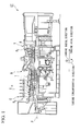
- Fig. 1 is a half cross-sectional diagram which shows a brief constitution of the gas turbine GT according to the first embodiment of the present invention.
- the gas turbine GT is provided with a compressor C, a plurality of combustors B and a turbine T.
- the compressor C produces compressed air c.
- the combustor B supplies a fuel to the compressed air c supplied from the compressor C to produce a combustion gas g.
- the turbine T obtains rotation power from the combustion gas g supplied from the combustor B.
- a rotor R C of the compressor C and a rotor R T of the turbine T are coupled to the respective axial ends and extend coaxially with a turbine shaft (axis line) P.
- turbine axial direction a direction in which the turbine shaft P extends
- axial direction A circumferential direction of the turbine shaft P
- turbine circumferential direction A circumferential direction of the turbine shaft P
- radial direction A radial direction of the turbine shaft P is referred to as “turbine radial direction” or “radial direction.”
- the compressor C is provided with a vane row 2 and a blade row 3.
- the vane row 2 and the vane row 3 are alternately disposed inside a compressor casing 1 in the turbine axial direction.
- the vane row 2 and the blade row 3 are counted in set of a pair as one stage.
- the vane row 2 of each stage is installed by being fixed to the compressor casing 1 side. Then, the vane row 2 of each stage is structured such that a plurality of vanes 4 extending from the compressor casing 1 to the rotor R C side are arrayed annularly in the turbine circumferential direction.
- the blade row 3 of each stage is installed by being fixed to the rotor R C side. Then, the blade row 3 of each stage is structured such that a plurality of blades 5 extending from the rotor R C side to the compressor casing 1 side are arrayed annularly in the turbine circumferential direction.
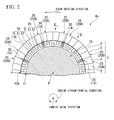
- Fig. 2 is a cross-sectional diagram taken along the line I to I of Fig. 1 .
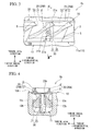
- Fig. 3 is an arrow view taken along the line II to II in Fig. 2 .
- Fig. 4 is a cross-sectional diagram taken along the line III to III of Fig. 3 .
- the rotor R C is provided with a rotation shaft body 10, a plurality of blade members (blade bodies) 20, each of which includes the above-described blade 5, and a plurality of blade fixing pieces 30.
- the rotation shaft body 10 is constituted so as to assume a shaft shape as a whole by disk-like members being stacked coaxially in the turbine axial direction.
- a blade groove 11 is formed at an outer circumference part 10A of the rotation shaft body 10. Blade members 20 are individually loaded into the blade groove 11 corresponding to the site at which the blade row 3 is disposed.
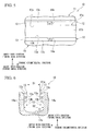
- Fig. 5 and Fig. 6 are views which show briefly a constitution of the rotation shaft body 10.
- Fig. 5 is an enlarged plan diagram of major parts and corresponds to Fig. 3 .
- Fig. 6 is an enlarged sectional diagram of the major parts and corresponds to Fig. 4 .
- each blade groove 11 extends in the turbine circumferential direction. Although not illustrated, each blade groove 11 is formed all across the circumference of the outer circumference part 10A.
- opening wall parts 13, 13 are formed on a blade opening 11a side.
- Each of the opening wall parts 13, 13 projects to the inside in the groove width direction from the groove opening 11a side of the blade groove 11. That is, as shown in Fig. 6 , a width dimension D1 on the groove opening 11a side of the blade groove 11 is set to be smaller than a width dimension D2 thereof on the groove bottom 11b side.
- the opening wall parts 13, 13 are provided with end faces 13a, 13a, each of which extends in the groove depth direction (turbine radial direction) of the blade groove 11 and opposes each other. These end faces 13a, 13a oppose each other in such a manner that a distance between them is the width dimension D1.
- lower parts 13b, 13b of the opening wall parts 13, 13 are chamfered.
- each of the opening wall parts 13, 13 is formed with an inclined face outward in the groove width direction by degrees from the groove opening 11a side to the groove bottom 11b side.
- the inclined face is formed in continuation with each of the end faces 13a, 13a and a lower part of each of the both side walls 12, 12.
- upper parts 13c, 13c of the opening wall parts 13, 13 are formed in a circular-arc shape so that an opening width gradually narrows from the outside to the inside in the groove width direction.
- Each of the opening wall parts 13, 13 extends on the whole circumference in the turbine circumferential direction (refer to Fig. 2 ). Further, the opening wall parts 13, 13 are provided with concaved portions (recessed parts) 14, 14 at a plurality of sites with intervals in the turbine circumferential direction.
- each of the concaved portions 14, 14 is formed in a groove shape and also extends in the groove depth direction (turbine radial direction) of the blade groove 11.
- the concaved portions 14, 14 communicatively connect a downside of the lower parts 13b, 13b of the opening wall parts 13, 13 and an upside of the upper parts 13c, 13c of the opening wall parts 13, 13.
- these concaved portions 14, 14 are formed in such a manner that a cross-sectional contour orthogonal to the groove depth direction of the blade groove 11 assumes a square.
- the concaved portions 14, 14 are also formed in such a manner that end faces 14a, 14a in the groove width direction assume a circular-arc shape.
- These concaved portions 14, 14 are formed so as to oppose each other in the groove width direction of the blade groove 11.
- a blade insertion hole 11c which opens widely so that a blade root 22 of the blade member 20 can be inserted is formed at a position different from positions where the concaved portions 14, 14 are formed.
- the blade root 22 of the blade member 20 will be described later by referring to Fig. 11 and Fig. 12 .
- the groove bottom 11b of the blade groove 11 is formed in a circular arc shape so as to be gradually increased in groove depth to inward in the groove width direction on a cross section orthogonal to the turbine circumferential direction.
- a platform 21 leading to the base end of the blade 5 and the blade root 22 leading to the platform 21 are formed from the outside to the inside in the turbine radial direction in the above-described order.
- the blade 5 is formed in a streamline shape so as to be orthogonal to the turbine radial direction. As shown in Fig. 3 , the blade 5 is also formed in such a shape that a distal end side thereof in the turbine radial direction is twisted around the turbine radial direction with respect to the base end side.
- the platform 21 extends so as to intersect the turbine radial direction and covers the blade groove 11. Further, the surface of the platform 21 leads to the base end of the blade 5.
- the platform 21 can be formed in a plate shape, for example.
- the platform 21 can be formed as a parallelogram when viewed from the outside to the inside in the turbine radial direction.
- an access hole 21b which penetrates in the turbine radial direction, as shown in Fig. 4 is defined by the end edges 21a of both the platforms 21 which are butted with each other in the turbine circumferential direction as shown in Fig. 3 .
- the blade root 22 leads to the back of the platform 21 and is formed so as to gradually increase a dimension in the turbine axial direction to inside in the turbine radial direction on a cross section (not illustrated) orthogonal to the turbine circumferential direction.
- the blade root 22 is fitted into the groove bottom 11b side of the blade groove 11 shown in Fig. 6 .
- the blade root 22 allows one part of both side-parts thereof in the turbine axial direction to run along the lower parts 13b, 13b of the opening wall parts 13, 13.
- the blade fixing piece 30 is arranged between one set of adjacent two blade members 20 (20A, 20B) in the turbine circumferential direction inside the blade groove 11.
- a plurality (for example, eight) of the blade fixing pieces 30 are disposed at the positions corresponding to the concaved portions 14, 14 in the turbine circumferential direction.
- a predetermined number of blade members 20 are positioned between adjacent two blade fixing pieces 30 in the circumferential direction.
- the blade fixing pieces 30 may not be disposed at an equal interval.
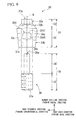
- Fig. 7 is an exploded diagram when the blade fixing piece 30 is viewed from the front.
- Fig. 8 is a plan diagram which shows the blade fixing piece 30.
- Fig. 9 is an exploded diagram when the blade fixing piece 30 is viewed from the side face.
- the blade fixing piece 30 is provided with a piece main body 31 and an advance-retract axle 35.
- the piece main body 31 is a member having a through hole 31 a formed on a member axis line Q of the blade fixing piece 30.
- the piece main body 31 is provided with a stepped cylinder part 32 and a body wall part 33.
- the stepped cylinder part 32 is formed at one end of the member axis-line direction in which the member axis line Q extends (turbine radial direction).
- the body wall part 33 is formed at the other side of the member axis-line direction.
- the stepped cylinder part 32 is provided with a neck part 32a and a shoulder part 32b.
- the neck part 32a is formed so as to be constant in diameter at one side in the member axis-line direction.
- the shoulder part 32b is formed in continuation with the neck part 32a and formed in such a shape that a part which gradually increases in diameter from one end to the other end in the member axis-line direction is set in two stages.
- the body wall part 33 is formed in continuation with the shoulder part 32b. Then, the body wall part 33 is formed in a flat hexagon shape in which a cross sectional shape orthogonal to the member axis-line direction shown in Fig. 8 is set in such a manner that the body thickness is thinner than the body width.
- This body wall part 33 as shown in Fig. 7 , is provided with a tapered part 33a formed in continuation with the shoulder part 32b and a bottom part 33b formed in continuation with the tapered part 33a at the other side in the member axis-line direction.
- the tapered part 33a gradually increases so that cross sectional area of the flat hexagon enlarges the body width, as shown in Fig. 8 , from one side to the other side in the member axis-line direction, as shown in Fig. 7 .
- the bottom part 33b is formed in such a manner that the body width is substantially constant in dimension. Further, the bottom part 33b is formed so that corners of the both ends 33b1 of the bottom face in the body width direction are chamfered.
- Tapered faces 33c, 33c which increase in width from one side to the other side in the member axis-line direction extend on both sides in the body width direction of the tapered part 33a of the body wall part 33.
- the tapered faces 33c, 33c are formed so that a curvature thereof is equal to a curvature of the lower parts 13b, 13b of the opening wall parts 13, 13.
- Projection walls (projected parts) 33d, 33d projecting in the member axis-line direction and in the body width direction are formed respectively at the centers in the thickness direction of the tapered faces 33c, 33c.
- Each of the projection walls 33d, 33d is formed in a triangular prism shape in which the bottom face assumes a right isosceles triangle with the perpendicular direction of the bottom face being directed to the body thickness direction.
- Each of the projection walls 33d, 33d causes the square face 33d1, which is one of two square faces 33d1, 33d2 formed substantially equal in dimension, to intersect with the member axis-line direction. Then, each of the projection walls 33d, 33d causes the other square face 33d2 to intersect with the body width direction of the piece main body 31. Further, corner edges of the square face 33d2 are chamfered.
- the above-described through hole 31a is formed at the body wall part 33 so as to be constant in diameter. Further, the through hole 31a is formed at the stepped cylinder part 32 so as to be reduced in diameter in two stages. An internal thread part 31b is formed at a site of the body wall part 33 which is formed constant in diameter.
- the advance-retract axle 35 is provided with a shaft part 36 and an external thread part 37.
- the shaft part 36 is formed at one side in the member axis-line direction so as to be relatively small in diameter.
- the external thread part 37 is formed at the other side in the member axis-line direction so as to be relatively large in diameter, with the outer circumference face thereof being threaded.
- An engagement groove 36b with which a tool such as a slotted screwdriver can be engaged is formed at an end face 36a which is one side of the shaft part 36 in the member axis-line direction.
- An end face 37a which is at the other side in the member axis-line direction of the external thread part 37 swells out to the other side of the member axis-line direction.
- the external thread part 37 is screwed into the internal thread part 31b of the piece main body 31 by the advance-retract axle 35.
- the advance-retract axle 35 is configured to be capable of being screwed toward the piece main body 31 in the member axis-line direction. Further, when the advance-retract axle 35 is screwed toward the other side in the member axis-line direction, the shaft part 36 is fitted into an opening of the through hole 31a of the stepped cylinder part 32.
- the internal thread part 31b of the advance-retract axle 35 is screwed into the internal thread part 31 b of the piece main body 31, thereby constituting a movable mechanism 39 which allows the piece main body 31 to advance and retract with respect to the groove bottom 11b of the blade groove 11 in the turbine radial direction.
- Fig. 10 is a perspective diagram which shows a usage state of the blade fixing piece 30.
- the blade member 20 is not illustrated.
- the blade fixing piece 30 directs the member axis line Q of the blade fixing piece 30 in the turbine radial direction (blade depth direction) and also directs the body width direction in the turbine axial direction (groove width direction) at a site where each of the concaved portions 14, 14 is formed. Then, the blade fixing piece 30 is restricted from being displaced in the turbine circumferential direction with respect to the blade groove 11 by fitting the projection walls 33d, 33d of the piece main body 31 into the concaved portions 14, 14.
- the blade fixing piece 30 causes the end face 37a of the advance-retract axle 35 to make a point contact with the groove bottom 11b of the blade groove 11. Then, the blade fixing piece 30 is restricted in the turbine radial direction by receiving a reaction force that the advance-retract axle 35 receives from the groove bottom 11b of the blade groove 11 and a reaction force that the tapered faces 33c, 33c receive from the lower parts 13b, 13b of the opening wall parts 13, 13.
- the blade root 22 of the blade member 20 shown in Fig. 2 is inserted into the blade insertion hole 11c of the blade groove 11 shown in Fig. 11 and Fig. 12 .
- the blade root 22 is fitted into a lower side of the blade groove 11 by the blade member 20 being caused to slide in the turbine circumferential direction.
- the blade member 20 is caused to slide in the turbine circumferential direction in a state where the blade root 22 is fitted into the lower side of the blade groove 11.
- This operation is repeated for every blade member 20, thereby loading a predetermined number of blade members 20 into the blade groove 11.
- a blade member 20 of the predetermined number of blade members 20, which is to be loaded last is one of the above-described blade members 20A, 20B (for example, the blade member 20B).
- the blade fixing piece 30 is inserted into the blade insertion hole 11c of the blade groove 11.
- the advance-retract axle 35 is set for its projection extent in such a manner that a gap is formed between the projection walls 33d, 33d on both sides of the piece main body 31 and the lower parts 13b, 13b of the opening wall parts 13, 13 in a state where the end face 37a of the advance-retract axle 35 is caused to make a point contact at least with the groove bottom 11b of the blade groove 11.
- the blade fixing piece 30 is caused to slide in the turbine circumferential direction.
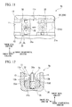
- the other of the blade members 20A, 20B (for example, the blade member 20B) is loaded into the blade insertion hole 11c of the blade groove 11 shown in Fig. 11 and Fig. 12 .
- the access hole 21b is defined by both end edges 21a which are butted with each other in the turbine circumferential direction of the blade members 20A, 20B. Further, as shown in Fig. 13 , the end face 36a of the advance-retract axle 35 is exposed from the access hole 21b.
- the blade fixing piece 30 inserted into the blade groove 11 is caused to slide in the turbine circumferential direction inside the blade groove 11 together with the blade member 20.
- corner edges of the square face 33d1 on the projection wall 33d of the body wall part 33 and both ends 33b1 of the bottom part 33b of the piece main body 31 are chamfered, and the end face 37a of the shaft part 36 swells out. Therefore, the blade fixing piece 30 slides smoothly on an inner surface of the blade groove 11.
- a tool K is engaged with the end face 36a of the shaft part 36, thereby causing the advance-retract axle 35 to move rotationally.
- the advance-retract axle 35 is screwed inward in the turbine radial direction into the piece main body 31.
- the piece main body 31 undergoes a relative displacement outward in the turbine radial direction so as to be spaced away from the groove bottom 11b.
- the projection walls 33d, 33d are fitted into the concaved portions 14, 14, and the tapered faces 33c, 33c come into contact with the lower parts 13b, 13b of the opening wall parts 13, 13.
- the advance-retract axle 35 is caused to move rotationally, thereby restricting a relative displacement between the piece main body 31 and the advance-retract axle 35.
- the advance-retract axle 35 receives a reaction force from the groove bottom 11b of the blade groove 11, and also the tapered faces 33c, 33c receive a reaction force from the lower parts 13b, 13b of the opening wall parts 13, 13.
- the blade fixing piece 30 is restricted from being displaced with respect to the blade groove 11.
- the projection walls 33d, 33d of the blade fixing piece 30 interfere with the concaved portions 14, 14 of the opening wall parts 13, 13, thereby restricting the blade fixing piece 30 in the turbine circumferential direction.
- the advance-retract axle 35 receives the reaction force from the groove bottom 11b of the blade groove 11, and also the tapered faces 33c, 33c receive the reaction force from the lower parts 13b, 13b of the opening wall parts 13, 13.
- the blade fixing piece 30 is fixed in the turbine radial direction.
- the outer circumference part 10A of the rotation shaft body 10 is exposed to a high-temperature working fluid (compressed air) to cause a difference in temperature between the inside and the outside of the rotation shaft body 10.
- a differential thermal expansion between the outside and the inside of the rotation shaft body 10 will cause a thermal stress.
- stress is less likely to concentrate on the groove bottom. Therefore, for example, it would be hard to cause a crack on the groove bottom 11b of the blade groove 11 even if start-up of the gas turbine GT is repeated.
- the concaved portions 14, 14 are positioned on the surface of the rotation shaft body 10, they are more easily increased in temperature than the groove bottom 11b. Further, a difference in temperature is hard to take place on the surface of the rotation shaft body 10, and thermal stress is relatively small. As a result, even when stress is concentrated on the concaved portions 14, 14, it is quite short in duration of time and the stress is relatively low in intensity. Therefore, cracks are hard to occur at the concaved portions 14, 14 which are structurally discontinued parts.
- the projection walls 33d, 33d are formed on the blade fixing piece 30, and the concaved portions 14, 14 which are fitted to the projection walls 33d, 33d are formed at the opening wall parts 13, 13 of the blade groove 11. Therefore, a relative displacement in the turbine circumferential direction of the blade member 20 with respect to the blade groove 11 is restricted by interference between the projection walls 33d, 33d and the concaved portions 14, 14. As a result, stress is hard to concentrate on the groove bottom 11b of the blade groove 11, thus making it possible to avoid the occurrence of cracks on the groove bottom 11b of the blade groove 11.
- a conventional rotor structure when a crack occurs on the groove bottom 11b of the blade groove 11 in a state where the blade member 20 is assembled to the rotation shaft body 10, it is difficult to find the crack during ordinary maintenance and inspection. As a result, the crack progresses excessively or the rotation shaft body 10 is broken by the crack, thus resulting in the fear that it may be necessary to stop operation of the compressor C into which the rotation shaft body 10 has been assembled. Further, the conventional rotor structure is also inferior in maintainability because even when a crack occurring on the groove bottom 11b of the blade groove 11 is found, it is difficult to repair the rotation body unless the assembled blade member 20 is detached.
- the blade fixing piece 30 in a state where fitting between the projection walls 33d, 33d and the concaved portions 14, 14 is cancelled, the blade fixing piece 30 is allowed to slide on the blade groove 11 in the turbine circumferential direction. Thereby, when assembling the blade member 20 and the blade fixing piece 30 to the rotation shaft body 10, the blade fixing piece 30 is caused to slide on the groove bottom 11b side of the blade groove 11 and can be arranged at a desired position. It is, thereby, possible to improve the workability of the process in which the blade members 20 and the blade fixing pieces 30 are assembled to the rotation shaft body 10.
- the projection walls 33d, 33d projecting from the tapered faces 33c, 33c in the turbine radial direction and in the turbine axial direction are fitted into the concaved portions 14, 14 extending in the turbine radial direction.
- the movable mechanism 39 causes the piece main body 31 on which the projection walls 33d, 33d are formed to advance and retract with respect to the groove bottom 11b of the blade groove 11, thereby the projection walls 33d, 33d and the concaved portions 14, 14 can be removably fit. Therefore, the projection walls 33d, 33d and the concaved portions 14, 14 can be removably fitted easily. It is, thereby, possible to improve the workability of assembling the blade members 20 and the blade fixing pieces 30 to the rotation shaft body 10.
- the advance-retract axle 35 can be screwed to the groove bottom 11b of the blade groove 11.
- the piece main body 31 is caused to advance and retract with respect to the groove bottom 11b of the blade groove 11 accurately and easily in a relatively simple constitution.
- the end face 36a on which the engagement groove 36b has been formed is exposed outside from the access hole 21b.
- the tool K such as a slotted screwdriver can be easily engaged therewith and also the advance-retract axle 35 is caused to move rotationally more easily. Thereby, it is possible to displace the advance-retract axle 35 quite easily.
- the end face 37a of the advance-retract axle 35 swells out to the groove bottom 11b of the blade groove 11. Thereby, the end face 37a of the advance-retract axle 35 on which the external thread part 37 has been formed is caused to make a point contact with the groove bottom 11b of the blade groove 11.
- the end face 37a of the advance-retract axle 35 on which the external thread part 37 has been formed is prevented from making a partial contact with the groove bottom 11b of the blade groove 11 and caused to reliably make a point contact therewith.
- the piece main body 31 is caused to more reliably advance and retract with respect to the groove bottom 11b of the blade groove 11.
- the groove bottom 11b of the blade groove 11 is formed so as to be recessed in a circular-arc shape on a cross section orthogonal to the turbine circumferential direction.
- the end face 37a of the advance-retract axle 35 is caused to swell out to the groove bottom 11b, by which the end face 37a is caused to more reliably make a point contact with the groove bottom 11b.
- the blade fixing piece 30 is provided with the tapered faces 33c, 33c which are in contact with the opening wall parts 13, 13 of the blade groove 11 from the groove bottom 11b of the blade groove 11. It is, thereby, possible to successfully restrict the blade fixing piece 30 in the turbine radial direction.
- each of the tapered faces 33c, 33c is formed in such a shape along each of the lower parts 13b, 13b of the opening wall parts 13, 13.
- various sites of the tapered faces 33c, 33c can be pressed uniformly to the lower parts 13b, 13b.
- the various sites of the tapered faces 33c, 33c receive a uniform reaction force from the lower parts 13b, 13b. It is, therefore, possible to restrict more reliably the blade fixing piece 30 in the turbine radial direction.
- the blade fixing piece 30 is provided with the projection walls 33d, 33d, and the concaved portions 14, 14 are formed at the opening wall parts 13, 13 of the blade groove 11. It is, therefore, possible to avoid the occurrence of cracks on the groove bottom 11b of the blade groove 11 in a relatively simple constitution.
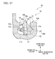
- Fig. 17 is a sectional diagram of major parts which shows a brief constitution of a blade fixing piece 30A according to the second embodiment of the present invention.
- the two projection walls 33d, 33d are formed on the tapered faces 33c, 33c of the blade fixing piece 30.
- the blade fixing piece 30A of the second embodiment no projection walls 33d, 33d are provided, and a screw member (projected part) 33g is provided in a projecting manner on one tapered face 33c of the tapered faces 33c, 33c in the turbine axial direction.
- the two concaved portions 14, 14 are formed at the opening wall parts 13, 13 of the blade groove 11.
- a concaved portion 14 is formed only at one of the opening wall parts 13 in the turbine axial direction.
- the same effect as that of the above-described first embodiment can be obtained.
- various design requirements can be met by using the screw member 33g which is separate from the blade fixing piece 30A according to the constitution of the present embodiment.
- the screw member 33g can be exchanged without detaching the blade fixing piece 30A from the blade groove 11. Therefore, repairs can be done quickly, and operation of the compressor C can be thereby restored immediately.
- a groove sectional contour is defined by the opening wall parts 13, 13 and the groove bottom 11b having a circular-arc cross section.
- the width dimension of the groove opening 11a side of the blade groove 11 is set to be smaller than the width dimension of the groove bottom 11b side of the blade groove 11, there may be adopted another groove sectional contour.
- the opening wall parts 13, 13 may be formed in a rectangular shape when viewed from the cross section, or the groove bottom 11b may be formed in the shape of a flat face.
- the projection walls 33d formed at the blade fixing piece 30 and the concaved portions 14, 14 formed at the opening wall parts 13, 13 are caused to be fitted.
- recessed parts are formed at the blade fixing piece 30, projected parts are formed at the opening wall parts 13, 13, and they are fitted with each other.
- the present invention is applied to the blade 5 of the compressor C.
- the present invention may be, however, applied to the blade of the turbine T.
- the present invention is applied to a gas turbine.
- the present invention may be applied to other rotary machines such as a steam turbine.
Landscapes
- Engineering & Computer Science (AREA)
- Mechanical Engineering (AREA)
- General Engineering & Computer Science (AREA)
- Turbine Rotor Nozzle Sealing (AREA)
- Structures Of Non-Positive Displacement Pumps (AREA)
Abstract
Description
- The present invention relates to a rotor structure. Priority is claimed on Japanese Patent Application No.
2011-059706 filed on March 17, 2011 - As is well known, in a rotary machine, typical examples of which are a compressor and a turbine, a rotor having a plurality of blades arrayed on an outer circumference of a rotation shaft body in a circumferential direction is used.
- For example, in Patent Document 1, a structure such that many blades are embedded in a blade groove bored on an outer circumference in a circumferential direction of a rotor of a rotary machine is adopted. In Patent Document 1, a blade fixing piece is fitted between the blade roots of adjacent two blades. Then, in Patent Document 1, a bolt is screwed into a threaded hole formed at the center in a radial direction of the blade fixing piece. On the other hand, a round hole is bored on a bottom face of the blade groove, and a lower end of the bolt is fitted into the round hole, thereby restricting displacement of the blades in the circumferential direction.
- Patent Document 1: Japanese Published Unexamined Utility Model Application, First Publication No.
Hei-3-25801 - However, in the conventional technology, an inner wall part of the round hole is a structurally discontinuous part. Thus, stress concentrates in the vicinity of the round hole and cracks may occur.
- The present invention has been made in view of the above-described situation, an object of which is to prevent the occurrence of cracks on a groove bottom of a blade groove.
- In order to attain the above object, the present invention has adopted the following means.
- According to a first aspect of the present invention, a rotor structure includes a rotation shaft body in which a blade groove is formed at an outer circumference part of the rotation shaft body rotating around an axis line and extends in a circumferential direction of the axis line, and a width dimension of a groove opening side of the blade groove is set to be smaller than a width dimension of a groove bottom side of the blade groove, and a plurality of blade bodies which are arrayed at the outer circumference part of the rotation shaft body in the circumferential direction and have blade roots fitted into the blade groove respectively. In the rotor structure, a blade fixing piece is installed so as to be positioned between at least one set of adjacent two blade bodies in the circumferential direction inside the blade groove, and one of an opening wall part of the groove opening side of the blade groove and the blade fixing piece is provided with a projected part, and the other of them is provided with a recessed part which is fitted to the projected part.
- In the rotor structure according to the first aspect of the present invention, one of an opening wall part of the blade groove and the blade fixing piece is provided with the projected part, while the other of them is provided with the recessed part which is fitted to the projected part. Thus, a relative displacement of the blade body with respect to the blade groove in the circumferential direction is restricted by interference of the projected part with the recessed part. Thereby, stress is hard to concentrate on the groove bottom of the blade groove, thus making it possible to avoid cracks on the groove bottom of the blade groove.
- In a conventional rotor structure, when a crack occurs on a groove bottom of a blade groove in a state where a blade body is assembled to a rotation shaft body, it is difficult to find the crack during ordinary maintenance and inspection. As a result, the crack may progress excessively or break the rotation shaft body, which may require stopping operation of an apparatus into which the rotation shaft body has been assembled. Further, even when a crack occurring on the groove bottom of the blade groove is found, it is difficult to repair unless the blade body having being assembled is detached. Thus, the conventional rotor structure is also inferior in maintainability.
- However, as described above, with the rotor structure according to the first aspect of the present invention, there is no possibility that a crack occurs on the groove bottom of the blade groove. Further, even if a crack has occurred on the opening wall part of the blade groove, the site of the crack is positioned on the surface of the rotation shaft body. Thus, the crack can be found easily. As a result, it is possible to prevent breakage of the rotation shaft body resulting from the crack. It is, thereby, possible to operate stably and continuously an apparatus into which the rotation shaft body has been assembled. Still further, since the site of the crack occurs on the surface of the rotation shaft body, repairs can be done relatively easily.
- According to a second aspect of the present invention, the blade fixing piece is allowed to slide in the circumferential direction in the blade groove in a state where fitting of the projected part into the recessed part is cancelled.
- In the rotor structure according to the second aspect of the present invention, the blade fixing piece is allowed to slide in the circumferential direction in the blade groove in a state where fitting of the projected part into the recessed part is cancelled. Thus, when the blade body and the blade fixing piece are assembled to the rotation shaft body, a piece main body can be caused to slide on the groove bottom of the blade groove and arranged at a desired position.
- Thereby, it is possible to improve workability of assembling the blade body and the blade fixing piece to the rotation shaft body.
- According to a third aspect of the present invention, the projected part projects in a radial direction of the axis line and the recessed part extends in the radial direction.
- In the rotor structure according to the third aspect of the present invention, the projected part which projects in the radial direction is fitted into the recessed part which extends in the radial direction. It is, thereby, possible to reliably restrict the blade fixing member in the circumferential direction.
- According to a fourth aspect of the present invention, the blade fixing piece includes a piece main body on which the projected part or the recessed part is formed, and a displacement mechanism which causes the piece main body to advance and retract with respect to the groove bottom of the blade groove in the radial direction of the axis line to allow the projected part to removably fit to the recessed part.
- In the rotor structure according to the fourth aspect of the present invention, a movable mechanism is configured to cause the piece main body on which the projected part or the recessed part is formed to advance and retract with respect to the groove bottom of the blade groove to allow the projected part to removably fit to the recessed part. Thus, the projected part can be removably fitted to the recessed part easily and accurately. It is, thereby, possible to improve workability when the blade body and the blade fixing piece are assembled to the rotation shaft body.
- According to a fifth aspect of the present invention, the displacement mechanism is provided with a through hole which penetrates through the piece main body in the radial direction and has at least partially an internal thread part, and an advance-retract axle which has at least partially an external thread part screwed with the internal thread part and can be screwed to the groove bottom of the blade groove.
- In the rotor structure according to the fifth aspect of the present invention, the advance-retract axle can be screwed to the groove bottom of the blade groove. Therefore, the piece main body is caused to advance and retract relative to the groove bottom of the blade groove accurately and easily in a relatively simple constitution.
- According to a sixth aspect of the present invention, an end face of the advance-retract axle that faces the groove bottom of the blade groove swells out to the groove bottom of the blade groove.
- In the rotor structure according to the sixth aspect of the present invention, the end face of the advance-retract axle swells out to the groove bottom of the blade groove. Therefore, the end face of the advance-retract axle can be caused to make a point contact with the groove bottom of the blade groove. The end face of the advance-retract axle is, thereby, prevented from making partial contact with the groove bottom of the blade groove and reliably caused to make a point contact therewith. As a result, the piece main body can be caused to more reliably advance and retract relative to the groove bottom of the blade groove.
- According to a seventh aspect of the present invention, the blade fixing piece includes a contact part which is in contact with the opening wall part of the blade groove from the groove bottom of the blade groove.
- In the rotor structure according to the seventh aspect of the present invention, the blade fixing piece includes the contact part which is in contact with the opening wall part of the blade groove from the groove bottom of the blade groove. Therefore, it is possible to successfully restrict the blade fixing piece in the radial direction.
- According to an eighth aspect of the present invention, the blade fixing piece is provided with a projection wall as the projected part which projects in the radial direction of the axis line at least on one side in the width direction of the blade groove, and the opening wall part of the blade groove is provided with a concaved portion as the recessed part which extends in the radial direction at least on one side in the width direction of the blade groove.
- In the rotor structure according to the eighth aspect of the present invention, the blade fixing piece is provided with the projection wall, and the opening wall part of the blade groove is provided with the concaved portion. It is, thus, possible to avoid the occurrence of cracks on the groove bottom of the blade groove in a relatively simple constitution.
- According to a ninth aspect of the present invention, the blade fixing piece is provided with a screw member as the projected part which projects in the radial direction of the axis line at least on one side in the width direction of the blade groove, and the opening wall part of the blade groove is provided with a concaved portion as the recessed part which extends in the radial direction at least on one side in the width direction of the blade groove.
- In the rotor structure according to the ninth aspect of the present invention, the blade fixing piece is provided with the screw member, and the opening wall part of the blade groove is provided with the concaved portion. Therefore, it is possible to avoid the occurrence of cracks on the groove bottom of the blade groove in a relatively simple constitution. It is also possible to meet various design requirements.
- In the rotor structure according to these aspects of the present invention, it is possible to prevent the occurrence of cracks on the groove bottom of the blade groove.
-
-
Fig. 1 is a half cross-sectional diagram which shows a brief constitution of a gas turbine GT according to a first embodiment of the present invention. -
Fig. 2 is a cross-sectional diagram taken along the line I to I ofFig. 1 . -
Fig. 3 is an arrow view taken along the line II to II ofFig. 2 . -
Fig. 4 is a cross-sectional diagram taken along the line III to III ofFig. 3 . -
Fig. 5 is an enlarged plan diagram of major parts which shows arotation shaft body 10 according to the first embodiment of the present invention and corresponds toFig. 3 . -
Fig. 6 is an enlarged sectional diagram of the major parts which shows therotation shaft body 10 according to the first embodiment of the present invention and corresponds toFig. 4 . -
Fig. 7 is an exploded diagram when ablade fixing piece 30 according to the first embodiment of the present invention is viewed from the front and in which a piecemain body 31 is shown in a half cross section. -
Fig. 8 is a plan diagram which shows theblade fixing piece 30 according to the first embodiment of the present invention. -
Fig. 9 is an exploded diagram when theblade fixing piece 30 according to the first embodiment of the present invention is viewed from the side face. -
Fig. 10 is a perspective diagram which shows a usage state of theblade fixing piece 30 according to the first embodiment of the present invention. Ablade member 20 is not illustrated inFig. 10 . -
Fig. 11 is an explanation drawing of a first action according to the first embodiment of the present invention and corresponds toFig. 3 . -
Fig. 12 is an explanation drawing of a second action according to the first embodiment of the present invention and corresponds toFig. 4 . -
Fig. 13 is an explanation drawing of a third action according to the first embodiment of the present invention and corresponds toFig. 3 . -
Fig. 14 is an explanation drawing of a fourth action according to the first embodiment of the present invention and corresponds toFig. 4 . -
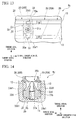
Fig. 15 is an explanation drawing of a fifth action according to the first embodiment of the present invention and corresponds toFig. 3 . -
Fig. 16 is an explanation drawing of a sixth action according to the first embodiment of the present invention and corresponds toFig. 4 . -
Fig. 17 is a sectional diagram of major parts which shows a brief constitution of ablade fixing piece 30A according to a second embodiment of the present invention. - Hereinafter, a description will be given for embodiments of the present invention by referring to drawings.
-
Fig. 1 is a half cross-sectional diagram which shows a brief constitution of the gas turbine GT according to the first embodiment of the present invention. As shown inFig. 1 , the gas turbine GT is provided with a compressor C, a plurality of combustors B and a turbine T. The compressor C produces compressed air c. The combustor B supplies a fuel to the compressed air c supplied from the compressor C to produce a combustion gas g. The turbine T obtains rotation power from the combustion gas g supplied from the combustor B. - In the gas turbine GT, a rotor RC of the compressor C and a rotor RT of the turbine T are coupled to the respective axial ends and extend coaxially with a turbine shaft (axis line) P.
- In the following description, a direction in which the turbine shaft P extends is referred to as "turbine axial direction" or "axial direction." A circumferential direction of the turbine shaft P is referred to as "turbine circumferential direction" or "circumferential direction." A radial direction of the turbine shaft P is referred to as "turbine radial direction" or "radial direction."
- The compressor C is provided with a
vane row 2 and ablade row 3. Thevane row 2 and thevane row 3 are alternately disposed inside a compressor casing 1 in the turbine axial direction. Thevane row 2 and theblade row 3 are counted in set of a pair as one stage. - The
vane row 2 of each stage is installed by being fixed to the compressor casing 1 side. Then, thevane row 2 of each stage is structured such that a plurality ofvanes 4 extending from the compressor casing 1 to the rotor RC side are arrayed annularly in the turbine circumferential direction. - The
blade row 3 of each stage is installed by being fixed to the rotor RC side. Then, theblade row 3 of each stage is structured such that a plurality ofblades 5 extending from the rotor RC side to the compressor casing 1 side are arrayed annularly in the turbine circumferential direction. -
Fig. 2 is a cross-sectional diagram taken along the line I to I ofFig. 1 .Fig. 3 is an arrow view taken along the line II to II inFig. 2 .Fig. 4 is a cross-sectional diagram taken along the line III to III ofFig. 3 . - As shown in
Fig. 2 , the rotor RC is provided with arotation shaft body 10, a plurality of blade members (blade bodies) 20, each of which includes the above-describedblade 5, and a plurality ofblade fixing pieces 30. - As shown in
Fig. 1 orFig. 2 , therotation shaft body 10 is constituted so as to assume a shaft shape as a whole by disk-like members being stacked coaxially in the turbine axial direction. As shown inFig. 2 andFig. 4 , ablade groove 11 is formed at anouter circumference part 10A of therotation shaft body 10.Blade members 20 are individually loaded into theblade groove 11 corresponding to the site at which theblade row 3 is disposed. -
Fig. 5 and Fig. 6 are views which show briefly a constitution of therotation shaft body 10.Fig. 5 is an enlarged plan diagram of major parts and corresponds toFig. 3 .Fig. 6 is an enlarged sectional diagram of the major parts and corresponds toFig. 4 . - As shown in
Fig. 5 , eachblade groove 11 extends in the turbine circumferential direction. Although not illustrated, eachblade groove 11 is formed all across the circumference of theouter circumference part 10A. On bothside walls blade groove 11, openingwall parts blade opening 11a side. Each of the openingwall parts groove opening 11a side of theblade groove 11. That is, as shown inFig. 6 , a width dimension D1 on thegroove opening 11a side of theblade groove 11 is set to be smaller than a width dimension D2 thereof on thegroove bottom 11b side. - As shown in
Fig. 6 , the openingwall parts blade groove 11 and opposes each other. These end faces 13a, 13a oppose each other in such a manner that a distance between them is the width dimension D1. Further,lower parts wall parts wall parts groove opening 11a side to thegroove bottom 11b side. The inclined face is formed in continuation with each of the end faces 13a, 13a and a lower part of each of the bothside walls upper parts wall parts - Each of the opening
wall parts Fig. 2 ). Further, the openingwall parts - As shown in
Fig. 5 and Fig. 6 , each of theconcaved portions blade groove 11. Theconcaved portions lower parts wall parts upper parts wall parts Fig. 5 , theseconcaved portions blade groove 11 assumes a square. Theconcaved portions - These
concaved portions blade groove 11. - In the opening
wall parts blade insertion hole 11c which opens widely so that ablade root 22 of theblade member 20 can be inserted is formed at a position different from positions where theconcaved portions blade root 22 of theblade member 20 will be described later by referring toFig. 11 and Fig. 12 . - As shown in
Fig. 6 , thegroove bottom 11b of theblade groove 11 is formed in a circular arc shape so as to be gradually increased in groove depth to inward in the groove width direction on a cross section orthogonal to the turbine circumferential direction. - As shown in
Fig. 2 , in theblade member 20, the above-describedblade 5, aplatform 21 leading to the base end of theblade 5 and theblade root 22 leading to theplatform 21 are formed from the outside to the inside in the turbine radial direction in the above-described order. - As shown in
Fig. 3 , theblade 5 is formed in a streamline shape so as to be orthogonal to the turbine radial direction. As shown inFig. 3 , theblade 5 is also formed in such a shape that a distal end side thereof in the turbine radial direction is twisted around the turbine radial direction with respect to the base end side. - As shown in
Fig. 3 , theplatform 21 extends so as to intersect the turbine radial direction and covers theblade groove 11. Further, the surface of theplatform 21 leads to the base end of theblade 5. Theplatform 21 can be formed in a plate shape, for example. Theplatform 21 can be formed as a parallelogram when viewed from the outside to the inside in the turbine radial direction. - Further, in two blade members 20 (20A, 20B) which sandwich the
blade fixing piece 30, anaccess hole 21b which penetrates in the turbine radial direction, as shown inFig. 4 , is defined by the end edges 21a of both theplatforms 21 which are butted with each other in the turbine circumferential direction as shown inFig. 3 . - As shown in
Fig. 2 , theblade root 22 leads to the back of theplatform 21 and is formed so as to gradually increase a dimension in the turbine axial direction to inside in the turbine radial direction on a cross section (not illustrated) orthogonal to the turbine circumferential direction. - The
blade root 22 is fitted into thegroove bottom 11b side of theblade groove 11 shown inFig. 6 . Theblade root 22 allows one part of both side-parts thereof in the turbine axial direction to run along thelower parts wall parts - As shown in
Fig. 2 , theblade fixing piece 30 is arranged between one set of adjacent two blade members 20 (20A, 20B) in the turbine circumferential direction inside theblade groove 11. In the present embodiment, a plurality (for example, eight) of theblade fixing pieces 30 are disposed at the positions corresponding to theconcaved portions blade fixing piece 30, a predetermined number ofblade members 20 are positioned between adjacent twoblade fixing pieces 30 in the circumferential direction. Theblade fixing pieces 30 may not be disposed at an equal interval. -
Fig. 7 is an exploded diagram when theblade fixing piece 30 is viewed from the front.Fig. 8 is a plan diagram which shows theblade fixing piece 30.Fig. 9 is an exploded diagram when theblade fixing piece 30 is viewed from the side face. - As shown in
Fig. 7 to Fig. 9 , theblade fixing piece 30 is provided with a piecemain body 31 and an advance-retractaxle 35. - As shown in
Fig. 7 andFig. 9 , the piecemain body 31 is a member having a throughhole 31 a formed on a member axis line Q of theblade fixing piece 30. The piecemain body 31 is provided with a steppedcylinder part 32 and abody wall part 33. The steppedcylinder part 32 is formed at one end of the member axis-line direction in which the member axis line Q extends (turbine radial direction). Thebody wall part 33 is formed at the other side of the member axis-line direction. - The stepped
cylinder part 32 is provided with aneck part 32a and ashoulder part 32b. Theneck part 32a is formed so as to be constant in diameter at one side in the member axis-line direction. Theshoulder part 32b is formed in continuation with theneck part 32a and formed in such a shape that a part which gradually increases in diameter from one end to the other end in the member axis-line direction is set in two stages. - As shown in
Fig. 7 andFig. 9 , thebody wall part 33 is formed in continuation with theshoulder part 32b. Then, thebody wall part 33 is formed in a flat hexagon shape in which a cross sectional shape orthogonal to the member axis-line direction shown inFig. 8 is set in such a manner that the body thickness is thinner than the body width. Thisbody wall part 33, as shown inFig. 7 , is provided with atapered part 33a formed in continuation with theshoulder part 32b and abottom part 33b formed in continuation with thetapered part 33a at the other side in the member axis-line direction. - The
tapered part 33a gradually increases so that cross sectional area of the flat hexagon enlarges the body width, as shown inFig. 8 , from one side to the other side in the member axis-line direction, as shown inFig. 7 . - As shown in
Fig. 7 , thebottom part 33b is formed in such a manner that the body width is substantially constant in dimension. Further, thebottom part 33b is formed so that corners of the both ends 33b1 of the bottom face in the body width direction are chamfered. -
Tapered faces tapered part 33a of thebody wall part 33. - As shown in
Fig. 10 , the tapered faces 33c, 33c are formed so that a curvature thereof is equal to a curvature of thelower parts wall parts - Each of the
projection walls projection walls projection walls main body 31. Further, corner edges of the square face 33d2 are chamfered. - The above-described through
hole 31a is formed at thebody wall part 33 so as to be constant in diameter. Further, the throughhole 31a is formed at the steppedcylinder part 32 so as to be reduced in diameter in two stages. Aninternal thread part 31b is formed at a site of thebody wall part 33 which is formed constant in diameter. - The advance-retract
axle 35 is provided with ashaft part 36 and anexternal thread part 37. Theshaft part 36 is formed at one side in the member axis-line direction so as to be relatively small in diameter. Theexternal thread part 37 is formed at the other side in the member axis-line direction so as to be relatively large in diameter, with the outer circumference face thereof being threaded. - An
engagement groove 36b with which a tool such as a slotted screwdriver can be engaged is formed at anend face 36a which is one side of theshaft part 36 in the member axis-line direction. - An
end face 37a which is at the other side in the member axis-line direction of theexternal thread part 37 swells out to the other side of the member axis-line direction. - The
external thread part 37 is screwed into theinternal thread part 31b of the piecemain body 31 by the advance-retractaxle 35. Then, the advance-retractaxle 35 is configured to be capable of being screwed toward the piecemain body 31 in the member axis-line direction. Further, when the advance-retractaxle 35 is screwed toward the other side in the member axis-line direction, theshaft part 36 is fitted into an opening of the throughhole 31a of the steppedcylinder part 32. - As described above, the
internal thread part 31b of the advance-retractaxle 35 is screwed into theinternal thread part 31 b of the piecemain body 31, thereby constituting amovable mechanism 39 which allows the piecemain body 31 to advance and retract with respect to thegroove bottom 11b of theblade groove 11 in the turbine radial direction. -
Fig. 10 is a perspective diagram which shows a usage state of theblade fixing piece 30. InFig. 10 , theblade member 20 is not illustrated. - As shown in
Fig. 10 , theblade fixing piece 30 directs the member axis line Q of theblade fixing piece 30 in the turbine radial direction (blade depth direction) and also directs the body width direction in the turbine axial direction (groove width direction) at a site where each of theconcaved portions blade fixing piece 30 is restricted from being displaced in the turbine circumferential direction with respect to theblade groove 11 by fitting theprojection walls main body 31 into theconcaved portions - Further, the
blade fixing piece 30 causes theend face 37a of the advance-retractaxle 35 to make a point contact with thegroove bottom 11b of theblade groove 11. Then, theblade fixing piece 30 is restricted in the turbine radial direction by receiving a reaction force that the advance-retractaxle 35 receives from thegroove bottom 11b of theblade groove 11 and a reaction force that the tapered faces 33c, 33c receive from thelower parts wall parts - Next, a description will be given for some steps of assembly of the rotor RC mainly by referring to
Fig. 11 to Fig. 16 . FromFig. 11 to Fig. 16 , illustration of theblade member 20 is omitted by indicating a contour of theplatform 21 with a dashed line. - First, the
blade root 22 of theblade member 20 shown inFig. 2 is inserted into theblade insertion hole 11c of theblade groove 11 shown inFig. 11 and Fig. 12 . Next, theblade root 22 is fitted into a lower side of theblade groove 11 by theblade member 20 being caused to slide in the turbine circumferential direction. Then, theblade member 20 is caused to slide in the turbine circumferential direction in a state where theblade root 22 is fitted into the lower side of theblade groove 11. This operation is repeated for everyblade member 20, thereby loading a predetermined number ofblade members 20 into theblade groove 11. In this instance, ablade member 20 of the predetermined number ofblade members 20, which is to be loaded last is one of the above-describedblade members blade member 20B). - As shown in
Fig. 11 and Fig. 12 , after the predetermined number ofblade members 20 are completely loaded into theblade groove 11, theblade fixing piece 30 is inserted into theblade insertion hole 11c of theblade groove 11. - As shown in
Fig. 12 , when theblade fixing piece 30 is inserted into theblade groove 11, theend face 36a of the advance-retractaxle 35 is positioned outside from the steppedcylinder part 32 in the turbine radial direction. Further, in theblade fixing piece 30, the extent of projection of the advance-retractaxle 35 from the piecemain body 31 is small. To be more specific, the advance-retractaxle 35 is set for its projection extent in such a manner that a gap is formed between theprojection walls main body 31 and thelower parts wall parts end face 37a of the advance-retractaxle 35 is caused to make a point contact at least with thegroove bottom 11b of theblade groove 11. - In this state, the
blade fixing piece 30 is caused to slide in the turbine circumferential direction. - After the
blade fixing piece 30 is caused to slide, the other of theblade members blade member 20B) is loaded into theblade insertion hole 11c of theblade groove 11 shown inFig. 11 and Fig. 12 . Accordingly, theaccess hole 21b is defined by bothend edges 21a which are butted with each other in the turbine circumferential direction of theblade members Fig. 13 , theend face 36a of the advance-retractaxle 35 is exposed from theaccess hole 21b. - Then, as shown in
Fig. 13 and Fig. 14 , theblade fixing piece 30 inserted into theblade groove 11 is caused to slide in the turbine circumferential direction inside theblade groove 11 together with theblade member 20. In this instance, corner edges of the square face 33d1 on theprojection wall 33d of thebody wall part 33 and both ends 33b1 of thebottom part 33b of the piecemain body 31 are chamfered, and theend face 37a of theshaft part 36 swells out. Therefore, theblade fixing piece 30 slides smoothly on an inner surface of theblade groove 11. - When the
blade fixing piece 30 arrives at theconcaved portions Fig. 15 , it is arranged so that theprojection walls blade fixing piece 30 overlap theconcaved portions - Then, as shown in
Fig. 16 , a tool K is engaged with theend face 36a of theshaft part 36, thereby causing the advance-retractaxle 35 to move rotationally. Thus, the advance-retractaxle 35 is screwed inward in the turbine radial direction into the piecemain body 31. When theend face 37a of the advance-retractaxle 35 makes a point contact with thegroove bottom 11b of theblade groove 11, the piecemain body 31 undergoes a relative displacement outward in the turbine radial direction so as to be spaced away from thegroove bottom 11b. - Further, when the piece
main body 31 is increased in relative displacement amount with respect to thegroove bottom 11b, theprojection walls concaved portions lower parts wall parts - In addition, the advance-retract
axle 35 is caused to move rotationally, thereby restricting a relative displacement between the piecemain body 31 and the advance-retractaxle 35. At this time, the advance-retractaxle 35 receives a reaction force from thegroove bottom 11b of theblade groove 11, and also the tapered faces 33c, 33c receive a reaction force from thelower parts wall parts - Accordingly, the
blade fixing piece 30 is restricted from being displaced with respect to theblade groove 11. - That is, the
projection walls blade fixing piece 30 interfere with theconcaved portions wall parts blade fixing piece 30 in the turbine circumferential direction. Then, the advance-retractaxle 35 receives the reaction force from thegroove bottom 11b of theblade groove 11, and also the tapered faces 33c, 33c receive the reaction force from thelower parts wall parts blade fixing piece 30 is fixed in the turbine radial direction. - After all the
blade members 20 are loaded into theblade groove 11, twoblade members 20 apart by a half pitch are positioned at theblade insertion hole 11c of theblade groove 11 shown inFig. 11 and Fig. 12 . Further, a spacer member is inserted between these twoblade members 20, thereby blocking theblade insertion hole 11c of theblade groove 11. - In the rotor RC formed as described above, displacement of the
blade member 20 in the turbine circumferential direction is restricted by theblade fixing piece 30. That is, theprojection walls blade fixing piece 30 interfere with theconcaved portions wall parts blade member 20 from being displaced in the turbine circumferential direction. - Here, during start-up of the gas turbine GT, for example, the
outer circumference part 10A of therotation shaft body 10 is exposed to a high-temperature working fluid (compressed air) to cause a difference in temperature between the inside and the outside of therotation shaft body 10. In this instance, a differential thermal expansion between the outside and the inside of therotation shaft body 10 will cause a thermal stress. However, since no structurally discontinuous part is formed on thegroove bottom 11b of theblade groove 11, stress is less likely to concentrate on the groove bottom. Therefore, for example, it would be hard to cause a crack on thegroove bottom 11b of theblade groove 11 even if start-up of the gas turbine GT is repeated. - Then, since the
concaved portions rotation shaft body 10, they are more easily increased in temperature than thegroove bottom 11b. Further, a difference in temperature is hard to take place on the surface of therotation shaft body 10, and thermal stress is relatively small. As a result, even when stress is concentrated on theconcaved portions concaved portions - Even if cracks occur on the
concaved portions concaved portions outer circumference part 10A of therotation shaft body 10. - As described above, according to the present embodiment, the
projection walls blade fixing piece 30, and theconcaved portions projection walls wall parts blade groove 11. Therefore, a relative displacement in the turbine circumferential direction of theblade member 20 with respect to theblade groove 11 is restricted by interference between theprojection walls concaved portions groove bottom 11b of theblade groove 11, thus making it possible to avoid the occurrence of cracks on thegroove bottom 11b of theblade groove 11. - In a conventional rotor structure, when a crack occurs on the
groove bottom 11b of theblade groove 11 in a state where theblade member 20 is assembled to therotation shaft body 10, it is difficult to find the crack during ordinary maintenance and inspection. As a result, the crack progresses excessively or therotation shaft body 10 is broken by the crack, thus resulting in the fear that it may be necessary to stop operation of the compressor C into which therotation shaft body 10 has been assembled. Further, the conventional rotor structure is also inferior in maintainability because even when a crack occurring on thegroove bottom 11b of theblade groove 11 is found, it is difficult to repair the rotation body unless the assembledblade member 20 is detached. - However, according to the present embodiment, there is no possibility that a crack occurs on the
groove bottom 11b of theblade groove 11. Further, even if a crack has occurred on theopening wall part blade groove 11, a site of the crack is positioned on the surface of theouter circumference 10A of therotation shaft body 10. Thus, the crack can be found easily. As a result, it is possible to prevent breakage of therotation shaft body 10 resulting from the crack. It is, thereby, possible to operate stably and continuously the compressor C into which therotation shaft body 10 has been assembled. Still further, since the site of the crack is positioned on the surface side of theouter circumference 10A of therotation shaft body 10, repairs can also be done relatively easily. - Further, according to the present embodiment, in a state where fitting between the
projection walls concaved portions blade fixing piece 30 is allowed to slide on theblade groove 11 in the turbine circumferential direction. Thereby, when assembling theblade member 20 and theblade fixing piece 30 to therotation shaft body 10, theblade fixing piece 30 is caused to slide on thegroove bottom 11b side of theblade groove 11 and can be arranged at a desired position. It is, thereby, possible to improve the workability of the process in which theblade members 20 and theblade fixing pieces 30 are assembled to therotation shaft body 10. - Further, according to the present embodiment, the
projection walls concaved portions projection walls concaved portions blade fixing piece 30 can be reliably restricted in the turbine circumferential direction. - Further, according to the present embodiment, the
movable mechanism 39 causes the piecemain body 31 on which theprojection walls groove bottom 11b of theblade groove 11, thereby theprojection walls concaved portions projection walls concaved portions blade members 20 and theblade fixing pieces 30 to therotation shaft body 10. - Further, according to the present embodiment, the advance-retract
axle 35 can be screwed to thegroove bottom 11b of theblade groove 11. Thereby, the piecemain body 31 is caused to advance and retract with respect to thegroove bottom 11b of theblade groove 11 accurately and easily in a relatively simple constitution. - Still further, according to the present embodiment, the
end face 36a on which theengagement groove 36b has been formed is exposed outside from theaccess hole 21b. Thereby, the tool K such as a slotted screwdriver can be easily engaged therewith and also the advance-retractaxle 35 is caused to move rotationally more easily. Thereby, it is possible to displace the advance-retractaxle 35 quite easily. - In addition, according to the present embodiment, the
end face 37a of the advance-retractaxle 35 swells out to thegroove bottom 11b of theblade groove 11. Thereby, theend face 37a of the advance-retractaxle 35 on which theexternal thread part 37 has been formed is caused to make a point contact with thegroove bottom 11b of theblade groove 11. - Thereby, the
end face 37a of the advance-retractaxle 35 on which theexternal thread part 37 has been formed is prevented from making a partial contact with thegroove bottom 11b of theblade groove 11 and caused to reliably make a point contact therewith. As a result, the piecemain body 31 is caused to more reliably advance and retract with respect to thegroove bottom 11b of theblade groove 11. - Further, in the present embodiment, in particular, the
groove bottom 11b of theblade groove 11 is formed so as to be recessed in a circular-arc shape on a cross section orthogonal to the turbine circumferential direction. However, theend face 37a of the advance-retractaxle 35 is caused to swell out to thegroove bottom 11b, by which theend face 37a is caused to more reliably make a point contact with thegroove bottom 11b. - Further, according to the present embodiment, the
blade fixing piece 30 is provided with the tapered faces 33c, 33c which are in contact with the openingwall parts blade groove 11 from thegroove bottom 11b of theblade groove 11. It is, thereby, possible to successfully restrict theblade fixing piece 30 in the turbine radial direction. - Still further, according to the present embodiment, each of the tapered faces 33c, 33c is formed in such a shape along each of the
lower parts wall parts lower parts lower parts blade fixing piece 30 in the turbine radial direction. - In addition, according to the present embodiment, the
blade fixing piece 30 is provided with theprojection walls concaved portions wall parts blade groove 11. It is, therefore, possible to avoid the occurrence of cracks on thegroove bottom 11b of theblade groove 11 in a relatively simple constitution. - Hereinafter, a description will be given for the second embodiment of the present invention by referring to drawings. In the following description and the drawings used for the description, constituents similar to those which have been already described will be given the same reference numerals, with overlapping descriptions being omitted.
-
Fig. 17 is a sectional diagram of major parts which shows a brief constitution of ablade fixing piece 30A according to the second embodiment of the present invention. - In the above-described first embodiment, the two
projection walls blade fixing piece 30. On the other hand, as shown inFig. 17 , in theblade fixing piece 30A of the second embodiment, noprojection walls face 33c of the tapered faces 33c, 33c in the turbine axial direction. - Further, in the above-described first embodiment, the two
concaved portions wall parts blade groove 11. On the other hand, in the second embodiment, at the openingwall parts concaved portion 14 is formed only at one of the openingwall parts 13 in the turbine axial direction. - In the constitution of the present embodiment, the same effect as that of the above-described first embodiment can be obtained. In addition, for example, even when it is difficult to secure the strength of the
projection wall 33d of the first embodiment or form theprojection walls blade fixing piece 30A, various design requirements can be met by using thescrew member 33g which is separate from theblade fixing piece 30A according to the constitution of the present embodiment. - Further, according to the present embodiment, even when the
screw member 33g is broken, thescrew member 33g can be exchanged without detaching theblade fixing piece 30A from theblade groove 11. Therefore, repairs can be done quickly, and operation of the compressor C can be thereby restored immediately. - The operation procedures shown in the above-described embodiments or various shapes and combinations of individual constituents are just examples. They may be modified in various ways on the basis of design requirements or the like in a scope not departing from the scope of the present invention.
- For example, it is only necessary that the
concaved portion 14 of the openingwall part 13 and theprojection wall 33d (screwmember 33g) of the blade fixing piece 30 (30A) are fitted with each other so as to restrict a relative movement of theblade fixing piece 30 with respect to theblade groove 11. It is, therefore, possible to adopt a shape other than the shapes described above. - Further, in the above-described embodiments, a groove sectional contour is defined by the opening
wall parts groove bottom 11b having a circular-arc cross section. However, as long as the width dimension of thegroove opening 11a side of theblade groove 11 is set to be smaller than the width dimension of thegroove bottom 11b side of theblade groove 11, there may be adopted another groove sectional contour. For example, the openingwall parts groove bottom 11b may be formed in the shape of a flat face. - Still further, in the above-described embodiments, the
projection walls 33d formed at theblade fixing piece 30 and theconcaved portions wall parts blade fixing piece 30, projected parts are formed at the openingwall parts - In addition, in the above-described embodiments, the present invention is applied to the
blade 5 of the compressor C. The present invention may be, however, applied to the blade of the turbine T. In the above-described embodiments, the present invention is applied to a gas turbine. However, the present invention may be applied to other rotary machines such as a steam turbine. - According to the present invention, it is possible to prevent the occurrence of cracks on the groove bottom of the blade groove.
-
- 10:
- rotation shaft body
- 10A:
- outer circumference part
- 11:
- blade groove
- 11a:
- groove opening
- 11b:
- groove bottom
- 13:
- opening wall part
- 14:
- concaved portion (recessed part)
- 20, 20A, 20B:
- blade member (blade body)
- 22:
- blade root
- 30:
- blade fixing piece
- 31:
- piece main body
- 31a:
- through hole
- 31b:
- internal thread part
- 33c:
- tapered face
- 33d:
- projection wall (projected part)
- 33g:
- screw member (projected part)
- 35:
- advance-retract axle
- 37:
- external thread part
- 37a:
- end face
- 39:
- movable mechanism
- P:
- turbine shaft (axis line)
- RC:
- rotor
Claims (9)
- A rotor structure, comprising:a rotation shaft body in which a blade groove is formed at an outer circumference part of the rotation shaft body rotating around an axis line, and extends in a circumferential direction of the axis line, and a width dimension of a groove opening side of the blade groove is set to be smaller than a width dimension of a groove bottom side of the blade groove; anda plurality of blade bodies which are arrayed in the circumferential direction at the outer circumference part of the rotation shaft body and have blade roots fitted into the blade groove respectively; whereina blade fixing piece is installed so as to be positioned between at least one set of adjacent two blade bodies in the circumferential direction inside the blade groove, andone of an opening wall part of the groove opening side of the blade groove and the blade fixing piece is provided with a projected part, and the other of them is provided with a recessed part which is fitted to the projected part.
- The rotor structure according to Claim 1, wherein
the blade fixing piece is allowed to slide in the circumferential direction on the blade groove in a state where fitting of the projected part into the recessed part is cancelled. - The rotor structure according to Claim 1, wherein
the projected part projects in a radial direction of the axis line, and
the recessed part extends in the radial direction. - The rotor structure according to any one of Claims 1 to 3, wherein
the blade fixing piece includes a piece main body on which the projected part or the recessed part is formed, and a displacement mechanism which causes the piece main body to advance and retract with respect to the groove bottom of the blade groove in the radial direction of the axis line to allow the projected part to removably fit to the recessed part. - The rotor structure according to Claim 4, wherein
the displacement mechanism comprises:a through hole which penetrates in the radial direction through the piece main body and has at least partially an internal thread part; andan advance-retract axle which has at least partially an external thread part screwed into the internal thread part and can be screwed to the groove bottom of the blade groove. - The rotor structure according to Claim 5, wherein
an end face of the advance-retract axle that faces the groove bottom of the blade groove swells out to the groove bottom of the blade groove. - The rotor structure according to any one of Claims 1 to 6, wherein
the blade fixing piece includes a contact part which is in contact with the opening wall part of the blade groove from the groove bottom of the blade groove. - The rotor structure according to any one of Claims 1 to 7, wherein
the blade fixing piece is provided with a projection wall as the projected part which projects in the radial direction of the axis line at least on one side in the width direction of the blade groove, and
the opening wall part of the blade groove is provided with a concaved portion as the recessed part which extends in the radial direction at least on one side in the width direction of the blade groove. - The rotor structure according to any one of Claims 1 to 8, wherein
the blade fixing piece is provided with a screw member as the projected part which projects in the radial direction of the axis line at least on one side in the width direction of the blade groove, and
the opening wall part of the blade groove is provided with a concaved portion as the recessed part which extends in the radial direction at least on one side in the width direction of the blade groove.
Applications Claiming Priority (2)
| Application Number | Priority Date | Filing Date | Title |
|---|---|---|---|
| JP2011059706A JP5730085B2 (en) | 2011-03-17 | 2011-03-17 | Rotor structure |
| PCT/JP2012/052054 WO2012124393A1 (en) | 2011-03-17 | 2012-01-31 | Rotor structure |
Publications (3)
| Publication Number | Publication Date |
|---|---|
| EP2687729A1 true EP2687729A1 (en) | 2014-01-22 |
| EP2687729A4 EP2687729A4 (en) | 2014-12-03 |
| EP2687729B1 EP2687729B1 (en) | 2018-09-12 |
Family
ID=46830474
Family Applications (1)
| Application Number | Title | Priority Date | Filing Date |
|---|---|---|---|
| EP12757839.1A Active EP2687729B1 (en) | 2011-03-17 | 2012-01-31 | Rotor structure |
Country Status (6)
| Country | Link |
|---|---|
| US (1) | US8899934B2 (en) |
| EP (1) | EP2687729B1 (en) |
| JP (1) | JP5730085B2 (en) |
| KR (1) | KR101502789B1 (en) |
| CN (1) | CN103270312B (en) |
| WO (1) | WO2012124393A1 (en) |
Cited By (1)
| Publication number | Priority date | Publication date | Assignee | Title |
|---|---|---|---|---|
| DE102017214500A1 (en) * | 2017-08-21 | 2019-02-21 | MTU Aero Engines AG | Supporting a blade of a turbomachine |
Families Citing this family (8)
| Publication number | Priority date | Publication date | Assignee | Title |
|---|---|---|---|---|
| US9068465B2 (en) * | 2012-04-30 | 2015-06-30 | General Electric Company | Turbine assembly |
| US20140182293A1 (en) * | 2012-12-31 | 2014-07-03 | United Technologies Corporation | Compressor Rotor for Gas Turbine Engine With Deep Blade Groove |
| JP2015135061A (en) * | 2014-01-16 | 2015-07-27 | 株式会社Ihi | Blade connection part structure and jet engine using the same |
| DE102015203290A1 (en) * | 2015-02-24 | 2016-09-29 | MTU Aero Engines AG | Securing element and turbomachine |
| KR102095033B1 (en) * | 2017-05-30 | 2020-03-30 | 두산중공업 주식회사 | Vane ring assembly and compressor and gas turbine including the same |
| JP7029317B2 (en) * | 2018-03-09 | 2022-03-03 | 三菱重工業株式会社 | Rotating machine |
| CN112780351A (en) * | 2019-11-07 | 2021-05-11 | 中国航发商用航空发动机有限责任公司 | Aeroengine rotor and aeroengine |
| CN113803274B (en) * | 2021-11-19 | 2022-03-04 | 中国航发上海商用航空发动机制造有限责任公司 | Axial compressor and turbofan engine |
Family Cites Families (7)
| Publication number | Priority date | Publication date | Assignee | Title |
|---|---|---|---|---|
| US3216700A (en) * | 1963-10-24 | 1965-11-09 | Gen Electric | Rotor blade locking means |
| GB2156908A (en) * | 1984-03-30 | 1985-10-16 | Rolls Royce | Bladed rotor assembly for gas turbine engine |
| JPH0325801U (en) | 1989-07-21 | 1991-03-18 | ||
| JPH0345402U (en) | 1989-09-11 | 1991-04-26 | ||
| US5522706A (en) * | 1994-10-06 | 1996-06-04 | General Electric Company | Laser shock peened disks with loading and locking slots for turbomachinery |
| FR2810366B1 (en) * | 2000-06-15 | 2002-10-11 | Snecma Moteurs | DEVICE FOR LOCKING BLADES WITH HAMMER FASTENERS ON A DISC |
| FR2832455B1 (en) * | 2001-11-22 | 2004-04-02 | Snecma Moteurs | DEVICE FOR LOCKING BLADES IN A GROOVE OF A DISC |
-
2011
- 2011-03-17 JP JP2011059706A patent/JP5730085B2/en active Active
-
2012
- 2012-01-31 CN CN201280004348.7A patent/CN103270312B/en active Active
- 2012-01-31 KR KR1020137013879A patent/KR101502789B1/en active Active
- 2012-01-31 WO PCT/JP2012/052054 patent/WO2012124393A1/en not_active Ceased
- 2012-01-31 US US13/362,629 patent/US8899934B2/en active Active
- 2012-01-31 EP EP12757839.1A patent/EP2687729B1/en active Active
Cited By (1)
| Publication number | Priority date | Publication date | Assignee | Title |
|---|---|---|---|---|
| DE102017214500A1 (en) * | 2017-08-21 | 2019-02-21 | MTU Aero Engines AG | Supporting a blade of a turbomachine |
Also Published As
| Publication number | Publication date |
|---|---|
| WO2012124393A1 (en) | 2012-09-20 |
| JP2012193714A (en) | 2012-10-11 |
| KR101502789B1 (en) | 2015-03-16 |
| JP5730085B2 (en) | 2015-06-03 |
| KR20130093649A (en) | 2013-08-22 |
| EP2687729A4 (en) | 2014-12-03 |
| US20120251329A1 (en) | 2012-10-04 |
| US8899934B2 (en) | 2014-12-02 |
| CN103270312B (en) | 2015-10-21 |
| CN103270312A (en) | 2013-08-28 |
| EP2687729B1 (en) | 2018-09-12 |
Similar Documents
| Publication | Publication Date | Title |
|---|---|---|
| EP2687729B1 (en) | Rotor structure | |
| US10060276B2 (en) | Turbine rotor, turbine, and method for removing seal plate | |
| US7179052B2 (en) | Assembly type nozzle diaphragm, and method of assembling the same | |
| US9464531B2 (en) | Locking spacer assembly | |
| CN104675448B (en) | Lockout interval component | |
| JP5231830B2 (en) | Method and apparatus for promoting improved turbine rotor efficiency | |
| US10309235B2 (en) | Shiplap cantilevered stator | |
| US9518471B2 (en) | Locking spacer assembly | |
| JP2013002445A (en) | Retention device for rotating blade | |
| KR101671603B1 (en) | Stator blade segment and axial flow fluid machine with same | |
| US9416670B2 (en) | Locking spacer assembly | |
| EP3536906B1 (en) | Gas turbine disassembling/assembling method, seal plate assembly, and gas turbine rotor | |
| EP3141698A1 (en) | Arrangement for a gas turbine | |
| JP2011516785A (en) | Turbomachine rotor with anti-wear plug and anti-wear plug | |
| US11066957B2 (en) | Axial-flow fluid machine and tip clearance measuring method therefor | |
| EP3536907B1 (en) | Gas turbine disassembling/assembling method, gas turbine rotor, and gas turbine | |
| US10927692B2 (en) | Turbomachinery sealing apparatus and method | |
| US8757981B2 (en) | Locking spacer assembly for a turbine engine | |
| CN110603372B (en) | Pin for reducing relative rotational movement of disks and spacers of turbine engines | |
| US11525363B2 (en) | Turbine wheel and wire retention pin fixation method for turbine wheel | |
| EP3536905B1 (en) | Gas turbine disassembling/assembling method, seal plate assembly, and gas turbine rotor | |
| JP6991007B2 (en) | Turbomachinery guide wing arrangement | |
| JP7217330B1 (en) | Turbine rotor and manufacturing method thereof |
Legal Events
| Date | Code | Title | Description |
|---|---|---|---|
| PUAI | Public reference made under article 153(3) epc to a published international application that has entered the european phase |
Free format text: ORIGINAL CODE: 0009012 |
|
| 17P | Request for examination filed |
Effective date: 20130625 |
|
| AK | Designated contracting states |
Kind code of ref document: A1 Designated state(s): AL AT BE BG CH CY CZ DE DK EE ES FI FR GB GR HR HU IE IS IT LI LT LU LV MC MK MT NL NO PL PT RO RS SE SI SK SM TR |
|
| DAX | Request for extension of the european patent (deleted) | ||
| A4 | Supplementary search report drawn up and despatched |
Effective date: 20141104 |
|
| RIC1 | Information provided on ipc code assigned before grant |
Ipc: F01D 5/30 20060101ALI20141029BHEP Ipc: F04D 29/34 20060101AFI20141029BHEP |
|
| RAP1 | Party data changed (applicant data changed or rights of an application transferred) |
Owner name: MITSUBISHI HITACHI POWER SYSTEMS, LTD. |
|
| RAP1 | Party data changed (applicant data changed or rights of an application transferred) |
Owner name: MITSUBISHI HITACHI POWER SYSTEMS, LTD. |
|
| GRAP | Despatch of communication of intention to grant a patent |
Free format text: ORIGINAL CODE: EPIDOSNIGR1 |
|
| STAA | Information on the status of an ep patent application or granted ep patent |
Free format text: STATUS: GRANT OF PATENT IS INTENDED |
|
| INTG | Intention to grant announced |
Effective date: 20180323 |
|
| GRAS | Grant fee paid |
Free format text: ORIGINAL CODE: EPIDOSNIGR3 |
|
| GRAA | (expected) grant |
Free format text: ORIGINAL CODE: 0009210 |
|
| STAA | Information on the status of an ep patent application or granted ep patent |
Free format text: STATUS: THE PATENT HAS BEEN GRANTED |
|
| AK | Designated contracting states |
Kind code of ref document: B1 Designated state(s): AL AT BE BG CH CY CZ DE DK EE ES FI FR GB GR HR HU IE IS IT LI LT LU LV MC MK MT NL NO PL PT RO RS SE SI SK SM TR |
|
| REG | Reference to a national code |
Ref country code: GB Ref legal event code: FG4D |
|
| REG | Reference to a national code |
Ref country code: CH Ref legal event code: EP |
|
| REG | Reference to a national code |
Ref country code: IE Ref legal event code: FG4D |
|
| REG | Reference to a national code |
Ref country code: DE Ref legal event code: R096 Ref document number: 602012050995 Country of ref document: DE |
|
| REG | Reference to a national code |
Ref country code: AT Ref legal event code: REF Ref document number: 1040934 Country of ref document: AT Kind code of ref document: T Effective date: 20181015 |
|
| REG | Reference to a national code |
Ref country code: NL Ref legal event code: MP Effective date: 20180912 |
|
| REG | Reference to a national code |
Ref country code: LT Ref legal event code: MG4D |
|
| PG25 | Lapsed in a contracting state [announced via postgrant information from national office to epo] |
Ref country code: LT Free format text: LAPSE BECAUSE OF FAILURE TO SUBMIT A TRANSLATION OF THE DESCRIPTION OR TO PAY THE FEE WITHIN THE PRESCRIBED TIME-LIMIT Effective date: 20180912 Ref country code: BG Free format text: LAPSE BECAUSE OF FAILURE TO SUBMIT A TRANSLATION OF THE DESCRIPTION OR TO PAY THE FEE WITHIN THE PRESCRIBED TIME-LIMIT Effective date: 20181212 Ref country code: GR Free format text: LAPSE BECAUSE OF FAILURE TO SUBMIT A TRANSLATION OF THE DESCRIPTION OR TO PAY THE FEE WITHIN THE PRESCRIBED TIME-LIMIT Effective date: 20181213 Ref country code: NO Free format text: LAPSE BECAUSE OF FAILURE TO SUBMIT A TRANSLATION OF THE DESCRIPTION OR TO PAY THE FEE WITHIN THE PRESCRIBED TIME-LIMIT Effective date: 20181212 Ref country code: SE Free format text: LAPSE BECAUSE OF FAILURE TO SUBMIT A TRANSLATION OF THE DESCRIPTION OR TO PAY THE FEE WITHIN THE PRESCRIBED TIME-LIMIT Effective date: 20180912 Ref country code: RS Free format text: LAPSE BECAUSE OF FAILURE TO SUBMIT A TRANSLATION OF THE DESCRIPTION OR TO PAY THE FEE WITHIN THE PRESCRIBED TIME-LIMIT Effective date: 20180912 Ref country code: FI Free format text: LAPSE BECAUSE OF FAILURE TO SUBMIT A TRANSLATION OF THE DESCRIPTION OR TO PAY THE FEE WITHIN THE PRESCRIBED TIME-LIMIT Effective date: 20180912 |
|
| PG25 | Lapsed in a contracting state [announced via postgrant information from national office to epo] |
Ref country code: AL Free format text: LAPSE BECAUSE OF FAILURE TO SUBMIT A TRANSLATION OF THE DESCRIPTION OR TO PAY THE FEE WITHIN THE PRESCRIBED TIME-LIMIT Effective date: 20180912 Ref country code: HR Free format text: LAPSE BECAUSE OF FAILURE TO SUBMIT A TRANSLATION OF THE DESCRIPTION OR TO PAY THE FEE WITHIN THE PRESCRIBED TIME-LIMIT Effective date: 20180912 Ref country code: LV Free format text: LAPSE BECAUSE OF FAILURE TO SUBMIT A TRANSLATION OF THE DESCRIPTION OR TO PAY THE FEE WITHIN THE PRESCRIBED TIME-LIMIT Effective date: 20180912 |
|
| REG | Reference to a national code |
Ref country code: AT Ref legal event code: MK05 Ref document number: 1040934 Country of ref document: AT Kind code of ref document: T Effective date: 20180912 |
|
| PG25 | Lapsed in a contracting state [announced via postgrant information from national office to epo] |
Ref country code: AT Free format text: LAPSE BECAUSE OF FAILURE TO SUBMIT A TRANSLATION OF THE DESCRIPTION OR TO PAY THE FEE WITHIN THE PRESCRIBED TIME-LIMIT Effective date: 20180912 Ref country code: IT Free format text: LAPSE BECAUSE OF FAILURE TO SUBMIT A TRANSLATION OF THE DESCRIPTION OR TO PAY THE FEE WITHIN THE PRESCRIBED TIME-LIMIT Effective date: 20180912 Ref country code: EE Free format text: LAPSE BECAUSE OF FAILURE TO SUBMIT A TRANSLATION OF THE DESCRIPTION OR TO PAY THE FEE WITHIN THE PRESCRIBED TIME-LIMIT Effective date: 20180912 Ref country code: NL Free format text: LAPSE BECAUSE OF FAILURE TO SUBMIT A TRANSLATION OF THE DESCRIPTION OR TO PAY THE FEE WITHIN THE PRESCRIBED TIME-LIMIT Effective date: 20180912 Ref country code: RO Free format text: LAPSE BECAUSE OF FAILURE TO SUBMIT A TRANSLATION OF THE DESCRIPTION OR TO PAY THE FEE WITHIN THE PRESCRIBED TIME-LIMIT Effective date: 20180912 Ref country code: IS Free format text: LAPSE BECAUSE OF FAILURE TO SUBMIT A TRANSLATION OF THE DESCRIPTION OR TO PAY THE FEE WITHIN THE PRESCRIBED TIME-LIMIT Effective date: 20190112 Ref country code: CZ Free format text: LAPSE BECAUSE OF FAILURE TO SUBMIT A TRANSLATION OF THE DESCRIPTION OR TO PAY THE FEE WITHIN THE PRESCRIBED TIME-LIMIT Effective date: 20180912 Ref country code: PL Free format text: LAPSE BECAUSE OF FAILURE TO SUBMIT A TRANSLATION OF THE DESCRIPTION OR TO PAY THE FEE WITHIN THE PRESCRIBED TIME-LIMIT Effective date: 20180912 Ref country code: ES Free format text: LAPSE BECAUSE OF FAILURE TO SUBMIT A TRANSLATION OF THE DESCRIPTION OR TO PAY THE FEE WITHIN THE PRESCRIBED TIME-LIMIT Effective date: 20180912 |
|
| PG25 | Lapsed in a contracting state [announced via postgrant information from national office to epo] |
Ref country code: PT Free format text: LAPSE BECAUSE OF FAILURE TO SUBMIT A TRANSLATION OF THE DESCRIPTION OR TO PAY THE FEE WITHIN THE PRESCRIBED TIME-LIMIT Effective date: 20190112 Ref country code: SK Free format text: LAPSE BECAUSE OF FAILURE TO SUBMIT A TRANSLATION OF THE DESCRIPTION OR TO PAY THE FEE WITHIN THE PRESCRIBED TIME-LIMIT Effective date: 20180912 Ref country code: SM Free format text: LAPSE BECAUSE OF FAILURE TO SUBMIT A TRANSLATION OF THE DESCRIPTION OR TO PAY THE FEE WITHIN THE PRESCRIBED TIME-LIMIT Effective date: 20180912 |
|
| REG | Reference to a national code |
Ref country code: DE Ref legal event code: R097 Ref document number: 602012050995 Country of ref document: DE |
|
| PLBE | No opposition filed within time limit |
Free format text: ORIGINAL CODE: 0009261 |
|
| STAA | Information on the status of an ep patent application or granted ep patent |
Free format text: STATUS: NO OPPOSITION FILED WITHIN TIME LIMIT |
|
| PG25 | Lapsed in a contracting state [announced via postgrant information from national office to epo] |
Ref country code: DK Free format text: LAPSE BECAUSE OF FAILURE TO SUBMIT A TRANSLATION OF THE DESCRIPTION OR TO PAY THE FEE WITHIN THE PRESCRIBED TIME-LIMIT Effective date: 20180912 |
|
| 26N | No opposition filed |
Effective date: 20190613 |
|
| PG25 | Lapsed in a contracting state [announced via postgrant information from national office to epo] |
Ref country code: MC Free format text: LAPSE BECAUSE OF FAILURE TO SUBMIT A TRANSLATION OF THE DESCRIPTION OR TO PAY THE FEE WITHIN THE PRESCRIBED TIME-LIMIT Effective date: 20180912 Ref country code: SI Free format text: LAPSE BECAUSE OF FAILURE TO SUBMIT A TRANSLATION OF THE DESCRIPTION OR TO PAY THE FEE WITHIN THE PRESCRIBED TIME-LIMIT Effective date: 20180912 |
|
| REG | Reference to a national code |
Ref country code: CH Ref legal event code: PL |
|
| GBPC | Gb: european patent ceased through non-payment of renewal fee |
Effective date: 20190131 |
|
| PG25 | Lapsed in a contracting state [announced via postgrant information from national office to epo] |
Ref country code: LU Free format text: LAPSE BECAUSE OF NON-PAYMENT OF DUE FEES Effective date: 20190131 |
|
| REG | Reference to a national code |
Ref country code: BE Ref legal event code: MM Effective date: 20190131 |
|
| REG | Reference to a national code |
Ref country code: IE Ref legal event code: MM4A |
|
| PG25 | Lapsed in a contracting state [announced via postgrant information from national office to epo] |
Ref country code: FR Free format text: LAPSE BECAUSE OF NON-PAYMENT OF DUE FEES Effective date: 20190131 |
|
| PG25 | Lapsed in a contracting state [announced via postgrant information from national office to epo] |
Ref country code: BE Free format text: LAPSE BECAUSE OF NON-PAYMENT OF DUE FEES Effective date: 20190131 |
|
| PG25 | Lapsed in a contracting state [announced via postgrant information from national office to epo] |
Ref country code: LI Free format text: LAPSE BECAUSE OF NON-PAYMENT OF DUE FEES Effective date: 20190131 Ref country code: CH Free format text: LAPSE BECAUSE OF NON-PAYMENT OF DUE FEES Effective date: 20190131 Ref country code: GB Free format text: LAPSE BECAUSE OF NON-PAYMENT OF DUE FEES Effective date: 20190131 |
|
| PG25 | Lapsed in a contracting state [announced via postgrant information from national office to epo] |
Ref country code: IE Free format text: LAPSE BECAUSE OF NON-PAYMENT OF DUE FEES Effective date: 20190131 |
|
| PG25 | Lapsed in a contracting state [announced via postgrant information from national office to epo] |
Ref country code: TR Free format text: LAPSE BECAUSE OF FAILURE TO SUBMIT A TRANSLATION OF THE DESCRIPTION OR TO PAY THE FEE WITHIN THE PRESCRIBED TIME-LIMIT Effective date: 20180912 |
|
| PG25 | Lapsed in a contracting state [announced via postgrant information from national office to epo] |
Ref country code: MT Free format text: LAPSE BECAUSE OF NON-PAYMENT OF DUE FEES Effective date: 20190131 |
|
| REG | Reference to a national code |
Ref country code: DE Ref legal event code: R082 Ref document number: 602012050995 Country of ref document: DE Representative=s name: HENKEL & PARTNER MBB PATENTANWALTSKANZLEI, REC, DE Ref country code: DE Ref legal event code: R081 Ref document number: 602012050995 Country of ref document: DE Owner name: MITSUBISHI POWER, LTD., JP Free format text: FORMER OWNER: MITSUBISHI HITACHI POWER SYSTEMS, LTD., YOKOHAMA-SHI, KANAGAWA, JP |
|
| PG25 | Lapsed in a contracting state [announced via postgrant information from national office to epo] |
Ref country code: CY Free format text: LAPSE BECAUSE OF FAILURE TO SUBMIT A TRANSLATION OF THE DESCRIPTION OR TO PAY THE FEE WITHIN THE PRESCRIBED TIME-LIMIT Effective date: 20180912 |
|
| PG25 | Lapsed in a contracting state [announced via postgrant information from national office to epo] |
Ref country code: HU Free format text: LAPSE BECAUSE OF FAILURE TO SUBMIT A TRANSLATION OF THE DESCRIPTION OR TO PAY THE FEE WITHIN THE PRESCRIBED TIME-LIMIT; INVALID AB INITIO Effective date: 20120131 |
|
| PG25 | Lapsed in a contracting state [announced via postgrant information from national office to epo] |
Ref country code: MK Free format text: LAPSE BECAUSE OF FAILURE TO SUBMIT A TRANSLATION OF THE DESCRIPTION OR TO PAY THE FEE WITHIN THE PRESCRIBED TIME-LIMIT Effective date: 20180912 |
|
| PGFP | Annual fee paid to national office [announced via postgrant information from national office to epo] |
Ref country code: DE Payment date: 20251210 Year of fee payment: 15 |