EP2687482A1 - Cathode material having double-layer carbon coating and preparation method therefor - Google Patents
Cathode material having double-layer carbon coating and preparation method therefor Download PDFInfo
- Publication number
- EP2687482A1 EP2687482A1 EP12757217.0A EP12757217A EP2687482A1 EP 2687482 A1 EP2687482 A1 EP 2687482A1 EP 12757217 A EP12757217 A EP 12757217A EP 2687482 A1 EP2687482 A1 EP 2687482A1
- Authority
- EP
- European Patent Office
- Prior art keywords
- carbon
- carbon coating
- cathode material
- molecular weight
- coating
- Prior art date
- Legal status (The legal status is an assumption and is not a legal conclusion. Google has not performed a legal analysis and makes no representation as to the accuracy of the status listed.)
- Granted
Links
Images


Classifications
-
- H—ELECTRICITY
- H01—ELECTRIC ELEMENTS
- H01M—PROCESSES OR MEANS, e.g. BATTERIES, FOR THE DIRECT CONVERSION OF CHEMICAL ENERGY INTO ELECTRICAL ENERGY
- H01M4/00—Electrodes
- H01M4/02—Electrodes composed of, or comprising, active material
- H01M4/62—Selection of inactive substances as ingredients for active masses, e.g. binders, fillers
-
- H—ELECTRICITY
- H01—ELECTRIC ELEMENTS
- H01M—PROCESSES OR MEANS, e.g. BATTERIES, FOR THE DIRECT CONVERSION OF CHEMICAL ENERGY INTO ELECTRICAL ENERGY
- H01M4/00—Electrodes
- H01M4/02—Electrodes composed of, or comprising, active material
- H01M4/04—Processes of manufacture in general
- H01M4/0402—Methods of deposition of the material
-
- H—ELECTRICITY
- H01—ELECTRIC ELEMENTS
- H01M—PROCESSES OR MEANS, e.g. BATTERIES, FOR THE DIRECT CONVERSION OF CHEMICAL ENERGY INTO ELECTRICAL ENERGY
- H01M4/00—Electrodes
- H01M4/02—Electrodes composed of, or comprising, active material
- H01M4/36—Selection of substances as active materials, active masses, active liquids
- H01M4/58—Selection of substances as active materials, active masses, active liquids of inorganic compounds other than oxides or hydroxides, e.g. sulfides, selenides, tellurides, halogenides or LiCoFy; of polyanionic structures, e.g. phosphates, silicates or borates
- H01M4/5825—Oxygenated metallic salts or polyanionic structures, e.g. borates, phosphates, silicates, olivines
-
- H—ELECTRICITY
- H01—ELECTRIC ELEMENTS
- H01M—PROCESSES OR MEANS, e.g. BATTERIES, FOR THE DIRECT CONVERSION OF CHEMICAL ENERGY INTO ELECTRICAL ENERGY
- H01M4/00—Electrodes
- H01M4/02—Electrodes composed of, or comprising, active material
- H01M4/62—Selection of inactive substances as ingredients for active masses, e.g. binders, fillers
- H01M4/624—Electric conductive fillers
- H01M4/625—Carbon or graphite
-
- H—ELECTRICITY
- H01—ELECTRIC ELEMENTS
- H01M—PROCESSES OR MEANS, e.g. BATTERIES, FOR THE DIRECT CONVERSION OF CHEMICAL ENERGY INTO ELECTRICAL ENERGY
- H01M4/00—Electrodes
- H01M4/02—Electrodes composed of, or comprising, active material
- H01M4/36—Selection of substances as active materials, active masses, active liquids
- H01M4/362—Composites
- H01M4/366—Composites as layered products
-
- Y—GENERAL TAGGING OF NEW TECHNOLOGICAL DEVELOPMENTS; GENERAL TAGGING OF CROSS-SECTIONAL TECHNOLOGIES SPANNING OVER SEVERAL SECTIONS OF THE IPC; TECHNICAL SUBJECTS COVERED BY FORMER USPC CROSS-REFERENCE ART COLLECTIONS [XRACs] AND DIGESTS
- Y02—TECHNOLOGIES OR APPLICATIONS FOR MITIGATION OR ADAPTATION AGAINST CLIMATE CHANGE
- Y02E—REDUCTION OF GREENHOUSE GAS [GHG] EMISSIONS, RELATED TO ENERGY GENERATION, TRANSMISSION OR DISTRIBUTION
- Y02E60/00—Enabling technologies; Technologies with a potential or indirect contribution to GHG emissions mitigation
- Y02E60/10—Energy storage using batteries
Definitions
- the present invention relates to a cathode material, and more particularly to a cathode material with double carbon coatings.
- rechargeable batteries also referred as secondary cells
- lithium-ion secondary cells have high volumetric capacitance, low pollution, good charge and discharge cycle characteristics, and no memory effect. Consequently, the lithium-ion secondary cells are more potential for development.
- the performance of the secondary cell is influenced by many factors.
- the material for producing a positive electrode also referred as a cathode
- the lithium iron phosphate-based compound having an olivine structure or a NASICON structure is considered to be the potential lithium-ion battery cathode material.
- the present invention provides a cathode material with double carbon coatings.
- double carbon coatings By combining two types of carbon layers together to increase the adhesion of carbon on the lithium metal phosphate matrix, the problem of causing reduction of the material performance during the charging and discharging process will be avoided. Due to the double carbon coatings, the overall structural strength of the cathode material is enhanced, the influence on the structural flexibility during the charging and discharging process is reduced, and the structural damage caused by the acidic substance of the electrolyte is reduced. As a consequence, the use life of the cathode material is prolonged.
- a cathode material with double carbon coatings includes a lithium metal phosphate matrix, a first carbon coating, and a second carbon coating.
- the first carbon coating is coated on the lithium metal phosphate matrix.
- the second carbon coating is coated on the first carbon coating.
- a carbon source of the first carbon coating is a carbohydrate or a water-soluble macromolecule compound having relatively smaller molecular weight.
- a carbon source of the second carbon coating is a macromolecule compound having relatively higher molecular weight.
- a process of manufacturing a cathode material with double carbon coatings Firstly, a lithium metal phosphate matrix and a carbon source of a first carbon coating are provided, and the mixture of the lithium metal phosphate matrix and the carbon source of the first carbon coating are thermally treated by sintering. Consequently, a cathode material with a single carbon coating is obtained. Meanwhile, the first carbon coating is coated on the lithium metal phosphate matrix. Then, a carbon source of a second carbon coating is added to the cathode material with the single carbon coating, and the mixture of the carbon source of the second carbon coating and the cathode material with the single carbon coating are thermally treated by sintering.
- the carbon source of the first carbon coating is a carbohydrate or a water-soluble macromolecule compound having relatively smaller molecular weight.
- the carbon source of the second carbon coating is a macromolecule compound having relatively higher molecular weight.
- the present invention provides a cathode material with double carbon coatings.
- the cathode material comprises a lithium metal phosphate matrix and two carbon coatings coated on the lithium metal phosphate matrix. Due to the double carbon coatings, the overall structural strength of the cathode material is enhanced, the influence on the structural flexibility during the charging and discharging process is reduced, and the structural damage caused by the acidic substance of the electrolyte is reduced. As a consequence, the use life of the cathode material is prolonged.
- the cathode material with double carbon coatings is produced by firstly providing a cathode material with a single carbon coating and then another carbon coating is coated thereon.
- FIG. 1 is a schematic view illustrating a cathode material with double carbon coatings according to an embodiment of the present invention.
- the cathode material 10 of the present invention mainly comprises a lithium metal phosphate matrix 11, a first carbon coating 12, and a second carbon coating 13.
- the first carbon coating 12 is coated on the lithium metal phosphate matrix 11.
- the metal element of the lithium metal phosphate matrix 11 is for example iron, cobalt, nickel, manganese or copper, but is not limited thereto.
- the lithium metal phosphate matrix 11 is illustrated by referring to a lithium iron phosphate (LiFePO 4 ) material.
- the example of the lithium metal phosphate matrix 11 is not limited to lithium iron phosphate.
- the raw materials for synthesizing the lithium iron phosphate material comprise iron powder or iron-containing compound, phosphoric acid or phosphate compound, and lithium carbonate or lithium hydroxide.
- the mixture is spray-dried and granulated to form a carbon-containing lithium iron phosphate precursor. Under a protective atmosphere such as nitrogen or argon gas, the precursor is thermally treated by sintering. Consequently, a cathode material with a single carbon coating is produced.
- the carbon source of the first carbon coating is a carbohydrate or a water-soluble macromolecule compound having relatively smaller molecular weight.
- the carbohydrate having relatively smaller molecular weight is a monosaccharide, a disaccharide or a polysaccharide.
- An example of the water-soluble macromolecule compound includes but is not limited to polyvinyl alcohol (PVA) or polyvinylpyrrolidone (PVP).
- the carbon source of the second carbon coating is a macromolecule compound having relatively higher molecular weight.
- the carbon source of the second carbon coating is an aromatic compound such as coal tar pitch or petroleum pitch.
- the carbon source of the second carbon coating is dissolved in an organic solvent.
- the cathode material with a single carbon coating is added and uniformly mixed. Under a protective atmosphere such as nitrogen or argon gas, the mixture is thermally treated by sintering. Consequently, a cathode material with double carbon coatings is produced.
- Phosphoric acid (85%, 2 moles) was dissolved in deionized water (600 ml) to form an acidic solution. Then, iron powder ( ⁇ 99%, 2 moles) was added to the acidic solution. After reaction, a product containing iron and phosphorous is formed. This solution was continuously stirred for 24 hours to provide complete dispersion. Triton X-100 (10 ml), a non-ionic surfactant, was then added to the dispersed solution. Lithium hydroxide monohydrate (1 mole) was added to the resulting solution while it was thoroughly stirred. Lithium carbonate (1 mole) was then added. Consequently, a precursor containing iron, phosphorous and lithium at a molar ratio of 1:1:1 was produced. The precursor was analyzed and identified by inductively coupled plasma atomic emission spectrometry (ICP/AES).
- ICP/AES inductively coupled plasma atomic emission spectrometry
- vanadium pentoxide (0.04 mole, V 2 O 5 ) and fructose (0.07 mole) were added to the resulting precursor.
- a wet dispersion process was performed to form a semicrystalline nanoscale particle mixture in solution.
- the mixture was spray-dried to form a powdery precursor.
- the powdery precursor was placed in an aluminum oxide crucible. Under a protective atmosphere such as nitrogen or argon gas, the powdery precursor was sintered at high temperature up to 800°C and maintained at this temperature for at least five hours. Under this circumstance, a cathode material covered with a single carbon coating (also referred as an "M product powder”) was produced.
- the content of carbon in the M product powder was 1 ⁇ 1.5%.
- the cathode material covered with the single carbon coating (i.e. the M product powder), which was prepared in Example 1, was further subject to a second carbon coating formation process.
- a second carbon coating formation process Firstly, several coal tar pitch solutions (0.4 ⁇ 1%) were prepared. These coal tar pitch solutions were obtained by dissolving different amounts of coal tar pitch (0.4g, 0.6g, 0.8g and 1g) into different amounts of xylene (99.6g, 99.4 g, 99.2 g and 99 g). After the coal tar pitch was completely dissolved, 20g of the M product powder was added and uniformly mixed. The obtained mixture solution was subject to a suction vacuum treatment in order to remove air from pores of the powder.
- the mixture solution was then stirred by a homogenizer and mixed by a ball mill jar. Consequently, the coal tar pitch was coated on the surface of the M product powder more uniformly.
- the mixture was heated to 150°C to remove xylene. Consequently, a uniform mixture, i.e. coal tar pitch coated on the M product powder, was produced.
- the mixture was sintered in a furnace under a nitrogen or argon atmosphere. The furnace was raised to 550°C at a ramp rate of 5°C/min and maintained at 550°C for 4 hours, then raised to 750°C and maintained at 750°C for 4 hours, and finally reduced to room temperature. Consequently, a cathode material with double carbon coatings was produced.
- Example 1 and Example 2 were analyzed by an X-ray diffractometer (XRD) and observed by a scanning electron microscope (SEM).
- the XRD result and the SEM photograph are shown in FIG. 2 and FIG. 3 , respectively.
- the upper curve indicates the XRD result of a cathode material with double carbon coatings (for example coated with 0.6% coal tar pitch and obtained in Example 2)
- the lower curve indicates the XRD result of a cathode material with a single carbon coating (for example obtained in Example 1).
- the XRD result demonstrates that the peak values of the cathode material with the double carbon coatings have no obvious noise when compared with the cathode material with the single carbon coating.
- FIG. 3 two SEM photographs of the cathode material with the single carbon coating are shown in the left side of the drawing, and two SEM photographs of the cathode material with the double carbon coatings are shown in the right side of the drawing. It is found that the cathode material with the double carbon coatings has the thicker carbon coating. Moreover, since two carbon coating formation processes have been performed, the cathode material with the double coatings has a smoother surface and less small-sized particles. Moreover, since the pores between particles of the cathode material with the double coatings are reduced, the particles are subject to aggregation.
- Example 1 and Example 2 The powders obtained in Example 1 and Example 2 were coated on aluminum substrates in order to form a cathode element and assemble coin-type cells. The electric properties of the coin-type cells were tested. The test results are listed in Table 1. As shown in Table 1, the capacity of the cathode material with the double carbon coatings is slightly reduced. It is inferred that the thicker carbon coatings may hinder passage of ions. On the other hand, the double carbon coatings may smooth the surfaces of the particles and reduce the specific surface area (S.A.). Moreover, the ratio of the carbon percentage of the first carbon coating to the carbon percentage of the second carbon coating is in the range between 1:1 and 1:2.
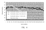
- FIG. 4 schematically illustrates the capacity of the coin-type cells produced from the powders of Example 1 and Example 2 at a charge rate of 1C and a discharge rate of 3C.
- FIG. 5 schematically illustrates the life cycle retention of the coin-type cells produced from the powders of Example 1 and Example 2 at a charge rate of 1C and a discharge rate of 3C.
- the initial capacity of the cathode material with the single carbon coating is higher than the cathode material with the double carbon coatings.
- the capacity of the cathode material with the single carbon coating abruptly reduces.
- the capacity of the cathode material with the double carbon coatings is substantially equal to the initial capacity.
- the cathode material with the double carbon coatings still has 100% of life cycle retention. Consequently, the cell produced from the cathode material with the double carbon coatings has obviously longer cycle life.
- the cycle life of the cell produced from the cathode material with the double carbon coatings has been increased at least three times when compared with the cathode material with the single carbon coating.
- Iron phosphate hydrate (2 mole) was added to pure water (600 ml).
- Polyvinylpyrrolidone (PVP K30, 10 ml) was added to a dispersed solution. While stirring, a wet dispersion process (e.g. a ball mill process or an ultrasonic dispersion process) was performed to form a nanoscale particle mixture in solution. Lithium hydroxide monohydrate (2 mole) and fructose (0.07 mole) were added. After the solution was uniformly stirred, the solution was spray-dried to form a powdery precursor.
- the powdery precursor was placed in an aluminum oxide crucible. Under a protective atmosphere such as nitrogen or argon gas, the powdery precursor was sintered at high temperature up to 800°C and maintained at this temperature for at least five hours. Consequently, the carbon coating was subject to excellent carbonation. Under this circumstance, a cathode material covered with a single carbon coating (also referred as an "A product powder") was produced. The content of carbon in the A product powder was 2 ⁇ 2.5%.
- the cathode material covered with the single carbon coating (i.e. the A product powder), which was prepared in Example 3, was further subject to a second carbon coating formation process.
- a second carbon coating formation process Firstly, several coal tar pitch solutions (0.6 ⁇ 1%) were prepared. These coal tar pitch solutions were obtained by dissolving different amount of coal tar pitch (0.6g, 0.8g and 1g) into different amount of xylene (99.4 g, 99.2 g and 99 g). After the coal tar pitch was completely dissolved, 20g of the A product powder was added and uniformly mixed.
- the subsequent procedures are identical to those of Example 2, and are not redundantly described herein.
- Example 2 The physical data of the powders obtained in Example 3 and Example 4 are shown in Table 2 as follows. As shown in Table 2, the double carbon coatings may reduce the specific surface area. Moreover, the ratio of the carbon percentage of the first carbon coating to the carbon percentage of the second carbon coating is in the range between 4:3 and 1:1. Table 2: (mAh/g) Single carbon coating Double carbon coatings 0.6% coal tar pitch 0.8% coal tar pitch 1% coal tar pitch C% 2.283% 4.028% (1.745%)* 4.465% (2.182%)* 4.565% (2.282%)* S.A. 18.9 14.66 14.04 12.83 * the value in the parenthesis indicates the carbon percentage of the second carbon coating
- FIG. 6 schematically illustrates the capacity of the coin-type cells produced from the powders of Example 3 and Example 4 at a charge rate of 1C and a discharge rate of 3C.
- FIG. 7 schematically illustrates the life cycle retention of the coin-type cells produced from the powders of Example 3 and Example 4 at a charge rate of 1C and a discharge rate of 3C.
- the initial capacity of the cathode material with the single carbon coating is higher than the cathode material with the double carbon coatings.
- the capacity of the cathode material with the single carbon coating abruptly reduces.
- the capacity of the cathode material with the double carbon coatings is substantially equal to the initial capacity.
- the cathode material with the double carbon coatings still has 100% of life cycle retention. Consequently, the cell produced from the cathode material with the double carbon coatings has obviously longer cycle life.
- the cycle life of the cell produced from the cathode material with the double carbon coatings has been increased at least 1.5 times when compared with the cycle life of the cathode material with the single carbon coating.
- the cathode material covered with the single carbon coating (i.e. the M product powder), which was prepared in Example 1, was further subjected to a second carbon coating formation process.
- the subsequent sintering conditions of this example were different from those of Example 2.
- the sintering procedure was performed by maintaining at 550°C for 4 hours and then maintaining at 750°C for 4 hours.
- the sintering procedure was performed by maintaining at 260°C for 2 hours and then maintaining at 900°C for 2 hours.
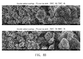
- FIGS. 8A and 8B schematically illustrate the SEM photographs of the powders obtained in Example 2 and Example 3 in different sintering conditions.
- the powder obtained by the higher-temperature thermal treatment of Example 5 has more carbon crumbs and raw edges. Consequently, the contact area between the cathode material and the electrolyte increases, and the capacity is enhanced.
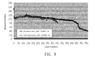
- FIG. 9 schematically illustrates the capacity of the coin-type cells produced from the powder of Example 5 at a charge rate of 1C and a discharge rate of 3C.
- the powder produced by the sintering procedure of Example 5 i.e. maintaining at 260°C for 2 hours and then maintaining at 900°C for 2 hours
- the cell may have a cycle life of 450 charge/discharge cycles (> 80% of life cycle retention).
- carbon source of the second carbon coating is 1% coal tar pitch
- the cell has a cycle life of up to 650 charge/discharge cycles (> 80% of life cycle retention).
- the cathode material covered with the single carbon coating (i.e. the M product powder), which was prepared in Example 1, was further subjected to a second carbon coating formation process.
- the subsequent sintering conditions of this example were different from those of Example 2.
- the sintering procedure was performed by maintaining at 550°C for 4 hours and then maintaining at 750°C for 4 hours.
- Example 6 the sintering procedure was performed by maintaining at 550°C for 4 hours and then maintaining at 650°C for 4 hours.
- FIG. 10 schematically illustrates the capacity of the coin-type cells produced from the powder of Example 6 at a charge rate of 1C and a discharge rate of 3C.
- the powder produced by the sintering procedure of Example 6 i.e. maintaining at 550°C for 4 hours and then maintaining at 650°C for 4 hours
- Example 3 The comparisons between the physical properties and electrical properties of the powders obtained in Example 1, Example 2, Example 5 and Example 6 are shown in Table 3.
- Table 3 the sintering conditions of Example 5 and Example 6 can increase the specified surface area of the powder and effectively avoid reduction of the capacity when compared with the sintering condition of Example 2 (i.e. maintaining at 550°C for 4 hours and then maintaining at 750°C for 4 hours).
- the obtained capacity (0.1C:147 ⁇ 153/2C:106 ⁇ 114) is close to the M product powder with the single carbon coating (0.1C:155/2C:114).
- Table 3 C% S.A.
- FIG. 11 schematically illustrates the X-ray absorption spectra of the powders obtained at various sintering conditions in Example 1, Example 2, Example 6 and Example 5.
- the XRD result as shown in FIG 11 demonstrates that the peak values of the cathode material at different sintering conditions have no obvious noise. Consequently, after the second carbon coating formation process and the thermal treatment, the original olivine crystalline structure of the lithium iron phosphate-based compound is not changed. That is, the stability of the crystalline phase is not influenced.
- Example 7 a scale-up test was performed.
- 20g of the M product powder was mixed with 0.4g coal tar pitch/100g (0.4 %) and 1g coal tar pitch/100g (1 %).
- 50g of the M product powder was mixed with 1g coal tar pitch/100g and 2.5g coal tar pitch/100g. Consequently, the carbon content of Example 7 was controlled to be equal to the carbon content of Example 2.
- the sintering procedure was performed by maintaining at 550°C for 4 hours and then maintaining at 650°C for 4 hours.
- Example 7 The subsequent procedures are identical to those of Example 2, and are not redundantly described herein.
- the physical data of the powders obtained in Example 7 are shown in Table 4 as follows. As shown in Table 4, in the powder obtained by mixing 50g of the M product powder with 1g coal tar pitch/100g, the ratio of the carbon percentage of the first carbon coating to the carbon percentage of the second carbon coating is about 1:1. Moreover, in the powder obtained by mixing 50g of the M product powder with 2.5g coal tar pitch/100g, the ratio of the carbon percentage of the first carbon coating to the carbon percentage of the second carbon coating is close to 1:2.
- FIG. 12 schematically illustrates the capacity of the coin-type cells produced from the powder of Example 7 at a charge rate of 1C and a discharge rate of 3C.
- the powder produced by the sintering procedure of Example 6 i.e. maintaining at 550°C for 4 hours and then maintaining at 650°C for 4 hours
- the scale-up test may allow the cell to have a cycle life of up to 500 charge/discharge cycles at 100% of life cycle retention.
- this production process has the potential of mass production and reduced fabricating cost.
- the cell produced from the cathode material with the double carbon coatings has obviously longer cycle life.
- the cell produced from the cathode material with the double carbon coatings has a cycle life of up to 500 charge/discharge cycles at 100% of life cycle retention.
- the conventional coin-type cell has a life cycle of about 100-200 cycles.
- the cycle life of the cell produced from the cathode material with the double carbon coatings has been increased at least two times.
- the adjustment of the sintering temperature can restore the capacity to be close to the capacity of the cathode material with the single carbon coating.
- the electrical properties and the physical properties of the cathode material with the double carbon coatings are related to the carbon content of the second carbon coating.
- the satisfactory cycle life is achieved when the ratio of the carbon percentage of the first carbon coating to the carbon percentage of the second carbon coating is close to 1:1 or 1:2.
- the present invention provides a cathode material with double carbon coatings.
- the cathode material comprises a lithium metal phosphate matrix and two carbon coatings coated on the lithium metal phosphate matrix.
- the carbon source of the first carbon coating is a carbohydrate or a water-soluble macromolecule compound having relatively smaller molecular weight. Consequently, the first carbon coating has a looser structure, and a space is retained in the first carbon coating for allowing expansion and contraction of the structure during the charging and discharging process. Under this circumstance, the possibility of peeling off the carbon structure will be minimized.
- the carbon source of the second carbon coating is a macromolecule compound having relatively higher molecular weight.
- the carbon source of the second carbon coating is an aromatic compound such as coal tar pitch or petroleum pitch.
- the second carbon coating has a denser structure in order to reduce the structural damage of the lithium metal phosphate matrix by the acidic substance of the electrolyte.
Landscapes
- Chemical & Material Sciences (AREA)
- Chemical Kinetics & Catalysis (AREA)
- Electrochemistry (AREA)
- General Chemical & Material Sciences (AREA)
- Crystallography & Structural Chemistry (AREA)
- Inorganic Chemistry (AREA)
- Engineering & Computer Science (AREA)
- Manufacturing & Machinery (AREA)
- Battery Electrode And Active Subsutance (AREA)
Abstract
Description
- The present invention relates to a cathode material, and more particularly to a cathode material with double carbon coatings.
- With the diversified development of electronic products, the demands on portable energy sources are gradually increased. For example, consumer electronic devices, medical instruments, electric bicycles, electric vehicles or electric hand tools use portable power sources as sources of electric power. Among these portable power sources, rechargeable batteries (also referred as secondary cells) are widely used because the electrochemical reactions thereof are electrically reversible. Moreover, among the conventional secondary cells, lithium-ion secondary cells have high volumetric capacitance, low pollution, good charge and discharge cycle characteristics, and no memory effect. Consequently, the lithium-ion secondary cells are more potential for development.
- As known, the performance of the secondary cell is influenced by many factors. Generally, the material for producing a positive electrode (also referred as a cathode) is more critical to the performance of the secondary cell. Because of good electrochemical characteristics, low environmental pollution, better security, abundant raw material sources, high specific capacity, good cycle performance, good thermal stability and high charge/discharge efficiency, the lithium iron phosphate-based compound having an olivine structure or a NASICON structure is considered to be the potential lithium-ion battery cathode material.
- On the other hand, with increasing environmental awareness, electric vehicle technologies have received considerable attention in recent years. Generally, electric vehicles use rechargeable batteries (i.e. secondary cells) as the power sources. The economic benefits of the secondary cells not only depend on the electrical properties but also depend on the cycle life.
- Therefore, there is a need of providing a cathode material of a secondary cell with enhanced cycle life.
- The present invention provides a cathode material with double carbon coatings. By combining two types of carbon layers together to increase the adhesion of carbon on the lithium metal phosphate matrix, the problem of causing reduction of the material performance during the charging and discharging process will be avoided. Due to the double carbon coatings, the overall structural strength of the cathode material is enhanced, the influence on the structural flexibility during the charging and discharging process is reduced, and the structural damage caused by the acidic substance of the electrolyte is reduced. As a consequence, the use life of the cathode material is prolonged.
- In accordance with an aspect of the present invention, there is provided a cathode material with double carbon coatings. The cathode material includes a lithium metal phosphate matrix, a first carbon coating, and a second carbon coating. The first carbon coating is coated on the lithium metal phosphate matrix. The second carbon coating is coated on the first carbon coating. A carbon source of the first carbon coating is a carbohydrate or a water-soluble macromolecule compound having relatively smaller molecular weight. A carbon source of the second carbon coating is a macromolecule compound having relatively higher molecular weight.
- In accordance with another aspect of the present invention, there is provided a process of manufacturing a cathode material with double carbon coatings. Firstly, a lithium metal phosphate matrix and a carbon source of a first carbon coating are provided, and the mixture of the lithium metal phosphate matrix and the carbon source of the first carbon coating are thermally treated by sintering. Consequently, a cathode material with a single carbon coating is obtained. Meanwhile, the first carbon coating is coated on the lithium metal phosphate matrix. Then, a carbon source of a second carbon coating is added to the cathode material with the single carbon coating, and the mixture of the carbon source of the second carbon coating and the cathode material with the single carbon coating are thermally treated by sintering. Consequently, the cathode material with the double carbon coatings is obtained. The carbon source of the first carbon coating is a carbohydrate or a water-soluble macromolecule compound having relatively smaller molecular weight. The carbon source of the second carbon coating is a macromolecule compound having relatively higher molecular weight.
- The above contents of the present invention will become more readily apparent to those ordinarily skilled in the art after reviewing the following detailed description and accompanying drawings, in which:
-
-
FIG. 1 is a schematic view illustrating a cathode material with double carbon coatings according to an embodiment of the present invention; -
FIG. 2 schematically illustrates the X-ray absorption spectra of the powders obtained in Example 1 and Example 2; -
FIG. 3 schematically illustrates the SEM photographs of the powders obtained in Example 1 and Example 2; -
FIG. 4 schematically illustrates the capacity of the coin-type cells produced from the powders of Example 1 and Example 2 at a charge rate of 1C and a discharge rate of 3C; -
FIG. 5 schematically illustrates the life cycle retention of the coin-type cells produced from the powders of Example 1 and Example 2 at a charge rate of 1C and a discharge rate of 3C; -
FIG. 6 schematically illustrates the capacity of the coin-type cells produced from the powders of Example 3 and Example 4 at a charge rate of 1C and a discharge rate of 3C; -
FIG. 7 schematically illustrates the life cycle retention of the coin-type cells produced from the powders of Example 3 and Example 4 at a charge rate of 1C and a discharge rate of 3C; -
FIGS. 8A and8B schematically illustrate the SEM photographs of the powders obtained in Example 2 and Example 3 in different sintering conditions; -
FIG. 9 schematically illustrates the capacity of the coin-type cells produced from the powder of Example 5 at a charge rate of 1C and a discharge rate of 3C; -
FIG. 10 schematically illustrates the capacity of the coin-type cells produced from the powder of Example 6 at a charge rate of 1C and a discharge rate of 3C; -
FIG. 11 schematically illustrates the X-ray absorption spectra of the powders obtained in Example 2, Example 5 and Example 6; and -
FIG. 12 schematically illustrates the capacity of the coin-type cells produced from the powder of Example 7 at a charge rate of 1C and a discharge rate of 3C. - The present invention will now be described more specifically with reference to the following embodiments. It is to be noted that the following descriptions of preferred embodiments of this invention are presented herein for purpose of illustration and description only. It is not intended to be exhaustive or to be limited to the precise form disclosed.
- The present invention provides a cathode material with double carbon coatings. The cathode material comprises a lithium metal phosphate matrix and two carbon coatings coated on the lithium metal phosphate matrix. Due to the double carbon coatings, the overall structural strength of the cathode material is enhanced, the influence on the structural flexibility during the charging and discharging process is reduced, and the structural damage caused by the acidic substance of the electrolyte is reduced. As a consequence, the use life of the cathode material is prolonged.
- In accordance with the present invention, the cathode material with double carbon coatings is produced by firstly providing a cathode material with a single carbon coating and then another carbon coating is coated thereon.
FIG. 1 is a schematic view illustrating a cathode material with double carbon coatings according to an embodiment of the present invention. As shown inFIG. 1 , thecathode material 10 of the present invention mainly comprises a lithiummetal phosphate matrix 11, afirst carbon coating 12, and asecond carbon coating 13. Thefirst carbon coating 12 is coated on the lithiummetal phosphate matrix 11. The metal element of the lithiummetal phosphate matrix 11 is for example iron, cobalt, nickel, manganese or copper, but is not limited thereto. In this embodiment, the lithiummetal phosphate matrix 11 is illustrated by referring to a lithium iron phosphate (LiFePO4) material. The example of the lithiummetal phosphate matrix 11 is not limited to lithium iron phosphate. - The raw materials for synthesizing the lithium iron phosphate material comprise iron powder or iron-containing compound, phosphoric acid or phosphate compound, and lithium carbonate or lithium hydroxide. After the above materials and the carbon source of the first carbon coating are subject to a dry processing reaction or a wet processing reaction, the mixture is spray-dried and granulated to form a carbon-containing lithium iron phosphate precursor. Under a protective atmosphere such as nitrogen or argon gas, the precursor is thermally treated by sintering. Consequently, a cathode material with a single carbon coating is produced. The carbon source of the first carbon coating is a carbohydrate or a water-soluble macromolecule compound having relatively smaller molecular weight. For example, the carbohydrate having relatively smaller molecular weight is a monosaccharide, a disaccharide or a polysaccharide. An example of the water-soluble macromolecule compound includes but is not limited to polyvinyl alcohol (PVA) or polyvinylpyrrolidone (PVP).
- Then, a second carbon coating formation process is performed. The carbon source of the second carbon coating is a macromolecule compound having relatively higher molecular weight. Preferably, the carbon source of the second carbon coating is an aromatic compound such as coal tar pitch or petroleum pitch. The carbon source of the second carbon coating is dissolved in an organic solvent. Then, the cathode material with a single carbon coating is added and uniformly mixed. Under a protective atmosphere such as nitrogen or argon gas, the mixture is thermally treated by sintering. Consequently, a cathode material with double carbon coatings is produced.
- The preparation process and efficacy of the cathode material with double carbon coatings will be illustrated in the following examples.
- Phosphoric acid (85%, 2 moles) was dissolved in deionized water (600 ml) to form an acidic solution. Then, iron powder (≧99%, 2 moles) was added to the acidic solution. After reaction, a product containing iron and phosphorous is formed. This solution was continuously stirred for 24 hours to provide complete dispersion. Triton X-100 (10 ml), a non-ionic surfactant, was then added to the dispersed solution. Lithium hydroxide monohydrate (1 mole) was added to the resulting solution while it was thoroughly stirred. Lithium carbonate (1 mole) was then added. Consequently, a precursor containing iron, phosphorous and lithium at a molar ratio of 1:1:1 was produced. The precursor was analyzed and identified by inductively coupled plasma atomic emission spectrometry (ICP/AES).
- Then, vanadium pentoxide (0.04 mole, V2O5) and fructose (0.07 mole) were added to the resulting precursor. A wet dispersion process was performed to form a semicrystalline nanoscale particle mixture in solution. The mixture was spray-dried to form a powdery precursor. Then, the powdery precursor was placed in an aluminum oxide crucible. Under a protective atmosphere such as nitrogen or argon gas, the powdery precursor was sintered at high temperature up to 800°C and maintained at this temperature for at least five hours. Under this circumstance, a cathode material covered with a single carbon coating (also referred as an "M product powder") was produced. The content of carbon in the M product powder was 1~1.5%.
- The cathode material covered with the single carbon coating (i.e. the M product powder), which was prepared in Example 1, was further subject to a second carbon coating formation process. Firstly, several coal tar pitch solutions (0.4~1%) were prepared. These coal tar pitch solutions were obtained by dissolving different amounts of coal tar pitch (0.4g, 0.6g, 0.8g and 1g) into different amounts of xylene (99.6g, 99.4 g, 99.2 g and 99 g). After the coal tar pitch was completely dissolved, 20g of the M product powder was added and uniformly mixed. The obtained mixture solution was subject to a suction vacuum treatment in order to remove air from pores of the powder. The mixture solution was then stirred by a homogenizer and mixed by a ball mill jar. Consequently, the coal tar pitch was coated on the surface of the M product powder more uniformly. The mixture was heated to 150°C to remove xylene. Consequently, a uniform mixture, i.e. coal tar pitch coated on the M product powder, was produced. Then, the mixture was sintered in a furnace under a nitrogen or argon atmosphere. The furnace was raised to 550°C at a ramp rate of 5°C/min and maintained at 550°C for 4 hours, then raised to 750°C and maintained at 750°C for 4 hours, and finally reduced to room temperature. Consequently, a cathode material with double carbon coatings was produced.
- The powders obtained in Example 1 and Example 2 were analyzed by an X-ray diffractometer (XRD) and observed by a scanning electron microscope (SEM). The XRD result and the SEM photograph are shown in
FIG. 2 andFIG. 3 , respectively. InFIG. 2 , the upper curve indicates the XRD result of a cathode material with double carbon coatings (for example coated with 0.6% coal tar pitch and obtained in Example 2), and the lower curve indicates the XRD result of a cathode material with a single carbon coating (for example obtained in Example 1). The XRD result demonstrates that the peak values of the cathode material with the double carbon coatings have no obvious noise when compared with the cathode material with the single carbon coating. Consequently, after the second carbon coating formation process and the thermal treatment, the original olivine crystalline structure of the lithium iron phosphate-based compound is not changed. That is, the stability of the crystalline phase is not influenced. InFIG. 3 , two SEM photographs of the cathode material with the single carbon coating are shown in the left side of the drawing, and two SEM photographs of the cathode material with the double carbon coatings are shown in the right side of the drawing. It is found that the cathode material with the double carbon coatings has the thicker carbon coating. Moreover, since two carbon coating formation processes have been performed, the cathode material with the double coatings has a smoother surface and less small-sized particles. Moreover, since the pores between particles of the cathode material with the double coatings are reduced, the particles are subject to aggregation. - The powders obtained in Example 1 and Example 2 were coated on aluminum substrates in order to form a cathode element and assemble coin-type cells. The electric properties of the coin-type cells were tested. The test results are listed in Table 1. As shown in Table 1, the capacity of the cathode material with the double carbon coatings is slightly reduced. It is inferred that the thicker carbon coatings may hinder passage of ions. On the other hand, the double carbon coatings may smooth the surfaces of the particles and reduce the specific surface area (S.A.). Moreover, the ratio of the carbon percentage of the first carbon coating to the carbon percentage of the second carbon coating is in the range between 1:1 and 1:2.
Table 1: (mAh/g) Single carbon coating Double carbon coatings 0.4% coal tar pitch 0.6% coal tar pitch 1% coal tar pitch 0.1C C/ D 151 141 156 151 155 126 137 128 153 129 142 133 153 130 142 136 1C C/2C D 130 143 138 83 95 88 83 95 90 83 95 87 C% 1.18% 2.539%
(1.179%)*2.734%
(1.554%)*3.290%
(2.11%)*S.A. 10.9 6.72 6.23 6.3 * the value in the parenthesis indicates the carbon percentage of the second carbon coating -
FIG. 4 schematically illustrates the capacity of the coin-type cells produced from the powders of Example 1 and Example 2 at a charge rate of 1C and a discharge rate of 3C.FIG. 5 schematically illustrates the life cycle retention of the coin-type cells produced from the powders of Example 1 and Example 2 at a charge rate of 1C and a discharge rate of 3C. As shown inFIG. 4 , the initial capacity of the cathode material with the single carbon coating is higher than the cathode material with the double carbon coatings. However, after about the 150-th charge/discharge cycle, the capacity of the cathode material with the single carbon coating abruptly reduces. On the other hand, after about the 500-th charge/discharge cycle, the capacity of the cathode material with the double carbon coatings is substantially equal to the initial capacity. Similarly, as shown inFIG. 5 , after about the 500-th charge/discharge cycle, the cathode material with the double carbon coatings still has 100% of life cycle retention. Consequently, the cell produced from the cathode material with the double carbon coatings has obviously longer cycle life. Moreover, in case that the 80% of life cycle retention reaches, the cycle life of the cell produced from the cathode material with the double carbon coatings has been increased at least three times when compared with the cathode material with the single carbon coating. - Iron phosphate hydrate (2 mole) was added to pure water (600 ml). Polyvinylpyrrolidone (PVP K30, 10 ml) was added to a dispersed solution. While stirring, a wet dispersion process (e.g. a ball mill process or an ultrasonic dispersion process) was performed to form a nanoscale particle mixture in solution. Lithium hydroxide monohydrate (2 mole) and fructose (0.07 mole) were added. After the solution was uniformly stirred, the solution was spray-dried to form a powdery precursor.
- Then, the powdery precursor was placed in an aluminum oxide crucible. Under a protective atmosphere such as nitrogen or argon gas, the powdery precursor was sintered at high temperature up to 800°C and maintained at this temperature for at least five hours. Consequently, the carbon coating was subject to excellent carbonation. Under this circumstance, a cathode material covered with a single carbon coating (also referred as an "A product powder") was produced. The content of carbon in the A product powder was 2~2.5%.
- The cathode material covered with the single carbon coating (i.e. the A product powder), which was prepared in Example 3, was further subject to a second carbon coating formation process. Firstly, several coal tar pitch solutions (0.6~1%) were prepared. These coal tar pitch solutions were obtained by dissolving different amount of coal tar pitch (0.6g, 0.8g and 1g) into different amount of xylene (99.4 g, 99.2 g and 99 g). After the coal tar pitch was completely dissolved, 20g of the A product powder was added and uniformly mixed. The subsequent procedures are identical to those of Example 2, and are not redundantly described herein.
- The physical data of the powders obtained in Example 3 and Example 4 are shown in Table 2 as follows. As shown in Table 2, the double carbon coatings may reduce the specific surface area. Moreover, the ratio of the carbon percentage of the first carbon coating to the carbon percentage of the second carbon coating is in the range between 4:3 and 1:1.
Table 2: (mAh/g) Single carbon coating Double carbon coatings 0.6% coal tar pitch 0.8% coal tar pitch 1% coal tar pitch C% 2.283% 4.028%
(1.745%)*4.465%
(2.182%)*4.565%
(2.282%)*S.A. 18.9 14.66 14.04 12.83 * the value in the parenthesis indicates the carbon percentage of the second carbon coating -
FIG. 6 schematically illustrates the capacity of the coin-type cells produced from the powders of Example 3 and Example 4 at a charge rate of 1C and a discharge rate of 3C.FIG. 7 schematically illustrates the life cycle retention of the coin-type cells produced from the powders of Example 3 and Example 4 at a charge rate of 1C and a discharge rate of 3C. As shown inFIG. 6 , the initial capacity of the cathode material with the single carbon coating is higher than the cathode material with the double carbon coatings. However, after about the 300-th charge/discharge cycle, the capacity of the cathode material with the single carbon coating abruptly reduces. On the other hand, after about the 450-th charge/discharge cycle, the capacity of the cathode material with the double carbon coatings is substantially equal to the initial capacity. Similarly, as shown inFIG. 7 , after about the 500-th charge/discharge cycle, the cathode material with the double carbon coatings still has 100% of life cycle retention. Consequently, the cell produced from the cathode material with the double carbon coatings has obviously longer cycle life. Moreover, in case that the 80% of life cycle retention reaches, the cycle life of the cell produced from the cathode material with the double carbon coatings has been increased at least 1.5 times when compared with the cycle life of the cathode material with the single carbon coating. - The cathode material covered with the single carbon coating (i.e. the M product powder), which was prepared in Example 1, was further subjected to a second carbon coating formation process. The subsequent sintering conditions of this example were different from those of Example 2. In Example 2, the sintering procedure was performed by maintaining at 550°C for 4 hours and then maintaining at 750°C for 4 hours. In Example 5, the sintering procedure was performed by maintaining at 260°C for 2 hours and then maintaining at 900°C for 2 hours.
-
FIGS. 8A and8B schematically illustrate the SEM photographs of the powders obtained in Example 2 and Example 3 in different sintering conditions. As shown inFIGS. 8A and8B , the powder obtained by the higher-temperature thermal treatment of Example 5 has more carbon crumbs and raw edges. Consequently, the contact area between the cathode material and the electrolyte increases, and the capacity is enhanced. -
FIG. 9 schematically illustrates the capacity of the coin-type cells produced from the powder of Example 5 at a charge rate of 1C and a discharge rate of 3C. In case that the capacity as shown inFIG. 9 is converted into the life cycle retention, the powder produced by the sintering procedure of Example 5 (i.e. maintaining at 260°C for 2 hours and then maintaining at 900°C for 2 hours) may allow the cell to have a cycle life of 450 charge/discharge cycles (> 80% of life cycle retention). Moreover, in case that carbon source of the second carbon coating is 1% coal tar pitch, the cell has a cycle life of up to 650 charge/discharge cycles (> 80% of life cycle retention). - The cathode material covered with the single carbon coating (i.e. the M product powder), which was prepared in Example 1, was further subjected to a second carbon coating formation process. The subsequent sintering conditions of this example were different from those of Example 2. In Example 2, the sintering procedure was performed by maintaining at 550°C for 4 hours and then maintaining at 750°C for 4 hours. In Example 6, the sintering procedure was performed by maintaining at 550°C for 4 hours and then maintaining at 650°C for 4 hours.
-
FIG. 10 schematically illustrates the capacity of the coin-type cells produced from the powder of Example 6 at a charge rate of 1C and a discharge rate of 3C. In case that the capacity as shown inFIG. 10 is converted into the life cycle retention, the powder produced by the sintering procedure of Example 6 (i.e. maintaining at 550°C for 4 hours and then maintaining at 650°C for 4 hours) may allow the cell to have a cycle life of up to 500 charge/discharge cycles at 100% of life cycle retention. - The comparisons between the physical properties and electrical properties of the powders obtained in Example 1, Example 2, Example 5 and Example 6 are shown in Table 3. As shown in Table 3, the sintering conditions of Example 5 and Example 6 can increase the specified surface area of the powder and effectively avoid reduction of the capacity when compared with the sintering condition of Example 2 (i.e. maintaining at 550°C for 4 hours and then maintaining at 750°C for 4 hours). The obtained capacity (0.1C:147~153/2C:106~114) is close to the M product powder with the single carbon coating (0.1C:155/2C:114).
Table 3: C% S.A. 0.1CD 0.1CD 2CD 2CD 3CD 3CD Maximum capacity Single carbon coating 1.18% 10.9 155 153 113 114 108 109 118 Double carbon coating_ 0.4% coal tar pitch 2.539% 6.72 131 135 94 94 94 85 86 550°C 4h/ 750°C 4h (1.179%)* Double carbon coating_ 1 % coal tar pitch 3.29% 6.3 136 140 92 92 81 82 103 550°C 4h/ 750°C 4h (2.11%)* Double carbon coating_ 0.4% coal tar pitch 1.797% 7.56 153 151 113 111 101 102 113 260°C 2h/900°C 2h (0.617)* Double carbon coating_ 1 % coal tar pitch 2.963% 6.96 149 147 108 110 100 101 123 260°C 2h/900°C 2h (1.783%)* Double carbon coating_ 0.4% coal tar pitch 2.33% 7.06 151 152 113 114 104 105 120 550°C 4h/ 650°C 4h (1.15%)* Double carbon coating_ 1 % coal tar pitch 3.260% 8.1 147 149 106 107 96 98 115 550°C 4h/ 650°C 4h (2.08%)* * the value in the parenthesis indicates the carbon percentage of the second carbon coating -
FIG. 11 schematically illustrates the X-ray absorption spectra of the powders obtained at various sintering conditions in Example 1, Example 2, Example 6 and Example 5. The XRD result as shown inFIG 11 demonstrates that the peak values of the cathode material at different sintering conditions have no obvious noise. Consequently, after the second carbon coating formation process and the thermal treatment, the original olivine crystalline structure of the lithium iron phosphate-based compound is not changed. That is, the stability of the crystalline phase is not influenced. - In this example, a scale-up test was performed. The cathode material covered with the single carbon coating (i.e. the M product powder), which was prepared in Example 1, was further subjected to a second carbon coating formation process. In Example 2, 20g of the M product powder was mixed with 0.4g coal tar pitch/100g (0.4 %) and 1g coal tar pitch/100g (1 %). In this example (Example 7), 50g of the M product powder was mixed with 1g coal tar pitch/100g and 2.5g coal tar pitch/100g. Consequently, the carbon content of Example 7 was controlled to be equal to the carbon content of Example 2. Moreover, in Example 7, the sintering procedure was performed by maintaining at 550°C for 4 hours and then maintaining at 650°C for 4 hours. The subsequent procedures are identical to those of Example 2, and are not redundantly described herein. The physical data of the powders obtained in Example 7 are shown in Table 4 as follows. As shown in Table 4, in the powder obtained by mixing 50g of the M product powder with 1g coal tar pitch/100g, the ratio of the carbon percentage of the first carbon coating to the carbon percentage of the second carbon coating is about 1:1. Moreover, in the powder obtained by mixing 50g of the M product powder with 2.5g coal tar pitch/100g, the ratio of the carbon percentage of the first carbon coating to the carbon percentage of the second carbon coating is close to 1:2.
Table 4: (mAh/g) Single carbon coating Double carbon coatings 50g lithium iron phosphate_ 1g coal tar pitch / 100g 50g lithium iron phosphate_ 2.5g coal tar pitch /100g C% 1.18% 2.35%
(1.17%)*3.42%
(2.24%)*S.A. 10.9 8.4 8.88 * the value in the parenthesis indicates the carbon percentage of the second carbon coating -
FIG. 12 schematically illustrates the capacity of the coin-type cells produced from the powder of Example 7 at a charge rate of 1C and a discharge rate of 3C. In case that the capacity as shown inFIG. 12 is converted into the life cycle retention, the powder produced by the sintering procedure of Example 6 (i.e. maintaining at 550°C for 4 hours and then maintaining at 650°C for 4 hours) subject to the scale-up test may allow the cell to have a cycle life of up to 500 charge/discharge cycles at 100% of life cycle retention. In other words, this production process has the potential of mass production and reduced fabricating cost. - From the above embodiments, it is found that the cell produced from the cathode material with the double carbon coatings has obviously longer cycle life. For example, the cell produced from the cathode material with the double carbon coatings has a cycle life of up to 500 charge/discharge cycles at 100% of life cycle retention. As known, the conventional coin-type cell has a life cycle of about 100-200 cycles. In comparison with the conventional coin-type cell, the cycle life of the cell produced from the cathode material with the double carbon coatings has been increased at least two times. Although the capacity of the cathode material with the double carbon coatings is slightly reduced, the adjustment of the sintering temperature can restore the capacity to be close to the capacity of the cathode material with the single carbon coating. Moreover, the electrical properties and the physical properties of the cathode material with the double carbon coatings are related to the carbon content of the second carbon coating. In accordance with the optimal conditions, the satisfactory cycle life is achieved when the ratio of the carbon percentage of the first carbon coating to the carbon percentage of the second carbon coating is close to 1:1 or 1:2.
- From the above descriptions, the present invention provides a cathode material with double carbon coatings. The cathode material comprises a lithium metal phosphate matrix and two carbon coatings coated on the lithium metal phosphate matrix. The carbon source of the first carbon coating is a carbohydrate or a water-soluble macromolecule compound having relatively smaller molecular weight. Consequently, the first carbon coating has a looser structure, and a space is retained in the first carbon coating for allowing expansion and contraction of the structure during the charging and discharging process. Under this circumstance, the possibility of peeling off the carbon structure will be minimized. The carbon source of the second carbon coating is a macromolecule compound having relatively higher molecular weight. Preferably, the carbon source of the second carbon coating is an aromatic compound such as coal tar pitch or petroleum pitch. Consequently, the second carbon coating has a denser structure in order to reduce the structural damage of the lithium metal phosphate matrix by the acidic substance of the electrolyte. By combining two types of carbon layers together to increase the adhesion of carbon on the lithium metal phosphate matrix, the problem of causing reduction of the material performance during the charging and discharging process will be avoided. Due to the double carbon coatings, the overall structural strength of the cathode material is enhanced, the influence on the structural flexibility during the charging and discharging process is reduced, and the structural damage caused by the acidic substance of the electrolyte is reduced. As a consequence, the use life of the cathode material is prolonged.
- While the invention has been described in terms of what is presently considered to be the most practical and preferred embodiments, it is to be understood that the invention needs not be limited to the disclosed embodiment. On the contrary, it is intended to cover various modifications and similar arrangements included within the spirit and scope of the appended claims which are to be accorded with the broadest interpretation so as to encompass all such modifications and similar structures.
Claims (19)
- A cathode material with double carbon coatings, the cathode material comprising:a lithium metal phosphate matrix;a first carbon coating coated on the lithium metal phosphate matrix; anda second carbon coating coated on the first carbon coating,wherein a carbon source of the first carbon coating is a carbohydrate or a water-soluble macromolecule compound having relatively smaller molecular weight, and a carbon source of the second carbon coating is a macromolecule compound having relatively higher molecular weight.
- The cathode material according to claim 1, wherein the metal of the lithium metal phosphate matrix is iron, cobalt, nickel, manganese or copper.
- The cathode material according to claim 1, wherein the carbohydrate having relatively smaller molecular weight is a monosaccharide, a disaccharide or a polysaccharide.
- The cathode material according to claim 1, wherein the water-soluble macromolecule compound having relatively smaller molecular weight includes polyvinyl alcohol or polyvinylpyrrolidone.
- The cathode material according to claim 1, wherein the macromolecule compound having relatively higher molecular weight is an aromatic compound.
- The cathode material according to claim 1, wherein the macromolecule compound having relatively higher molecular weight is coal tar pitch or petroleum pitch.
- The cathode material according to claim 1, wherein in the cathode material, ratio of a carbon percentage of the first carbon coating to a carbon percentage of the second carbon coating is in the range between 4:3 and 1:2.
- A process of manufacturing a cathode material with double carbon coatings, the process comprising steps of:providing a lithium metal phosphate matrix and a carbon source of a first carbon coating, and thermally treating the mixture of the lithium metal phosphate matrix and the carbon source of the first carbon coating by sintering, so that a cathode material with a single carbon coating is obtained, wherein the first carbon coating is coated on the lithium metal phosphate matrix;adding a carbon source of a second carbon coating to the cathode material with the single carbon coating, and thermally treating the mixture of the carbon source of the second carbon coating and the cathode material with the single carbon coating by sintering, so that the cathode material with the double carbon coatings is obtained,wherein the carbon source of the first carbon coating is a carbohydrate or a water-soluble macromolecule compound having relatively smaller molecular weight, and the carbon source of the second carbon coating is a macromolecule compound having relatively higher molecular weight.
- The process according to claim 8, wherein the metal of the lithium metal phosphate matrix is iron, cobalt, nickel, manganese or copper.
- The process according to claim 8, wherein the carbohydrate having relatively smaller molecular weight is a monosaccharide, a disaccharide or a polysaccharide.
- The process according to claim 8, wherein the water-soluble macromolecule compound having relatively smaller molecular weight includes polyvinyl alcohol or polyvinylpyrrolidone.
- The process according to claim 8, wherein the macromolecule compound having relatively higher molecular weight is an aromatic compound.
- The process according to claim 8, wherein the macromolecule compound having relatively higher molecular weight is coal tar pitch or petroleum pitch.
- The process according to claim 8, wherein in the cathode material, ratio of a carbon percentage of the first carbon coating to a carbon percentage of the second carbon coating is in the range between 4:3 and 1:2.
- The process according to claim 8, wherein the carbon source of the second carbon coating is dissolved in an organic solvent.
- The process according to claim 15, wherein the organic solvent is xylene.
- The process according to claim 8, wherein the mixture of the carbon source of the second carbon coating and the cathode material with the single carbon coating is thermally treated at 550°C for 4 hours and then at 750°C for 4 hours.
- The process according to claim 8, wherein the mixture of the carbon source of the second carbon coating and the cathode material with the single carbon coating is thermally treated at 260°C for 2 hours and then at 900°C for 2 hours.
- The process according to claim 8, wherein the mixture of the carbon source of the second carbon coating and the cathode material with the single carbon coating is thermally treated at 550°C for 4 hours and then at 650°C for 4 hours.
Applications Claiming Priority (2)
| Application Number | Priority Date | Filing Date | Title |
|---|---|---|---|
| US201161453298P | 2011-03-16 | 2011-03-16 | |
| PCT/CN2012/072472 WO2012122951A1 (en) | 2011-03-16 | 2012-03-16 | Cathode material having double-layer carbon coating and preparation method therefor |
Publications (3)
| Publication Number | Publication Date |
|---|---|
| EP2687482A1 true EP2687482A1 (en) | 2014-01-22 |
| EP2687482A4 EP2687482A4 (en) | 2014-08-13 |
| EP2687482B1 EP2687482B1 (en) | 2018-05-09 |
Family
ID=46830061
Family Applications (1)
| Application Number | Title | Priority Date | Filing Date |
|---|---|---|---|
| EP12757217.0A Active EP2687482B1 (en) | 2011-03-16 | 2012-03-16 | Cathode material having double-layer carbon coating and preparation method therefor |
Country Status (9)
| Country | Link |
|---|---|
| US (1) | US20140004421A1 (en) |
| EP (1) | EP2687482B1 (en) |
| JP (1) | JP2014512639A (en) |
| KR (1) | KR101595165B1 (en) |
| CN (1) | CN103347813A (en) |
| CA (1) | CA2830111C (en) |
| RU (1) | RU2013141273A (en) |
| TW (2) | TWI543428B (en) |
| WO (1) | WO2012122951A1 (en) |
Families Citing this family (11)
| Publication number | Priority date | Publication date | Assignee | Title |
|---|---|---|---|---|
| ES2688714T3 (en) * | 2013-08-21 | 2018-11-06 | HYDRO-QUéBEC | Positive electrode material for lithium secondary battery |
| CN103682336A (en) * | 2013-12-23 | 2014-03-26 | 复旦大学 | Method for improving conductivity of pure lithium iron phosphate anode material |
| KR101812268B1 (en) * | 2014-10-10 | 2017-12-26 | 주식회사 엘지화학 | Preparation method of porous electrode active material, porous electrode active material prepared by the method, porous electrode active material, electrode comprising the same and secondary battery |
| JP6388343B2 (en) * | 2015-03-27 | 2018-09-12 | 株式会社三井E&Sホールディングス | Lithium iron phosphate positive electrode material and lithium ion secondary battery |
| JP6500578B2 (en) * | 2015-04-27 | 2019-04-17 | 株式会社デンソー | Electrode active material for non-aqueous electrolyte secondary battery, method for producing the same, and non-aqueous electrolyte secondary battery |
| CN106935834A (en) * | 2017-04-21 | 2017-07-07 | 山东大学 | A kind of porous silicon negative material of compound carbon coating and preparation method thereof |
| CN107528057A (en) * | 2017-08-31 | 2017-12-29 | 北方奥钛纳米技术有限公司 | The preparation method of carbon coating lithium titanate and carbon coating lithium titanate and application |
| CN112349905B (en) * | 2019-08-06 | 2021-11-23 | 湖南杉杉新能源有限公司 | Double-coating modified lithium ion battery positive electrode material and preparation method thereof |
| TWI801064B (en) * | 2021-12-27 | 2023-05-01 | 台灣立凱電能科技股份有限公司 | Carbon-coated cathode material and preparation method thereof |
| WO2024000427A1 (en) * | 2022-06-30 | 2024-01-04 | 宁德时代新能源科技股份有限公司 | Positive electrode active material and preparation method therefor, positive electrode sheet, secondary battery, battery module, battery pack, and electric device |
| CN115528296B (en) * | 2022-09-29 | 2023-12-29 | 欣旺达动力科技股份有限公司 | a secondary battery |
Family Cites Families (12)
| Publication number | Priority date | Publication date | Assignee | Title |
|---|---|---|---|---|
| JP4187524B2 (en) * | 2002-01-31 | 2008-11-26 | 日本化学工業株式会社 | Lithium iron phosphorus composite oxide carbon composite, method for producing the same, lithium secondary battery positive electrode active material, and lithium secondary battery |
| JP4684727B2 (en) * | 2005-04-20 | 2011-05-18 | 日本コークス工業株式会社 | Positive electrode material for lithium ion secondary battery, method for producing the same, and lithium ion secondary battery |
| US20070160752A1 (en) * | 2006-01-09 | 2007-07-12 | Conocophillips Company | Process of making carbon-coated lithium metal phosphate powders |
| CN101499522B (en) * | 2008-01-28 | 2011-12-28 | 财团法人工业技术研究院 | Lithium battery positive electrode material, its manufacturing method and lithium secondary battery using the material |
| US8088305B2 (en) * | 2008-02-22 | 2012-01-03 | Byd Company Limited | Lithium iron phosphate cathode material |
| JP5291179B2 (en) * | 2008-03-28 | 2013-09-18 | ビーワイディー カンパニー リミテッド | Method for preparing lithium iron phosphate cathode material for lithium secondary battery |
| CN101320809B (en) * | 2008-07-17 | 2011-02-09 | 深圳市贝特瑞新能源材料股份有限公司 | Lithium ion battery anode material manganese lithium phosphate and preparation method thereof |
| JP5541560B2 (en) * | 2008-10-03 | 2014-07-09 | 株式会社Gsユアサ | Positive electrode material, method for producing positive electrode material, and nonaqueous electrolyte secondary battery provided with positive electrode material produced by the production method |
| JP5509918B2 (en) * | 2009-03-27 | 2014-06-04 | 住友大阪セメント株式会社 | Method for producing positive electrode active material for lithium ion battery, positive electrode active material for lithium ion battery, electrode for lithium ion battery, and lithium ion battery |
| DE102009020832A1 (en) * | 2009-05-11 | 2010-11-25 | Süd-Chemie AG | Composite material containing a mixed lithium metal oxide |
| CN103109399B (en) * | 2010-09-10 | 2015-11-25 | 海洋王照明科技股份有限公司 | A kind of containing lithium salts-graphene composite material and preparation method thereof |
| CN102306791B (en) * | 2011-08-18 | 2014-08-06 | 合肥国轩高科动力能源股份公司 | A kind of preparation method of carbon-coated non-stoichiometric ratio lithium iron phosphorus oxide material |
-
2012
- 2012-03-16 KR KR1020137027110A patent/KR101595165B1/en active Active
- 2012-03-16 JP JP2013558297A patent/JP2014512639A/en active Pending
- 2012-03-16 CN CN2012800080128A patent/CN103347813A/en active Pending
- 2012-03-16 EP EP12757217.0A patent/EP2687482B1/en active Active
- 2012-03-16 CA CA2830111A patent/CA2830111C/en active Active
- 2012-03-16 WO PCT/CN2012/072472 patent/WO2012122951A1/en not_active Ceased
- 2012-03-16 TW TW101109195A patent/TWI543428B/en active
- 2012-03-16 US US14/005,459 patent/US20140004421A1/en not_active Abandoned
- 2012-03-16 TW TW104133166A patent/TW201605104A/en unknown
- 2012-03-16 RU RU2013141273/05A patent/RU2013141273A/en not_active Application Discontinuation
Non-Patent Citations (5)
| Title |
|---|
| By Sung ET AL: "Submitted to Supporting Information Double carbon coating of LiFePO 4 as high rate electrode for rechargeable lithium batteries**", Advanced Materials, 16 November 2010 (2010-11-16), pages 4824-4845, XP055127383, Retrieved from the Internet: URL:http://onlinelibrary.wiley.com/store/10.1002/adma.200904027/asset/supinfo/adma_200904027_sm_suppl.pdf?v=1&s=31c1d1e44a290c3b3b58a5f3ea3b29d9b002365e [retrieved on 2014-07-08] * |
| CATHERINE A. PETERS ET AL: "Coal tar dissolution in water-miscible solvents: experimental evaluation", ENVIRONMENTAL SCIENCE & TECHNOLOGY, vol. 27, no. 13, 1 October 1993 (1993-10-01), pages 2831-2843, XP055127594, ISSN: 0013-936X, DOI: 10.1021/es00049a025 * |
| See also references of WO2012122951A1 * |
| SUNG WOO OH ET AL: "Double Carbon Coating of LiFePO4 as High Rate Electrode for Rechargeable Lithium Batteries", ADVANCED MATERIALS, vol. 22, no. 43, 20 July 2010 (2010-07-20) , pages 4842-4845, XP055127346, ISSN: 0935-9648, DOI: 10.1002/adma.200904027 * |
| XUELIN YANG ET AL: "Enhanced rate performance of two-phase carbon coated LiFePO4/(C+G) using natural graphite as carbon source", JOURNAL OF POWER SOURCES, vol. 204, 24 December 2011 (2011-12-24), pages 182-186, XP055127360, ISSN: 0378-7753, DOI: 10.1016/j.jpowsour.2011.12.032 * |
Also Published As
| Publication number | Publication date |
|---|---|
| CA2830111C (en) | 2016-08-30 |
| US20140004421A1 (en) | 2014-01-02 |
| CA2830111A1 (en) | 2012-09-20 |
| CN103347813A (en) | 2013-10-09 |
| RU2013141273A (en) | 2015-04-27 |
| TW201242149A (en) | 2012-10-16 |
| KR101595165B1 (en) | 2016-02-17 |
| JP2014512639A (en) | 2014-05-22 |
| WO2012122951A1 (en) | 2012-09-20 |
| EP2687482B1 (en) | 2018-05-09 |
| KR20140010143A (en) | 2014-01-23 |
| TW201605104A (en) | 2016-02-01 |
| TWI543428B (en) | 2016-07-21 |
| EP2687482A4 (en) | 2014-08-13 |
Similar Documents
| Publication | Publication Date | Title |
|---|---|---|
| EP2687482B1 (en) | Cathode material having double-layer carbon coating and preparation method therefor | |
| JP5291179B2 (en) | Method for preparing lithium iron phosphate cathode material for lithium secondary battery | |
| US9391330B2 (en) | Electrode material, method for producing the same, electrode and battery | |
| EP4266411A1 (en) | Negative electrode active material for lithium secondary battery, method for preparing same, and lithium secondary battery comprising same | |
| KR101519325B1 (en) | Lithium manganese phosphate/carbon nanocomposites as cathode active materials for secondary lithium batteries | |
| US9666870B2 (en) | Composite electrodes for lithium ion battery and method of making | |
| KR101182433B1 (en) | Negative active material, method for preparing the same, and lithium battery comprising the same | |
| KR101589294B1 (en) | Positive electrode active material for rechargable lithium battery, method for synthesis the same, and rechargable lithium battery including the same | |
| TW201335067A (en) | Electrode material, electrode board and lithium ion battery, and method of manufacturing electrode material and electrode board | |
| KR101554944B1 (en) | The preparing method of lithium iron phosphate cathode active materials, the lithium iron phosphate cathod acive materials thereby and the secondary battery using the same | |
| KR102826392B1 (en) | Negative electrode active material and fabrication method thereof | |
| KR20220065124A (en) | Anode active material including core-shell composite and method for manufacturing same | |
| KR101440003B1 (en) | The preparing method of lithium iron phosphate cathode active materials, the lithium iron phosphate cathod acive materials thereby and the secondary battery using the same | |
| KR20150007104A (en) | The preparing method of lithium iron phosphate cathode active materials, the lithium iron phosphate cathod acive materials thereby and the secondary battery using the same | |
| KR102592037B1 (en) | Negative electrode active material for secondary battery and manufacturing method thereof | |
| KR102938491B1 (en) | Lithium doped silicon-based negative electrode active material, manufacturing method thereof, post-treatment method thereof, negative electrode and secondary battery comprising the same | |
| KR101883630B1 (en) | Titanium oxide composite doped with carbon, and method for preparing the same | |
| KR101589296B1 (en) | Positive electrode active material for rechargable lithium battery, method for synthesis the same, and rechargable lithium battery including the same | |
| KR102610479B1 (en) | Anode active material for secondary batteries and manufacturing method thereof | |
| CN110635132B (en) | Divalent metal phosphate powder and lithium metal phosphate powder for lithium ion battery and preparation method thereof | |
| EP4553920A1 (en) | Positive electrode active material for lithium secondary battery and lithium secondary battery using the same | |
| KR20250141904A (en) | Positive electrode, preparation method thereof, and all-solid-state rechargeable batteries | |
| KR20250141903A (en) | Positive electrode, preparation method thereof, and all-solid-state rechargeable batteries | |
| KR20250046399A (en) | Anode active material, method of manufacturing the same and lithium secondary battery comprising the same |
Legal Events
| Date | Code | Title | Description |
|---|---|---|---|
| PUAI | Public reference made under article 153(3) epc to a published international application that has entered the european phase |
Free format text: ORIGINAL CODE: 0009012 |
|
| 17P | Request for examination filed |
Effective date: 20131016 |
|
| AK | Designated contracting states |
Kind code of ref document: A1 Designated state(s): AL AT BE BG CH CY CZ DE DK EE ES FI FR GB GR HR HU IE IS IT LI LT LU LV MC MK MT NL NO PL PT RO RS SE SI SK SM TR |
|
| DAX | Request for extension of the european patent (deleted) | ||
| A4 | Supplementary search report drawn up and despatched |
Effective date: 20140716 |
|
| 17Q | First examination report despatched |
Effective date: 20150616 |
|
| RIC1 | Information provided on ipc code assigned before grant |
Ipc: H01M 4/58 20100101ALI20170908BHEP Ipc: H01M 4/36 20060101ALI20170908BHEP Ipc: C01B 25/45 20060101AFI20170908BHEP Ipc: H01M 4/62 20060101ALI20170908BHEP Ipc: H01M 4/587 20100101ALI20170908BHEP Ipc: H01M 4/583 20100101ALI20170908BHEP |
|
| GRAP | Despatch of communication of intention to grant a patent |
Free format text: ORIGINAL CODE: EPIDOSNIGR1 |
|
| STAA | Information on the status of an ep patent application or granted ep patent |
Free format text: STATUS: GRANT OF PATENT IS INTENDED |
|
| INTG | Intention to grant announced |
Effective date: 20171024 |
|
| GRAS | Grant fee paid |
Free format text: ORIGINAL CODE: EPIDOSNIGR3 |
|
| GRAA | (expected) grant |
Free format text: ORIGINAL CODE: 0009210 |
|
| STAA | Information on the status of an ep patent application or granted ep patent |
Free format text: STATUS: THE PATENT HAS BEEN GRANTED |
|
| AK | Designated contracting states |
Kind code of ref document: B1 Designated state(s): AL AT BE BG CH CY CZ DE DK EE ES FI FR GB GR HR HU IE IS IT LI LT LU LV MC MK MT NL NO PL PT RO RS SE SI SK SM TR |
|
| REG | Reference to a national code |
Ref country code: GB Ref legal event code: FG4D |
|
| REG | Reference to a national code |
Ref country code: CH Ref legal event code: EP Ref country code: AT Ref legal event code: REF Ref document number: 997433 Country of ref document: AT Kind code of ref document: T Effective date: 20180515 |
|
| REG | Reference to a national code |
Ref country code: IE Ref legal event code: FG4D |
|
| REG | Reference to a national code |
Ref country code: DE Ref legal event code: R096 Ref document number: 602012046180 Country of ref document: DE |
|
| REG | Reference to a national code |
Ref country code: NL Ref legal event code: MP Effective date: 20180509 |
|
| REG | Reference to a national code |
Ref country code: LT Ref legal event code: MG4D |
|
| PG25 | Lapsed in a contracting state [announced via postgrant information from national office to epo] |
Ref country code: BG Free format text: LAPSE BECAUSE OF FAILURE TO SUBMIT A TRANSLATION OF THE DESCRIPTION OR TO PAY THE FEE WITHIN THE PRESCRIBED TIME-LIMIT Effective date: 20180809 Ref country code: FI Free format text: LAPSE BECAUSE OF FAILURE TO SUBMIT A TRANSLATION OF THE DESCRIPTION OR TO PAY THE FEE WITHIN THE PRESCRIBED TIME-LIMIT Effective date: 20180509 Ref country code: LT Free format text: LAPSE BECAUSE OF FAILURE TO SUBMIT A TRANSLATION OF THE DESCRIPTION OR TO PAY THE FEE WITHIN THE PRESCRIBED TIME-LIMIT Effective date: 20180509 Ref country code: SE Free format text: LAPSE BECAUSE OF FAILURE TO SUBMIT A TRANSLATION OF THE DESCRIPTION OR TO PAY THE FEE WITHIN THE PRESCRIBED TIME-LIMIT Effective date: 20180509 Ref country code: NO Free format text: LAPSE BECAUSE OF FAILURE TO SUBMIT A TRANSLATION OF THE DESCRIPTION OR TO PAY THE FEE WITHIN THE PRESCRIBED TIME-LIMIT Effective date: 20180809 Ref country code: ES Free format text: LAPSE BECAUSE OF FAILURE TO SUBMIT A TRANSLATION OF THE DESCRIPTION OR TO PAY THE FEE WITHIN THE PRESCRIBED TIME-LIMIT Effective date: 20180509 |
|
| PG25 | Lapsed in a contracting state [announced via postgrant information from national office to epo] |
Ref country code: RS Free format text: LAPSE BECAUSE OF FAILURE TO SUBMIT A TRANSLATION OF THE DESCRIPTION OR TO PAY THE FEE WITHIN THE PRESCRIBED TIME-LIMIT Effective date: 20180509 Ref country code: NL Free format text: LAPSE BECAUSE OF FAILURE TO SUBMIT A TRANSLATION OF THE DESCRIPTION OR TO PAY THE FEE WITHIN THE PRESCRIBED TIME-LIMIT Effective date: 20180509 Ref country code: LV Free format text: LAPSE BECAUSE OF FAILURE TO SUBMIT A TRANSLATION OF THE DESCRIPTION OR TO PAY THE FEE WITHIN THE PRESCRIBED TIME-LIMIT Effective date: 20180509 Ref country code: HR Free format text: LAPSE BECAUSE OF FAILURE TO SUBMIT A TRANSLATION OF THE DESCRIPTION OR TO PAY THE FEE WITHIN THE PRESCRIBED TIME-LIMIT Effective date: 20180509 Ref country code: GR Free format text: LAPSE BECAUSE OF FAILURE TO SUBMIT A TRANSLATION OF THE DESCRIPTION OR TO PAY THE FEE WITHIN THE PRESCRIBED TIME-LIMIT Effective date: 20180810 |
|
| REG | Reference to a national code |
Ref country code: AT Ref legal event code: MK05 Ref document number: 997433 Country of ref document: AT Kind code of ref document: T Effective date: 20180509 |
|
| PG25 | Lapsed in a contracting state [announced via postgrant information from national office to epo] |
Ref country code: SK Free format text: LAPSE BECAUSE OF FAILURE TO SUBMIT A TRANSLATION OF THE DESCRIPTION OR TO PAY THE FEE WITHIN THE PRESCRIBED TIME-LIMIT Effective date: 20180509 Ref country code: RO Free format text: LAPSE BECAUSE OF FAILURE TO SUBMIT A TRANSLATION OF THE DESCRIPTION OR TO PAY THE FEE WITHIN THE PRESCRIBED TIME-LIMIT Effective date: 20180509 Ref country code: PL Free format text: LAPSE BECAUSE OF FAILURE TO SUBMIT A TRANSLATION OF THE DESCRIPTION OR TO PAY THE FEE WITHIN THE PRESCRIBED TIME-LIMIT Effective date: 20180509 Ref country code: CZ Free format text: LAPSE BECAUSE OF FAILURE TO SUBMIT A TRANSLATION OF THE DESCRIPTION OR TO PAY THE FEE WITHIN THE PRESCRIBED TIME-LIMIT Effective date: 20180509 Ref country code: AT Free format text: LAPSE BECAUSE OF FAILURE TO SUBMIT A TRANSLATION OF THE DESCRIPTION OR TO PAY THE FEE WITHIN THE PRESCRIBED TIME-LIMIT Effective date: 20180509 Ref country code: EE Free format text: LAPSE BECAUSE OF FAILURE TO SUBMIT A TRANSLATION OF THE DESCRIPTION OR TO PAY THE FEE WITHIN THE PRESCRIBED TIME-LIMIT Effective date: 20180509 Ref country code: DK Free format text: LAPSE BECAUSE OF FAILURE TO SUBMIT A TRANSLATION OF THE DESCRIPTION OR TO PAY THE FEE WITHIN THE PRESCRIBED TIME-LIMIT Effective date: 20180509 |
|
| REG | Reference to a national code |
Ref country code: DE Ref legal event code: R097 Ref document number: 602012046180 Country of ref document: DE |
|
| PG25 | Lapsed in a contracting state [announced via postgrant information from national office to epo] |
Ref country code: IT Free format text: LAPSE BECAUSE OF FAILURE TO SUBMIT A TRANSLATION OF THE DESCRIPTION OR TO PAY THE FEE WITHIN THE PRESCRIBED TIME-LIMIT Effective date: 20180509 Ref country code: SM Free format text: LAPSE BECAUSE OF FAILURE TO SUBMIT A TRANSLATION OF THE DESCRIPTION OR TO PAY THE FEE WITHIN THE PRESCRIBED TIME-LIMIT Effective date: 20180509 |
|
| PLBE | No opposition filed within time limit |
Free format text: ORIGINAL CODE: 0009261 |
|
| STAA | Information on the status of an ep patent application or granted ep patent |
Free format text: STATUS: NO OPPOSITION FILED WITHIN TIME LIMIT |
|
| 26N | No opposition filed |
Effective date: 20190212 |
|
| PG25 | Lapsed in a contracting state [announced via postgrant information from national office to epo] |
Ref country code: SI Free format text: LAPSE BECAUSE OF FAILURE TO SUBMIT A TRANSLATION OF THE DESCRIPTION OR TO PAY THE FEE WITHIN THE PRESCRIBED TIME-LIMIT Effective date: 20180509 |
|
| PG25 | Lapsed in a contracting state [announced via postgrant information from national office to epo] |
Ref country code: MC Free format text: LAPSE BECAUSE OF FAILURE TO SUBMIT A TRANSLATION OF THE DESCRIPTION OR TO PAY THE FEE WITHIN THE PRESCRIBED TIME-LIMIT Effective date: 20180509 |
|
| REG | Reference to a national code |
Ref country code: CH Ref legal event code: PL |
|
| PG25 | Lapsed in a contracting state [announced via postgrant information from national office to epo] |
Ref country code: AL Free format text: LAPSE BECAUSE OF FAILURE TO SUBMIT A TRANSLATION OF THE DESCRIPTION OR TO PAY THE FEE WITHIN THE PRESCRIBED TIME-LIMIT Effective date: 20180509 Ref country code: LU Free format text: LAPSE BECAUSE OF NON-PAYMENT OF DUE FEES Effective date: 20190316 |
|
| REG | Reference to a national code |
Ref country code: BE Ref legal event code: MM Effective date: 20190331 |
|
| PG25 | Lapsed in a contracting state [announced via postgrant information from national office to epo] |
Ref country code: LI Free format text: LAPSE BECAUSE OF NON-PAYMENT OF DUE FEES Effective date: 20190331 Ref country code: IE Free format text: LAPSE BECAUSE OF NON-PAYMENT OF DUE FEES Effective date: 20190316 Ref country code: CH Free format text: LAPSE BECAUSE OF NON-PAYMENT OF DUE FEES Effective date: 20190331 |
|
| PG25 | Lapsed in a contracting state [announced via postgrant information from national office to epo] |
Ref country code: BE Free format text: LAPSE BECAUSE OF NON-PAYMENT OF DUE FEES Effective date: 20190331 |
|
| PG25 | Lapsed in a contracting state [announced via postgrant information from national office to epo] |
Ref country code: TR Free format text: LAPSE BECAUSE OF FAILURE TO SUBMIT A TRANSLATION OF THE DESCRIPTION OR TO PAY THE FEE WITHIN THE PRESCRIBED TIME-LIMIT Effective date: 20180509 |
|
| PG25 | Lapsed in a contracting state [announced via postgrant information from national office to epo] |
Ref country code: PT Free format text: LAPSE BECAUSE OF FAILURE TO SUBMIT A TRANSLATION OF THE DESCRIPTION OR TO PAY THE FEE WITHIN THE PRESCRIBED TIME-LIMIT Effective date: 20180910 Ref country code: MT Free format text: LAPSE BECAUSE OF NON-PAYMENT OF DUE FEES Effective date: 20190316 |
|
| PG25 | Lapsed in a contracting state [announced via postgrant information from national office to epo] |
Ref country code: CY Free format text: LAPSE BECAUSE OF FAILURE TO SUBMIT A TRANSLATION OF THE DESCRIPTION OR TO PAY THE FEE WITHIN THE PRESCRIBED TIME-LIMIT Effective date: 20180509 |
|
| PG25 | Lapsed in a contracting state [announced via postgrant information from national office to epo] |
Ref country code: IS Free format text: LAPSE BECAUSE OF FAILURE TO SUBMIT A TRANSLATION OF THE DESCRIPTION OR TO PAY THE FEE WITHIN THE PRESCRIBED TIME-LIMIT Effective date: 20180909 |
|
| PG25 | Lapsed in a contracting state [announced via postgrant information from national office to epo] |
Ref country code: HU Free format text: LAPSE BECAUSE OF FAILURE TO SUBMIT A TRANSLATION OF THE DESCRIPTION OR TO PAY THE FEE WITHIN THE PRESCRIBED TIME-LIMIT; INVALID AB INITIO Effective date: 20120316 |
|
| PG25 | Lapsed in a contracting state [announced via postgrant information from national office to epo] |
Ref country code: MK Free format text: LAPSE BECAUSE OF FAILURE TO SUBMIT A TRANSLATION OF THE DESCRIPTION OR TO PAY THE FEE WITHIN THE PRESCRIBED TIME-LIMIT Effective date: 20180509 |
|
| REG | Reference to a national code |
Ref country code: GB Ref legal event code: 732E Free format text: REGISTERED BETWEEN 20230413 AND 20230419 |
|
| P01 | Opt-out of the competence of the unified patent court (upc) registered |
Effective date: 20230505 |
|
| P03 | Opt-out of the competence of the unified patent court (upc) deleted | ||
| PGFP | Annual fee paid to national office [announced via postgrant information from national office to epo] |
Ref country code: DE Payment date: 20250331 Year of fee payment: 14 |
|
| PGFP | Annual fee paid to national office [announced via postgrant information from national office to epo] |
Ref country code: GB Payment date: 20260331 Year of fee payment: 15 |
|
| PGFP | Annual fee paid to national office [announced via postgrant information from national office to epo] |
Ref country code: FR Payment date: 20260331 Year of fee payment: 15 |