EP2687197B1 - Adjustable cane with memory function - Google Patents
Adjustable cane with memory function Download PDFInfo
- Publication number
- EP2687197B1 EP2687197B1 EP13177118.0A EP13177118A EP2687197B1 EP 2687197 B1 EP2687197 B1 EP 2687197B1 EP 13177118 A EP13177118 A EP 13177118A EP 2687197 B1 EP2687197 B1 EP 2687197B1
- Authority
- EP
- European Patent Office
- Prior art keywords
- tube
- extension rod
- cane
- control mechanism
- aperture
- Prior art date
- Legal status (The legal status is an assumption and is not a legal conclusion. Google has not performed a legal analysis and makes no representation as to the accuracy of the status listed.)
- Not-in-force
Links
- 230000006386 memory function Effects 0.000 title description 3
- 230000007246 mechanism Effects 0.000 claims description 64
- 230000007704 transition Effects 0.000 claims description 4
- 230000008859 change Effects 0.000 description 3
- 230000015654 memory Effects 0.000 description 3
- 238000000034 method Methods 0.000 description 1
- 230000008569 process Effects 0.000 description 1
Images






Classifications
-
- A—HUMAN NECESSITIES
- A61—MEDICAL OR VETERINARY SCIENCE; HYGIENE
- A61H—PHYSICAL THERAPY APPARATUS, e.g. DEVICES FOR LOCATING OR STIMULATING REFLEX POINTS IN THE BODY; ARTIFICIAL RESPIRATION; MASSAGE; BATHING DEVICES FOR SPECIAL THERAPEUTIC OR HYGIENIC PURPOSES OR SPECIFIC PARTS OF THE BODY
- A61H3/00—Appliances for aiding patients or disabled persons to walk about
- A61H3/02—Crutches
-
- A—HUMAN NECESSITIES
- A61—MEDICAL OR VETERINARY SCIENCE; HYGIENE
- A61H—PHYSICAL THERAPY APPARATUS, e.g. DEVICES FOR LOCATING OR STIMULATING REFLEX POINTS IN THE BODY; ARTIFICIAL RESPIRATION; MASSAGE; BATHING DEVICES FOR SPECIAL THERAPEUTIC OR HYGIENIC PURPOSES OR SPECIFIC PARTS OF THE BODY
- A61H2201/00—Characteristics of apparatus not provided for in the preceding codes
- A61H2201/01—Constructive details
- A61H2201/0161—Size reducing arrangements when not in use, for stowing or transport
Definitions
- Taiwan Patent No. M448169 U discloses a cane according to the preamble of claim 1.
- the control mechanism includes a carrier, a first locking component movably seated in the carrier, a second locking component movably seated in the first locking component, and two springs respectively provided for biasing the first and second components in such as way that the control mechanism is movable among several positions for adjustment of the cane.
- the first locking component of the control mechanism In a first position, the first locking component of the control mechanism is positioned in a selected one of the holes in the extension rod while the second component of the control mechanism is engaged in the first aperture in the tube.
- the tube, the extension rod and the control mechanism are prohibited from moving axially with respect to one another.
Landscapes
- Health & Medical Sciences (AREA)
- Epidemiology (AREA)
- Pain & Pain Management (AREA)
- Physical Education & Sports Medicine (AREA)
- Rehabilitation Therapy (AREA)
- Life Sciences & Earth Sciences (AREA)
- Animal Behavior & Ethology (AREA)
- General Health & Medical Sciences (AREA)
- Public Health (AREA)
- Veterinary Medicine (AREA)
- Rehabilitation Tools (AREA)
- Walking Sticks, Umbrellas, And Fans (AREA)
Description
- This invention relates generally to an adjustable cane, and more particularly, to an adjustable cane having a memory function that allows a user to set a desired length. Therefore, a user does not need to adjust the length every single time after folding.
- Canes, such as crutches, are well known for helping a user to walk and support the body in an erect position. A
conventional cane assembly 900, as shown inFIG. 12 , comprises anupper handle portion 91, secured to an elongated tubular, hollowupper body portion 92, telescopically mounted within an elongated tubular, hollowlower body portion 93. A plurality ofopenings 94 are provided in the elongated hollowlower body portion 93 whereby a spring-loadedbutton 95, which is movably secured interiorly of the hollow inner portion ofupper body portion 92, can be pressed inwardly to allow thelower body portion 93 to move with respect to theupper body portion 92, and thebutton 95 is locked at the next alignedopenings 94. In this manner the overall length of thecane 900 may be easily adjusted to accommodate different sized people. - To solve the problem, Taiwan Patent No.
M448169 U - However, many people who use canes are afflicted with some type of ailment or have other memory problems that make it difficult for these people to adjust the overall length of a cane. For example, when the cane is extended (from its retracted condition) for use, senile people may not remember how to properly adjust the cane to the proper height. Thus, it often takes much time for them just to adjust the length of the cane to fit their needs. Moreover, they will have to face the same problem from time to time as long as the cane is retracted back to its shortest length (for storage).
- To solve the problems mentioned above, the objective of the present invention is to provide a streamlined, adjustable cane with memory function. It allows a user to set a desired length so the cane can be extended directly to the desired length whenever is needed.
- Specifically, the cane is as defined in claim 1 and thus includes a tube, an extend rod telescopically mounted within one end of the tube, and a control mechanism disposed in between an inner wall of the tube and an outer wall of the extension rod. The tube defines a first aperture and a second aperture spaced in a side thereof. The extension rod defines a plurality of holes in a side thereof. The control mechanism is movable among positions. While the control mechanism is in the first position, the control mechanism is positioned in a selected one of the holes in the extension rod and exposed in the first aperture in the tube, and the tube, the extension rod and the control mechanism are prohibited from moving axially with respect to one another. As such, the cane can be used to aid walking if it is extended in a proper height. While the control mechanism is in the second position, the extension rod and the control mechanism together are allowed to move axially with respect to the tube, which means the cane is allowed to be retracted back to its shortest length for storage or be moved to the third position for setting. While the control mechanism is in the third position, the control mechanism is exposed in the second aperture in the tube, and the extension rod is allowed to move axially with respect to the control mechanism and the tube. At this time, the cane enters a memory change mode where the extension rod is adjustable to have the control mechanism engaged in a new selected one of the holes in the extension rod in order to cause a change in the total length of cane. This ensures that next time the cane is extended (from its retracted condition), the cane is extended to the changed total length as desired.
-
-
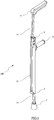
FIG. 1 is a perspective view of a cane in accordance with the preferred embodiment of the present invention; -
FIG. 2 is another perspective view of the cane shown inFIG. 1 , taken from another angle; -
FIG. 3 is a partial exploded perspective view of the cane shown inFIG. 1 ; -
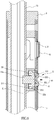
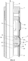
FIGS. 4-10 are partial enlarged cross-sectional views of the cane shown inFIG. 1 , showing the process of adjusting the cane; -
FIG. 11 illustrates that the cane inFIG. 1 is extended to a desired length; and -
FIG. 12 is a prior art. - Referring to the drawings to
FIGS. 1-11 , acane 100 is provided in accordance with the preferred embodiment of the present invention. As shown inFIG. 1 or2 , thecane 100 is an underarm auxiliary crutch and generally includes atube 11, anupper extension rod 12 telescopically mounted within an upper end of thetube 11, alower extension rod 13 telescopically mounted within a lower end of thetube 11, anunderarm support 6 laterally extending from a top end of theupper extension rod 12, ahandle 5 laterally extending from a side of thetube 11 and arubber tip 7 mounted to a bottom end of thelower extension rod 13. - Referring to
FIG. 3 , thetube 11 defines afirst aperture 111 and asecond aperture 112 spaced a distance apart in an upper side thereof. Thesecond aperture 112 of thetube 11 is larger in diameter than thefirst aperture 111 of thetube 11. Preferably, a firstflexible cap 41 is sized and shaped to cover thefirst aperture 111 in thetube 11, and a secondflexible cap 42 is sized and shaped to cover thesecond aperture 112 in thetube 11 for protection. Theupper extension rod 12 defines a plurality ofholes 14 in a side thereof. - Moreover, the
cane 100 further includes acontrol mechanism 2 for controlling movement of thetube 11 and theextension rod 12. There are an identical control mechanism and other two apertures presented at the other end of thetube 11. As it is identical, only theupper control mechanism 2 is described. - As shown in
FIG. 3 , thecontrol mechanism 2 includes acarrier 21, abutton 22 and aspring 23. As shown inFIG. 4 , thecarrier 21 is slidably sandwiched between the inner wall of thetube 11 and the outer wall of theextension rod 12. Thebutton 22 is seated in arecess 211 of thecarrier 21 and includes ahead 222 and apin 221. Thehead 222 of thebutton 22 is provided to be at least partly received in thefirst aperture 112 in thetube 11. Thepin 221 has one end joined to thehead 222, and the other end extends through atransverse bore 212 in a bottom of therecess 211 of thecarrier 21 to be engaged in a selected one 14a of the holes in theextension rod 12. When thecane 100 is in a retracted position, as depicted inFIG. 4 , thepin 221 of thebutton 22 passes through thetransverse bore 212 of thecarrier 21 and into thehole 14a of theextension rod 12. Thespring 23 is assembled around thepin 221 and braced in therecess 211 of thecarrier 23 for normally biasing thebutton 22 toward the inner wall of thetube 11. In particular, thehead 222 of thebutton 22 has a stepped shape with a firstouter shoulder 223 and a secondlarger shoulder 224 corresponding to thefirst aperture 111 and thesecond aperture 112 in thetube 11. - In operation, the
cane 100 is adjusted from the retracted position (FIG. 4 ), for storage, to an extended position (FIG. 5 ), for use. Specifically, thecontrol mechanism 2 together with theextension rod 12 moves from a lower original position (FIG. 4 ) to an upper, first position (FIG. 5 ) where thecontrol mechanism 2 remains positioned in the selectedhole 14a in theextension rod 12 and exposed in thefirst aperture 111 in thetube 11. As shown inFIG. 5 , when thecontrol mechanism 2 is in the first position, thecontrol mechanism 2 has a first end, namely thehead 222, laterally engaged in thefirst aperture 111 in thetube 11 and a second end, namely thepin 221, laterally engaged in the selectedhole 14a in theextension rod 12 such that thetube 11, theextension rod 12 and thecontrol mechanism 2 are prohibited from moving axially with respect to one another. Specifically, thehead 222 of thebutton 22 is partly engaged in thefirst aperture 111 in thetube 11 with its firstouter shoulder 223 abutting against the inner wall of thetube 11. On the other hand, thepin 221 of thebutton 22 is engaged in the selectedhole 14a in theextension rod 12. As such, thecane 100 is extended with a predetermined length and is ready to be used for walking. However, if the user is not satisfied with the length of thecane 100, thecane 100 may be further adjusted as described below. - With reference to
FIG. 6 , by pushing thebutton 22 from outside of the firstflexible cap 41, as indicated by the arrow, thecontrol mechanism 2 may be moved laterally from the first position (FIG. 5 ) to a second position (FIG. 6 ) where the first end of thecontrol mechanism 2, namely thehead 221, is withdrawn from thefirst aperture 111 in thetube 11 such that theextension rod 12 and thecontrol mechanism 2 together are allowed to move axially with respect to thetube 11. That is, thecontrol mechanism 2 is ready to move with theextension rod 12 from the second position (FIG. 6 ) up to a third position (FIG. 8 ) via a transition position (FIG. 7 ) where thecontrol mechanism 2 is exposed in thesecond aperture 112 in thetube 11. More specifically, upon thecontrol mechanism 2 arrives in the transition position, as shown inFIG. 7 , thebutton 22 of thecontrol mechanism 2 is pushed by thespring 23 toward thetube 11 such that thecontrol mechanism 2 laterally moves from the transition position (FIG. 7 ) to the third position (FIG. 8 ) where the first end of thecontrol mechanism 2, namely thehead 222, is engaged in thesecond aperture 112 of thetube 11 and the second end of thecontrol mechanism 2, namely thepin 221, is completely withdrawn from the selectedhole 14a. Thus, theextension rod 12 is released from thecontrol mechanism 2 and therefore allowed to move axially with respect to thecontrol mechanism 2 and thetube 11. More specifically, thehead 222 of thebutton 22 is partly engaged in thesecond aperture 112 in thetube 11 with the secondenlarged shoulder 224 abutting against the inner wall of thetube 11. Since theextension rod 12 is released from thecontrol mechanism 2, thecane 100 is allowed to be adjusted to change its total length by moving theextension rod 12. For example, theextension rod 12 may be pulled upward or outward, as shown inFIG. 11 , with respect to thecontrol mechanism 2 and thetube 11 to a desired position where a newselected hole 14b of theextension rod 12, instead of thehole 14a, is aligned with thepin 221 of thebutton 22 of thecontrol mechanism 2, as depicted inFIG. 9 . - In order to prevent the
extension rod 12 from being completely detached from thetube 11, astop member 3 is provided to be mounted on the upper end of thetube 11 to block thecontrol mechanism 2 so that theextension rod 12 will not come off thetube 11. As best seen inFIG. 3 , thestop member 3 defines, from top to bottom, apassage 31 through which theextension rod 12 extends. - As shown in
FIG. 9 , thecontrol mechanism 2 may then be pushed inward from outside of the secondflexible cap 42, as indicated by the arrow, to have thepin 221 of thebutton 22 be re-engaged in the new selectedhole 14b in theextension rod 12 and have thehead 222 of thebutton 22 withdrawn from thesecond aperture 112 in thetube 11. This means that thecane 100 is reset to have a desired total length. Theextension rod 12 together with thecontrol mechanism 2 may then be pushed downward to have the new selectedhole 14b and thecontrol mechanism 2 together laterally aligned with thefirst aperture 111 in thetube 11, as shown inFIG. 10 , for use. At this time, the total length of thecane 100 has been changed to the desired total length. Alternatively, theextension rod 12 together with thecontrol mechanism 2 may pass by thefirst aperture 111 in thetube 11 and down to a lowest position to have thecane 100 be retracted for storage. It is understood that the next time thecane 100 is extended for use, thecane 100 can be extended directly to the desired total length as thecane 100 memories the user's desire. - Preferably, the
extension rod 12 is formed thereon with a plurality of alignment marks 15, as shown inFIG. 3 , spaced along a length of theextension rod 12 and corresponding to theholes 14 in theextension rod 12 to facilitate adjust the length of thecane 100. If one of the alignment marks is aligned with a top edge of thestop member 3, therespective hole 14 in theextension rod 12 is aligned with thesecond aperture 112 in thetube 11. This helps for alignment between the new selectedhole 14b in theextension rod 12 and thepin 221 of thebutton 22 of thecontrol mechanism 2 which is in line with thesecond aperture 112 in thetube 11 , as shown inFIG. 9 . - It is to be understood that the disclosed embodiments are illustrative in nature and the invention is not to be limited to any one or more embodiments except as set forth in the following claims.
Claims (9)
- A cane comprising a tube (11) defining a first aperture (111) and a second aperture (112) spaced in a side thereof and being larger in diameter than the first aperture (111); an extension rod (12) telescopically mounted within one end of the tube (11) and defining a plurality of holes (14) in a side thereof; and a control mechanism (2),
wherein the control mechanism (2) is disposed in between an inner wall of the tube (11) and an outer wall of the extension rod (12), and is movable to a first position where the control mechanism (2) has a first end laterally engaged in the first aperture (111) in the tube (11) and a second end laterally engaged in the selected hole (14) in the extension rod (12) such that the tube (11), the extension rod (12) and the control mechanism (2) are prohibited from moving axially with respect to one another; a second position where the first end of the control mechanism (2) is withdrawn from the first aperture (111) in the tube (11) such that the extension rod (12) and the control mechanism (2) together are allowed to move axially with respect to the tube (11), the control mechanism (2) being movable laterally from the first position to the second position; and a third position where the first end of the control mechanism (2) is engaged in the second aperture (112) of the tube (11) and the second end of the control mechanism (2) is withdrawn from the selected hole (14) such that the extension rod (12) is allowed to move axially with respect to the control mechanism (2) and the tube (11) ;
wherein the control mechanism (2) together with the extension rod (12) is axially movable from the second position to a transition position to permit the control mechanism (2) laterally moving to the third position,
wherein the control mechanism (2) includes a carrier (21) having a transverse bore (212) and sandwiched between the inner wall of the tube (11) and the outer wall of the extension rod (12), a button (22) seated in the carrier (21), and a spring (23) disposed in the carrier (21) for normally biasing the button (22) toward the inner wall of the tube (11);
characterized in that the button (22) consists of a head (222) and a pin (221), wherein the head (222) is configured to be at least partly received in the first aperture (111) in the tube (11), the head (222) having a stepped shape with a first outer shoulder (223) and a second larger shoulder (224), and the pin (221) has one end joined to the head (222) and the other end extending through the transverse bore (212) in the carrier (21), the spring (23) being mounted about the pin (221) and interposed between the carrier (21) and the head (222), such that when the control mechanism (2) is in the first position, the other end of the pin (221) of the button (22) is engaged in the selected hole (14) in the extension rod (12) and the head of the button (22) is partly engaged in the first aperture (111) in the tube (11) with the first outer shoulder (223) abutting against the inner wall of the tube (11); and when the control mechanism (2) is in the third position, the head (222) of the button (22) is partly engaged in the second aperture (112) in the tube (11) with the second enlarged shoulder (224) abutting against the inner wall of the tube (11). - The cane of claim 1, characterized in that the cane further comprises a stop member (3) mounted on the end of the tube (11) to prevent the extension rod (12) from being detached from the tube (11); the stop member (3) has a passage (31) defined from top to bottom thereof; and the extension rod (12) extends though the passage (31) of the stop member (3).
- The cane of claim 2, characterized in that the extension rod (12) is formed thereon with a plurality of alignment marks (15) spaced along a length of the extension rod (12) and corresponding to the holes (14) in the extension rod (12) such that if one of the alignment marks (15) is aligned with a top edge of the stop member (3), the respective hole (14) in the extension rod (12) is aligned with the second aperture (112) in the tube (11).
- The cane of claim 1, characterized in that the cane further comprises a first flexible cap (41) sized and shaped to cover the first aperture (111) in the tube (11).
- The cane of claim 4, characterized in that the cane further comprises a second flexible cap (42) sized and shaped to cover the second aperture (112) in the tube (11).
- The cane of claim 1, characterized in that the cane further comprises an underarm support (6) laterally extending from a top end of the extension rod (12).
- The cane of claim 6, characterized in that the cane further comprises a handle (5) laterally extending from a side of the tube (11).
- The cane of claim 1, characterized in that the cane further comprises another extension rod (12) telescopically mounted within the other end of the tube (11).
- The cane of claim 8, characterized in that the cane further comprises a rubber tip (7) mounted to a bottom end of the another extension rod (12).
Priority Applications (1)
| Application Number | Priority Date | Filing Date | Title |
|---|---|---|---|
| EP13177118.0A EP2687197B1 (en) | 2013-07-18 | 2013-07-18 | Adjustable cane with memory function |
Applications Claiming Priority (1)
| Application Number | Priority Date | Filing Date | Title |
|---|---|---|---|
| EP13177118.0A EP2687197B1 (en) | 2013-07-18 | 2013-07-18 | Adjustable cane with memory function |
Publications (2)
| Publication Number | Publication Date |
|---|---|
| EP2687197A1 EP2687197A1 (en) | 2014-01-22 |
| EP2687197B1 true EP2687197B1 (en) | 2019-03-27 |
Family
ID=48877023
Family Applications (1)
| Application Number | Title | Priority Date | Filing Date |
|---|---|---|---|
| EP13177118.0A Not-in-force EP2687197B1 (en) | 2013-07-18 | 2013-07-18 | Adjustable cane with memory function |
Country Status (1)
| Country | Link |
|---|---|
| EP (1) | EP2687197B1 (en) |
Families Citing this family (2)
| Publication number | Priority date | Publication date | Assignee | Title |
|---|---|---|---|---|
| CN105310858B (en) * | 2015-03-25 | 2017-10-24 | 弗兰克·小青·张 | Intelligent shoulder and intelligent wearable upper part of body support auxiliary system |
| CN111544265B (en) * | 2020-05-13 | 2022-01-11 | 南通大学 | An orthopedic adjustable universal tuck |
Family Cites Families (5)
| Publication number | Priority date | Publication date | Assignee | Title |
|---|---|---|---|---|
| DE2819717A1 (en) * | 1978-05-05 | 1979-11-15 | Mekanoverken Ab | Telescopic crutch with locking device - consisting of sprung pin which projects through registering holes in column tubes (SW 12.6.78) |
| US4616668A (en) * | 1984-10-16 | 1986-10-14 | Tubular Fabricators, Industry, Inc. | Invalid device having interlocking telescoping members |
| US4809725A (en) * | 1986-02-12 | 1989-03-07 | Patrick Champigny | Telescopic crutch and walking stick |
| TWM448169U (en) * | 2012-07-18 | 2013-03-11 | Footwear & Recreation Technology Res Inst | Foldable crutch with memory function |
| JP3185401U (en) * | 2013-06-03 | 2013-08-15 | 財團法人鞋類曁運動休閑科技研發中心 | Telescopic cane with length memory function |
-
2013
- 2013-07-18 EP EP13177118.0A patent/EP2687197B1/en not_active Not-in-force
Non-Patent Citations (1)
| Title |
|---|
| None * |
Also Published As
| Publication number | Publication date |
|---|---|
| EP2687197A1 (en) | 2014-01-22 |
Similar Documents
| Publication | Publication Date | Title |
|---|---|---|
| US9192213B2 (en) | Adjustable cane with memory function | |
| US7503337B1 (en) | Grip tip assembly for walking aids | |
| US10492577B2 (en) | Hinged walking cane | |
| US8464737B2 (en) | Stabilizer support for crutches and/or walking sticks | |
| US8919362B1 (en) | Walking cane with platform | |
| US2960095A (en) | Convertible cane-crutch | |
| EP3581754B1 (en) | Telescopic ladder assembly | |
| US20040188575A1 (en) | Stabiliser with telescopic rods for tripods and the like | |
| US20110048478A1 (en) | Automatic Umbrella with a Closing Signaling Device | |
| EP1641668B1 (en) | Locking device for a telescopic stem of a trolley | |
| US10092068B2 (en) | Length adjustment device | |
| US20140070592A1 (en) | Adjustable structure for the footrest ring of a chair | |
| US3417765A (en) | Telescoping and longitudinally adjustable crutch | |
| ITMI992510A1 (en) | SELF-REGULATING WALKING STICK | |
| EP2687197A1 (en) | Adjustable cane with memory function | |
| US20020074774A1 (en) | Adjustable handle of umbrella stroller by telescoping and swiveling | |
| KR102258526B1 (en) | Apparatus for Adjusting Length | |
| KR101707129B1 (en) | Length adjustable walking assistance device | |
| US74933A (en) | Isaac e | |
| CN103181663B (en) | Combined walking pole | |
| US8979188B2 (en) | Collapsible single leg sitting device | |
| EP3847922B1 (en) | Length adjustment device | |
| EP1733948A2 (en) | Locking device used in combination with frame assembly | |
| EP1892339A1 (en) | Adjustable support for a shower head | |
| TWM551012U (en) | Length-memorizing and adjusting handrail rod for assistive devices |
Legal Events
| Date | Code | Title | Description |
|---|---|---|---|
| PUAI | Public reference made under article 153(3) epc to a published international application that has entered the european phase |
Free format text: ORIGINAL CODE: 0009012 |
|
| 17P | Request for examination filed |
Effective date: 20130819 |
|
| AK | Designated contracting states |
Kind code of ref document: A1 Designated state(s): AL AT BE BG CH CY CZ DE DK EE ES FI FR GB GR HR HU IE IS IT LI LT LU LV MC MK MT NL NO PL PT RO RS SE SI SK SM TR |
|
| AX | Request for extension of the european patent |
Extension state: BA ME |
|
| 17Q | First examination report despatched |
Effective date: 20160426 |
|
| GRAP | Despatch of communication of intention to grant a patent |
Free format text: ORIGINAL CODE: EPIDOSNIGR1 |
|
| STAA | Information on the status of an ep patent application or granted ep patent |
Free format text: STATUS: GRANT OF PATENT IS INTENDED |
|
| INTG | Intention to grant announced |
Effective date: 20181011 |
|
| GRAS | Grant fee paid |
Free format text: ORIGINAL CODE: EPIDOSNIGR3 |
|
| GRAA | (expected) grant |
Free format text: ORIGINAL CODE: 0009210 |
|
| STAA | Information on the status of an ep patent application or granted ep patent |
Free format text: STATUS: THE PATENT HAS BEEN GRANTED |
|
| AK | Designated contracting states |
Kind code of ref document: B1 Designated state(s): AL AT BE BG CH CY CZ DE DK EE ES FI FR GB GR HR HU IE IS IT LI LT LU LV MC MK MT NL NO PL PT RO RS SE SI SK SM TR |
|
| REG | Reference to a national code |
Ref country code: GB Ref legal event code: FG4D |
|
| REG | Reference to a national code |
Ref country code: CH Ref legal event code: EP |
|
| REG | Reference to a national code |
Ref country code: AT Ref legal event code: REF Ref document number: 1112147 Country of ref document: AT Kind code of ref document: T Effective date: 20190415 |
|
| REG | Reference to a national code |
Ref country code: IE Ref legal event code: FG4D |
|
| REG | Reference to a national code |
Ref country code: DE Ref legal event code: R096 Ref document number: 602013052844 Country of ref document: DE |
|
| PG25 | Lapsed in a contracting state [announced via postgrant information from national office to epo] |
Ref country code: SE Free format text: LAPSE BECAUSE OF FAILURE TO SUBMIT A TRANSLATION OF THE DESCRIPTION OR TO PAY THE FEE WITHIN THE PRESCRIBED TIME-LIMIT Effective date: 20190327 Ref country code: LT Free format text: LAPSE BECAUSE OF FAILURE TO SUBMIT A TRANSLATION OF THE DESCRIPTION OR TO PAY THE FEE WITHIN THE PRESCRIBED TIME-LIMIT Effective date: 20190327 Ref country code: NO Free format text: LAPSE BECAUSE OF FAILURE TO SUBMIT A TRANSLATION OF THE DESCRIPTION OR TO PAY THE FEE WITHIN THE PRESCRIBED TIME-LIMIT Effective date: 20190627 Ref country code: FI Free format text: LAPSE BECAUSE OF FAILURE TO SUBMIT A TRANSLATION OF THE DESCRIPTION OR TO PAY THE FEE WITHIN THE PRESCRIBED TIME-LIMIT Effective date: 20190327 |
|
| REG | Reference to a national code |
Ref country code: NL Ref legal event code: MP Effective date: 20190327 |
|
| PG25 | Lapsed in a contracting state [announced via postgrant information from national office to epo] |
Ref country code: BG Free format text: LAPSE BECAUSE OF FAILURE TO SUBMIT A TRANSLATION OF THE DESCRIPTION OR TO PAY THE FEE WITHIN THE PRESCRIBED TIME-LIMIT Effective date: 20190627 Ref country code: RS Free format text: LAPSE BECAUSE OF FAILURE TO SUBMIT A TRANSLATION OF THE DESCRIPTION OR TO PAY THE FEE WITHIN THE PRESCRIBED TIME-LIMIT Effective date: 20190327 Ref country code: HR Free format text: LAPSE BECAUSE OF FAILURE TO SUBMIT A TRANSLATION OF THE DESCRIPTION OR TO PAY THE FEE WITHIN THE PRESCRIBED TIME-LIMIT Effective date: 20190327 Ref country code: LV Free format text: LAPSE BECAUSE OF FAILURE TO SUBMIT A TRANSLATION OF THE DESCRIPTION OR TO PAY THE FEE WITHIN THE PRESCRIBED TIME-LIMIT Effective date: 20190327 Ref country code: GR Free format text: LAPSE BECAUSE OF FAILURE TO SUBMIT A TRANSLATION OF THE DESCRIPTION OR TO PAY THE FEE WITHIN THE PRESCRIBED TIME-LIMIT Effective date: 20190628 Ref country code: NL Free format text: LAPSE BECAUSE OF FAILURE TO SUBMIT A TRANSLATION OF THE DESCRIPTION OR TO PAY THE FEE WITHIN THE PRESCRIBED TIME-LIMIT Effective date: 20190327 |
|
| REG | Reference to a national code |
Ref country code: AT Ref legal event code: MK05 Ref document number: 1112147 Country of ref document: AT Kind code of ref document: T Effective date: 20190327 |
|
| PG25 | Lapsed in a contracting state [announced via postgrant information from national office to epo] |
Ref country code: PT Free format text: LAPSE BECAUSE OF FAILURE TO SUBMIT A TRANSLATION OF THE DESCRIPTION OR TO PAY THE FEE WITHIN THE PRESCRIBED TIME-LIMIT Effective date: 20190727 Ref country code: AL Free format text: LAPSE BECAUSE OF FAILURE TO SUBMIT A TRANSLATION OF THE DESCRIPTION OR TO PAY THE FEE WITHIN THE PRESCRIBED TIME-LIMIT Effective date: 20190327 Ref country code: ES Free format text: LAPSE BECAUSE OF FAILURE TO SUBMIT A TRANSLATION OF THE DESCRIPTION OR TO PAY THE FEE WITHIN THE PRESCRIBED TIME-LIMIT Effective date: 20190327 Ref country code: SK Free format text: LAPSE BECAUSE OF FAILURE TO SUBMIT A TRANSLATION OF THE DESCRIPTION OR TO PAY THE FEE WITHIN THE PRESCRIBED TIME-LIMIT Effective date: 20190327 Ref country code: CZ Free format text: LAPSE BECAUSE OF FAILURE TO SUBMIT A TRANSLATION OF THE DESCRIPTION OR TO PAY THE FEE WITHIN THE PRESCRIBED TIME-LIMIT Effective date: 20190327 Ref country code: IT Free format text: LAPSE BECAUSE OF FAILURE TO SUBMIT A TRANSLATION OF THE DESCRIPTION OR TO PAY THE FEE WITHIN THE PRESCRIBED TIME-LIMIT Effective date: 20190327 Ref country code: RO Free format text: LAPSE BECAUSE OF FAILURE TO SUBMIT A TRANSLATION OF THE DESCRIPTION OR TO PAY THE FEE WITHIN THE PRESCRIBED TIME-LIMIT Effective date: 20190327 Ref country code: EE Free format text: LAPSE BECAUSE OF FAILURE TO SUBMIT A TRANSLATION OF THE DESCRIPTION OR TO PAY THE FEE WITHIN THE PRESCRIBED TIME-LIMIT Effective date: 20190327 |
|
| PG25 | Lapsed in a contracting state [announced via postgrant information from national office to epo] |
Ref country code: PL Free format text: LAPSE BECAUSE OF FAILURE TO SUBMIT A TRANSLATION OF THE DESCRIPTION OR TO PAY THE FEE WITHIN THE PRESCRIBED TIME-LIMIT Effective date: 20190327 Ref country code: SM Free format text: LAPSE BECAUSE OF FAILURE TO SUBMIT A TRANSLATION OF THE DESCRIPTION OR TO PAY THE FEE WITHIN THE PRESCRIBED TIME-LIMIT Effective date: 20190327 |
|
| PG25 | Lapsed in a contracting state [announced via postgrant information from national office to epo] |
Ref country code: IS Free format text: LAPSE BECAUSE OF FAILURE TO SUBMIT A TRANSLATION OF THE DESCRIPTION OR TO PAY THE FEE WITHIN THE PRESCRIBED TIME-LIMIT Effective date: 20190727 Ref country code: AT Free format text: LAPSE BECAUSE OF FAILURE TO SUBMIT A TRANSLATION OF THE DESCRIPTION OR TO PAY THE FEE WITHIN THE PRESCRIBED TIME-LIMIT Effective date: 20190327 |
|
| REG | Reference to a national code |
Ref country code: DE Ref legal event code: R097 Ref document number: 602013052844 Country of ref document: DE |
|
| PG25 | Lapsed in a contracting state [announced via postgrant information from national office to epo] |
Ref country code: DK Free format text: LAPSE BECAUSE OF FAILURE TO SUBMIT A TRANSLATION OF THE DESCRIPTION OR TO PAY THE FEE WITHIN THE PRESCRIBED TIME-LIMIT Effective date: 20190327 |
|
| PLBE | No opposition filed within time limit |
Free format text: ORIGINAL CODE: 0009261 |
|
| STAA | Information on the status of an ep patent application or granted ep patent |
Free format text: STATUS: NO OPPOSITION FILED WITHIN TIME LIMIT |
|
| PG25 | Lapsed in a contracting state [announced via postgrant information from national office to epo] |
Ref country code: MC Free format text: LAPSE BECAUSE OF FAILURE TO SUBMIT A TRANSLATION OF THE DESCRIPTION OR TO PAY THE FEE WITHIN THE PRESCRIBED TIME-LIMIT Effective date: 20190327 Ref country code: SI Free format text: LAPSE BECAUSE OF FAILURE TO SUBMIT A TRANSLATION OF THE DESCRIPTION OR TO PAY THE FEE WITHIN THE PRESCRIBED TIME-LIMIT Effective date: 20190327 |
|
| REG | Reference to a national code |
Ref country code: CH Ref legal event code: PL |
|
| 26N | No opposition filed |
Effective date: 20200103 |
|
| GBPC | Gb: european patent ceased through non-payment of renewal fee |
Effective date: 20190718 |
|
| PG25 | Lapsed in a contracting state [announced via postgrant information from national office to epo] |
Ref country code: TR Free format text: LAPSE BECAUSE OF FAILURE TO SUBMIT A TRANSLATION OF THE DESCRIPTION OR TO PAY THE FEE WITHIN THE PRESCRIBED TIME-LIMIT Effective date: 20190327 |
|
| REG | Reference to a national code |
Ref country code: BE Ref legal event code: MM Effective date: 20190731 |
|
| PG25 | Lapsed in a contracting state [announced via postgrant information from national office to epo] |
Ref country code: GB Free format text: LAPSE BECAUSE OF NON-PAYMENT OF DUE FEES Effective date: 20190718 |
|
| PG25 | Lapsed in a contracting state [announced via postgrant information from national office to epo] |
Ref country code: BE Free format text: LAPSE BECAUSE OF NON-PAYMENT OF DUE FEES Effective date: 20190731 Ref country code: LI Free format text: LAPSE BECAUSE OF NON-PAYMENT OF DUE FEES Effective date: 20190731 Ref country code: LU Free format text: LAPSE BECAUSE OF NON-PAYMENT OF DUE FEES Effective date: 20190718 Ref country code: CH Free format text: LAPSE BECAUSE OF NON-PAYMENT OF DUE FEES Effective date: 20190731 |
|
| PG25 | Lapsed in a contracting state [announced via postgrant information from national office to epo] |
Ref country code: FR Free format text: LAPSE BECAUSE OF NON-PAYMENT OF DUE FEES Effective date: 20190731 |
|
| PG25 | Lapsed in a contracting state [announced via postgrant information from national office to epo] |
Ref country code: IE Free format text: LAPSE BECAUSE OF NON-PAYMENT OF DUE FEES Effective date: 20190718 |
|
| PG25 | Lapsed in a contracting state [announced via postgrant information from national office to epo] |
Ref country code: CY Free format text: LAPSE BECAUSE OF FAILURE TO SUBMIT A TRANSLATION OF THE DESCRIPTION OR TO PAY THE FEE WITHIN THE PRESCRIBED TIME-LIMIT Effective date: 20190327 |
|
| PG25 | Lapsed in a contracting state [announced via postgrant information from national office to epo] |
Ref country code: HU Free format text: LAPSE BECAUSE OF FAILURE TO SUBMIT A TRANSLATION OF THE DESCRIPTION OR TO PAY THE FEE WITHIN THE PRESCRIBED TIME-LIMIT; INVALID AB INITIO Effective date: 20130718 Ref country code: MT Free format text: LAPSE BECAUSE OF FAILURE TO SUBMIT A TRANSLATION OF THE DESCRIPTION OR TO PAY THE FEE WITHIN THE PRESCRIBED TIME-LIMIT Effective date: 20190327 |
|
| PG25 | Lapsed in a contracting state [announced via postgrant information from national office to epo] |
Ref country code: MK Free format text: LAPSE BECAUSE OF FAILURE TO SUBMIT A TRANSLATION OF THE DESCRIPTION OR TO PAY THE FEE WITHIN THE PRESCRIBED TIME-LIMIT Effective date: 20190327 |
|
| PGFP | Annual fee paid to national office [announced via postgrant information from national office to epo] |
Ref country code: DE Payment date: 20230613 Year of fee payment: 11 |
|
| REG | Reference to a national code |
Ref country code: DE Ref legal event code: R119 Ref document number: 602013052844 Country of ref document: DE |
|
| PG25 | Lapsed in a contracting state [announced via postgrant information from national office to epo] |
Ref country code: DE Free format text: LAPSE BECAUSE OF NON-PAYMENT OF DUE FEES Effective date: 20250201 |