EP2687076A1 - Landwirtschaftliche Verteilmaschine - Google Patents
Landwirtschaftliche Verteilmaschine Download PDFInfo
- Publication number
- EP2687076A1 EP2687076A1 EP13401054.5A EP13401054A EP2687076A1 EP 2687076 A1 EP2687076 A1 EP 2687076A1 EP 13401054 A EP13401054 A EP 13401054A EP 2687076 A1 EP2687076 A1 EP 2687076A1
- Authority
- EP
- European Patent Office
- Prior art keywords
- elements
- container element
- attachment
- embossing
- container
- Prior art date
- Legal status (The legal status is an assumption and is not a legal conclusion. Google has not performed a legal analysis and makes no representation as to the accuracy of the status listed.)
- Granted
Links
Images



Classifications
-
- A—HUMAN NECESSITIES
- A01—AGRICULTURE; FORESTRY; ANIMAL HUSBANDRY; HUNTING; TRAPPING; FISHING
- A01C—PLANTING; SOWING; FERTILISING
- A01C15/00—Fertiliser distributors
- A01C15/005—Undercarriages, tanks, hoppers, stirrers specially adapted for seeders or fertiliser distributors
- A01C15/006—Hoppers
-
- A—HUMAN NECESSITIES
- A01—AGRICULTURE; FORESTRY; ANIMAL HUSBANDRY; HUNTING; TRAPPING; FISHING
- A01C—PLANTING; SOWING; FERTILISING
- A01C17/00—Fertilisers or seeders with centrifugal wheels
- A01C17/001—Centrifugal throwing devices with a vertical axis
Definitions
- the invention relates to an agricultural distribution machine according to the preamble of claim 1.
- the storage container and the attachment container element of this distribution machine consists of individual wall elements which have flange regions formed by folds and are to be connected to one another via these. Because of these flange portions formed by folds, it is necessary that the individual edge regions must be designed to extend in a straight line. As a result, the design of the attachment elements or their flange is very limited.
- the invention is based on the object to provide flange areas in a simple manner, which are formed adapted to each other in a simple manner.
- the formations are formed at least the corner regions of the lower flange portions of the top container element to adapt to the contour of the upper peripheral portion of the reservoir tank as embossing elements, that the other not created by embossing moldings for the design of the attachment container element are created by folding of portions of the wall elements of the attachment container element.
- the Flansch Kunststoffes be created by embossing and designed to match the shape and design of the upper flange portion of the reservoir sufficiently accurately adapted.
- a high accuracy of fit of the flange to be joined together is achieved.
- An adapted configuration of the flange regions of the side walls can be achieved in that the lower regions of the attachment container element are formed as curves formed on the side walls of the deployment container element by embossing for adaptation to the contour of the upper circumferential region of the base container.
- the upright corner regions of the side wall elements of the attachment element have flange elements produced by bending for connection to the front and / or rear wall elements of the deployment container element.
- the agricultural device formed as a distributor for discharging granular material, for example mineral fertilizer is designed in the embodiment as a centrifugal fertilizer spreader.
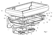
- the spreader has a basic reservoir 2 carried by frame elements 1, which opens into two outlet funnels 3.
- the frame 1 is equipped on its front side with known and therefore in a manner not shown with three-point coupling elements for attachment to a three-point hitch of a tractor.
- the reservoir 2 has two through roof-shaped central part 4 from each other divided discharge funnel 3.
- fasteners for the arrangement of the outlet funnel down closing and adjustable metering devices 5 are arranged.
- About the metering devices 5 located in the reservoir 2 material is supplied in adjustable amounts arranged below the metering devices 5 and rotatably driven centrifugal discs 6.
- a container element 11 comprising several individual wall elements 8 and 9 and having a lower flange region 10 can be arranged.
- the upper edge region 7 of the storage container 2 has rounded edge regions 13 in its corner regions 12. This upper edge region 7 of the storage container 2 serves as a flange region for flanging the attachment container element 11.
- the attachment container element 11 is formed by two mirror-image formed front and rear walls 8 and two likewise mirror-inverted side walls 9, which are interconnected by means of suitable fastening means. In the exemplary embodiment, they are the connecting means, the flange elements and these interconnecting screws formed. It is also possible to weld the individual sub-elements 8 and 9 of the attachment container element 11 together.
- the flange portions 14 produced by a stamping tool.
- the flat sheets according to Fig. 2 and 3 according to the illustration Fig. 4 and 5 for molding of the flange elements 15 and 16.
- embossing elements 15 and 16 are formed as embossing elements 15 and 16, like the Fig. 4 and 5 demonstrate.
- embossing moldings 17 for the design of the essay container element 11 in their straight areas are created by means of bending of portions of the wall elements of the essay container element 11.
- the lower portions of the lancing element 11 formed as formed on the side walls 9 of the attachment element 11 by embossing curves 15 for adaptation to the contour of the upper peripheral region 7 of the base container 2.
- the upright corner portions 18 of the side wall members 9 of the attachment member 11 are flange-formed flange members for connection to the front and rear wall members 8 of the attachment container member 11.
- the other folds 19, which run in a straight line, are produced by conventional folding.
- a cover 2 is arranged between the upper reservoir portion 7 and the lower portion of the attachment element 11.
Landscapes
- Life Sciences & Earth Sciences (AREA)
- Soil Sciences (AREA)
- Environmental Sciences (AREA)
- Catching Or Destruction (AREA)
- Fertilizing (AREA)
- Packging For Living Organisms, Food Or Medicinal Products That Are Sensitive To Environmental Conditiond (AREA)
Abstract
Description
- Die Erfindung betrifft eine landwirtschaftliche Verteilmaschine gemäß des Oberbegriffes des Patentanspruches 1.
- Eine derartige landwirtschaftliche Verteilmaschine ist in
DE 697 01 887 T3 beschrieben. Der Vorratsbehälter und das Aufsatzbehälterelement dieser Verteilmaschine besteht aus einzelnen Wandelementen, die durch Abkantungen gebildete Flanschbereiche aufweisen und über diese miteinander zu verbinden sind. Aufgrund dieser durch Abkantungen gebildeten Flanschbereiche ist es erforderlich, dass die einzelnen Randbereiche geradlinig verlaufend ausgebildet sein müssen. Hierdurch ist die Gestaltung der Aufsatzelemente bzw. deren Flanschbereiche sehr eingeschränkt. - Durch die
DE 10 2010 000 298 A1 ist eine weitere landwirtschaftliche Verteilmaschine bekannt geworden, deren Grundgehälter durch Tiefziehvorgänge hergestellt ist. Hierdurch ist es möglich, die Eckbereiche abgerundet auszubilden. Problematisch ist nun, an die oberen, gerundeten Randbereiche ein sich dicht anschließendes Aufsatzbehälterelement aufzusetzen. - Der Erfindung liegt die Aufgabe zu Grunde, in einfacher Weise Flanschbereiche zu schaffen, die in einfacher Weise einander angepasst ausgebildet sind.
- Diese Aufgabe wird erfindungsgemäß dadurch gelöst, dass die Ausformungen zumindest der Eckbereiche der unteren Flanschbereiche des Aufsatzbehälterelementes zur Anpassung an die Kontur des oberen umlaufenden Bereiches des Grundvorratsbehälters als Prägeelemente ausgebildet sind, dass die übrigen nicht durch Prägung geschaffenen Ausformungen zur Ausgestaltung des Aufsatzbehälterelementes mittels Abkantung von Teilbereichen der Wandelemente des Aufsatzbehälterelementes geschaffen sind.
- Infolge dieser Maßnahmen werden die Flanschbereiches durch Prägung geschaffen und entsprechend an die Ausformung und Ausgestaltung der oberen Flanschbereiches des Vorratsbehälters ausreichend genau angepasst ausgebildet. Somit wird eine hohe Passgenauigkeit der miteinander zu verbindenden Flanschbereiche erreicht.
- Eine angepasste Ausgestaltung der Flanschbereiche der Seitenwände lässt sich dadurch erreichen, dass die unteren Bereiche des Aufsatzbehälterelementes als sich an die Seitenwände des Aussatzbehälterelementes durch Prägung angeformte Rundungen zur Anpassung an die Kontur des oberen umlaufenden Bereiches des Grundbehälters ausgebildet sind.
- Um die aufrechten Eckbereiche der Seitenwandelemente des Aufsatzelementes in einfacher Weise ausgestalten zu können, ist vorgesehen, dass die aufrechten Eckbereiche der seitlichen Wandelemente des Aufsatzelementes durch Abkantung hergestellte Flanschelemente zur Verbindung mit den vorderen und/oder hinteren Wandelementen des Aussatzbehälterelementes aufweisen.
- Weitere Einzelheiten der Erfindung sind der Beispielsbeschreibung zu entnehmen. Die Zeichnungen zeigen
- Fig.1
- die als Schleuderstreuer ausgebildete landwirtschaftliche Verteilmaschine mit Vorratsbehälter und Aufsatzbehälterelement in perspektivischer Darstellung,
- Fig. 2
- die Verteilmaschine gemäß
Fig. 1 , wobei das Aufsatzelement von dem oberen Bereich des Vorratsbehälters abgenommen dargestellt ist. - Fig. 3
- eine Seitenwand des Aufsatzbehälterelementes vor den Präge- und Abgabenvorgängen in perspektivischer Darstellung,
- Fig. 4
- die Seitenwand gemäß
Fig. 3 in Seitenansicht, - Fig. 5
- die Seitenwand nach dem Prägevorgang zur Anformung des unteren Flanschbereiches in perspektivischer Darstellung,
- Fig. 6
- die Seitenwand mit dem angeprägten Flanschbereich in Seitenansicht,
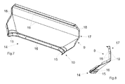
- Fig. 7
- die Seitenwand nach den Präge unter den Abgangvorgängen zur Anformung der verschiedenen Flanschbereiche in perspektivischer Darstellung und
- Fig. 8
- die Seitenwand gemäß
Fig. 7 in Seitenansicht. - Die als Verteilmaschine gebildete landwirtschaftliche Vorrichtung zum Ausbringen von körnigem Material, beispielsweise Mineraldünger ist im Ausführungsbeispiel als Schleuderdüngerstreuer ausgestaltet. Der Streuer weist einen von Rahmenelementen 1 getragenen Grundvorratsbehälter 2 auf, der in zwei Auslauftrichter 3 ausmündet. Der Rahmen 1 ist auf seiner Vorderseite mit bekannten und daher in nicht dargestellter Weise mit Dreipunktkupplungselementen zum Anbau an einen Dreipunktkraftheber eines Ackerschlepper ausgestattet. Der Vorratsbehälter 2 weist zwei durch ein dachförmiges Mittelteil 4 voneinander geteilte Auslauftrichter 3 auf. An den unteren Enden der Auslauftrichter 3 sind Befestigungselemente für die Anordnung der die Auslauftrichter nach unten verschließende und einstellbare Dosiervorrichtungen 5 angeordnet. Über die Dosiervorrichtungen 5 wird das sich in dem Vorratsbehälter 2 befindliche Material in einstellbaren Mengen den unterhalb der Dosiervorrichtungen 5 angeordneten und rotierend angetriebenen Schleuderscheiben 6 zugeleitet.
- An dem oberen umlaufenden Bereich 7 des Grundvorratsbehälters 2 lässt sich ein aus mehreren einzelnen Wandelementen 8 und 9zusammengesetztes und einen unteren Flanschbereich 10 aufweisendes Aufsatzbehälterelement 11 anordnen. Der obere Randbereich 7 des Vorratsbehälters 2 weist in seinen Eckbereichen 12 abgerundete Randbereiche 13 auf. Dieser obere Randbereich 7 des Vorratsbehälters 2 dient als Flanschbereich zum Anflanschen des Aufsatzbehälterelementes 11.
- Das Aufsatzbehälterelement 11 wird durch zwei spiegelbildlich ausgebildete Vorder- und Rückwände 8 und zwei ebenfalls spiegelbildlich ausgebildete Seitenwände 9 gebildet, die mittels geeigneter Befestigungsmittel miteinander verbunden sind. Im Ausführungsbeispiel sind sie die Verbindungsmittel die Flanschelemente und diese miteinander verbindende Schrauben ausgebildet. Ebenfalls ist es möglich, die einzelnen Teilelemente 8 und 9 des Aufsatzbehälterelementes 11 miteinander zu verschweißen.
- Um in die unteren Bereiche 14 der Seitenwände 9 an die oberen Randbereiche 7 des Vorratsbehälters 2, insbesondere den abgerundeten Bereichen 13 des Vorratsbehälters 2 entsprechend anzupassen, damit die Flanschbereiche 7 und 14 konturengenau entsprechend ausgebildet sind, werden die Flanschbereiche 14 durch ein Prägewerkzeug hergestellt. Es erfolgt eine Umformung der ebenen Bleche gemäß
Fig. 2 und3 nach der Darstellung nachFig. 4 und5 zur Anformung der Flanschelemente 15 und 16. Somit sind die Ausformungen zumindest der Eckbereiche der unteren Flanschbereiche 15 des Aufsatzbehälterelementes 11 zur Anpassung an die Kontur des oberen umlaufenden Bereiches 7 des Grundvorratsbehälters 2 als Prägeelemente 15 und 16 ausgebildet, wie dieFig. 4 und5 zeigen. In die übrigen nicht durch Prägung geschaffenen Ausformungen 17 zur Ausgestaltung des Aufsatzbehälterelementes 11 in deren geraden Bereichen sind mittels Abkantung von Teilbereichen der Wandelemente des Aufsatzbehälterelementes 11 geschaffen. - Es sind also die unteren Bereiche des Aussatzelementes 11 als sich an die Seitenwände 9 des Aufsatzbehälterelementes 11 durch Prägung angeformte Rundungen 15 zur Anpassung an die Kontur des oberen umlaufenden Bereiches 7 des Grundbehälters 2 ausgebildet. Währenddessen weisen die aufrechten Eckbereiche 18 der seitlichen Wandelemente 9 des Aufsatzelementes 11 durch Abkantung hergestellte Flanschelemente zur Verbindung mit den vorderen und hinteren Wandelementen 8 des Aufsatzbehälterelementes 11 auf. Ebenfalls sind die übrigen Abkantungen 19, die geradlinig verlaufen, durch übliches Abkanten hergestellt.
- Zwischen dem oberen Vorratsbehälterbereich 7 und dem unteren Bereich des Aufsatzelementes 11 ist ein Abdeckelement 2 angeordnet.
Claims (3)
- Landwirtschaftliche Verteilmaschine zum Ausbringen von körnigen Materialien mit einem von Rahmenelementen getragenen in zumindest zwei Auslauftrichter ausmündenden Grundvorratsbehälter, wobei die Auslauftrichter jeweils von Dosiervorrichtungen abgeschlossen sind, wobei an dem oberen umlaufenden Bereich des Vorratsbehälters ein zumindest aus mehreren einzelnen Wandelementen zusammengesetztes und einen unteren Flanschbereich aufweisendes Aufsatzbehälterelement angeordnet ist, dadurch gekennzeichnet, dass die Ausformungen zumindest der Eckbereiche (15) der unteren Flanschbereiche (14) des Aufsatzbehälterelementes (11) zur Anpassung an die Kontur des oberen umlaufenden Bereiches (7) des Grundvorratsbehälters (2) als Prägeelemente ausgebildet sind, dass die übrigen nicht durch Prägung geschaffenen Ausformungen (17, 18, 19) zur Ausgestaltung des Aufsatzbehälterelementes (11) mittels Abkantung von Teilbereichen der Wandelemente (8, 9) des Aufsatzbehälterelementes (11) geschaffen sind.
- Verteilmaschine nach Anspruch 1, dadurch gekennzeichnet, dass die unteren Bereiche des Aufsatzbehälterelementes (11) als sich an die Seitenwände (9) des Aussatzbehälterelementes (11) durch Prägung angeformte Rundungen (15) zur Anpassung an die Kontur des oberen umlaufenden Bereiches (7) des Grundbehälters (2) ausgebildet sind.
- Verteilmaschine nach Anspruch 1, dadurch gekennzeichnet, dass die aufrechten Eckbereiche (17) der seitlichen Wandelemente (9) des Aufsatzelementes (11) durch Abkantung hergestellte Flanschelemente (18) zur Verbindung mit den vorderen und/oder hinteren Wandelementen (8) des Aussatzbehälterelementes (11) aufweisen.
Priority Applications (1)
| Application Number | Priority Date | Filing Date | Title |
|---|---|---|---|
| PL13401054T PL2687076T3 (pl) | 2012-06-07 | 2013-06-03 | Rozsiewacz rolniczy |
Applications Claiming Priority (1)
| Application Number | Priority Date | Filing Date | Title |
|---|---|---|---|
| DE102012104943A DE102012104943A1 (de) | 2012-06-07 | 2012-06-07 | Landwirtschaftliche Verteilmaschine |
Publications (2)
| Publication Number | Publication Date |
|---|---|
| EP2687076A1 true EP2687076A1 (de) | 2014-01-22 |
| EP2687076B1 EP2687076B1 (de) | 2017-01-04 |
Family
ID=48700510
Family Applications (1)
| Application Number | Title | Priority Date | Filing Date |
|---|---|---|---|
| EP13401054.5A Active EP2687076B1 (de) | 2012-06-07 | 2013-06-03 | Landwirtschaftliche verteilmaschine |
Country Status (4)
| Country | Link |
|---|---|
| EP (1) | EP2687076B1 (de) |
| DE (1) | DE102012104943A1 (de) |
| DK (1) | DK2687076T3 (de) |
| PL (1) | PL2687076T3 (de) |
Citations (4)
| Publication number | Priority date | Publication date | Assignee | Title |
|---|---|---|---|---|
| US5187966A (en) * | 1989-12-11 | 1993-02-23 | Sollac | Method and device for drawing containers of frustoconical shape and a container drawn thereby |
| WO1998009890A1 (en) * | 1996-09-06 | 1998-03-12 | Agrex S.R.L. | A machine for spreading granular materials, particularly fertilizers |
| DE102005034282A1 (de) * | 2005-07-22 | 2007-01-25 | Rauch Landmaschinenfabrik Gmbh | Behälter für Verteilmaschinen |
| DE102010000298A1 (de) | 2010-02-04 | 2011-08-04 | Amazonen-Werke H. Dreyer GmbH & Co. KG, 49205 | Zweischeibenstreuer |
-
2012
- 2012-06-07 DE DE102012104943A patent/DE102012104943A1/de not_active Withdrawn
-
2013
- 2013-06-03 DK DK13401054.5T patent/DK2687076T3/en active
- 2013-06-03 EP EP13401054.5A patent/EP2687076B1/de active Active
- 2013-06-03 PL PL13401054T patent/PL2687076T3/pl unknown
Patent Citations (5)
| Publication number | Priority date | Publication date | Assignee | Title |
|---|---|---|---|---|
| US5187966A (en) * | 1989-12-11 | 1993-02-23 | Sollac | Method and device for drawing containers of frustoconical shape and a container drawn thereby |
| WO1998009890A1 (en) * | 1996-09-06 | 1998-03-12 | Agrex S.R.L. | A machine for spreading granular materials, particularly fertilizers |
| DE69701887T2 (de) | 1996-09-06 | 2000-12-07 | Agrex S.P.A., Curtarolo | Maschine zum verstreuen körniger stoffe, insbesondere dünger |
| DE102005034282A1 (de) * | 2005-07-22 | 2007-01-25 | Rauch Landmaschinenfabrik Gmbh | Behälter für Verteilmaschinen |
| DE102010000298A1 (de) | 2010-02-04 | 2011-08-04 | Amazonen-Werke H. Dreyer GmbH & Co. KG, 49205 | Zweischeibenstreuer |
Also Published As
| Publication number | Publication date |
|---|---|
| DE102012104943A1 (de) | 2013-12-12 |
| DK2687076T3 (en) | 2017-04-10 |
| PL2687076T3 (pl) | 2017-07-31 |
| EP2687076B1 (de) | 2017-01-04 |
Similar Documents
| Publication | Publication Date | Title |
|---|---|---|
| EP2039233A1 (de) | Zentraldosierer | |
| DE102013105447A1 (de) | Verteilmaschine | |
| DE1904273C3 (de) | Vorratsbehälter für eine Sämaschine | |
| DE102014002658B3 (de) | Injektionsvorrichtung | |
| EP2687076B1 (de) | Landwirtschaftliche verteilmaschine | |
| EP2353359B1 (de) | Landwirtschaftliche Vorrichtung | |
| DE102013225408B4 (de) | Verpackungsmaschinenformer | |
| EP2353358B1 (de) | Landwirtschaftliche Vorrichtung | |
| DE102010000298A1 (de) | Zweischeibenstreuer | |
| EP3979781B1 (de) | Pneumatische saatgut- und/oder duengerverteilmaschine | |
| EP2868818B1 (de) | Spültischanordnung | |
| EP2353360A1 (de) | Zentrifugalstreuer | |
| EP2311303B1 (de) | Schleuderstreuer | |
| EP2684437A1 (de) | Vorratsbehälter für landwirtschaftliche Verteilmaschinen | |
| EP2522208B1 (de) | Pneumatische Verteilmaschine | |
| EP2364583B1 (de) | Landwirtschaftliche Verteilmaschine | |
| DE102008020020A1 (de) | Zentrifugalstreuer | |
| DE394669C (de) | Dibbelmaschine | |
| DE3935533A1 (de) | Vorrichtung und verfahren zum ausbringen von mulch, kompost oder dergleichen | |
| EP2508059B1 (de) | Verteilmaschine | |
| DE102008022646A1 (de) | Scheibenstreuer | |
| EP2995184A1 (de) | Sämaschine | |
| DE19742437A1 (de) | Landwirtschaftliche Vorrichtung | |
| DE102018131392A1 (de) | Vorrichtung zum Füttern von Tieren, insbesondere Pferden | |
| EP1900270A1 (de) | Selbstfahrende landwirtschaftliche Arbeitsmaschine |
Legal Events
| Date | Code | Title | Description |
|---|---|---|---|
| PUAI | Public reference made under article 153(3) epc to a published international application that has entered the european phase |
Free format text: ORIGINAL CODE: 0009012 |
|
| AK | Designated contracting states |
Kind code of ref document: A1 Designated state(s): AL AT BE BG CH CY CZ DE DK EE ES FI FR GB GR HR HU IE IS IT LI LT LU LV MC MK MT NL NO PL PT RO RS SE SI SK SM TR |
|
| AX | Request for extension of the european patent |
Extension state: BA ME |
|
| 17P | Request for examination filed |
Effective date: 20140710 |
|
| RBV | Designated contracting states (corrected) |
Designated state(s): AL AT BE BG CH CY CZ DE DK EE ES FI FR GB GR HR HU IE IS IT LI LT LU LV MC MK MT NL NO PL PT RO RS SE SI SK SM TR |
|
| RIC1 | Information provided on ipc code assigned before grant |
Ipc: B21D 22/26 20060101ALI20160805BHEP Ipc: A01C 15/00 20060101AFI20160805BHEP |
|
| GRAP | Despatch of communication of intention to grant a patent |
Free format text: ORIGINAL CODE: EPIDOSNIGR1 |
|
| INTG | Intention to grant announced |
Effective date: 20160928 |
|
| GRAS | Grant fee paid |
Free format text: ORIGINAL CODE: EPIDOSNIGR3 |
|
| GRAA | (expected) grant |
Free format text: ORIGINAL CODE: 0009210 |
|
| AK | Designated contracting states |
Kind code of ref document: B1 Designated state(s): AL AT BE BG CH CY CZ DE DK EE ES FI FR GB GR HR HU IE IS IT LI LT LU LV MC MK MT NL NO PL PT RO RS SE SI SK SM TR |
|
| REG | Reference to a national code |
Ref country code: GB Ref legal event code: FG4D Free format text: NOT ENGLISH |
|
| REG | Reference to a national code |
Ref country code: CH Ref legal event code: EP |
|
| REG | Reference to a national code |
Ref country code: AT Ref legal event code: REF Ref document number: 858281 Country of ref document: AT Kind code of ref document: T Effective date: 20170115 |
|
| REG | Reference to a national code |
Ref country code: IE Ref legal event code: FG4D Free format text: LANGUAGE OF EP DOCUMENT: GERMAN |
|
| REG | Reference to a national code |
Ref country code: DE Ref legal event code: R096 Ref document number: 502013005966 Country of ref document: DE |
|
| REG | Reference to a national code |
Ref country code: NL Ref legal event code: FP |
|
| REG | Reference to a national code |
Ref country code: DK Ref legal event code: T3 Effective date: 20170405 |
|
| REG | Reference to a national code |
Ref country code: LT Ref legal event code: MG4D |
|
| REG | Reference to a national code |
Ref country code: FR Ref legal event code: PLFP Year of fee payment: 5 |
|
| PG25 | Lapsed in a contracting state [announced via postgrant information from national office to epo] |
Ref country code: NO Free format text: LAPSE BECAUSE OF FAILURE TO SUBMIT A TRANSLATION OF THE DESCRIPTION OR TO PAY THE FEE WITHIN THE PRESCRIBED TIME-LIMIT Effective date: 20170404 Ref country code: FI Free format text: LAPSE BECAUSE OF FAILURE TO SUBMIT A TRANSLATION OF THE DESCRIPTION OR TO PAY THE FEE WITHIN THE PRESCRIBED TIME-LIMIT Effective date: 20170104 Ref country code: LT Free format text: LAPSE BECAUSE OF FAILURE TO SUBMIT A TRANSLATION OF THE DESCRIPTION OR TO PAY THE FEE WITHIN THE PRESCRIBED TIME-LIMIT Effective date: 20170104 Ref country code: GR Free format text: LAPSE BECAUSE OF FAILURE TO SUBMIT A TRANSLATION OF THE DESCRIPTION OR TO PAY THE FEE WITHIN THE PRESCRIBED TIME-LIMIT Effective date: 20170405 Ref country code: IS Free format text: LAPSE BECAUSE OF FAILURE TO SUBMIT A TRANSLATION OF THE DESCRIPTION OR TO PAY THE FEE WITHIN THE PRESCRIBED TIME-LIMIT Effective date: 20170504 Ref country code: HR Free format text: LAPSE BECAUSE OF FAILURE TO SUBMIT A TRANSLATION OF THE DESCRIPTION OR TO PAY THE FEE WITHIN THE PRESCRIBED TIME-LIMIT Effective date: 20170104 |
|
| PG25 | Lapsed in a contracting state [announced via postgrant information from national office to epo] |
Ref country code: PT Free format text: LAPSE BECAUSE OF FAILURE TO SUBMIT A TRANSLATION OF THE DESCRIPTION OR TO PAY THE FEE WITHIN THE PRESCRIBED TIME-LIMIT Effective date: 20170504 Ref country code: RS Free format text: LAPSE BECAUSE OF FAILURE TO SUBMIT A TRANSLATION OF THE DESCRIPTION OR TO PAY THE FEE WITHIN THE PRESCRIBED TIME-LIMIT Effective date: 20170104 Ref country code: LV Free format text: LAPSE BECAUSE OF FAILURE TO SUBMIT A TRANSLATION OF THE DESCRIPTION OR TO PAY THE FEE WITHIN THE PRESCRIBED TIME-LIMIT Effective date: 20170104 Ref country code: SE Free format text: LAPSE BECAUSE OF FAILURE TO SUBMIT A TRANSLATION OF THE DESCRIPTION OR TO PAY THE FEE WITHIN THE PRESCRIBED TIME-LIMIT Effective date: 20170104 Ref country code: ES Free format text: LAPSE BECAUSE OF FAILURE TO SUBMIT A TRANSLATION OF THE DESCRIPTION OR TO PAY THE FEE WITHIN THE PRESCRIBED TIME-LIMIT Effective date: 20170104 Ref country code: BG Free format text: LAPSE BECAUSE OF FAILURE TO SUBMIT A TRANSLATION OF THE DESCRIPTION OR TO PAY THE FEE WITHIN THE PRESCRIBED TIME-LIMIT Effective date: 20170404 |
|
| REG | Reference to a national code |
Ref country code: DE Ref legal event code: R097 Ref document number: 502013005966 Country of ref document: DE |
|
| PG25 | Lapsed in a contracting state [announced via postgrant information from national office to epo] |
Ref country code: CZ Free format text: LAPSE BECAUSE OF FAILURE TO SUBMIT A TRANSLATION OF THE DESCRIPTION OR TO PAY THE FEE WITHIN THE PRESCRIBED TIME-LIMIT Effective date: 20170104 Ref country code: EE Free format text: LAPSE BECAUSE OF FAILURE TO SUBMIT A TRANSLATION OF THE DESCRIPTION OR TO PAY THE FEE WITHIN THE PRESCRIBED TIME-LIMIT Effective date: 20170104 Ref country code: SK Free format text: LAPSE BECAUSE OF FAILURE TO SUBMIT A TRANSLATION OF THE DESCRIPTION OR TO PAY THE FEE WITHIN THE PRESCRIBED TIME-LIMIT Effective date: 20170104 Ref country code: RO Free format text: LAPSE BECAUSE OF FAILURE TO SUBMIT A TRANSLATION OF THE DESCRIPTION OR TO PAY THE FEE WITHIN THE PRESCRIBED TIME-LIMIT Effective date: 20170104 |
|
| PLBE | No opposition filed within time limit |
Free format text: ORIGINAL CODE: 0009261 |
|
| STAA | Information on the status of an ep patent application or granted ep patent |
Free format text: STATUS: NO OPPOSITION FILED WITHIN TIME LIMIT |
|
| PG25 | Lapsed in a contracting state [announced via postgrant information from national office to epo] |
Ref country code: SM Free format text: LAPSE BECAUSE OF FAILURE TO SUBMIT A TRANSLATION OF THE DESCRIPTION OR TO PAY THE FEE WITHIN THE PRESCRIBED TIME-LIMIT Effective date: 20170104 |
|
| 26N | No opposition filed |
Effective date: 20171005 |
|
| PG25 | Lapsed in a contracting state [announced via postgrant information from national office to epo] |
Ref country code: MC Free format text: LAPSE BECAUSE OF FAILURE TO SUBMIT A TRANSLATION OF THE DESCRIPTION OR TO PAY THE FEE WITHIN THE PRESCRIBED TIME-LIMIT Effective date: 20170104 |
|
| REG | Reference to a national code |
Ref country code: CH Ref legal event code: PL |
|
| GBPC | Gb: european patent ceased through non-payment of renewal fee |
Effective date: 20170603 |
|
| PG25 | Lapsed in a contracting state [announced via postgrant information from national office to epo] |
Ref country code: SI Free format text: LAPSE BECAUSE OF FAILURE TO SUBMIT A TRANSLATION OF THE DESCRIPTION OR TO PAY THE FEE WITHIN THE PRESCRIBED TIME-LIMIT Effective date: 20170104 |
|
| REG | Reference to a national code |
Ref country code: IE Ref legal event code: MM4A |
|
| REG | Reference to a national code |
Ref country code: FR Ref legal event code: PLFP Year of fee payment: 6 |
|
| PG25 | Lapsed in a contracting state [announced via postgrant information from national office to epo] |
Ref country code: GB Free format text: LAPSE BECAUSE OF NON-PAYMENT OF DUE FEES Effective date: 20170603 Ref country code: LU Free format text: LAPSE BECAUSE OF NON-PAYMENT OF DUE FEES Effective date: 20170603 Ref country code: LI Free format text: LAPSE BECAUSE OF NON-PAYMENT OF DUE FEES Effective date: 20170630 Ref country code: IE Free format text: LAPSE BECAUSE OF NON-PAYMENT OF DUE FEES Effective date: 20170603 Ref country code: CH Free format text: LAPSE BECAUSE OF NON-PAYMENT OF DUE FEES Effective date: 20170630 |
|
| REG | Reference to a national code |
Ref country code: BE Ref legal event code: MM Effective date: 20170630 |
|
| PG25 | Lapsed in a contracting state [announced via postgrant information from national office to epo] |
Ref country code: BE Free format text: LAPSE BECAUSE OF NON-PAYMENT OF DUE FEES Effective date: 20170630 |
|
| PG25 | Lapsed in a contracting state [announced via postgrant information from national office to epo] |
Ref country code: MT Free format text: LAPSE BECAUSE OF FAILURE TO SUBMIT A TRANSLATION OF THE DESCRIPTION OR TO PAY THE FEE WITHIN THE PRESCRIBED TIME-LIMIT Effective date: 20170104 |
|
| PG25 | Lapsed in a contracting state [announced via postgrant information from national office to epo] |
Ref country code: HU Free format text: LAPSE BECAUSE OF FAILURE TO SUBMIT A TRANSLATION OF THE DESCRIPTION OR TO PAY THE FEE WITHIN THE PRESCRIBED TIME-LIMIT; INVALID AB INITIO Effective date: 20130603 |
|
| REG | Reference to a national code |
Ref country code: AT Ref legal event code: MM01 Ref document number: 858281 Country of ref document: AT Kind code of ref document: T Effective date: 20180603 |
|
| PG25 | Lapsed in a contracting state [announced via postgrant information from national office to epo] |
Ref country code: CY Free format text: LAPSE BECAUSE OF NON-PAYMENT OF DUE FEES Effective date: 20170104 |
|
| PG25 | Lapsed in a contracting state [announced via postgrant information from national office to epo] |
Ref country code: MK Free format text: LAPSE BECAUSE OF FAILURE TO SUBMIT A TRANSLATION OF THE DESCRIPTION OR TO PAY THE FEE WITHIN THE PRESCRIBED TIME-LIMIT Effective date: 20170104 |
|
| PG25 | Lapsed in a contracting state [announced via postgrant information from national office to epo] |
Ref country code: AT Free format text: LAPSE BECAUSE OF NON-PAYMENT OF DUE FEES Effective date: 20180603 |
|
| PG25 | Lapsed in a contracting state [announced via postgrant information from national office to epo] |
Ref country code: AL Free format text: LAPSE BECAUSE OF FAILURE TO SUBMIT A TRANSLATION OF THE DESCRIPTION OR TO PAY THE FEE WITHIN THE PRESCRIBED TIME-LIMIT Effective date: 20170104 |
|
| REG | Reference to a national code |
Ref country code: DE Ref legal event code: R082 Ref document number: 502013005966 Country of ref document: DE Representative=s name: KILBURN & STRODE LLP, GB Ref country code: DE Ref legal event code: R082 Ref document number: 502013005966 Country of ref document: DE Representative=s name: KILBURN & STRODE LLP, NL Ref country code: DE Ref legal event code: R081 Ref document number: 502013005966 Country of ref document: DE Owner name: AMAZONEN-WERKE H. DREYER SE & CO. KG, DE Free format text: FORMER OWNER: AMAZONEN-WERKE H. DREYER GMBH & CO. KG, 49205 HASBERGEN, DE |
|
| REG | Reference to a national code |
Ref country code: DE Ref legal event code: R082 Ref document number: 502013005966 Country of ref document: DE Representative=s name: KILBURN & STRODE LLP, NL |
|
| REG | Reference to a national code |
Ref country code: FR Ref legal event code: PLFP Year of fee payment: 11 |
|
| P01 | Opt-out of the competence of the unified patent court (upc) registered |
Effective date: 20230523 |
|
| PGFP | Annual fee paid to national office [announced via postgrant information from national office to epo] |
Ref country code: NL Payment date: 20250409 Year of fee payment: 13 |
|
| PGFP | Annual fee paid to national office [announced via postgrant information from national office to epo] |
Ref country code: DE Payment date: 20250402 Year of fee payment: 13 |
|
| PGFP | Annual fee paid to national office [announced via postgrant information from national office to epo] |
Ref country code: DK Payment date: 20250618 Year of fee payment: 13 |
|
| PGFP | Annual fee paid to national office [announced via postgrant information from national office to epo] |
Ref country code: IT Payment date: 20250522 Year of fee payment: 13 |
|
| PGFP | Annual fee paid to national office [announced via postgrant information from national office to epo] |
Ref country code: FR Payment date: 20250401 Year of fee payment: 13 |
|
| PGFP | Annual fee paid to national office [announced via postgrant information from national office to epo] |
Ref country code: TR Payment date: 20250530 Year of fee payment: 13 |
|
| PGFP | Annual fee paid to national office [announced via postgrant information from national office to epo] |
Ref country code: PL Payment date: 20260313 Year of fee payment: 14 |