EP2686577B1 - High speed flywheel - Google Patents
High speed flywheel Download PDFInfo
- Publication number
- EP2686577B1 EP2686577B1 EP12709686.5A EP12709686A EP2686577B1 EP 2686577 B1 EP2686577 B1 EP 2686577B1 EP 12709686 A EP12709686 A EP 12709686A EP 2686577 B1 EP2686577 B1 EP 2686577B1
- Authority
- EP
- European Patent Office
- Prior art keywords
- high speed
- bearing arrangement
- speed flywheel
- flywheel system
- primary bearing
- Prior art date
- Legal status (The legal status is an assumption and is not a legal conclusion. Google has not performed a legal analysis and makes no representation as to the accuracy of the status listed.)
- Active
Links
- 230000005540 biological transmission Effects 0.000 claims description 4
- 229920001971 elastomer Polymers 0.000 claims description 3
- 239000000463 material Substances 0.000 claims description 3
- 239000002184 metal Substances 0.000 claims description 3
- 244000043261 Hevea brasiliensis Species 0.000 claims description 2
- 229920003052 natural elastomer Polymers 0.000 claims description 2
- 229920001194 natural rubber Polymers 0.000 claims description 2
- NBVXSUQYWXRMNV-UHFFFAOYSA-N fluoromethane Chemical compound FC NBVXSUQYWXRMNV-UHFFFAOYSA-N 0.000 claims 1
- 238000013016 damping Methods 0.000 description 5
- 230000003993 interaction Effects 0.000 description 4
- 238000004146 energy storage Methods 0.000 description 2
- 229910000831 Steel Inorganic materials 0.000 description 1
- 230000002159 abnormal effect Effects 0.000 description 1
- 230000000694 effects Effects 0.000 description 1
- 239000013013 elastic material Substances 0.000 description 1
- 239000000806 elastomer Substances 0.000 description 1
- 238000005516 engineering process Methods 0.000 description 1
- 238000005461 lubrication Methods 0.000 description 1
- 238000004519 manufacturing process Methods 0.000 description 1
- 238000000465 moulding Methods 0.000 description 1
- 238000012856 packing Methods 0.000 description 1
- 230000036316 preload Effects 0.000 description 1
- 239000010959 steel Substances 0.000 description 1
Images

Classifications
-
- F—MECHANICAL ENGINEERING; LIGHTING; HEATING; WEAPONS; BLASTING
- F16—ENGINEERING ELEMENTS AND UNITS; GENERAL MEASURES FOR PRODUCING AND MAINTAINING EFFECTIVE FUNCTIONING OF MACHINES OR INSTALLATIONS; THERMAL INSULATION IN GENERAL
- F16F—SPRINGS; SHOCK-ABSORBERS; MEANS FOR DAMPING VIBRATION
- F16F15/00—Suppression of vibrations in systems; Means or arrangements for avoiding or reducing out-of-balance forces, e.g. due to motion
- F16F15/30—Flywheels
- F16F15/315—Flywheels characterised by their supporting arrangement, e.g. mountings, cages, securing inertia member to shaft
-
- F—MECHANICAL ENGINEERING; LIGHTING; HEATING; WEAPONS; BLASTING
- F16—ENGINEERING ELEMENTS AND UNITS; GENERAL MEASURES FOR PRODUCING AND MAINTAINING EFFECTIVE FUNCTIONING OF MACHINES OR INSTALLATIONS; THERMAL INSULATION IN GENERAL
- F16C—SHAFTS; FLEXIBLE SHAFTS; ELEMENTS OR CRANKSHAFT MECHANISMS; ROTARY BODIES OTHER THAN GEARING ELEMENTS; BEARINGS
- F16C27/00—Elastic or yielding bearings or bearing supports, for exclusively rotary movement
- F16C27/06—Elastic or yielding bearings or bearing supports, for exclusively rotary movement by means of parts of rubber or like materials
- F16C27/066—Ball or roller bearings
-
- F—MECHANICAL ENGINEERING; LIGHTING; HEATING; WEAPONS; BLASTING
- F16—ENGINEERING ELEMENTS AND UNITS; GENERAL MEASURES FOR PRODUCING AND MAINTAINING EFFECTIVE FUNCTIONING OF MACHINES OR INSTALLATIONS; THERMAL INSULATION IN GENERAL
- F16C—SHAFTS; FLEXIBLE SHAFTS; ELEMENTS OR CRANKSHAFT MECHANISMS; ROTARY BODIES OTHER THAN GEARING ELEMENTS; BEARINGS
- F16C33/00—Parts of bearings; Special methods for making bearings or parts thereof
- F16C33/30—Parts of ball or roller bearings
- F16C33/66—Special parts or details in view of lubrication
-
- F—MECHANICAL ENGINEERING; LIGHTING; HEATING; WEAPONS; BLASTING
- F16—ENGINEERING ELEMENTS AND UNITS; GENERAL MEASURES FOR PRODUCING AND MAINTAINING EFFECTIVE FUNCTIONING OF MACHINES OR INSTALLATIONS; THERMAL INSULATION IN GENERAL
- F16C—SHAFTS; FLEXIBLE SHAFTS; ELEMENTS OR CRANKSHAFT MECHANISMS; ROTARY BODIES OTHER THAN GEARING ELEMENTS; BEARINGS
- F16C27/00—Elastic or yielding bearings or bearing supports, for exclusively rotary movement
- F16C27/06—Elastic or yielding bearings or bearing supports, for exclusively rotary movement by means of parts of rubber or like materials
-
- F—MECHANICAL ENGINEERING; LIGHTING; HEATING; WEAPONS; BLASTING
- F16—ENGINEERING ELEMENTS AND UNITS; GENERAL MEASURES FOR PRODUCING AND MAINTAINING EFFECTIVE FUNCTIONING OF MACHINES OR INSTALLATIONS; THERMAL INSULATION IN GENERAL
- F16C—SHAFTS; FLEXIBLE SHAFTS; ELEMENTS OR CRANKSHAFT MECHANISMS; ROTARY BODIES OTHER THAN GEARING ELEMENTS; BEARINGS
- F16C33/00—Parts of bearings; Special methods for making bearings or parts thereof
- F16C33/30—Parts of ball or roller bearings
- F16C33/66—Special parts or details in view of lubrication
- F16C33/6637—Special parts or details in view of lubrication with liquid lubricant
- F16C33/6659—Details of supply of the liquid to the bearing, e.g. passages or nozzles
-
- F—MECHANICAL ENGINEERING; LIGHTING; HEATING; WEAPONS; BLASTING
- F16—ENGINEERING ELEMENTS AND UNITS; GENERAL MEASURES FOR PRODUCING AND MAINTAINING EFFECTIVE FUNCTIONING OF MACHINES OR INSTALLATIONS; THERMAL INSULATION IN GENERAL
- F16F—SPRINGS; SHOCK-ABSORBERS; MEANS FOR DAMPING VIBRATION
- F16F15/00—Suppression of vibrations in systems; Means or arrangements for avoiding or reducing out-of-balance forces, e.g. due to motion
- F16F15/30—Flywheels
- F16F15/315—Flywheels characterised by their supporting arrangement, e.g. mountings, cages, securing inertia member to shaft
- F16F15/3156—Arrangement of the bearings
-
- F—MECHANICAL ENGINEERING; LIGHTING; HEATING; WEAPONS; BLASTING
- F16—ENGINEERING ELEMENTS AND UNITS; GENERAL MEASURES FOR PRODUCING AND MAINTAINING EFFECTIVE FUNCTIONING OF MACHINES OR INSTALLATIONS; THERMAL INSULATION IN GENERAL
- F16C—SHAFTS; FLEXIBLE SHAFTS; ELEMENTS OR CRANKSHAFT MECHANISMS; ROTARY BODIES OTHER THAN GEARING ELEMENTS; BEARINGS
- F16C19/00—Bearings with rolling contact, for exclusively rotary movement
- F16C19/54—Systems consisting of a plurality of bearings with rolling friction
- F16C19/541—Systems consisting of juxtaposed rolling bearings including at least one angular contact bearing
- F16C19/542—Systems consisting of juxtaposed rolling bearings including at least one angular contact bearing with two rolling bearings with angular contact
- F16C19/543—Systems consisting of juxtaposed rolling bearings including at least one angular contact bearing with two rolling bearings with angular contact in O-arrangement
-
- F—MECHANICAL ENGINEERING; LIGHTING; HEATING; WEAPONS; BLASTING
- F16—ENGINEERING ELEMENTS AND UNITS; GENERAL MEASURES FOR PRODUCING AND MAINTAINING EFFECTIVE FUNCTIONING OF MACHINES OR INSTALLATIONS; THERMAL INSULATION IN GENERAL
- F16C—SHAFTS; FLEXIBLE SHAFTS; ELEMENTS OR CRANKSHAFT MECHANISMS; ROTARY BODIES OTHER THAN GEARING ELEMENTS; BEARINGS
- F16C2361/00—Apparatus or articles in engineering in general
- F16C2361/55—Flywheel systems
-
- F—MECHANICAL ENGINEERING; LIGHTING; HEATING; WEAPONS; BLASTING
- F16—ENGINEERING ELEMENTS AND UNITS; GENERAL MEASURES FOR PRODUCING AND MAINTAINING EFFECTIVE FUNCTIONING OF MACHINES OR INSTALLATIONS; THERMAL INSULATION IN GENERAL
- F16C—SHAFTS; FLEXIBLE SHAFTS; ELEMENTS OR CRANKSHAFT MECHANISMS; ROTARY BODIES OTHER THAN GEARING ELEMENTS; BEARINGS
- F16C35/00—Rigid support of bearing units; Housings, e.g. caps, covers
- F16C35/04—Rigid support of bearing units; Housings, e.g. caps, covers in the case of ball or roller bearings
- F16C35/06—Mounting or dismounting of ball or roller bearings; Fixing them onto shaft or in housing
- F16C35/07—Fixing them on the shaft or housing with interposition of an element
- F16C35/077—Fixing them on the shaft or housing with interposition of an element between housing and outer race ring
-
- Y—GENERAL TAGGING OF NEW TECHNOLOGICAL DEVELOPMENTS; GENERAL TAGGING OF CROSS-SECTIONAL TECHNOLOGIES SPANNING OVER SEVERAL SECTIONS OF THE IPC; TECHNICAL SUBJECTS COVERED BY FORMER USPC CROSS-REFERENCE ART COLLECTIONS [XRACs] AND DIGESTS
- Y10—TECHNICAL SUBJECTS COVERED BY FORMER USPC
- Y10T—TECHNICAL SUBJECTS COVERED BY FORMER US CLASSIFICATION
- Y10T74/00—Machine element or mechanism
- Y10T74/21—Elements
- Y10T74/2121—Flywheel, motion smoothing-type
- Y10T74/2132—Structural detail, e.g., fiber, held by magnet, etc.
Definitions
- This invention relates to flywheels, and particularly to a bearing system for a high speed flywheel system for use in a vehicle.
- JPS56153141 relates to a vertically orientated fly wheel device supported by a ball-and-roller bearing and a journal bearing, and additionally including an emergency bearing means for restricting abnormal vibrations.
- US4329000 relates to a self-contained, damped ball bearing assembly for high speed equipment, which is preloaded to accommodate thermal expansion during operation, is damped to reduce orbiting and shaft whip, and is self-contained so that it can be conveniently incorporated on-site into the high speed equipment.
- US2005089256 relates to an auxiliary bearing assembly for selectively engaging a shaft, such as an energy storage flywheel system, which is configured to include a vibration damping seal, and an axial preload spring.
- FR2839396 relates to a motor having a rotor supported in a frame by ball bearings.
- a packing ring is provided between an outer cage of the bearing and the bearing housing.
- the ring is made of an elastic material to provide damping, and has an axial dimension longer than the one and a half times the bearing width.
- the ring has an 'L'-shaped profile to provide axial as well as radial location.
- High-speed flywheels e.g. those running at speeds of 20,000 rpm or more
- NVH Noise, Vibration and Harshness
- the flywheel is often at high speed (and therefore produces the most amount of noise) when the vehicle is at low speed or even stationary with the engine turned off.
- flywheel and a flywheel housing each having no resonant modes within the flywheel operating speed range
- the interaction of the flywheel and the housing may produce a multi-body resonance which does occur in within the flywheel operating speed range.
- An aim of the present invention is to reduce the effect of NVH on a hybrid system, and which ensures that the natural modes of the flywheel do not interfere with the natural modes of the housing and vice versa, thereby allowing full speed operation of the flywheel without producing damaging resonance.
- the present invention comprises a flywheel as recited in claim 1 of the appended claims.
- An advantage of the present invention is that the source of the vibration (the high-speed flywheel) is isolated from other parts of the hybrid system which may be excited by the vibration and therefore cause noise. Furthermore, the interaction of resonant modes of the flywheel and of the housing is prevented.
- the system 2 comprises a flywheel 4, a shaft 6, and bearing arrangements 8, 10 located around the shaft on either side of the flywheel 4, i.e. the first bearing arrangement 8 is located on one axial side of the flywheel, and the second bearing arrangement 10 is located on the other side of the flywheel 4 with respect to the axis of the shaft.
- Each of the bearing arrangements 8, 10 comprises bearings 12 mounted in a race 36 which is fixed rigidly to the shaft 6.
- An outer diameter of the bearing race 34 is held in a bearing collar 14.
- the bearing collar 14 is isolated from the flywheel housing 30 by an elastomeric component comprising a first pair of stiff elastomeric rings 16, 18 which are formed of a flurocarbon material.
- the rings 16, 18 are contained within annular channels 32, 34 formed within bearing collar 14. Thus the rings 16, 18 are located radially outwardly of the bearings 12 with respect to the shaft 6.
- the stiffness of the rings 16, 18 is sufficiently high such that in normal use of the system 2, the rings act to dampen any radial movement of the flywheel shaft 6, thus ensuring that the axis 'A' of the flywheel 4 does not move by more than a few microns. This ensures that a mechanical gear drive (not shown), which is connected to an end of the flywheel shaft 6, is maintained sufficiently close to its true centreline, thus ensuring correct operation of the gear drive and no contact between the periphery of the flywheel 4 and its housing 30.
- One of the bearing arrangements, 8, is restrained in both radial and axial directions with respect to the shaft 6.
- Axial restraint is provided by a further elastomeric component comprising a second set of elastomeric rings, comprising a pair of elastomeric rings 20, 22 (as illustrated in the right hand side bearing arrangement 8 of Figure 2 , and in detail in Figure 4 ).
- the elastomeric components provide damping, thereby preventing NVH, and also preventing interaction of resonant modes of the flywheel and of the housing.
- An oil transmission passage is provided by a channel 24 in the housing, and channels 26, 28 in the bearing collar 14, to allow a controlled feed of oil (not shown) for lubrication of the bearings.
- the size of the oil transmission passage (i.e. the size of the channels 24, 26 and 28), is selected to provide a required damping coefficient of the assembly.
- the elastomeric rings 16, 18 are formed of a flurocarbon material, they may be formed of any suitable elastomer, including natural rubber.
- the elastomeric rings 16, 18 may alternatively be located radially inwardly of the bearings 12 with respect to the shaft 6, i.e. between the bearings 12 and the shaft 6.
- the bearing arrangements are mounted to the shaft 6 via a metalastic bush which comprises two concentric steel collars 42, 44 which are separated by an elastomeric component comprising a moulded rubber collar 46.
- the metalastic bush 40 is located between the bearings arrangement 8', 10' and the shaft 6'.
- the bush 40 may alternatively be located between the bearings 12 and the flywheel housing 30.
- a further alternative embodiment, as illustrated in Figure 6 may comprise a bearing arrangement 8" comprising a metalastic bush 40 in combination with a first set of elastomeric rings 16, 18, and/or the second set of elastomeric rings 20, 22, thereby providing a greater degree of radial and/or axial damping.
- the elastomeric rings 16, 18 are located between the bearings 12 and the housing 30, and the bush 40 is located between the bearings 12 and the shaft 6.
- the locations of the bush 40 and the elastomeric rings 16, 18 may be reversed.
- restraint of the bearing collar 14 is provided by a second pair of elastomeric rings 20, 22.
- the bearing collar 14 may be produced by moulding an elastomeric element and metal inner and outer rings as a single finished part. This alternative embodiment would be more suitable for mass production.
- first and/or second set of elastomeric rings may comprise a different number of rings.
Description
- This invention relates to flywheels, and particularly to a bearing system for a high speed flywheel system for use in a vehicle.
- JPS56153141 relates to a vertically orientated fly wheel device supported by a ball-and-roller bearing and a journal bearing, and additionally including an emergency bearing means for restricting abnormal vibrations.
-
US4329000 relates to a self-contained, damped ball bearing assembly for high speed equipment, which is preloaded to accommodate thermal expansion during operation, is damped to reduce orbiting and shaft whip, and is self-contained so that it can be conveniently incorporated on-site into the high speed equipment. -
US2005089256 relates to an auxiliary bearing assembly for selectively engaging a shaft, such as an energy storage flywheel system, which is configured to include a vibration damping seal, and an axial preload spring. -
FR2839396 - High-speed flywheels (e.g. those running at speeds of 20,000 rpm or more) for use as energy storage devices in hybrid vehicles are well known. One of the challenges presented by this technology is Noise, Vibration and Harshness (NVH). The flywheel is often at high speed (and therefore produces the most amount of noise) when the vehicle is at low speed or even stationary with the engine turned off.
- Furthermore, although it is possible to separately design a flywheel and a flywheel housing each having no resonant modes within the flywheel operating speed range, when the two components are joined together, the interaction of the flywheel and the housing may produce a multi-body resonance which does occur in within the flywheel operating speed range.
- An aim of the present invention is to reduce the effect of NVH on a hybrid system, and which ensures that the natural modes of the flywheel do not interfere with the natural modes of the housing and vice versa, thereby allowing full speed operation of the flywheel without producing damaging resonance.
- Accordingly, the present invention comprises a flywheel as recited in claim 1 of the appended claims.
- An advantage of the present invention is that the source of the vibration (the high-speed flywheel) is isolated from other parts of the hybrid system which may be excited by the vibration and therefore cause noise. Furthermore, the interaction of resonant modes of the flywheel and of the housing is prevented.
- An embodiment of the present invention will now be described by way of example and with reference to the accompanying drawings in which:
-
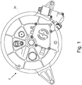
Figure 1 is a top view of a system in accordance with a first embodiment of the present invention, -
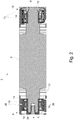
Figure 2 is a partial cross-sectional view of the system ofFigure 1 ; -
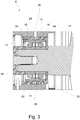
Figure 3 is a partial cross-sectional view showing the first bearing arrangement of the system ofFigure 1 ; -
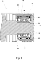
Figure 4 is a partial cross-sectional view showing the second bearing arrangement of the system ofFigure 1 ; -
Figure 5 is a partial cross-sectional view showing a bearing arrangement in accordance with a alternative embodiment of the present invention;
and -
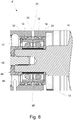
Figure 6 is a partial cross-sectional view showing a bearing arrangement in accordance with a further alternative embodiment of the present invention. - Referring to
Figure 2 , thesystem 2 according one embodiment of the present invention comprises aflywheel 4, ashaft 6, andbearing arrangements flywheel 4, i.e. the first bearingarrangement 8 is located on one axial side of the flywheel, and the second bearingarrangement 10 is located on the other side of theflywheel 4 with respect to the axis of the shaft. Each of thebearing arrangements bearings 12 mounted in arace 36 which is fixed rigidly to theshaft 6. An outer diameter of thebearing race 34 is held in abearing collar 14. Thebearing collar 14 is isolated from theflywheel housing 30 by an elastomeric component comprising a first pair of stiffelastomeric rings rings annular channels bearing collar 14. Thus therings bearings 12 with respect to theshaft 6. - The stiffness of the
rings system 2, the rings act to dampen any radial movement of theflywheel shaft 6, thus ensuring that the axis 'A' of theflywheel 4 does not move by more than a few microns. This ensures that a mechanical gear drive (not shown), which is connected to an end of theflywheel shaft 6, is maintained sufficiently close to its true centreline, thus ensuring correct operation of the gear drive and no contact between the periphery of theflywheel 4 and itshousing 30. - The situation of the
bearings 12 andelastomeric rings flywheel 4 ensures that interaction of the resonant modes of theflywheel 4 and thehousing 30 is prevented. - One of the bearing arrangements, 8, is restrained in both radial and axial directions with respect to the
shaft 6. Axial restraint is provided by a further elastomeric component comprising a second set of elastomeric rings, comprising a pair ofelastomeric rings 20, 22 (as illustrated in the right hand side bearingarrangement 8 ofFigure 2 , and in detail inFigure 4 ). - When the
flywheel system 2 is in operation, the elastomeric components provide damping, thereby preventing NVH, and also preventing interaction of resonant modes of the flywheel and of the housing. - An oil transmission passage is provided by a
channel 24 in the housing, andchannels bearing collar 14, to allow a controlled feed of oil (not shown) for lubrication of the bearings. The size of the oil transmission passage, (i.e. the size of thechannels - Although in the above embodiment, the
elastomeric rings - The
elastomeric rings bearings 12 with respect to theshaft 6, i.e. between thebearings 12 and theshaft 6. - In a system according to an alternative embodiment of the present invention, as illustrated in
Figure 5 , the bearing arrangements, one of which(8') is shown inFigure 5 , are mounted to theshaft 6 via a metalastic bush which comprises twoconcentric steel collars moulded rubber collar 46. In the embodiment ofFigure 5 , the metalastic bush 40 is located between the bearings arrangement 8', 10' and the shaft 6'. However, the bush 40 may alternatively be located between thebearings 12 and the flywheel housing 30. - A further alternative embodiment, as illustrated in
Figure 6 , may comprise abearing arrangement 8" comprising a metalastic bush 40 in combination with a first set ofelastomeric rings elastomeric rings Figure 6 , theelastomeric rings bearings 12 and thehousing 30, and the bush 40 is located between thebearings 12 and theshaft 6. However, the locations of the bush 40 and theelastomeric rings - In the present embodiment, restraint of the
bearing collar 14 is provided by a second pair ofelastomeric rings bearing collar 14 may be produced by moulding an elastomeric element and metal inner and outer rings as a single finished part. This alternative embodiment would be more suitable for mass production. - In further alternative embodiments, the first and/or second set of elastomeric rings may comprise a different number of rings.
Claims (15)
- A high speed flywheel system (2) comprising:a flywheel (4) mounted on a shaft (6);a housing, the shaft (6) being mounted on the housing;a first primary bearing arrangement (8) between the shaft (6) and the housing on a first side of the flywheel (4); anda second primary bearing arrangement (10) between the shaft (6) and the housing on a second side of the flywheel (4);characterised in thatthe first and second primary bearing arrangements (8, 10) each have an associated first elastomeric component arranged to provide radial restraint, and only the first primary bearing arrangement (8) has an associated second elastomeric component arranged to provide axial restraint,the system (2) further comprising an oil transmission passage (24, 26, 28) comprising a channel in the housing whereby oil can be fed to the bearings via the oil transmission passage.
- A high speed flywheel system (2) as claimed in claim 1 wherein each primary bearing arrangement (8, 10) comprises bearings (12) mounted in a race.
- A high speed flywheel system (2) as claimed in claim 2, wherein each race (14) is fixed to the shaft (6).
- A high speed flywheel system (2) as claimed in any preceding claim, wherein at least one of the first elastomeric components comprises a ring.
- A high speed flywheel system (2) as claimed in claim 4, wherein the ring is located radially outwardly of the corresponding primary bearing arrangement, between the corresponding primary bearing arrangement and the housing.
- A high speed flywheel system (2) as claimed in claim 4, wherein the ring is located radially inwardly of the corresponding primary bearing arrangement, between the corresponding primary bearing arrangement and the shaft (6).
- A high speed flywheel system (2) as claimed in claim 4 or claim 5 wherein the system (2) further comprises a bearing collar (14) and wherein the ring is contained within annular channels (32, 34) provided in the bearing collar (14).
- A high speed flywheel system (2) as claimed in any preceding claim further comprising a bush (40) comprising two concentric metal collars (42, 44), wherein one of the first elastomeric components comprises a rubber collar (46) located between the metal collars (42, 44).
- A high speed flywheel system (2) as claimed in claim 8 wherein the bush (40) is located radially outwardly of the corresponding primary bearing arrangement, between the corresponding primary bearing arrangement and the housing.
- A high speed flywheel system (2) as claimed in claim 8, wherein the bush (40) is located radially inwardly of the corresponding primary bearing arrangement, between the corresponding primary bearing arrangement and the shaft (6).
- A high speed flywheel system (2) as claimed in claim 5 and claim 10.
- A high speed flywheel system (2) as claimed in claim 6 and claim 9.
- A high speed flywheel system (2) as claimed in any one of the preceding claims, wherein the first elastomeric component and the second elastomeric component are separate components.
- A high speed flywheel system (2) as claimed in any one of the preceding claims wherein the second elastomeric component comprises a ring.
- A high speed flywheel system (2) as claimed in any one of the preceding claims wherein one or more of the elastomeric components are formed of a fluorocarbon material or natural rubber.
Applications Claiming Priority (2)
| Application Number | Priority Date | Filing Date | Title |
|---|---|---|---|
| GB1104406.2A GB2489021B (en) | 2011-03-16 | 2011-03-16 | High speed flywheel |
| PCT/GB2012/050448 WO2012123710A1 (en) | 2011-03-16 | 2012-02-28 | High speed flywheel |
Publications (2)
| Publication Number | Publication Date |
|---|---|
| EP2686577A1 EP2686577A1 (en) | 2014-01-22 |
| EP2686577B1 true EP2686577B1 (en) | 2021-05-19 |
Family
ID=43981049
Family Applications (1)
| Application Number | Title | Priority Date | Filing Date |
|---|---|---|---|
| EP12709686.5A Active EP2686577B1 (en) | 2011-03-16 | 2012-02-28 | High speed flywheel |
Country Status (7)
| Country | Link |
|---|---|
| US (1) | US9360082B2 (en) |
| EP (1) | EP2686577B1 (en) |
| JP (1) | JP6030076B2 (en) |
| KR (1) | KR20140045336A (en) |
| CN (1) | CN103443503B (en) |
| GB (1) | GB2489021B (en) |
| WO (1) | WO2012123710A1 (en) |
Families Citing this family (17)
| Publication number | Priority date | Publication date | Assignee | Title |
|---|---|---|---|---|
| GB2448930B (en) * | 2007-05-04 | 2009-08-19 | Flybrid Systems Llp | High speed flywheel seal |
| US20130199314A1 (en) * | 2012-01-26 | 2013-08-08 | Roller Bearing Company Of America, Inc. | Flywheel assembly for gyroscopic applications having ball bearing slug separators |
| JP2016508938A (en) | 2012-11-20 | 2016-03-24 | ウォルダーソン・マイアミ・エルエルシー | Method for generating gaseous fuel containing hydrogen from motion and / or potential energy recovered from a vehicle driven by a four-stroke diesel engine with an engine brake mechanism, and a system useful for performing such a method |
| JP6064783B2 (en) * | 2013-05-23 | 2017-01-25 | 日本精工株式会社 | Rolling bearing |
| FR3011880B1 (en) * | 2013-10-10 | 2015-10-23 | Snecma | DEVICE FOR TRANSFERRING OIL BETWEEN TWO REFERENTIALS IN ROTATION IN RELATION TO EACH OTHER, AND AIRCRAFT TURBOMACHINE FOR AIRCRAFT WITH SUCH A DEVICE |
| US9303689B2 (en) | 2014-04-29 | 2016-04-05 | Roller Bearing Company Of America, Inc. | Non-rhythmically spaced rolling elements for reduction in bearing non-repeatable run-out |
| GB2535182B (en) * | 2015-02-11 | 2019-09-04 | Punch Flybrid Ltd | Carrier |
| GB2535201B (en) * | 2015-02-12 | 2019-10-30 | Punch Flybrid Ltd | Link member for a flywheel |
| WO2016194198A1 (en) * | 2015-06-04 | 2016-12-08 | 三菱重工業株式会社 | Bearing device and supercharger |
| CN106763292B (en) * | 2016-12-31 | 2018-09-25 | 玉环现代汽车配件厂 | A kind of electromagnetic clutch |
| CN106870574B (en) * | 2017-03-31 | 2019-04-30 | 安徽江淮纳威司达柴油发动机有限公司 | A kind of guide bearing mounting base |
| GB2563617B (en) * | 2017-06-20 | 2020-04-08 | Dyson Technology Ltd | An electric machine |
| US10280974B2 (en) * | 2017-07-27 | 2019-05-07 | GM Global Technology Operations LLC | Structures and methods for controlled thermal expansion |
| JP7146353B2 (en) * | 2018-12-25 | 2022-10-04 | 東芝三菱電機産業システム株式会社 | bearing device |
| US10982730B2 (en) | 2019-03-04 | 2021-04-20 | Saint- Augustin Canada Electric Inc. | Flywheel systems and related methods |
| DE102019119224A1 (en) * | 2019-07-16 | 2021-01-21 | Dr. Ing. H.C. F. Porsche Aktiengesellschaft | Bearing cap |
| CN113483014B (en) * | 2021-06-23 | 2022-08-26 | 巴州大朴石油技术服务有限公司 | Instrument pulley for downhole operation |
Family Cites Families (29)
| Publication number | Priority date | Publication date | Assignee | Title |
|---|---|---|---|---|
| US2414335A (en) * | 1945-01-19 | 1947-01-14 | Jack & Heintz Prec Ind Inc | Ball-bearing assembly |
| US2439267A (en) * | 1945-02-23 | 1948-04-06 | Julius E Shafer | Resiliently mounted bearing |
| US2992868A (en) * | 1958-05-07 | 1961-07-18 | Vacha Fred | Mounting sleeve |
| JPS56153141A (en) * | 1980-04-26 | 1981-11-27 | Mitsubishi Electric Corp | Fly wheel device |
| JPS5720573A (en) * | 1980-07-10 | 1982-02-03 | Mitsubishi Electric Corp | Flywheel-type electric energy storage device |
| US4329000A (en) * | 1980-08-28 | 1982-05-11 | Caterpillar Tractor Co. | Self-contained, damped ball bearing assembly |
| JPS5837313A (en) * | 1981-08-28 | 1983-03-04 | Mitsubishi Heavy Ind Ltd | Bearing support mechanism of vertical high speed rotary member |
| JPS60141141A (en) * | 1983-12-28 | 1985-07-26 | Mitsubishi Electric Corp | Flywheel power source |
| US5253985A (en) * | 1990-07-04 | 1993-10-19 | Mtu Motoren- Und Turbinen-Union Friedrichshafen Gmbh | Exhaust gas turbocharger having rotor runners disposed in roller bearings |
| SE9503808L (en) * | 1995-10-30 | 1996-10-28 | Skf Ab | Car coupler unit |
| JP2000130502A (en) * | 1998-10-23 | 2000-05-12 | Chubu Electric Power Co Inc | Superconductive flywheel device |
| US6630761B1 (en) * | 2000-08-10 | 2003-10-07 | Christopher W. Gabrys | Combination mechanical and magnetic support for a flywheel power supply |
| JP3536022B2 (en) * | 2000-10-04 | 2004-06-07 | ミネベア株式会社 | Pivot bearing device |
| DE10195939D2 (en) * | 2001-02-01 | 2004-01-15 | Luk Lamellen & Kupplungsbau | bearing arrangement |
| FR2839396A1 (en) * | 2002-05-06 | 2003-11-07 | Technofan | Electric motor with improved support for shaft, uses a packing ring made of an elastic material between bearing and bearing housing to avoid vibration and compensate misalignment |
| KR20050084203A (en) * | 2002-12-09 | 2005-08-26 | 닛뽄 세이꼬 가부시기가이샤 | Electric power steering device |
| US7240583B2 (en) * | 2003-10-28 | 2007-07-10 | Honeywell International, Inc. | Dual function, highly damped, structurally and thermally compliant auxiliary bearing assembly |
| JP2006038209A (en) * | 2004-06-23 | 2006-02-09 | Mitsubishi Precision Co Ltd | Flywheel, control moment gyro and slide damping mechanism |
| JP2006242292A (en) * | 2005-03-03 | 2006-09-14 | Nsk Ltd | Bearing device |
| JP2007100901A (en) * | 2005-10-06 | 2007-04-19 | Mitsubishi Precision Co Ltd | Flywheel, control moment gyroscope, and damping mechanism |
| EP1970580B1 (en) * | 2005-12-27 | 2012-11-14 | Mitsubishi Heavy Industries, Ltd. | Planetary roller reduction gear |
| JP2008202782A (en) * | 2007-01-26 | 2008-09-04 | Jtekt Corp | Rolling bearing device |
| JP2008213074A (en) * | 2007-03-02 | 2008-09-18 | Disco Abrasive Syst Ltd | Driving mechanism and cutting device |
| DE102007037792A1 (en) * | 2007-08-10 | 2009-02-12 | Oerlikon Leybold Vacuum Gmbh | Pump bearing assembly |
| US8807840B2 (en) * | 2009-04-20 | 2014-08-19 | Borgwarner Inc. | Insulating and damping sleeve for a rolling element bearing cartridge |
| CN201434045Y (en) * | 2009-05-12 | 2010-03-31 | 青岛海之冠汽车配件制造有限公司 | Shock absorption type automobile flywheel |
| US8408806B2 (en) * | 2009-10-09 | 2013-04-02 | Dresser-Rand Company | Auxiliary bearing system with oil ring for magnetically supported rotor system |
| CA2686843A1 (en) * | 2009-12-02 | 2011-06-02 | Flywheel Energy Systems Inc. | Compliant bearing mount with a position restoring shear force absorber |
| CN103171615B (en) * | 2011-12-26 | 2016-12-28 | 株式会社捷太格特 | Driven steering device |
-
2011
- 2011-03-16 GB GB1104406.2A patent/GB2489021B/en active Active
-
2012
- 2012-02-28 WO PCT/GB2012/050448 patent/WO2012123710A1/en active Application Filing
- 2012-02-28 KR KR1020137023480A patent/KR20140045336A/en not_active Application Discontinuation
- 2012-02-28 JP JP2013558498A patent/JP6030076B2/en active Active
- 2012-02-28 US US14/001,009 patent/US9360082B2/en active Active
- 2012-02-28 EP EP12709686.5A patent/EP2686577B1/en active Active
- 2012-02-28 CN CN201280013614.2A patent/CN103443503B/en active Active
Non-Patent Citations (1)
| Title |
|---|
| None * |
Also Published As
| Publication number | Publication date |
|---|---|
| GB2489021A (en) | 2012-09-19 |
| KR20140045336A (en) | 2014-04-16 |
| EP2686577A1 (en) | 2014-01-22 |
| CN103443503B (en) | 2016-03-02 |
| JP6030076B2 (en) | 2016-11-24 |
| US9360082B2 (en) | 2016-06-07 |
| JP2014510885A (en) | 2014-05-01 |
| CN103443503A (en) | 2013-12-11 |
| US20140033859A1 (en) | 2014-02-06 |
| GB2489021B (en) | 2013-08-14 |
| WO2012123710A1 (en) | 2012-09-20 |
| GB201104406D0 (en) | 2011-04-27 |
Similar Documents
| Publication | Publication Date | Title |
|---|---|---|
| EP2686577B1 (en) | High speed flywheel | |
| US8956048B2 (en) | Squeeze film damper | |
| CN102016325B (en) | Bearing device for supercharger | |
| US8636413B2 (en) | Rotary bearing arrangement | |
| US8523726B2 (en) | Hybrid drive for a motor vehicle | |
| WO2016194198A1 (en) | Bearing device and supercharger | |
| JP2019203506A (en) | Single-row ball bearing with integrated squeeze-film damper | |
| KR20110101235A (en) | Double damping flywheel with double damping means, notably for a motor vehicle | |
| CN102216631B (en) | Turbocharger with a bearing arrangement for mounting a rotor shaft | |
| US9309922B2 (en) | Set of rolling bearings and corresponding rotary machine | |
| CN113439152B (en) | Device for centering and rotationally guiding a turbine shaft comprising a plurality of optimized damping fluid films | |
| US5816712A (en) | Elastomeric cartridges for attenuation of bearing-generated vibration in electric motors | |
| GB2522324A (en) | Bearing cage with a peripheral vibration damping ring | |
| US20230375037A1 (en) | Moving element damper | |
| JP2012177469A (en) | Torsional damper | |
| JP2017127150A (en) | Fixing structure of stator in motor | |
| CN102927196A (en) | Extrusion oil film damper running synchronously with propulsion shaft system | |
| US20210190139A1 (en) | Axial Damper And Displacement Limit For Turbomachine With Rolling Element Bearings | |
| WO2007002903A1 (en) | Vibration damping device for bearings and method of dampening vibrations | |
| JP2011515639A (en) | Noise-blocking rolling element bearing for crankshaft | |
| JP2007228689A (en) | Driving method of ac generator for vehicle | |
| US11746851B2 (en) | Damper arrangement and transmission for a motor vehicle drive train | |
| CN105626672A (en) | Crankshaft | |
| US9359899B2 (en) | Drive shaft system | |
| JP2014095419A (en) | Pulley with damper |
Legal Events
| Date | Code | Title | Description |
|---|---|---|---|
| PUAI | Public reference made under article 153(3) epc to a published international application that has entered the european phase |
Free format text: ORIGINAL CODE: 0009012 |
|
| 17P | Request for examination filed |
Effective date: 20130822 |
|
| AK | Designated contracting states |
Kind code of ref document: A1 Designated state(s): AL AT BE BG CH CY CZ DE DK EE ES FI FR GB GR HR HU IE IS IT LI LT LU LV MC MK MT NL NO PL PT RO RS SE SI SK SM TR |
|
| DAX | Request for extension of the european patent (deleted) | ||
| STAA | Information on the status of an ep patent application or granted ep patent |
Free format text: STATUS: EXAMINATION IS IN PROGRESS |
|
| 17Q | First examination report despatched |
Effective date: 20161201 |
|
| 19U | Interruption of proceedings before grant |
Effective date: 20171212 |
|
| 19W | Proceedings resumed before grant after interruption of proceedings |
Effective date: 20190301 |
|
| RAP1 | Party data changed (applicant data changed or rights of an application transferred) |
Owner name: PUNCH FLYBRID LIMITED |
|
| GRAP | Despatch of communication of intention to grant a patent |
Free format text: ORIGINAL CODE: EPIDOSNIGR1 |
|
| STAA | Information on the status of an ep patent application or granted ep patent |
Free format text: STATUS: GRANT OF PATENT IS INTENDED |
|
| INTG | Intention to grant announced |
Effective date: 20201222 |
|
| GRAS | Grant fee paid |
Free format text: ORIGINAL CODE: EPIDOSNIGR3 |
|
| GRAA | (expected) grant |
Free format text: ORIGINAL CODE: 0009210 |
|
| STAA | Information on the status of an ep patent application or granted ep patent |
Free format text: STATUS: THE PATENT HAS BEEN GRANTED |
|
| AK | Designated contracting states |
Kind code of ref document: B1 Designated state(s): AL AT BE BG CH CY CZ DE DK EE ES FI FR GB GR HR HU IE IS IT LI LT LU LV MC MK MT NL NO PL PT RO RS SE SI SK SM TR |
|
| REG | Reference to a national code |
Ref country code: GB Ref legal event code: FG4D |
|
| REG | Reference to a national code |
Ref country code: CH Ref legal event code: EP |
|
| REG | Reference to a national code |
Ref country code: DE Ref legal event code: R096 Ref document number: 602012075598 Country of ref document: DE |
|
| REG | Reference to a national code |
Ref country code: AT Ref legal event code: REF Ref document number: 1394270 Country of ref document: AT Kind code of ref document: T Effective date: 20210615 |
|
| REG | Reference to a national code |
Ref country code: IE Ref legal event code: FG4D |
|
| REG | Reference to a national code |
Ref country code: LT Ref legal event code: MG9D |
|
| REG | Reference to a national code |
Ref country code: AT Ref legal event code: MK05 Ref document number: 1394270 Country of ref document: AT Kind code of ref document: T Effective date: 20210519 |
|
| REG | Reference to a national code |
Ref country code: NL Ref legal event code: MP Effective date: 20210519 |
|
| PG25 | Lapsed in a contracting state [announced via postgrant information from national office to epo] |
Ref country code: AT Free format text: LAPSE BECAUSE OF FAILURE TO SUBMIT A TRANSLATION OF THE DESCRIPTION OR TO PAY THE FEE WITHIN THE PRESCRIBED TIME-LIMIT Effective date: 20210519 Ref country code: BG Free format text: LAPSE BECAUSE OF FAILURE TO SUBMIT A TRANSLATION OF THE DESCRIPTION OR TO PAY THE FEE WITHIN THE PRESCRIBED TIME-LIMIT Effective date: 20210819 Ref country code: HR Free format text: LAPSE BECAUSE OF FAILURE TO SUBMIT A TRANSLATION OF THE DESCRIPTION OR TO PAY THE FEE WITHIN THE PRESCRIBED TIME-LIMIT Effective date: 20210519 Ref country code: FI Free format text: LAPSE BECAUSE OF FAILURE TO SUBMIT A TRANSLATION OF THE DESCRIPTION OR TO PAY THE FEE WITHIN THE PRESCRIBED TIME-LIMIT Effective date: 20210519 Ref country code: LT Free format text: LAPSE BECAUSE OF FAILURE TO SUBMIT A TRANSLATION OF THE DESCRIPTION OR TO PAY THE FEE WITHIN THE PRESCRIBED TIME-LIMIT Effective date: 20210519 |
|
| PG25 | Lapsed in a contracting state [announced via postgrant information from national office to epo] |
Ref country code: LV Free format text: LAPSE BECAUSE OF FAILURE TO SUBMIT A TRANSLATION OF THE DESCRIPTION OR TO PAY THE FEE WITHIN THE PRESCRIBED TIME-LIMIT Effective date: 20210519 Ref country code: GR Free format text: LAPSE BECAUSE OF FAILURE TO SUBMIT A TRANSLATION OF THE DESCRIPTION OR TO PAY THE FEE WITHIN THE PRESCRIBED TIME-LIMIT Effective date: 20210820 Ref country code: IS Free format text: LAPSE BECAUSE OF FAILURE TO SUBMIT A TRANSLATION OF THE DESCRIPTION OR TO PAY THE FEE WITHIN THE PRESCRIBED TIME-LIMIT Effective date: 20210919 Ref country code: SE Free format text: LAPSE BECAUSE OF FAILURE TO SUBMIT A TRANSLATION OF THE DESCRIPTION OR TO PAY THE FEE WITHIN THE PRESCRIBED TIME-LIMIT Effective date: 20210519 Ref country code: RS Free format text: LAPSE BECAUSE OF FAILURE TO SUBMIT A TRANSLATION OF THE DESCRIPTION OR TO PAY THE FEE WITHIN THE PRESCRIBED TIME-LIMIT Effective date: 20210519 Ref country code: PL Free format text: LAPSE BECAUSE OF FAILURE TO SUBMIT A TRANSLATION OF THE DESCRIPTION OR TO PAY THE FEE WITHIN THE PRESCRIBED TIME-LIMIT Effective date: 20210519 Ref country code: PT Free format text: LAPSE BECAUSE OF FAILURE TO SUBMIT A TRANSLATION OF THE DESCRIPTION OR TO PAY THE FEE WITHIN THE PRESCRIBED TIME-LIMIT Effective date: 20210920 Ref country code: NO Free format text: LAPSE BECAUSE OF FAILURE TO SUBMIT A TRANSLATION OF THE DESCRIPTION OR TO PAY THE FEE WITHIN THE PRESCRIBED TIME-LIMIT Effective date: 20210819 Ref country code: ES Free format text: LAPSE BECAUSE OF FAILURE TO SUBMIT A TRANSLATION OF THE DESCRIPTION OR TO PAY THE FEE WITHIN THE PRESCRIBED TIME-LIMIT Effective date: 20210519 |
|
| PG25 | Lapsed in a contracting state [announced via postgrant information from national office to epo] |
Ref country code: NL Free format text: LAPSE BECAUSE OF FAILURE TO SUBMIT A TRANSLATION OF THE DESCRIPTION OR TO PAY THE FEE WITHIN THE PRESCRIBED TIME-LIMIT Effective date: 20210519 |
|
| PG25 | Lapsed in a contracting state [announced via postgrant information from national office to epo] |
Ref country code: DK Free format text: LAPSE BECAUSE OF FAILURE TO SUBMIT A TRANSLATION OF THE DESCRIPTION OR TO PAY THE FEE WITHIN THE PRESCRIBED TIME-LIMIT Effective date: 20210519 Ref country code: EE Free format text: LAPSE BECAUSE OF FAILURE TO SUBMIT A TRANSLATION OF THE DESCRIPTION OR TO PAY THE FEE WITHIN THE PRESCRIBED TIME-LIMIT Effective date: 20210519 Ref country code: CZ Free format text: LAPSE BECAUSE OF FAILURE TO SUBMIT A TRANSLATION OF THE DESCRIPTION OR TO PAY THE FEE WITHIN THE PRESCRIBED TIME-LIMIT Effective date: 20210519 Ref country code: SK Free format text: LAPSE BECAUSE OF FAILURE TO SUBMIT A TRANSLATION OF THE DESCRIPTION OR TO PAY THE FEE WITHIN THE PRESCRIBED TIME-LIMIT Effective date: 20210519 Ref country code: SM Free format text: LAPSE BECAUSE OF FAILURE TO SUBMIT A TRANSLATION OF THE DESCRIPTION OR TO PAY THE FEE WITHIN THE PRESCRIBED TIME-LIMIT Effective date: 20210519 Ref country code: RO Free format text: LAPSE BECAUSE OF FAILURE TO SUBMIT A TRANSLATION OF THE DESCRIPTION OR TO PAY THE FEE WITHIN THE PRESCRIBED TIME-LIMIT Effective date: 20210519 |
|
| REG | Reference to a national code |
Ref country code: DE Ref legal event code: R097 Ref document number: 602012075598 Country of ref document: DE |
|
| PLBE | No opposition filed within time limit |
Free format text: ORIGINAL CODE: 0009261 |
|
| STAA | Information on the status of an ep patent application or granted ep patent |
Free format text: STATUS: NO OPPOSITION FILED WITHIN TIME LIMIT |
|
| 26N | No opposition filed |
Effective date: 20220222 |
|
| PG25 | Lapsed in a contracting state [announced via postgrant information from national office to epo] |
Ref country code: IS Free format text: LAPSE BECAUSE OF FAILURE TO SUBMIT A TRANSLATION OF THE DESCRIPTION OR TO PAY THE FEE WITHIN THE PRESCRIBED TIME-LIMIT Effective date: 20210919 Ref country code: AL Free format text: LAPSE BECAUSE OF FAILURE TO SUBMIT A TRANSLATION OF THE DESCRIPTION OR TO PAY THE FEE WITHIN THE PRESCRIBED TIME-LIMIT Effective date: 20210519 |
|
| PG25 | Lapsed in a contracting state [announced via postgrant information from national office to epo] |
Ref country code: MC Free format text: LAPSE BECAUSE OF FAILURE TO SUBMIT A TRANSLATION OF THE DESCRIPTION OR TO PAY THE FEE WITHIN THE PRESCRIBED TIME-LIMIT Effective date: 20210519 |
|
| REG | Reference to a national code |
Ref country code: CH Ref legal event code: PL |
|
| REG | Reference to a national code |
Ref country code: BE Ref legal event code: MM Effective date: 20220228 |
|
| PG25 | Lapsed in a contracting state [announced via postgrant information from national office to epo] |
Ref country code: LU Free format text: LAPSE BECAUSE OF NON-PAYMENT OF DUE FEES Effective date: 20220228 |
|
| PG25 | Lapsed in a contracting state [announced via postgrant information from national office to epo] |
Ref country code: LI Free format text: LAPSE BECAUSE OF NON-PAYMENT OF DUE FEES Effective date: 20220228 Ref country code: IE Free format text: LAPSE BECAUSE OF NON-PAYMENT OF DUE FEES Effective date: 20220228 Ref country code: CH Free format text: LAPSE BECAUSE OF NON-PAYMENT OF DUE FEES Effective date: 20220228 |
|
| PG25 | Lapsed in a contracting state [announced via postgrant information from national office to epo] |
Ref country code: BE Free format text: LAPSE BECAUSE OF NON-PAYMENT OF DUE FEES Effective date: 20220228 |
|
| PGFP | Annual fee paid to national office [announced via postgrant information from national office to epo] |
Ref country code: FR Payment date: 20230213 Year of fee payment: 12 |
|
| PGFP | Annual fee paid to national office [announced via postgrant information from national office to epo] |
Ref country code: IT Payment date: 20230217 Year of fee payment: 12 Ref country code: GB Payment date: 20230117 Year of fee payment: 12 Ref country code: DE Payment date: 20230214 Year of fee payment: 12 |
|
| PG25 | Lapsed in a contracting state [announced via postgrant information from national office to epo] |
Ref country code: HU Free format text: LAPSE BECAUSE OF FAILURE TO SUBMIT A TRANSLATION OF THE DESCRIPTION OR TO PAY THE FEE WITHIN THE PRESCRIBED TIME-LIMIT; INVALID AB INITIO Effective date: 20120228 |