EP2686519B1 - Elektrische und statische klüftung einer lagerstätte - Google Patents
Elektrische und statische klüftung einer lagerstätte Download PDFInfo
- Publication number
- EP2686519B1 EP2686519B1 EP12708047.1A EP12708047A EP2686519B1 EP 2686519 B1 EP2686519 B1 EP 2686519B1 EP 12708047 A EP12708047 A EP 12708047A EP 2686519 B1 EP2686519 B1 EP 2686519B1
- Authority
- EP
- European Patent Office
- Prior art keywords
- fracturing
- reservoir
- electrodes
- arcs
- electrical
- Prior art date
- Legal status (The legal status is an assumption and is not a legal conclusion. Google has not performed a legal analysis and makes no representation as to the accuracy of the status listed.)
- Active
Links
- 230000003068 static effect Effects 0.000 title claims description 31
- 238000000034 method Methods 0.000 claims description 65
- 238000010891 electric arc Methods 0.000 claims description 37
- 230000008569 process Effects 0.000 claims description 31
- 229930195733 hydrocarbon Natural products 0.000 claims description 28
- 150000002430 hydrocarbons Chemical class 0.000 claims description 28
- 239000012530 fluid Substances 0.000 claims description 26
- 239000003990 capacitor Substances 0.000 claims description 24
- 239000004215 Carbon black (E152) Substances 0.000 claims description 18
- 230000035699 permeability Effects 0.000 claims description 12
- 239000000463 material Substances 0.000 claims description 10
- 229910000859 α-Fe Inorganic materials 0.000 claims description 6
- 238000010438 heat treatment Methods 0.000 claims description 4
- 230000001939 inductive effect Effects 0.000 claims description 3
- 230000003247 decreasing effect Effects 0.000 claims description 2
- 238000007789 sealing Methods 0.000 claims 1
- 239000007789 gas Substances 0.000 description 19
- 230000015556 catabolic process Effects 0.000 description 17
- 206010017076 Fracture Diseases 0.000 description 16
- 239000012071 phase Substances 0.000 description 15
- 238000004519 manufacturing process Methods 0.000 description 13
- XLYOFNOQVPJJNP-UHFFFAOYSA-N water Substances O XLYOFNOQVPJJNP-UHFFFAOYSA-N 0.000 description 13
- 238000002347 injection Methods 0.000 description 10
- 239000007924 injection Substances 0.000 description 10
- 239000000654 additive Substances 0.000 description 6
- 230000000996 additive effect Effects 0.000 description 6
- 230000035939 shock Effects 0.000 description 5
- 239000003795 chemical substances by application Substances 0.000 description 4
- 238000002474 experimental method Methods 0.000 description 4
- 239000007788 liquid Substances 0.000 description 4
- 239000011435 rock Substances 0.000 description 4
- 238000001228 spectrum Methods 0.000 description 4
- 230000005684 electric field Effects 0.000 description 3
- 239000012528 membrane Substances 0.000 description 3
- 239000000126 substance Substances 0.000 description 3
- 230000008901 benefit Effects 0.000 description 2
- 230000008878 coupling Effects 0.000 description 2
- 238000010168 coupling process Methods 0.000 description 2
- 238000005859 coupling reaction Methods 0.000 description 2
- 238000011161 development Methods 0.000 description 2
- 230000018109 developmental process Effects 0.000 description 2
- 238000010586 diagram Methods 0.000 description 2
- 238000005553 drilling Methods 0.000 description 2
- 230000000694 effects Effects 0.000 description 2
- 210000001061 forehead Anatomy 0.000 description 2
- 238000005259 measurement Methods 0.000 description 2
- 238000012856 packing Methods 0.000 description 2
- 229920006395 saturated elastomer Polymers 0.000 description 2
- 238000003860 storage Methods 0.000 description 2
- 241000923606 Schistes Species 0.000 description 1
- 208000027418 Wounds and injury Diseases 0.000 description 1
- 240000008042 Zea mays Species 0.000 description 1
- 238000009825 accumulation Methods 0.000 description 1
- 230000015572 biosynthetic process Effects 0.000 description 1
- 238000009530 blood pressure measurement Methods 0.000 description 1
- 244000309464 bull Species 0.000 description 1
- 238000004364 calculation method Methods 0.000 description 1
- 239000000919 ceramic Substances 0.000 description 1
- 238000007596 consolidation process Methods 0.000 description 1
- 230000001419 dependent effect Effects 0.000 description 1
- 239000003792 electrolyte Substances 0.000 description 1
- 230000003628 erosive effect Effects 0.000 description 1
- 238000011156 evaluation Methods 0.000 description 1
- 238000004880 explosion Methods 0.000 description 1
- 239000003302 ferromagnetic material Substances 0.000 description 1
- 238000002955 isolation Methods 0.000 description 1
- 230000002045 lasting effect Effects 0.000 description 1
- 238000012417 linear regression Methods 0.000 description 1
- 239000007791 liquid phase Substances 0.000 description 1
- 239000011325 microbead Substances 0.000 description 1
- 238000005065 mining Methods 0.000 description 1
- 238000005457 optimization Methods 0.000 description 1
- 230000000737 periodic effect Effects 0.000 description 1
- 239000011148 porous material Substances 0.000 description 1
- 230000000644 propagated effect Effects 0.000 description 1
- 239000003380 propellant Substances 0.000 description 1
- 238000011084 recovery Methods 0.000 description 1
- 238000004064 recycling Methods 0.000 description 1
- 230000002787 reinforcement Effects 0.000 description 1
- 230000004044 response Effects 0.000 description 1
- 239000004576 sand Substances 0.000 description 1
- 230000007480 spreading Effects 0.000 description 1
- 238000003892 spreading Methods 0.000 description 1
- 238000012360 testing method Methods 0.000 description 1
- 239000002562 thickening agent Substances 0.000 description 1
- 238000012549 training Methods 0.000 description 1
Images


Classifications
-
- E—FIXED CONSTRUCTIONS
- E21—EARTH OR ROCK DRILLING; MINING
- E21B—EARTH OR ROCK DRILLING; OBTAINING OIL, GAS, WATER, SOLUBLE OR MELTABLE MATERIALS OR A SLURRY OF MINERALS FROM WELLS
- E21B43/00—Methods or apparatus for obtaining oil, gas, water, soluble or meltable materials or a slurry of minerals from wells
- E21B43/25—Methods for stimulating production
- E21B43/26—Methods for stimulating production by forming crevices or fractures
-
- E—FIXED CONSTRUCTIONS
- E21—EARTH OR ROCK DRILLING; MINING
- E21B—EARTH OR ROCK DRILLING; OBTAINING OIL, GAS, WATER, SOLUBLE OR MELTABLE MATERIALS OR A SLURRY OF MINERALS FROM WELLS
- E21B36/00—Heating, cooling or insulating arrangements for boreholes or wells, e.g. for use in permafrost zones
- E21B36/04—Heating, cooling or insulating arrangements for boreholes or wells, e.g. for use in permafrost zones using electrical heaters
-
- E—FIXED CONSTRUCTIONS
- E21—EARTH OR ROCK DRILLING; MINING
- E21B—EARTH OR ROCK DRILLING; OBTAINING OIL, GAS, WATER, SOLUBLE OR MELTABLE MATERIALS OR A SLURRY OF MINERALS FROM WELLS
- E21B43/00—Methods or apparatus for obtaining oil, gas, water, soluble or meltable materials or a slurry of minerals from wells
- E21B43/003—Vibrating earth formations
Definitions
- the present invention relates to a device and a method for fracturing a geological reservoir of hydrocarbons, as well as a process for the production of hydrocarbons.
- the permeability and / or porosity of the material constituting the reservoir has an influence on the production of hydrocarbons, in particular on the speed of production and thus the profitability.
- This is particularly recalled by the article " Porosity and Permeability of Eastern Devonian Shale Gas "by Soeder, DJ, published in SPE Training Evaluation, 1988, vol 3, No. 1, pp. 116-124 , which presents the study of eight samples of "shale gas” (ie gas schist) of the Devonian, from the Appalachians.
- This article explains in particular that the production of this shale gas has the problem that the permeability of the reservoir (ie the material constituting the reservoir) is low.
- Static fracturing is a targeted dislocation of the reservoir, by means of the injection under very high pressure of a fluid intended to crack the rock.
- the crack is made by a mechanical "stress” resulting from a hydraulic pressure obtained using a fluid injected under high pressure from a well drilled from the surface.
- Hydrofracturing or “hydrosilicous fracturing” (or “frac jobs”, “frac'ing” or more generally “fracking”, or “massive hydraulic fracturing”).
- the document US 2009/044945 A1 particularly presents a static fracturing method as described above.
- Static fracturing has the disadvantage that tank fracturing is generally unidirectional. Thus, only the hydrocarbon present in the reservoir portion around a deep but very localized crack is produced more rapidly.
- Electric fracturing involves generating an electric arc in a well drilled in the reservoir (typically the production). The electric arc induces a pressure wave that damages the reservoir in all directions around the wave and thus increases its permeability.
- the document US 4,074,758 discloses a method of generating an electro-hydraulic shock wave in a liquid in the wellbore to better recover oil.
- the document US 4,164,978 suggests following the shock wave with an ultrasonic wave.
- the document US 5,106,164 also describes a method for generating a plasma explosion and thus fracturing a rock, but in the case of a shallow hole, for a mining application and not for the production of hydrocarbons.
- the documents US 4,651,311 and US 4,706,228 have a device for generating an electric discharge with electrodes in a chamber containing an electrolyte, wherein the electrodes are not subject to erosion by the plasma of the discharge.
- the document WO 2009/073475 discloses a method for generating an acoustic wave in a fluid medium present in a well with a device comprising two electrodes between an upper packer and a lower packer defining a confined space. This document describes that the acoustic wave is maintained in a non-"shock wave” state in order to improve the damage, without, however, clarifying the differences between "ordinary” acoustic wave and "shock” wave.
- the document US 4, 343, 356 discloses a fracturing method including static fracturing and electrical fracturing.
- the process of figure 1 includes static fracturing (S20) of the tank by hydraulic pressure. And the process of figure 1 also includes, before, during or after the static fracturing (S20) (these three possibilities being represented by the dashed lines on the figure 1 ), an electrical fracturing (S10) of the tank by generating an electric arc in a well drilled in the tank.
- S20 static fracturing
- S10 electrical fracturing
- the term "electric arc” refers to an electric current created in an insulating medium.
- the generation of the electric arc induces a "pressure wave", i.e. a mechanical wave passing through a pressure in the middle in which the wave passes.
- the generation of the electric arc allows more diffuse / multidirectional reservoir damage than the damage resulting from static fracturing.
- the generation of the electric arc thus causes microcracks in all directions around the position of the electric arc, and thus increases the permeability of the reservoir, typically by a factor of 10 to 1000.
- this increase in permeability intervenes without using a means to prevent the closing of microcracks, such as propellant injection.
- electrical fracturing (S10) does not require considerable energy or too much water. There is therefore no need for a particular water recycling system.
- the electric arc is preferably generated in a fluid present in a well drilled in the tank.
- the pressure wave resulting from the electric arc is thus transmitted with fewer attenuations.
- the drilled well contains fluid which is typically water.
- electric fracturing (S10) follows a drilling process, the drilled well can be automatically filled with water present in the tank. Potentially, if the drilled well does not fill automatically, it can be filled artificially.
- Static fracturing can be any type of static fracturing known from the prior art.
- the static fracturing (S20) may comprise, after the eventual drilling of a well in the reservoir, the injection of a fluid under high pressure into the well.
- Static fracturing (S20) thus creates one or more unidirectional cracks, typically deeper than those created by electrical fracturing (S10).
- the fluid can be water, a mud or a technical fluid with controlled viscosity enriched with hard agents (grains of sieved sand, or ceramic microbeads) which prevent the fracture network from closing on itself at the time of the pressure drop.
- hard agents grains of sieved sand, or ceramic microbeads
- Static fracturing may comprise a first injection phase in a well drilled with a fracturing fluid that contains thickeners, and a second phase that involves the periodic introduction of propant (ie a proppant) into the fracturing fluid to feed the fracture created by propelling.
- propant ie a proppant
- the second phase or its sub-phases involves the additional introduction of a reinforcement and / or consolidation material, thereby increasing the strength of the propant clusters formed in the fracturing fluid.
- Such static fracturing (S20) makes it possible to obtain fractures typically between 100 and 5000 meters.
- Static fracturing can precede electrical fracturing (S 10).
- the pressure wave generated by electrical fracturing can follow the course of the fluid introduced into the cracks created by static fracturing. (S20) and thus improve the damage.
- such an order between the fracturations (S20) and (S10) presents little risk of leakage.
- static fracturing (S20) can precede electrical fracturing (S10) by less than a week.
- the process of figure 2 includes the only electrical fracking (S10) of the tank, carried out in a reservoir where a well has already been drilled and has already been statically fractured.
- the process of figure 2 allows the damage of tanks already exploited after static fracturing.
- the process of figure 2 allows the exploitation of an abandoned reservoir because already exploited, potentially by reusing a well already drilled.
- the process of figure 2 corresponds to the process of figure 1 (where static fracturing (S20) corresponds to this preliminary static fracturing).
- the preliminary static fracturing may have been carried out according to the method of figure 1 .
- Electric fracturing (S10) proposed in the process of the figure 3 can of course be used in the process of the figure 1 and / or in the process of figure 2 .
- the process of figure 3 mainly involves the electrical fracturing (S10) of the reservoir by the generation of an electric arc in a fluid present in a well drilled in the reservoir (thus combined or not with a static fracturing, for example the static fracturing (S20) of the process of the figure 1 ).
- the electric arc induces a pressure wave whose rise time is greater than 0.1 ⁇ s, preferably greater than 10 ⁇ s.
- the process figure 3 improves the fracturing of the tank.
- the rise time of the pressure wave is the time required for the pressure wave to reach the pressure peak, ie the maximum value of the wave (also called “peak pressure").
- a rise time greater than 0.1 ⁇ s, preferably greater than 10 ⁇ s corresponds to a pressure wave which penetrates better into the tank.
- Such a pressure wave is particularly effective (ie the wave penetrates deeper) in the case of ductile materials, such as those that make up shale gas reservoirs.
- the rise time is less than 1 ms, advantageously less than 500 ⁇ s.
- the pressure wave may have a maximum pressure of up to 10 kbar, preferably greater than 100 bar and / or less than 1000 bar. This may correspond to an energy stored between 10 J and 2 MJ, preferably between 10 kJ and 500 kJ.
- the well can be horizontal.
- the well may be horizontal and have a length preferably between 500 and 5000 m, preferably between 800 and 1200 m, for example at a depth between 1000 and 10000 m, for example between 3000 and 5000 m.
- Electric fracturing (S10) can be repeated in different treatment zones along the well. Indeed, with electric fracturing (S10), there is a pressure wave that generally penetrates less deeply than static fracturing. Thus, with electrical fracturing (S10), cracks of length less than 100 m, typically less than 50 m, and typically greater than 20 m, are typically obtained. For a well several hundred meters long, the repetition of electrical fracturing (S10) along the well allows damage along the well and therefore a better possible exploitation of the reservoir.
- each treatment zone or in the single treatment zone if it is unique, several arcs can be generated afterwards.
- the generation of an electric arc is repeated in a substantially fixed position. This improves the damage by repeating the pressure wave.
- the generated arcs can be the same or different.
- the arcs subsequently generated induce a pressure wave whose rise time is decreasing.
- the arches in succession can present an increasingly steep front, thus inducing a pressure wave having a rise time faster and faster.
- the first impulses have slower fronts to penetrate deeply, whereas the pulses to the stiffer fronts fracture closer to the well and more densely. We optimize damage.
- the first arcs can for example induce a pressure wave whose rise time is greater than 10 ⁇ s, preferably 100 ⁇ s.
- the last arcs can then induce a pressure wave whose rise time is less than the rise time of the first arcs, for example less than 10 ⁇ s or 100 ⁇ s.
- the first arcs comprise at least one arc, preferably a number less than 10,000 or even 1000, and the last arcs comprise at least one arc, preferably a number less than 10,000 or even 1000.
- the arcs can be generated at a frequency less than 100 Hz, preferably less than 10 Hz, and / or greater than 0.001 Hz, preferably greater than 0.01 Hz.
- the frequency of the arcs can be (substantially) equal to the resonant frequency of the material to be fractured in the tank. This ensures more effective damage.
- the reservoir may have a permeability less than 10 microdarcy.
- This may include a shale gas tank.
- the gas is typically adsorbed (up to 85% on Lewis Shale) and poorly trapped in pores.
- the low permeability of this type of reservoir does not make it possible to hope to directly produce trapped gases in such a medium, only the surface gas (adsorbed gas) can be produced.
- an effective electrical fracturing (S10) over a radius of 30 m along a horizontal well of 1000 m would allow a recovery of gas that can exceed 50 MNm 3 (assuming 26 Nm 3 of gas per m 3 of rock as suggested by the article "Porosity and Permeability of Eastern Devonian Shale gas” above).
- the fracturing process of any of the Figures 1 to 3 can thus be included in a hydrocarbon production process of the tank, typically shale gas.
- Electric fracturing may comprise the prior injection into the fluid of an agent improving the plasticity of the material constituting the reservoir.
- the agent may comprise a chemical additive.
- the chemical additive may be an agent inducing the rock fracture.
- the additive may include steam. This helps to further improve the fracturing.
- electrical fracturing (S10) of the fracturing process of any of the Figures 1 to 3 will now be described with reference to figures 4 to 6 .
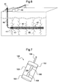
- electrical fracturing (S10) of a tank 40 is carried out in which a horizontal well 43 has been drilled.
- Electrical fracturing (S10) is here combined with static fracturing, not specifically illustrated and possibly prior, which has induced major fractures 41 in the reservoir.
- the fracturing process here makes it possible to produce hydrocarbon by means of a production pipe located at the surface, at the wellhead 45.
- the electric arc is here generated at the level of a fracturing device 47.
- electrical fracturing induces secondary fractures 42 at the point where the arc is generated.
- the secondary fractures 42 are shorter but more diffuse than the main fractures 41.
- the electrical fracturing (S10) is repeated in different treatment zones along the well.
- the figure 4 indeed shows an initial phase of electrical fracturing (S10) downhole.
- the figure 5 shows an intermediate phase in the middle of wells.
- the figure 6 shows a final phase at the beginning of the well.
- the progression of secondary fractures 42 is thus observed during the repetition of electrical fracturing.
- the secondary fractures 42 are dispersed all around the well 43. It is then possible to recover the hydrocarbon surrounding these secondary fractures 42, a hydrocarbon potentially distant from the main fractures 41 and thus difficult to recover by a single static fracturing.
- the electric arc of the process of any of the Figures 1 to 3 or 4 to 6 can be generated by any device provided for the generation of such an arc.
- a particular device for generating the arc will now be described. It is understood that the different functionalities of the particular device (ie the different actions that it makes it possible to perform) can be integrated into the process of any one of the Figures 1 to 3 , in particular to the electrical fracturing S10 of the process.
- the particular fracturing device of a hydrocarbon geological reservoir comprises two packings defining between them a confined space in a well drilled in the reservoir (ie intended to be confined at least when the particular device is installed in a drilled well in the tank), and an electrical circuit (configured / adapted / planned) for generating an electric arc between two electrodes arranged in the confined space.
- the circuit comprises at least one voltage source connected to the electrodes and an inductance between the voltage source and one of the two electrodes.
- the device also includes a pump for increasing the pressure of a fluid in the confined space and a fluid heater. The particular device improves the fracturing of the reservoir.
- the seals may be provided to conform to the well wall, generally cylindrical, thereby defining a confined space therebetween.
- the device may comprise a membrane that delimits the confined space.
- the membrane is then preferentially made of a material suitable for good conduction of pressure waves, which optimizes electrical fracturing (S10).
- confined is meant that the confined space is provided so that the pressure and temperature therein can be changed by the pump and the heater, as known to those skilled in the art. This optimizes the fluid present in the confined space to promote the appearance of an electric arc between the two electrodes, depending on the conditions of the reservoir or the nature of the fluid. For example, increasing the temperature at constant pressure generally facilitates the appearance of an electric arc.
- “containment” may but does not necessarily mean complete closure, and similarly, the seal may but is not necessarily total.
- the circuit comprises at least one inductor between the voltage source and the electrode to which it is connected.
- the inductance can be any component that induces a time delay of the current with respect to the voltage.
- the value of an inductance is expressed in Henry.
- the inductance may thus be a coil, possibly wound around a core of ferromagnetic material, or ferrites. Inductance is also known as "self”, “solenoid” when it comes to a coil, or “self-inductance”.
- the inductance attenuates the current front in the circuit. This makes it possible to obtain a rise time of the slower pressure wave, and thus a pressure wave which penetrates better into the tank. Damage to the tank is thus deeper.
- the inductance may be greater than 1 ⁇ H or 10 ⁇ H, and / or less than 100 mH or 1 mH.
- the device can be movable along the well and set before the generation of an electric arc.
- the device may comprise moving means, eg by remote control. This allows the device to be adapted in particular to the fracturing process of Figures 4 to 6 , with the benefits that flow from it.
- the device can then be powered by a high voltage power supply located on the surface and connected to the device by electrical cables following the well.
- a high voltage power supply located on the surface and connected to the device by electrical cables following the well.
- the mobility of the fracturing device 47 which may be the particular device, makes it possible to fracture the reservoir all along the well.
- the device 47 is fed in this example by a high voltage power supply 44 located on the surface and connected to the device 47 by the cables 46.
- the device can then also include a stall system. This allows the device to remain in the well when it is blocked. We can then recover the well and / or the stem train.
- the device may be of generally elongated shape, which allows it to be moved more easily in the well.
- the device may also include several pairs of electrodes, over a length.
- the electrodes can be powered by several storage capacities. This makes it possible to perform the fracturing more quickly. Indeed, several arcs can then be generated at the same time between each pair of electrodes, and achieve several damages at the same time.
- the device may include a chemical additive injection system that includes a storage tank for storing the additive and a pump for injecting the additive into the confined volume during use of the device.
- the heater may include a source of hot fluid and a delivery conduit, the conduit having an opening proximate the electrodes such that, during operation of the device, hot fluid may be delivered from the source to the electrodes so as to create a thermal gradient between the electrodes.
- the conduit can pass through one or both electrodes.
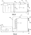
- the device 100 of the figure 7 comprises the two packings 102 and 103 defining between them the confined space 104.
- the confined space 104 is here delimited further by the membrane 108.
- the device 100 also comprises the two electrodes 106 arranged in the confined space 104
- the two electrodes 106 are respectively connected to the voltage source via an input 109 and to a ground 103 (here merged with the gasket 103) of the circuit, which allows the formation of the electric arc. between the two electrodes 106.
- the electrodes may have a radius of between 0.1 mm and 50 mm, preferably between 1 mm and 30 mm.
- the pump for increasing the pressure of a fluid in the confined space and the fluid heating apparatus are not shown.
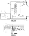
- the electric circuit for the generation of an electric arc between the two electrodes 106, its voltage source and the inductance are not represented either, but may be in accordance with Figures 8 to 10 which schematically show examples of the device 100.
- the device 100 of the figure 8 comprises the inductor 110.
- the voltage source comprises the capacitor 112.
- the capacitor 112 may have a capacitance greater than 1 ⁇ F, preferably greater than 10 ⁇ F. Such a capacity makes it possible to reach an energy causing the appearance of a subsonic arc.
- An electric arc is said to be “subsonic” or “supersonic” depending on its speed.
- a “subsonic” arc is typically associated with thermal processes: the arc is propagated through gas bubbles created by the heating of the water. We speak of “slow” propagation of the electric discharge, typically of the order of 10 m / s. The main characteristics of a subsonic discharge are related to high energies involved (typically beyond several hundred Joules), thermal processes associated with a long time of application of the voltage and at low levels of energy. voltage (low electric field). In this discharge regime, the pressure wave propagates in a large volume of gas before spreading in the fluid.
- a “supersonic” arc is typically associated with electronic processes.
- the discharge propagates in the water without a thermal process with a filamentary appearance.
- the characteristics of a supersonic discharge are related to low energies involved, to high voltages associated with a short application time and to strong electric fields (MV / cm).
- MV / cm strong electric fields
- the thermal effects are negligible. Since the discharge can not develop directly in the liquid phase, the notion of micro-bubbles can be taken into account to explain the development of this discharge regime.
- the volume of gas involved is lower than in the case of subsonic discharges.
- the capacitor 112 may have a capacity of less than 1000 ⁇ F, preferably less than 200 ⁇ F.
- the capacitor 112 is separated from the inductor by the spark gap 114 which can be initiated by the pulse generator 116. This makes it possible to control the discharges of the capacitor 112 and thus the pressure waves generated by the electric arc.
- the pulse generator 116 may be configured for a repetition of the waves as described above.
- the voltage source (i.e. the capacitor 112) is charged by a high voltage charger 120 provided in an auxiliary circuit 122 at a voltage U of between 1 and 500 kV, preferably between 50 and 200 kV.
- the auxiliary circuit is preferably located on the surface, and is then separable from the device.
- the device 100 of the figure 9 is different from the example of the figure 8 in that a Marx generator 118 replaces the capacitor 112 and the assembly (spark gap 114 + pulse generator 116).
- the generator Marx 118 allows during its discharge the creation of a supersonic electronic arc, imposing a higher voltage than the capacitor 112.
- the voltage source comprises the capacitor 112 of the figure 8 and the Marx generator 118 of the figure 9 .
- the pulse generator 116 primes the first spark gap 117 of the Marx generator 118.
- the device 100 further includes the ferrites 119 forming a saturable inductance in a path leading the capacitor directly to the inductor.
- the ferrites 119 are configured to be saturated once the Marx generator 118 is discharged. Once the ferrites 119 are saturated, only the capacitor 112 discharges. This allows a temporary isolation of the capacitor 112 and thus the passage (ie switching) of a supersonic arc to a subsonic arc.
- the device thus provides a coupling between a supersonic discharge and subsonic.
- the subsonic discharge produced by the capacitor 112 occurs after a delay corresponding to the breakdown time of the generator Marx 118.
- the switching can be done in a time less than 1 s.
- the duration of the discharge produced by the Marx generator 118 is very short, lasting less than 1 microsecond, and amplitude greater than 100 kV.
- the various components of the device 100 are of adjustable characteristics, ie their characteristics can be modified before use as a function of the reservoir, or during use depending on the response or the progress of the fracturing.
- the coil 110 may be of adjustable inductance.
- the characteristics of the Marx generator 118 (capacity of each capacitor in parallel, number of capacitors operating) can be adjustable.
- the distance between the electrodes 106 preferably between 0.2 and 5 cm, more preferably between 1 and 3 cm, can also be adjustable.
- the capacitance of the capacitor 112 can also be adjustable. This makes it possible to have a device 100 adapted to the fracturing of any type of tank. Indeed, it is not necessary to replace the device 100 when changing the reservoir to be fractured (and that the material is different) because it is sufficient to modify one or more of the adjustable parameters. This also makes it possible to optimize the damage by modifying, possibly remotely, the parameters in use.
- the generation of the pressure wave can be decomposed into two phases: a pre-discharge phase S100 and a post-discharge phase S110, separated by the S105 appearance of the bow.
- the voltage drops. This fall corresponds to the discharge of the equivalent capacity of the energy bank or the Marx generator into the equivalent resistance of the device 100.
- the equivalent resistance is important, the better is the conservation of energy in the pre-breakdown phase.
- the configuration of electrodes can therefore, in each case (subsonic or supersonic) allow to obtain the least possible loss of energy. This corresponds to the optimization of the water heating in one case and the electric field in the other.
- the electric circuit can be modeled by a RLC circuit in oscillating mode.
- This current i (t) is a function of the breakdown voltage U B (dielectric breakdown of the medium) of the capacitor, the inductance and the resistance of the circuit.
- a pressure sensor has been used to visualize the waveforms of the pressures generated as a function of the frequency spectrum.
- This frequency spectrum can indeed be modified by the dielectric breakdown mode, by the parameters of the electric circuit, by the volume of gas, as well as by the nature of the liquid used.
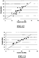
- Two examples of frequency spectrum associated with a subsonic and supersonic discharge were tested. It appeared that the lower frequencies the spectrum has, the less diffuse the damage.
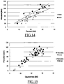
- the result of various experiments carried out shows a linear relation of the dP max / dt p as a function of the current front di max / dt i , represented on the figure 16 .
- the current front has an influence on the pressure front. The slower the current front, the lower the pressure.
- the peak current i max is controlled by the available energy at the moment of the arc noted E b and by the inductance of the circuit L, these are the two parameters on which the user must act.
- the resistance R is considered very weak and the capacitance C is a function of the energy E b .
- the peak pressure generated is therefore controlled by the current i max (parameters E b and L) and by the coefficient k 1 (function of the inter-electrode distance and the dielectric breakdown mode of the water). We can therefore act on E b , L and k 1 to obtain the desired pressure.
- the front of the pressure wave is thus controlled by the coefficients k 1 and k 2 and by the values of L and C (electrical circuit parameters).
- the geometry of the electrodes, with constant injected current, has no influence on the peak pressure generated, but may play a role in reducing the electrical losses in the pre-discharge phase.
- the above studies confirm the utility of introducing an inductance between the voltage source and one of the two electrodes to act on the pressure wave generated in the end.
- the studies also confirm the interest of having adjustable parameters, e.g. the inductance, the capacity of the capacitor, the characteristics of the generator of Marx. Indeed, the pressure wave depends on these parameters, the ability to adjust them to control the pressure wave.
- the present invention is not limited to the examples described and shown, but it is capable of numerous variants accessible to those skilled in the art.
- the principles outlined above can be applied to the production of seismic data.
- the generation of the electric arc could alternatively induce a pressure wave having characteristics lower than those required for the fracturing of the reservoir. This can be done, for example, by adapting the charging voltage of the fracturing device and the charging voltage, and by varying the inductance.
- Such a seismic data production method can then comprise the reception of a reflection of the pressure wave, the reflected wave then being typically modulated by its passage through the material constituting the reservoir.
- the seismic data generating method can then also include analyzing the reflected wave to determine reservoir characteristics. We can then build a seismic survey based on the reception.
Landscapes
- Geology (AREA)
- Life Sciences & Earth Sciences (AREA)
- Engineering & Computer Science (AREA)
- Mining & Mineral Resources (AREA)
- Environmental & Geological Engineering (AREA)
- Fluid Mechanics (AREA)
- Physics & Mathematics (AREA)
- General Life Sciences & Earth Sciences (AREA)
- Geochemistry & Mineralogy (AREA)
- Physical Or Chemical Processes And Apparatus (AREA)
- Supply Devices, Intensifiers, Converters, And Telemotors (AREA)
- Underground Structures, Protecting, Testing And Restoring Foundations (AREA)
- Geophysics And Detection Of Objects (AREA)
Claims (13)
- Verfahren zur Klüftung einer geologischen Kohlenwasserstofflagerstätte, wobei das Verfahren umfasst:- eine statische Klüftung (S20) der Lagerstätte durch hydraulischen Druck, und- eine elektrische Klüftung (S10) der Lagerstätte durch Erzeugung von Lichtbögen in einem in die Lagerstätte gebohrten Bohrloch;dadurch gekennzeichnet, dass die statische Klüftung (S20) der elektrischen Klüftung (S10) vorhergeht, und dass die elektrische Klüftung (S10) durch eine Klüftungsvorrichtung (100) erzeugt wird, umfassend:- zwei Dichtungen (102, 103), die zwischen sich einen eingegrenzten Raum (104) in einem in die Lagerstätte gebohrten Bohrloch definieren;- eine Pumpe zur Erhöhung des Drucks eines Fluids in dem eingegrenzten Raum;- ein Gerät zur Erhitzung des Fluids;- mindestens ein Paar von zwei Elektroden (106), die in dem eingegrenzten Raum (104) angeordnet sind; und- eine elektrische Schaltung für die Erzeugung der Lichtbögen zwischen den zwei Elektroden (106), wobei die Schaltung umfasst:wobei die Schaltung nacheinander den Überschall-Lichtbogen und den Unterschall-Lichtbogen erzeugt; und wobei die Klüftung eine Erzeugung mehrerer Lichtbögen hintereinander umfasst, wobei die Lichtbögen eine Druckwelle induzieren, deren Anstiegszeit abnehmend ist, und wobei die Lichtbögen hintereinander eine Druckwelle induzieren, deren Anstiegszeit unter 100 µs beträgt.* mindestens eine Spannungsquelle (112, 118), die mit den Elektroden (106) verbunden ist und einen Kondensator (112) umfasst;* eine Induktanzspule (110) zwischen der Spannungsquelle und einer der zwei Elektroden;* einen Marx-Generator (118), der sich zwischen dem Kondensator (112) und der Induktanzspule (110) befindet, um einen Überschall-Lichtbogen zwischen den Elektroden zu erzeugen; und* Ferrite (119), die eine sättigbare Induktanz und eine Funkenstrecke (114) bilden, wobei die Ferrite (119) und die Funkenstrecke (114) auf einem selben Schenkel der Schaltung angeordnet sind und sich parallel zum Marx-Generator (118) zwischen dem Kondensator (112) und der Induktanzspule (110) erstrecken, um einen Unterschall-Lichtbogen zwischen den zwei Elektroden (106) zu erzeugen,
- Verfahren nach Anspruch 1, bei dem das Bohrloch (43) horizontal ist.
- Verfahren nach Anspruch 1 oder 2, bei dem die elektrische Klüftung (S10) in verschiedenen Behandlungszonen entlang des Bohrlochs (43) weiderholt wird.
- Verfahren nach Anspruch 3, bei dem mehrere Lichtbögen hintereinander in jeder Behandlungszone erzeugt werden.
- Verfahren nach Anspruch 4, bei dem in jeder Behandlungszone die Lichtbögen mit einer Frequenz gleich der Resonanzfrequenz eines zu klüftenden Materials in der Lagerstätte erzeugt werden.
- Verfahren nach Anspruch 5, bei dem die Lichtbögen mit einer Frequenz unter 100 Hz, vorzugsweise unter 10 Hz, und/oder über 0,001 Hz, vorzugsweise über 0,01 Hz, erzeugt werden.
- Verfahren nach einem der vorhergehenden Ansprüche, bei dem die Lagerstätte (40) eine Durchlässigkeit unter 10 Mikrodarcy hat.
- Verfahren nach einem der vorhergehenden Ansprüche, bei dem die Lagerstätte (40) eine Schiefergaslagerstätte ist.
- Verfahren zur Klüftung einer geologischen Kohlenwasserstofflagerstätte, die vorher durch hydraulischen Druck statisch geklüftet wurde, wobei das Verfahren eine elektrische Klüftung (S10) der Lagerstätte nach einem der vorhergehenden Ansprüche umfasst.
- Verfahren nach Anspruch 1, bei dem die Induktanzspule von einstellbarer Induktanz ist, die vorzugsweise zwischen 1 µH und 100 mH, noch bevorzugter zwischen 10 µH und 1 mH, beträgt.
- Verfahren nach einem der vorhergehenden Ansprüche, bei dem ein Abstand zwischen den Elektroden einstellbar ist, vorzugsweise zwischen 0,2 und 5 cm, noch bevorzugter zwischen 1 und 3 cm, beträgt.
- Verfahren nach einem der vorhergehenden Ansprüche, bei dem die Spannungsquelle einen Kondensator (112) mit einstellbarer Kapazität umfasst.
- Verfahren zur Erzeugung von Kohlenwasserstoffen, umfassend die Klüftung einer geologischen Kohlenwasserstofflagerstätte gemäß dem Verfahren nach einem der vorhergehenden Ansprüche.
Applications Claiming Priority (2)
| Application Number | Priority Date | Filing Date | Title |
|---|---|---|---|
| FR1152063A FR2972757B1 (fr) | 2011-03-14 | 2011-03-14 | Fracturation electrique et statique d'un reservoir |
| PCT/EP2012/054401 WO2012123461A2 (fr) | 2011-03-14 | 2012-03-13 | Fracturation electrique et statique d'un reservoir |
Publications (2)
| Publication Number | Publication Date |
|---|---|
| EP2686519A2 EP2686519A2 (de) | 2014-01-22 |
| EP2686519B1 true EP2686519B1 (de) | 2019-05-01 |
Family
ID=45812803
Family Applications (1)
| Application Number | Title | Priority Date | Filing Date |
|---|---|---|---|
| EP12708047.1A Active EP2686519B1 (de) | 2011-03-14 | 2012-03-13 | Elektrische und statische klüftung einer lagerstätte |
Country Status (5)
| Country | Link |
|---|---|
| US (1) | US9567839B2 (de) |
| EP (1) | EP2686519B1 (de) |
| AR (1) | AR085798A1 (de) |
| FR (1) | FR2972757B1 (de) |
| WO (1) | WO2012123461A2 (de) |
Families Citing this family (19)
| Publication number | Priority date | Publication date | Assignee | Title |
|---|---|---|---|---|
| FR2991371B1 (fr) | 2012-06-01 | 2014-06-13 | Total Sa | Fracturation electrique amelioree d'un reservoir |
| US10077644B2 (en) | 2013-03-15 | 2018-09-18 | Chevron U.S.A. Inc. | Method and apparatus for generating high-pressure pulses in a subterranean dielectric medium |
| US9840898B2 (en) * | 2013-12-13 | 2017-12-12 | Chevron U.S.A. Inc. | System and methods for controlled fracturing in formations |
| MX2016009971A (es) * | 2014-01-31 | 2017-06-29 | Bailey Curlett Harry | Método y sistema para la producción de recursos del subsuelo. |
| WO2015152670A1 (ko) * | 2014-04-03 | 2015-10-08 | (주)그린사이언스 | 플라즈마 반응의 충격파를 이용한 프랙처링 장치 및 이를 이용한 셰일가스 추출 방법 |
| EP2940245B1 (de) * | 2014-04-28 | 2023-09-20 | Blue Spark Energy Inc. | Verfahren und Vorrichtung zur Stimulierung einer Behandlungszone in der Nähe eines Bohrlochbereich einer unterirdischen Formation |
| EP2977545B1 (de) * | 2014-07-24 | 2019-06-05 | Blue Spark Energy Inc. | Verfahren und Vorrichtung zur Reinigung von Kontrollpartikeln in einem Bohrloch |
| CN105319138B (zh) * | 2014-07-30 | 2018-01-09 | 中国石油化工股份有限公司 | 用于进行岩石压裂试验的设备及方法 |
| EP3098379B1 (de) * | 2015-05-26 | 2019-10-02 | Blue Spark Energy Inc. | Verfahren zur abdichtung einer öffnung einer bohrlochausrüstung |
| CA2930355C (en) * | 2015-05-26 | 2023-09-12 | Blue Spark Energy Inc. | Method for sealing an opening of a wellbore equipment |
| FR3037612B1 (fr) * | 2015-06-17 | 2017-06-09 | Ene29 S Ar L | Outil de generation d'ondes sismiques tel un eclateur d'un dispositif de generation d'arcs electriques |
| US10574216B2 (en) * | 2015-06-24 | 2020-02-25 | The University Of North Carolina At Charlotte | Method and apparatus for generating high current, fast rise time step-functions |
| CN105952429B (zh) * | 2016-05-17 | 2018-11-20 | 中国地质大学(武汉) | 陆相页岩气缝网压裂参数优选方法 |
| CN106351635A (zh) * | 2016-08-23 | 2017-01-25 | 西安交通大学 | 一种研究高静水压下冲击波特性及致裂特性的模拟装置 |
| EP3497300B1 (de) * | 2016-10-13 | 2020-08-05 | Halliburton Energy Services, Inc. | Resonanter transformator zum elektrozerkleinerungsbohren im bohrloch |
| BR112019017876B1 (pt) * | 2017-04-03 | 2023-03-28 | Halliburton Energy Services, Inc. | Sistema de perfuração de fundo de poço e método |
| US20180371887A1 (en) * | 2017-06-22 | 2018-12-27 | Saudi Arabian Oil Company | Plasma-pulsed hydraulic fracture with carbonaceous slurry |
| CN109838221B (zh) * | 2017-11-28 | 2022-03-08 | 中国石油化工股份有限公司 | 一种深层页岩气高能电弧复合体积压裂方法 |
| CN113738327B (zh) * | 2021-07-28 | 2022-04-15 | 中国矿业大学 | 一种等离子体定向致裂页岩的装置和方法 |
Family Cites Families (27)
| Publication number | Priority date | Publication date | Assignee | Title |
|---|---|---|---|---|
| US2074930A (en) * | 1933-03-21 | 1937-03-23 | Marx Erwin | Current converting system |
| DE1171090B (de) * | 1962-12-10 | 1964-05-27 | Impulsphysik Dr Ing Frank Frue | Einrichtung zum Zuenden einer nur zwei Elektroden enthaltenden Funkenstrecke zur Ausloesung der Entladung eines Speicherkondensators ueber die Funkenstrecke |
| US3718186A (en) * | 1970-03-17 | 1973-02-27 | Brandon O | Method and apparatus for forming and/or augmenting an energy wave |
| US4343356A (en) * | 1972-10-06 | 1982-08-10 | Sonics International, Inc. | Method and apparatus for treating subsurface boreholes |
| US4074758A (en) | 1974-09-03 | 1978-02-21 | Oil Recovery Corporation | Extraction method and apparatus |
| US4039030A (en) * | 1976-06-28 | 1977-08-02 | Physics International Company | Oil and gas well stimulation |
| US4164978A (en) | 1978-02-21 | 1979-08-21 | Winton Corporation | Oil extraction method |
| US4345650A (en) * | 1980-04-11 | 1982-08-24 | Wesley Richard H | Process and apparatus for electrohydraulic recovery of crude oil |
| US4479680A (en) * | 1980-04-11 | 1984-10-30 | Wesley Richard H | Method and apparatus for electrohydraulic fracturing of rock and the like |
| US4667738A (en) * | 1984-01-20 | 1987-05-26 | Ceee Corporation | Oil and gas production enhancement using electrical means |
| US4706228A (en) | 1984-12-05 | 1987-11-10 | Southwest Research Institute | Asymmetrical lateral-force seismic source transducer |
| US4651311A (en) | 1984-12-05 | 1987-03-17 | Southwest Research Institute | Electrodeless spark discharge acoustic pulse transducer for borehole operation |
| US4741405A (en) * | 1987-01-06 | 1988-05-03 | Tetra Corporation | Focused shock spark discharge drill using multiple electrodes |
| GB2231661A (en) | 1989-05-08 | 1990-11-21 | Roy Baria | Seismic source |
| ZA91612B (en) | 1990-04-20 | 1991-10-30 | Noranda Inc | Plasma blasting method |
| US5105097A (en) * | 1991-02-01 | 1992-04-14 | Lasertechnics, Inc. | Passive magnetic switch for erecting multiple stage, high-pulse-rate voltage multipliers |
| US5273115A (en) * | 1992-07-13 | 1993-12-28 | Gas Research Institute | Method for refracturing zones in hydrocarbon-producing wells |
| US6446727B1 (en) * | 1998-11-12 | 2002-09-10 | Sclumberger Technology Corporation | Process for hydraulically fracturing oil and gas wells |
| US6814141B2 (en) * | 2001-06-01 | 2004-11-09 | Exxonmobil Upstream Research Company | Method for improving oil recovery by delivering vibrational energy in a well fracture |
| US20040060735A1 (en) * | 2002-09-26 | 2004-04-01 | Beckman Marvin Wayne | Impulse generator and method for perforating a cased wellbore |
| US8083008B2 (en) * | 2004-08-20 | 2011-12-27 | Sdg, Llc | Pressure pulse fracturing system |
| US20090173492A1 (en) * | 2005-05-17 | 2009-07-09 | Baker Hughes Incorporated | Surface activated downhole spark-gap tool |
| US7989987B2 (en) * | 2005-06-08 | 2011-08-02 | Mcdonald Kenneth Fox | Photon initiated marxed modulators |
| US8061424B2 (en) | 2006-01-27 | 2011-11-22 | Schlumberger Technology Corporation | Method for hydraulic fracturing of subterranean formation |
| FR2922254B1 (fr) | 2007-10-16 | 2009-12-18 | Total Sa | Systeme de forage autonome d'un trou de drainage |
| BRPI0819616A2 (pt) | 2007-11-30 | 2017-06-13 | Chevron Usa Inc | método e dispositivo para induzir fratura em pelo menos uma porção de uma estrutura geológica, e, método para produzir um sinal sísmico |
| US8628146B2 (en) * | 2010-03-17 | 2014-01-14 | Auburn University | Method of and apparatus for plasma blasting |
-
2011
- 2011-03-14 FR FR1152063A patent/FR2972757B1/fr not_active Expired - Fee Related
-
2012
- 2012-03-13 EP EP12708047.1A patent/EP2686519B1/de active Active
- 2012-03-13 WO PCT/EP2012/054401 patent/WO2012123461A2/fr active Application Filing
- 2012-03-13 AR ARP120100820A patent/AR085798A1/es not_active Application Discontinuation
- 2012-03-13 US US14/005,189 patent/US9567839B2/en not_active Expired - Fee Related
Non-Patent Citations (1)
| Title |
|---|
| None * |
Also Published As
| Publication number | Publication date |
|---|---|
| FR2972757B1 (fr) | 2014-01-31 |
| AR085798A1 (es) | 2013-10-30 |
| WO2012123461A2 (fr) | 2012-09-20 |
| RU2013144995A (ru) | 2015-04-20 |
| FR2972757A1 (fr) | 2012-09-21 |
| US9567839B2 (en) | 2017-02-14 |
| US20140008073A1 (en) | 2014-01-09 |
| WO2012123461A3 (fr) | 2013-03-14 |
| EP2686519A2 (de) | 2014-01-22 |
Similar Documents
| Publication | Publication Date | Title |
|---|---|---|
| EP2686519B1 (de) | Elektrische und statische klüftung einer lagerstätte | |
| EP2686518A2 (de) | Elektrische lagerstättenklüftung | |
| EP2859183B1 (de) | Verbessertes elektrisches aufbrechen einer lagerstätte | |
| US10746006B2 (en) | Plasma sources, systems, and methods for stimulating wells, deposits and boreholes | |
| FR2641322A1 (fr) | Procede de stimulation d'un puits au cours de l'extraction de petrole, et/ou de gaz, et/ou de condensats de gaz et dispositif pour la mise en oeuvre de ce procede | |
| CA2867878A1 (en) | Electrofracturing formations | |
| US8757263B2 (en) | Downhole cyclic pressure pulse generator and method for increasing the permeability of pay reservoir | |
| RU2682409C1 (ru) | Способ осуществления импульсного гидроразрыва | |
| RU2478780C1 (ru) | Способ добычи редких металлов по технологии подземного скважинного выщелачивания и устройство для его реализации | |
| EP0574584B1 (de) | Verfahren zur gasbelieferung eines benutzers | |
| MX2007007462A (es) | Sistemas y metodos para tratar zonas de formacion de fondo del pozo. | |
| RU2261990C2 (ru) | Способ термогазодинамического воздействия на пласт и твердотопливный заряд для его осуществления | |
| RU2588086C2 (ru) | Электрический и статический разрыв пласта | |
| RU2705676C1 (ru) | Способ импульсной обработки продуктивного пласта при добыче углеводородного сырья и система управления, его осуществляющая | |
| Shipulin et al. | Wave-pulse simulation in high-viscosity oil wells | |
| Fensky et al. | Rejuvenate unconventional wells by application of high-pressure pulse waves in the fracture network-An alternative to refracturing operations | |
| CA3117354A1 (en) | Method of stimulating hydrocarbon production | |
| UA136848U (uk) | Спосіб газоімпульсної обробки нафтових та геотехнічних свердловин | |
| Mackersie et al. | High power ultrasound for acoustic source applications |
Legal Events
| Date | Code | Title | Description |
|---|---|---|---|
| PUAI | Public reference made under article 153(3) epc to a published international application that has entered the european phase |
Free format text: ORIGINAL CODE: 0009012 |
|
| 17P | Request for examination filed |
Effective date: 20131014 |
|
| AK | Designated contracting states |
Kind code of ref document: A2 Designated state(s): AL AT BE BG CH CY CZ DE DK EE ES FI FR GB GR HR HU IE IS IT LI LT LU LV MC MK MT NL NO PL PT RO RS SE SI SK SM TR |
|
| DAX | Request for extension of the european patent (deleted) | ||
| RAP1 | Party data changed (applicant data changed or rights of an application transferred) |
Owner name: UNIVERSITE DE PAU ET DES PAYS DE L'ADOUR Owner name: CENTRE NATIONAL DE LA RECHERCHE SCIENTIFIQUE Owner name: TOTAL SA |
|
| STAA | Information on the status of an ep patent application or granted ep patent |
Free format text: STATUS: EXAMINATION IS IN PROGRESS |
|
| 17Q | First examination report despatched |
Effective date: 20180328 |
|
| GRAP | Despatch of communication of intention to grant a patent |
Free format text: ORIGINAL CODE: EPIDOSNIGR1 |
|
| STAA | Information on the status of an ep patent application or granted ep patent |
Free format text: STATUS: GRANT OF PATENT IS INTENDED |
|
| INTG | Intention to grant announced |
Effective date: 20181119 |
|
| GRAS | Grant fee paid |
Free format text: ORIGINAL CODE: EPIDOSNIGR3 |
|
| GRAA | (expected) grant |
Free format text: ORIGINAL CODE: 0009210 |
|
| STAA | Information on the status of an ep patent application or granted ep patent |
Free format text: STATUS: THE PATENT HAS BEEN GRANTED |
|
| AK | Designated contracting states |
Kind code of ref document: B1 Designated state(s): AL AT BE BG CH CY CZ DE DK EE ES FI FR GB GR HR HU IE IS IT LI LT LU LV MC MK MT NL NO PL PT RO RS SE SI SK SM TR |
|
| REG | Reference to a national code |
Ref country code: GB Ref legal event code: FG4D Free format text: NOT ENGLISH |
|
| REG | Reference to a national code |
Ref country code: CH Ref legal event code: EP Ref country code: AT Ref legal event code: REF Ref document number: 1127133 Country of ref document: AT Kind code of ref document: T Effective date: 20190515 |
|
| REG | Reference to a national code |
Ref country code: DE Ref legal event code: R096 Ref document number: 602012059566 Country of ref document: DE |
|
| REG | Reference to a national code |
Ref country code: IE Ref legal event code: FG4D Free format text: LANGUAGE OF EP DOCUMENT: FRENCH |
|
| REG | Reference to a national code |
Ref country code: NL Ref legal event code: MP Effective date: 20190501 |
|
| REG | Reference to a national code |
Ref country code: LT Ref legal event code: MG4D |
|
| PG25 | Lapsed in a contracting state [announced via postgrant information from national office to epo] |
Ref country code: ES Free format text: LAPSE BECAUSE OF FAILURE TO SUBMIT A TRANSLATION OF THE DESCRIPTION OR TO PAY THE FEE WITHIN THE PRESCRIBED TIME-LIMIT Effective date: 20190501 Ref country code: PT Free format text: LAPSE BECAUSE OF FAILURE TO SUBMIT A TRANSLATION OF THE DESCRIPTION OR TO PAY THE FEE WITHIN THE PRESCRIBED TIME-LIMIT Effective date: 20190901 Ref country code: HR Free format text: LAPSE BECAUSE OF FAILURE TO SUBMIT A TRANSLATION OF THE DESCRIPTION OR TO PAY THE FEE WITHIN THE PRESCRIBED TIME-LIMIT Effective date: 20190501 Ref country code: SE Free format text: LAPSE BECAUSE OF FAILURE TO SUBMIT A TRANSLATION OF THE DESCRIPTION OR TO PAY THE FEE WITHIN THE PRESCRIBED TIME-LIMIT Effective date: 20190501 Ref country code: AL Free format text: LAPSE BECAUSE OF FAILURE TO SUBMIT A TRANSLATION OF THE DESCRIPTION OR TO PAY THE FEE WITHIN THE PRESCRIBED TIME-LIMIT Effective date: 20190501 Ref country code: FI Free format text: LAPSE BECAUSE OF FAILURE TO SUBMIT A TRANSLATION OF THE DESCRIPTION OR TO PAY THE FEE WITHIN THE PRESCRIBED TIME-LIMIT Effective date: 20190501 Ref country code: NO Free format text: LAPSE BECAUSE OF FAILURE TO SUBMIT A TRANSLATION OF THE DESCRIPTION OR TO PAY THE FEE WITHIN THE PRESCRIBED TIME-LIMIT Effective date: 20190801 Ref country code: LT Free format text: LAPSE BECAUSE OF FAILURE TO SUBMIT A TRANSLATION OF THE DESCRIPTION OR TO PAY THE FEE WITHIN THE PRESCRIBED TIME-LIMIT Effective date: 20190501 Ref country code: NL Free format text: LAPSE BECAUSE OF FAILURE TO SUBMIT A TRANSLATION OF THE DESCRIPTION OR TO PAY THE FEE WITHIN THE PRESCRIBED TIME-LIMIT Effective date: 20190501 |
|
| PG25 | Lapsed in a contracting state [announced via postgrant information from national office to epo] |
Ref country code: RS Free format text: LAPSE BECAUSE OF FAILURE TO SUBMIT A TRANSLATION OF THE DESCRIPTION OR TO PAY THE FEE WITHIN THE PRESCRIBED TIME-LIMIT Effective date: 20190501 Ref country code: BG Free format text: LAPSE BECAUSE OF FAILURE TO SUBMIT A TRANSLATION OF THE DESCRIPTION OR TO PAY THE FEE WITHIN THE PRESCRIBED TIME-LIMIT Effective date: 20190801 Ref country code: LV Free format text: LAPSE BECAUSE OF FAILURE TO SUBMIT A TRANSLATION OF THE DESCRIPTION OR TO PAY THE FEE WITHIN THE PRESCRIBED TIME-LIMIT Effective date: 20190501 |
|
| REG | Reference to a national code |
Ref country code: AT Ref legal event code: MK05 Ref document number: 1127133 Country of ref document: AT Kind code of ref document: T Effective date: 20190501 |
|
| PG25 | Lapsed in a contracting state [announced via postgrant information from national office to epo] |
Ref country code: IS Free format text: LAPSE BECAUSE OF FAILURE TO SUBMIT A TRANSLATION OF THE DESCRIPTION OR TO PAY THE FEE WITHIN THE PRESCRIBED TIME-LIMIT Effective date: 20190901 |
|
| PG25 | Lapsed in a contracting state [announced via postgrant information from national office to epo] |
Ref country code: AT Free format text: LAPSE BECAUSE OF FAILURE TO SUBMIT A TRANSLATION OF THE DESCRIPTION OR TO PAY THE FEE WITHIN THE PRESCRIBED TIME-LIMIT Effective date: 20190501 Ref country code: EE Free format text: LAPSE BECAUSE OF FAILURE TO SUBMIT A TRANSLATION OF THE DESCRIPTION OR TO PAY THE FEE WITHIN THE PRESCRIBED TIME-LIMIT Effective date: 20190501 Ref country code: DK Free format text: LAPSE BECAUSE OF FAILURE TO SUBMIT A TRANSLATION OF THE DESCRIPTION OR TO PAY THE FEE WITHIN THE PRESCRIBED TIME-LIMIT Effective date: 20190501 Ref country code: RO Free format text: LAPSE BECAUSE OF FAILURE TO SUBMIT A TRANSLATION OF THE DESCRIPTION OR TO PAY THE FEE WITHIN THE PRESCRIBED TIME-LIMIT Effective date: 20190501 Ref country code: CZ Free format text: LAPSE BECAUSE OF FAILURE TO SUBMIT A TRANSLATION OF THE DESCRIPTION OR TO PAY THE FEE WITHIN THE PRESCRIBED TIME-LIMIT Effective date: 20190501 Ref country code: SK Free format text: LAPSE BECAUSE OF FAILURE TO SUBMIT A TRANSLATION OF THE DESCRIPTION OR TO PAY THE FEE WITHIN THE PRESCRIBED TIME-LIMIT Effective date: 20190501 |
|
| REG | Reference to a national code |
Ref country code: DE Ref legal event code: R097 Ref document number: 602012059566 Country of ref document: DE |
|
| PG25 | Lapsed in a contracting state [announced via postgrant information from national office to epo] |
Ref country code: SM Free format text: LAPSE BECAUSE OF FAILURE TO SUBMIT A TRANSLATION OF THE DESCRIPTION OR TO PAY THE FEE WITHIN THE PRESCRIBED TIME-LIMIT Effective date: 20190501 Ref country code: IT Free format text: LAPSE BECAUSE OF FAILURE TO SUBMIT A TRANSLATION OF THE DESCRIPTION OR TO PAY THE FEE WITHIN THE PRESCRIBED TIME-LIMIT Effective date: 20190501 |
|
| PLBE | No opposition filed within time limit |
Free format text: ORIGINAL CODE: 0009261 |
|
| STAA | Information on the status of an ep patent application or granted ep patent |
Free format text: STATUS: NO OPPOSITION FILED WITHIN TIME LIMIT |
|
| PG25 | Lapsed in a contracting state [announced via postgrant information from national office to epo] |
Ref country code: TR Free format text: LAPSE BECAUSE OF FAILURE TO SUBMIT A TRANSLATION OF THE DESCRIPTION OR TO PAY THE FEE WITHIN THE PRESCRIBED TIME-LIMIT Effective date: 20190501 |
|
| 26N | No opposition filed |
Effective date: 20200204 |
|
| PG25 | Lapsed in a contracting state [announced via postgrant information from national office to epo] |
Ref country code: PL Free format text: LAPSE BECAUSE OF FAILURE TO SUBMIT A TRANSLATION OF THE DESCRIPTION OR TO PAY THE FEE WITHIN THE PRESCRIBED TIME-LIMIT Effective date: 20190501 |
|
| PG25 | Lapsed in a contracting state [announced via postgrant information from national office to epo] |
Ref country code: SI Free format text: LAPSE BECAUSE OF FAILURE TO SUBMIT A TRANSLATION OF THE DESCRIPTION OR TO PAY THE FEE WITHIN THE PRESCRIBED TIME-LIMIT Effective date: 20190501 |
|
| REG | Reference to a national code |
Ref country code: DE Ref legal event code: R119 Ref document number: 602012059566 Country of ref document: DE |
|
| PG25 | Lapsed in a contracting state [announced via postgrant information from national office to epo] |
Ref country code: MC Free format text: LAPSE BECAUSE OF FAILURE TO SUBMIT A TRANSLATION OF THE DESCRIPTION OR TO PAY THE FEE WITHIN THE PRESCRIBED TIME-LIMIT Effective date: 20190501 |
|
| REG | Reference to a national code |
Ref country code: CH Ref legal event code: PL |
|
| REG | Reference to a national code |
Ref country code: BE Ref legal event code: MM Effective date: 20200331 |
|
| PG25 | Lapsed in a contracting state [announced via postgrant information from national office to epo] |
Ref country code: LU Free format text: LAPSE BECAUSE OF NON-PAYMENT OF DUE FEES Effective date: 20200313 |
|
| PG25 | Lapsed in a contracting state [announced via postgrant information from national office to epo] |
Ref country code: CH Free format text: LAPSE BECAUSE OF NON-PAYMENT OF DUE FEES Effective date: 20200331 Ref country code: LI Free format text: LAPSE BECAUSE OF NON-PAYMENT OF DUE FEES Effective date: 20200331 Ref country code: DE Free format text: LAPSE BECAUSE OF NON-PAYMENT OF DUE FEES Effective date: 20201001 Ref country code: IE Free format text: LAPSE BECAUSE OF NON-PAYMENT OF DUE FEES Effective date: 20200313 Ref country code: FR Free format text: LAPSE BECAUSE OF NON-PAYMENT OF DUE FEES Effective date: 20200331 |
|
| PG25 | Lapsed in a contracting state [announced via postgrant information from national office to epo] |
Ref country code: BE Free format text: LAPSE BECAUSE OF NON-PAYMENT OF DUE FEES Effective date: 20200331 |
|
| GBPC | Gb: european patent ceased through non-payment of renewal fee |
Effective date: 20200313 |
|
| PG25 | Lapsed in a contracting state [announced via postgrant information from national office to epo] |
Ref country code: GB Free format text: LAPSE BECAUSE OF NON-PAYMENT OF DUE FEES Effective date: 20200313 |
|
| PG25 | Lapsed in a contracting state [announced via postgrant information from national office to epo] |
Ref country code: MT Free format text: LAPSE BECAUSE OF FAILURE TO SUBMIT A TRANSLATION OF THE DESCRIPTION OR TO PAY THE FEE WITHIN THE PRESCRIBED TIME-LIMIT Effective date: 20190501 Ref country code: CY Free format text: LAPSE BECAUSE OF FAILURE TO SUBMIT A TRANSLATION OF THE DESCRIPTION OR TO PAY THE FEE WITHIN THE PRESCRIBED TIME-LIMIT Effective date: 20190501 |
|
| PG25 | Lapsed in a contracting state [announced via postgrant information from national office to epo] |
Ref country code: MK Free format text: LAPSE BECAUSE OF FAILURE TO SUBMIT A TRANSLATION OF THE DESCRIPTION OR TO PAY THE FEE WITHIN THE PRESCRIBED TIME-LIMIT Effective date: 20190501 |
|
| PG25 | Lapsed in a contracting state [announced via postgrant information from national office to epo] |
Ref country code: GR Free format text: LAPSE BECAUSE OF FAILURE TO SUBMIT A TRANSLATION OF THE DESCRIPTION OR TO PAY THE FEE WITHIN THE PRESCRIBED TIME-LIMIT Effective date: 20190501 |