EP2686206B1 - Airbag device for motor vehicles - Google Patents
Airbag device for motor vehicles Download PDFInfo
- Publication number
- EP2686206B1 EP2686206B1 EP11717471.4A EP11717471A EP2686206B1 EP 2686206 B1 EP2686206 B1 EP 2686206B1 EP 11717471 A EP11717471 A EP 11717471A EP 2686206 B1 EP2686206 B1 EP 2686206B1
- Authority
- EP
- European Patent Office
- Prior art keywords
- gas bag
- piece
- main piece
- minor
- contour
- Prior art date
- Legal status (The legal status is an assumption and is not a legal conclusion. Google has not performed a legal analysis and makes no representation as to the accuracy of the status listed.)
- Active
Links
Images


Classifications
-
- B—PERFORMING OPERATIONS; TRANSPORTING
- B60—VEHICLES IN GENERAL
- B60R—VEHICLES, VEHICLE FITTINGS, OR VEHICLE PARTS, NOT OTHERWISE PROVIDED FOR
- B60R21/00—Arrangements or fittings on vehicles for protecting or preventing injuries to occupants or pedestrians in case of accidents or other traffic risks
- B60R21/02—Occupant safety arrangements or fittings, e.g. crash pads
- B60R21/16—Inflatable occupant restraints or confinements designed to inflate upon impact or impending impact, e.g. air bags
- B60R21/23—Inflatable members
- B60R21/231—Inflatable members characterised by their shape, construction or spatial configuration
-
- B—PERFORMING OPERATIONS; TRANSPORTING
- B60—VEHICLES IN GENERAL
- B60R—VEHICLES, VEHICLE FITTINGS, OR VEHICLE PARTS, NOT OTHERWISE PROVIDED FOR
- B60R21/00—Arrangements or fittings on vehicles for protecting or preventing injuries to occupants or pedestrians in case of accidents or other traffic risks
- B60R2021/003—Arrangements or fittings on vehicles for protecting or preventing injuries to occupants or pedestrians in case of accidents or other traffic risks characterised by occupant or pedestian
- B60R2021/0039—Body parts of the occupant or pedestrian affected by the accident
- B60R2021/0048—Head
-
- B—PERFORMING OPERATIONS; TRANSPORTING
- B60—VEHICLES IN GENERAL
- B60R—VEHICLES, VEHICLE FITTINGS, OR VEHICLE PARTS, NOT OTHERWISE PROVIDED FOR
- B60R21/00—Arrangements or fittings on vehicles for protecting or preventing injuries to occupants or pedestrians in case of accidents or other traffic risks
- B60R21/02—Occupant safety arrangements or fittings, e.g. crash pads
- B60R21/16—Inflatable occupant restraints or confinements designed to inflate upon impact or impending impact, e.g. air bags
- B60R21/23—Inflatable members
- B60R21/231—Inflatable members characterised by their shape, construction or spatial configuration
- B60R2021/23192—Roof bags, i.e. protecting the occupant in a roll-over situation
-
- B—PERFORMING OPERATIONS; TRANSPORTING
- B60—VEHICLES IN GENERAL
- B60R—VEHICLES, VEHICLE FITTINGS, OR VEHICLE PARTS, NOT OTHERWISE PROVIDED FOR
- B60R21/00—Arrangements or fittings on vehicles for protecting or preventing injuries to occupants or pedestrians in case of accidents or other traffic risks
- B60R21/02—Occupant safety arrangements or fittings, e.g. crash pads
- B60R21/16—Inflatable occupant restraints or confinements designed to inflate upon impact or impending impact, e.g. air bags
- B60R21/23—Inflatable members
- B60R21/231—Inflatable members characterised by their shape, construction or spatial configuration
- B60R21/233—Inflatable members characterised by their shape, construction or spatial configuration comprising a plurality of individual compartments; comprising two or more bag-like members, one within the other
- B60R2021/23308—Inflatable members characterised by their shape, construction or spatial configuration comprising a plurality of individual compartments; comprising two or more bag-like members, one within the other the individual compartments defining the external shape of the bag
-
- B—PERFORMING OPERATIONS; TRANSPORTING
- B60—VEHICLES IN GENERAL
- B60R—VEHICLES, VEHICLE FITTINGS, OR VEHICLE PARTS, NOT OTHERWISE PROVIDED FOR
- B60R21/00—Arrangements or fittings on vehicles for protecting or preventing injuries to occupants or pedestrians in case of accidents or other traffic risks
- B60R21/02—Occupant safety arrangements or fittings, e.g. crash pads
- B60R21/16—Inflatable occupant restraints or confinements designed to inflate upon impact or impending impact, e.g. air bags
- B60R21/23—Inflatable members
- B60R21/231—Inflatable members characterised by their shape, construction or spatial configuration
- B60R21/2334—Expansion control features
- B60R21/2338—Tethers
- B60R2021/23386—External tether means
-
- B—PERFORMING OPERATIONS; TRANSPORTING
- B60—VEHICLES IN GENERAL
- B60R—VEHICLES, VEHICLE FITTINGS, OR VEHICLE PARTS, NOT OTHERWISE PROVIDED FOR
- B60R21/00—Arrangements or fittings on vehicles for protecting or preventing injuries to occupants or pedestrians in case of accidents or other traffic risks
- B60R21/02—Occupant safety arrangements or fittings, e.g. crash pads
- B60R21/16—Inflatable occupant restraints or confinements designed to inflate upon impact or impending impact, e.g. air bags
- B60R21/23—Inflatable members
- B60R21/235—Inflatable members characterised by their material
- B60R2021/23533—Inflatable members characterised by their material characterised by the manufacturing process
- B60R2021/23538—Sewing
-
- B—PERFORMING OPERATIONS; TRANSPORTING
- B60—VEHICLES IN GENERAL
- B60R—VEHICLES, VEHICLE FITTINGS, OR VEHICLE PARTS, NOT OTHERWISE PROVIDED FOR
- B60R21/00—Arrangements or fittings on vehicles for protecting or preventing injuries to occupants or pedestrians in case of accidents or other traffic risks
- B60R21/02—Occupant safety arrangements or fittings, e.g. crash pads
- B60R21/16—Inflatable occupant restraints or confinements designed to inflate upon impact or impending impact, e.g. air bags
- B60R21/20—Arrangements for storing inflatable members in their non-use or deflated condition; Arrangement or mounting of air bag modules or components
- B60R21/214—Arrangements for storing inflatable members in their non-use or deflated condition; Arrangement or mounting of air bag modules or components in roof panels
Definitions
- the invention relates to a gas bag for vehicles, having a flat, two-dimensional shape when being in an uninflated, vented condition and in a three-dimensional shape in an inflated condition.
- the invention relates in particular to a gas bag module with a gas bag which can be mounted at the roof of the vehicle and which, in an inflated condition, is arranged forward of a vehicle occupant, in particular between the windshield and the dashboard on the one hand and the vehicle occupant on the other hand.
- Gas bags which in an uninflated, vented condition have a two-dimensional shape offer advantages as regards their production.
- all fabric pieces from which the gas bag is made can be sewn together by using two-dimensional seams. These seams can simply be made when the pieces of the gas bag are spread out on a table.
- JP 8230592 discloses an airbag according to the preamble of claim 1.
- the object of the invention is to provide a gas bag which can be manufactured by using a few pieces which are connected by a few seams, all seams being two-dimensional.
- a gas bag for vehicles having a flat, two-dimensional shape when being in an uninflated, vented condition and a three-dimensional shape in an inflated condition
- the gas bag having a main piece with opposite end portions, each of the end portions having an end contour, and two minor pieces which each have a connecting portion with a contour which corresponds to the end contour of the main piece, and which each have a filling portion, the two filling portions having similar shapes and similar dimensions.
- a tether which divides the gas bag into an attachment portion and a restraining portion. Provision of the tether results in reduced loads acting on the head and neck of a vehicle occupant being restrained by the gas bag.
- This gas bag consists of three pieces only, which can be connected to each other by four seams. Accordingly, the gas bag can be manufactured at low cost.
- the invention also provides a method of sewing a gas bag which has a main piece with opposite end portions, each of the end portions having an end contour, and two minor pieces which each have a connecting portion with a contour which corresponds to the end contour of the main piece, and which each have a filling portion, the two filling portions having similar shapes and similar dimensions, the method comprising the following steps: First, the two minor pieces are sewn with their connecting pieces to the end portions of the main piece, a first of the minor pieces being sewn to a first surface of the main piece, while the second minor piece is being sewn to a second surface of the main piece.
- the main piece is folded along its center line such that the first minor piece is inserted into a pocket between the second minor piece and the main piece such that the minor pieces lie one on top of the other.
- the minor piece is folded along a line running through the end of the seams along the outer contour of the end portions of the main piece such that their filling portions form an extension of the main piece.
- seams are being formed along the outer edges of the main piece and along the edges of the connecting portions of the minor pieces. This method allows to manufacture the gas bag at low expenses.
- the invention also provides a gas bag module for frontal impact which is arranged at the roof of a vehicle close to the windscreen having a gas bag according to any of claim 1 to claim 11.
- Fig. 1 part of a vehicle with a roof 2, a windshield 3 and a dashboard 4 is shown. Further, a vehicle occupant 5 is depicted.
- a gas bag module with an inflator - not shown- and a gas bag 10 is arranged. In the inflated condition shown in Fig. 1 the gas bag extends between windshield 3, dashboard 4 and vehicle occupant 5.
- Gas bag 10 is formed from three fabric pieces, namely a major piece 12 and two minor pieces 14, 16.
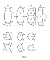
- Major piece 12 has a generally oval shape (please see Fig. 2a ), with the ends which are arranged, in a longitudinal direction, opposite each other being referred to as end portions 18 having an end contour 20.
- the two minor pieces 14, 16 consist of a connecting portion 22, the shape of which corresponds to the respective end portion 18 of major piece 12, and a generally elongate filling portion 24.
- the end portions 18, connecting portions 22 and filling portions 24 are portions on a piece typically made from a fabric. There is no disruption or other mechanical feature which distinguishes the end portions, connecting portions and filling portions on the level of the fabric.
- the two connecting portions 22 have the shape of a segment of a circle, ellipse, oval or similar form. In other words, they are delimited by a curved contour.
- the connecting portions 22 directly merge into the filling portions 24, with the contour having a break or sharp bend at the point where the contour of the connecting portion merges into the contour of the filling portion.
- the outer contour of the respective minor piece is later connected thereto.
- the outer contour of lower end portion 18 corresponds to the outer contour of connecting portion 22 of minor piece 16.
- the outer contour of the upper end portion 18 of major piece 12 corresponds to the outer contour of connecting portion 22 of minor piece 14.
- the shape and the dimensions (and therewith also the contour) of the two filling portions 24 of minor pieces 14, 16 correspond to each other.
- the two connecting portions 22 of minor piece 14, 16 could be formed identically.
- the outer contours of the end pieces 18 and the connecting pieces 22 are formed slightly different.
- the outer contour of minor piece 16 is formed with two slightly recessed portions 26 which can also be found on the respective end portion 18 of major piece 12.
- Fig. 2b shows different shapes of the major piece 12 and the minor pieces 14, 16.
- the main difference over the embodiment of Fig. 2a is a constriction 28 in the middle of the major piece 12.
- Fig. 2c shows an embodiment in which the major piece 12 is formed from two halves 30 which together form the major piece.
- major piece 12 is formed with a lateral protrusion 32 which results in a gas bag which is suitable for two passengers at the same time.
- minor piece 16 is arranged on major piece 12 such that the outer contour of connecting portion 22 of minor piece 16 coincides with end contour 20 of end portion 18 of major piece 12 (please see Figs. 3a and 3b ). Then, a seam 34 is formed along the outer contour of end portion 18 and connecting portion 22.
- minor piece 14 is connected in a similar manner to the other end portion 18, with the second minor piece 14 being connected to major piece 14 on a side which is opposite to the side at which minor piece 16 is arranged (see in particular Figs. 4a and 4b ).
- a seam 36 is used for connecting the respective end portion 18 with connecting portion 22 of minor piece 14.
- major piece 12 is folded along a center line L which divides the two halves of major piece 12 such that the half being provided with one of the minor pieces lies in the interior of a pocket formed by the other minor piece and the respective half of major piece 12.
- the half of major piece 12 provided with minor piece 14 is folded by 180° around line L such that minor piece 14 lies in the pocket formed between minor piece 16 and major piece 12, with major piece 12 being double-walled.
- Tether 40 can be formed from a separate fabric piece or could, in an alternative which is not depicted, be formed from extensions of major piece 14.
- a next step which is schematically depicted in Figs. 8a and 8b , filling portions 24 of minor pieces 14, 16 are folded along a bend line B so as to no longer be arranged on major piece 12, but to extend from the major piece.
- Bend line B is defined by the two ends of seams 34, 36.
- seams 38 are formed along the outer edges of major piece 12 and outer edges of filling portions 24, thereby closing the gas bag and leaving open only a filling opening 39.
- the rim of opening 39 can be used for attaching gas bag 10 to the vehicle roof.
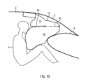
- FIGs. 10 and 11 the gas bag of Figs. 7a and 7b , comprising tether 40, is shown in an inflated condition (please see Fig. 10 ) and with vehicle occupant 5 being restrained (please see Fig. 11 ).
- Tether 40 divides gas bag 10 into an attachment portion 50 and a restraining portion 52. It can be seen in Fig. 11 that vehicle occupant 5 is restrained by restraining portion 52 to gas bag 10 only, and that attachment portion 50 acts basically as a feeding zone whose function is only to provide gas to restraining portion 52.
- constriction 54 which is formed by tether 40 results in the head of vehicle occupant 5 being smoothly supported without there being significant bending moments acting on the neck, the respective wall portion of restraining portion 52 to yield downwardly without being hindered by wall portions located above the head.
Description
- The invention relates to a gas bag for vehicles, having a flat, two-dimensional shape when being in an uninflated, vented condition and in a three-dimensional shape in an inflated condition. The invention relates in particular to a gas bag module with a gas bag which can be mounted at the roof of the vehicle and which, in an inflated condition, is arranged forward of a vehicle occupant, in particular between the windshield and the dashboard on the one hand and the vehicle occupant on the other hand.
- Gas bags which in an uninflated, vented condition have a two-dimensional shape offer advantages as regards their production. As the gas bag can be spread in a single plane, all fabric pieces from which the gas bag is made can be sewn together by using two-dimensional seams. These seams can simply be made when the pieces of the gas bag are spread out on a table.
-
JP 8230592 - The object of the invention is to provide a gas bag which can be manufactured by using a few pieces which are connected by a few seams, all seams being two-dimensional.
- This object is solved by a gas bag for vehicles, having a flat, two-dimensional shape when being in an uninflated, vented condition and a three-dimensional shape in an inflated condition, the gas bag having a main piece with opposite end portions, each of the end portions having an end contour, and two minor pieces which each have a connecting portion with a contour which corresponds to the end contour of the main piece, and which each have a filling portion, the two filling portions having similar shapes and similar dimensions.
- According to the invention, a tether is provided which divides the gas bag into an attachment portion and a restraining portion. Provision of the tether results in reduced loads acting on the head and neck of a vehicle occupant being restrained by the gas bag.
- This gas bag consists of three pieces only, which can be connected to each other by four seams. Accordingly, the gas bag can be manufactured at low cost.
- The invention also provides a method of sewing a gas bag which has a main piece with opposite end portions, each of the end portions having an end contour, and two minor pieces which each have a connecting portion with a contour which corresponds to the end contour of the main piece, and which each have a filling portion, the two filling portions having similar shapes and similar dimensions, the method comprising the following steps: First, the two minor pieces are sewn with their connecting pieces to the end portions of the main piece, a first of the minor pieces being sewn to a first surface of the main piece, while the second minor piece is being sewn to a second surface of the main piece. Then, the main piece is folded along its center line such that the first minor piece is inserted into a pocket between the second minor piece and the main piece such that the minor pieces lie one on top of the other. Then, the minor piece is folded along a line running through the end of the seams along the outer contour of the end portions of the main piece such that their filling portions form an extension of the main piece. Finally, seams are being formed along the outer edges of the main piece and along the edges of the connecting portions of the minor pieces. This method allows to manufacture the gas bag at low expenses.
- The invention also provides a gas bag module for frontal impact which is arranged at the roof of a vehicle close to the windscreen having a gas bag according to any of claim 1 to claim 11.
- Advantageous features of the invention are defined in the dependent claims.
- The invention will now be described with reference to two embodiments which are shown in the enclosed drawings. In the drawings
-
Figure 1 shows a gas bag according to a first embodiment of the invention, -
Figures 2a to 2c show different forms of the individual pieces from which the gas bag according toFig. 1 is formed, -
Figure 2d shows another form of the main piece which can be used for the gas bag ofFig. 1 , -
Figures 3a to 3c show the gas bag in a first manufacturing step in a top view, a side view and an enlarged top view, -
Figures 4a to 4c show in views similar toFig. 3 the gas bag in a second manufacturing step, -
Figures 5a and 5b show a third manufacturing step in a top view and a side view, -
Figures 6a and 6b show the gas bag in a condition after the third manufacturing step, -
Figures 7a and 7b show in views similar toFig. 6 a gas bag according to a second embodiment, -
Figures 8a and 8b show in a top view and a side view a fourth manufacturing step, -
Figures 9a and 9b show in a top view and a side view a fifth manufacturing step, -
Figure 10 shows in a schematic, sectional view a gas bag according to the second embodiment, and -
Figure 11 shows the gas bag ofFig. 10 at an enlarged scale. - In
Fig. 1 , part of a vehicle with aroof 2, awindshield 3 and adashboard 4 is shown. Further, avehicle occupant 5 is depicted. Atroof 2, a gas bag module with an inflator - not shown- and agas bag 10 is arranged. In the inflated condition shown inFig. 1 the gas bag extends betweenwindshield 3,dashboard 4 andvehicle occupant 5. -
Gas bag 10 is formed from three fabric pieces, namely amajor piece 12 and twominor pieces Major piece 12 has a generally oval shape (please seeFig. 2a ), with the ends which are arranged, in a longitudinal direction, opposite each other being referred to asend portions 18 having anend contour 20. The twominor pieces portion 22, the shape of which corresponds to therespective end portion 18 ofmajor piece 12, and a generallyelongate filling portion 24. Theend portions 18, connectingportions 22 and fillingportions 24 are portions on a piece typically made from a fabric. There is no disruption or other mechanical feature which distinguishes the end portions, connecting portions and filling portions on the level of the fabric. - The two connecting
portions 22 have the shape of a segment of a circle, ellipse, oval or similar form. In other words, they are delimited by a curved contour. The connectingportions 22 directly merge into thefilling portions 24, with the contour having a break or sharp bend at the point where the contour of the connecting portion merges into the contour of the filling portion. - The outer contour of the respective minor piece is later connected thereto. As can be seen in
Fig. 2a , the outer contour oflower end portion 18 corresponds to the outer contour of connectingportion 22 ofminor piece 16. In a similar manner, the outer contour of theupper end portion 18 ofmajor piece 12 corresponds to the outer contour of connectingportion 22 ofminor piece 14. Further, the shape and the dimensions (and therewith also the contour) of the two fillingportions 24 ofminor pieces - The two connecting
portions 22 ofminor piece minor pieces end portions 18 ofmajor piece 12, the outer contours of theend pieces 18 and the connectingpieces 22 are formed slightly different. In the shown embodiment, the outer contour ofminor piece 16 is formed with two slightlyrecessed portions 26 which can also be found on therespective end portion 18 ofmajor piece 12. -
Fig. 2b shows different shapes of themajor piece 12 and theminor pieces Fig. 2a is aconstriction 28 in the middle of themajor piece 12. -
Fig. 2c shows an embodiment in which themajor piece 12 is formed from twohalves 30 which together form the major piece. - In
Fig. 2d ,major piece 12 is formed with alateral protrusion 32 which results in a gas bag which is suitable for two passengers at the same time. - In a first step,
minor piece 16 is arranged onmajor piece 12 such that the outer contour of connectingportion 22 ofminor piece 16 coincides withend contour 20 ofend portion 18 of major piece 12 (please seeFigs. 3a and 3b ). Then, aseam 34 is formed along the outer contour ofend portion 18 and connectingportion 22. - In the next step,
minor piece 14 is connected in a similar manner to theother end portion 18, with the secondminor piece 14 being connected tomajor piece 14 on a side which is opposite to the side at whichminor piece 16 is arranged (see in particularFigs. 4a and 4b ). Aseam 36 is used for connecting therespective end portion 18 with connectingportion 22 ofminor piece 14. - In a next step which is depicted in
Figs. 5a and 5b ,major piece 12 is folded along a center line L which divides the two halves ofmajor piece 12 such that the half being provided with one of the minor pieces lies in the interior of a pocket formed by the other minor piece and the respective half ofmajor piece 12. As can be seen inFigs. 6a and 6b , the half ofmajor piece 12 provided withminor piece 14 is folded by 180° around line L such thatminor piece 14 lies in the pocket formed betweenminor piece 16 andmajor piece 12, withmajor piece 12 being double-walled. - In
Fig. 7a and 7b an alternative embodiment is shown which uses atether 40 provided betweenseam 32 andseam 34.Tether 40 can be formed from a separate fabric piece or could, in an alternative which is not depicted, be formed from extensions ofmajor piece 14. - In a next step which is schematically depicted in
Figs. 8a and 8b , fillingportions 24 ofminor pieces major piece 12, but to extend from the major piece. Bend line B is defined by the two ends ofseams Figs. 9a and 9b in whichmajor piece 12 is folded so as to lie flat in two layers, with connectingportions 22 ofminor pieces end portions 18, and with fillingportions 22 being folded away frommajor piece 12. In this condition in which the gas bag can be spread out flat in a plane, seams 38 are formed along the outer edges ofmajor piece 12 and outer edges of fillingportions 24, thereby closing the gas bag and leaving open only a fillingopening 39. The rim of opening 39 can be used for attachinggas bag 10 to the vehicle roof. - In
Figs. 10 and11 , the gas bag ofFigs. 7a and 7b , comprisingtether 40, is shown in an inflated condition (please seeFig. 10 ) and withvehicle occupant 5 being restrained (please seeFig. 11 ).Tether 40 dividesgas bag 10 into anattachment portion 50 and a restrainingportion 52. It can be seen inFig. 11 thatvehicle occupant 5 is restrained by restrainingportion 52 togas bag 10 only, and thatattachment portion 50 acts basically as a feeding zone whose function is only to provide gas to restrainingportion 52. The pronouncedconstriction 54 which is formed bytether 40 results in the head ofvehicle occupant 5 being smoothly supported without there being significant bending moments acting on the neck, the respective wall portion of restrainingportion 52 to yield downwardly without being hindered by wall portions located above the head.
Claims (11)
- A gas bag 10 for vehicles, having a flat, two-dimensional shape when being in an uninflated, vented condition and a three-dimensional shape in an inflated condition, the gas bag 10 having a main piece 12 with opposite end portions 18, each of the end portions 18 having a end contour 20, and two minor pieces 14, 16 which each have a connecting portion 22 with a contour with corresponds to the end contour of the main piece 12, and which each have a filling portion 24 the two filling portions 24 having similar shapes and similar dimensions, characterized in that a tether 40 is provided which divides the gas bag 10 into an attachment portion 50 and a restraining portion 52.
- The gas bag 10 of claim 1 wherein the opposite end portions have a similar shape and similar dimensions.
- The gas bag 10 of claim 1 or claim 2 wherein the main piece 12 has a constriction between the two opposite end portions 18.
- The gas bag 10 of claim 1 or claim 2 wherein the main piece 12 is formed from two halves.
- The gas bag of any of the preceding claim wherein the main piece 12 has a generally oval shape.
- The gas bag of any of the preceding claims wherein the main piece 12 has a lateral protrusion 32 between the two opposite end portions 18.
- The gas bag 10 of any of the preceding claims wherein the filling portion 24 of the minor pieces 14, 16 is generally elongate and the connecting portion is generally in the shape of a segment of a circle, ellipse or similar form.
- The gas bag 10 of any of the preceding claims wherein a first seam is provided between the main piece 12 and a first minor piece 14 along the end contour of the main piece 12, a second seam being provide between the main piece 12 and the second minor piece 16 along the respective end contour of the main piece 12 and third and forth seams being provided along the edges of the filling portions 24 of the first and second minor pieces 14, 16 and along the remaining edges of the main piece 12.
- The gas bag 10 of claim 1 wherein the tether 40 is a separate part attached to the main piece 12.
- The gas bag 10 of claim 1 wherein the tether 40 is formed as an integral extension of the main piece 12.
- A gas bag module for frontal impact which is arranged at the roof of a vehicle close to the windscreen having a gas bag according to any of claim 1 to claim 10.
Applications Claiming Priority (1)
| Application Number | Priority Date | Filing Date | Title |
|---|---|---|---|
| PCT/EP2011/001245 WO2012122997A1 (en) | 2011-03-14 | 2011-03-14 | Airbag device for motor vehicles |
Publications (2)
| Publication Number | Publication Date |
|---|---|
| EP2686206A1 EP2686206A1 (en) | 2014-01-22 |
| EP2686206B1 true EP2686206B1 (en) | 2014-11-12 |
Family
ID=44626137
Family Applications (1)
| Application Number | Title | Priority Date | Filing Date |
|---|---|---|---|
| EP11717471.4A Active EP2686206B1 (en) | 2011-03-14 | 2011-03-14 | Airbag device for motor vehicles |
Country Status (4)
| Country | Link |
|---|---|
| US (1) | US9533650B2 (en) |
| EP (1) | EP2686206B1 (en) |
| CN (1) | CN103442952B (en) |
| WO (1) | WO2012122997A1 (en) |
Cited By (1)
| Publication number | Priority date | Publication date | Assignee | Title |
|---|---|---|---|---|
| EP3483012A1 (en) | 2017-11-09 | 2019-05-15 | Autoliv Development AB | Frontal airbag unit and motor vehicle |
Families Citing this family (17)
| Publication number | Priority date | Publication date | Assignee | Title |
|---|---|---|---|---|
| CN102897134B (en) * | 2012-09-27 | 2016-09-14 | 锦州锦恒汽车安全系统有限公司 | A kind of air bag and auto-safety mechanism |
| TR201612906A2 (en) * | 2015-09-29 | 2017-04-21 | Ford Global Tech Llc | Airbag |
| KR102465666B1 (en) * | 2015-10-15 | 2022-11-10 | 현대모비스 주식회사 | Cushion of roof air bag device |
| US10703323B2 (en) | 2017-01-11 | 2020-07-07 | Zoox, Inc. | Occupant protection system including expandable curtain and/or expandable bladder |
| US11345300B2 (en) | 2018-03-01 | 2022-05-31 | ZF Passive Safety Systems US Inc. | Roof-mounted occupant restraint system |
| CN111886160A (en) | 2018-03-01 | 2020-11-03 | Zf被动安全系统美国公司 | Roof-mounted occupant restraint system |
| US11203321B2 (en) | 2018-03-29 | 2021-12-21 | Toyoda Gosei Co., Ltd. | Occupant protection device |
| US11858450B2 (en) | 2018-04-24 | 2024-01-02 | ZF Passive Safety Systems US Inc. | Roof-mounted occupant restraint system |
| US10953835B2 (en) | 2018-09-13 | 2021-03-23 | Trw Vehicle Safety Systems Inc. | Support for roof-mounted airbag |
| CN109774646B (en) * | 2019-03-13 | 2023-09-01 | 上海临港均胜汽车安全系统有限公司 | Overhead type air bag |
| US11059449B2 (en) | 2019-05-17 | 2021-07-13 | ZF Passive Safety Systems US Inc. | Roof-mounted occupant restraint system |
| US10967829B1 (en) | 2019-09-17 | 2021-04-06 | Joyson Safety Systems Acquisition Llc | Driver side airbag module |
| CN113060090B (en) * | 2019-12-31 | 2023-11-28 | 奥托立夫开发公司 | Head safety airbag of front row seat of automobile and automobile |
| US11685328B2 (en) * | 2021-04-29 | 2023-06-27 | Ford Global Technologies, Llc | Airbag having multiple inflation chambers supported on a dash |
| CN113602229B (en) * | 2021-08-30 | 2022-12-13 | 东风汽车有限公司东风日产乘用车公司 | Automobile roof air bag, air bag folding method, manufacturing method and automobile |
| US11577682B1 (en) | 2021-12-17 | 2023-02-14 | Zoox, Inc. | Vehicles and occupant protection systems having an expandable bladder with sequential deployment |
| US11780401B1 (en) | 2022-09-29 | 2023-10-10 | Zoox, Inc. | Vehicle occupant protection systems having frictionally engaging tether |
Family Cites Families (6)
| Publication number | Priority date | Publication date | Assignee | Title |
|---|---|---|---|---|
| US5316337A (en) | 1992-03-30 | 1994-05-31 | Toyo Tire & Rubber Co., Ltd. | Inflatable bags for airbag passive restraint systems for front seat passenger and methods for manufacturing thereof |
| JPH07291069A (en) * | 1994-04-26 | 1995-11-07 | Takata Kk | Air bag |
| JPH08230592A (en) * | 1994-12-27 | 1996-09-10 | Bridgestone Corp | Air bag |
| DE29804611U1 (en) | 1998-03-09 | 1998-05-20 | Petri Ag | Airbag module, especially passenger airbag module |
| US7048304B1 (en) * | 2000-08-18 | 2006-05-23 | Milliken & Company | Multiple panel airbag and method |
| DE102008057968A1 (en) | 2008-11-19 | 2010-05-20 | Trw Automotive Gmbh | airbag |
-
2011
- 2011-03-14 EP EP11717471.4A patent/EP2686206B1/en active Active
- 2011-03-14 US US14/001,724 patent/US9533650B2/en active Active
- 2011-03-14 WO PCT/EP2011/001245 patent/WO2012122997A1/en active Application Filing
- 2011-03-14 CN CN201180069254.3A patent/CN103442952B/en active Active
Cited By (3)
| Publication number | Priority date | Publication date | Assignee | Title |
|---|---|---|---|---|
| EP3483012A1 (en) | 2017-11-09 | 2019-05-15 | Autoliv Development AB | Frontal airbag unit and motor vehicle |
| WO2019091781A1 (en) | 2017-11-09 | 2019-05-16 | Autoliv Development Ab | Frontal airbag unit and motor vehicle |
| CN111356614A (en) * | 2017-11-09 | 2020-06-30 | 奥托立夫开发公司 | Front airbag unit and motor vehicle |
Also Published As
| Publication number | Publication date |
|---|---|
| US20140232092A1 (en) | 2014-08-21 |
| EP2686206A1 (en) | 2014-01-22 |
| WO2012122997A1 (en) | 2012-09-20 |
| CN103442952A (en) | 2013-12-11 |
| US9533650B2 (en) | 2017-01-03 |
| CN103442952B (en) | 2016-08-24 |
Similar Documents
| Publication | Publication Date | Title |
|---|---|---|
| EP2686206B1 (en) | Airbag device for motor vehicles | |
| US11919468B2 (en) | Side airbag and vehicle-occupant restraint system having a side airbag | |
| US10618492B2 (en) | Inflatable airbag for protecting a person, and airbag module, vehicle parts and vehicle occupant restraint system having such an airbag | |
| JP5357977B2 (en) | Knee airbag | |
| WO2010092454A8 (en) | Side airbag system and method of manufacturing side airbag | |
| CN107848486B (en) | Inflatable airbag for protecting a person, airbag module, vehicle occupant restraint system comprising such an airbag and method of manufacturing an inflatable airbag | |
| CN103228491B (en) | Automobile seat containing side-airbag device | |
| US20170158158A1 (en) | Chambered side impact airbag | |
| CN104602972A (en) | Vehicle side air bag device | |
| CN101253078A (en) | Pedestrian airbag and pedestrian airbag device | |
| CN104602973A (en) | Vehicle side airbag device and method for producing side airbag | |
| CN105377638A (en) | Side airbag device for vehicle | |
| CN104487294A (en) | Side airbag device for use in vehicle | |
| US20160200279A1 (en) | Method for protecting a vehicle occupant, and airbag | |
| CN109941221B (en) | Air bag, air bag system and car | |
| EP2492156A1 (en) | Pedestrian protection airbag for a vehicle | |
| CN108177627B (en) | Wrap-up type automobile safety airbag structure | |
| JP2018114879A (en) | Driver seat airbag and driver seat air bag device | |
| CN106553608A (en) | Including the front side airbag to steam vent | |
| CN107000673B (en) | Pedestrian airbag apparatus and automobile | |
| EP1256491A3 (en) | Head-protecting bag device for occupants in an automobile | |
| US11186249B2 (en) | Passenger airbag | |
| JP2016145011A (en) | Curtain airbag | |
| CN106029451A (en) | Mounting envelope | |
| CN105579300B (en) | Air bag |
Legal Events
| Date | Code | Title | Description |
|---|---|---|---|
| PUAI | Public reference made under article 153(3) epc to a published international application that has entered the european phase |
Free format text: ORIGINAL CODE: 0009012 |
|
| 17P | Request for examination filed |
Effective date: 20131014 |
|
| AK | Designated contracting states |
Kind code of ref document: A1 Designated state(s): AL AT BE BG CH CY CZ DE DK EE ES FI FR GB GR HR HU IE IS IT LI LT LU LV MC MK MT NL NO PL PT RO RS SE SI SK SM TR |
|
| DAX | Request for extension of the european patent (deleted) | ||
| GRAP | Despatch of communication of intention to grant a patent |
Free format text: ORIGINAL CODE: EPIDOSNIGR1 |
|
| INTG | Intention to grant announced |
Effective date: 20140708 |
|
| GRAS | Grant fee paid |
Free format text: ORIGINAL CODE: EPIDOSNIGR3 |
|
| GRAA | (expected) grant |
Free format text: ORIGINAL CODE: 0009210 |
|
| AK | Designated contracting states |
Kind code of ref document: B1 Designated state(s): AL AT BE BG CH CY CZ DE DK EE ES FI FR GB GR HR HU IE IS IT LI LT LU LV MC MK MT NL NO PL PT RO RS SE SI SK SM TR |
|
| REG | Reference to a national code |
Ref country code: GB Ref legal event code: FG4D |
|
| REG | Reference to a national code |
Ref country code: CH Ref legal event code: EP |
|
| REG | Reference to a national code |
Ref country code: AT Ref legal event code: REF Ref document number: 695533 Country of ref document: AT Kind code of ref document: T Effective date: 20141115 |
|
| REG | Reference to a national code |
Ref country code: IE Ref legal event code: FG4D |
|
| REG | Reference to a national code |
Ref country code: DE Ref legal event code: R096 Ref document number: 602011011300 Country of ref document: DE Effective date: 20141224 |
|
| REG | Reference to a national code |
Ref country code: NL Ref legal event code: VDEP Effective date: 20141112 |
|
| REG | Reference to a national code |
Ref country code: AT Ref legal event code: MK05 Ref document number: 695533 Country of ref document: AT Kind code of ref document: T Effective date: 20141112 |
|
| PG25 | Lapsed in a contracting state [announced via postgrant information from national office to epo] |
Ref country code: NL Free format text: LAPSE BECAUSE OF FAILURE TO SUBMIT A TRANSLATION OF THE DESCRIPTION OR TO PAY THE FEE WITHIN THE PRESCRIBED TIME-LIMIT Effective date: 20141112 Ref country code: IS Free format text: LAPSE BECAUSE OF FAILURE TO SUBMIT A TRANSLATION OF THE DESCRIPTION OR TO PAY THE FEE WITHIN THE PRESCRIBED TIME-LIMIT Effective date: 20150312 Ref country code: NO Free format text: LAPSE BECAUSE OF FAILURE TO SUBMIT A TRANSLATION OF THE DESCRIPTION OR TO PAY THE FEE WITHIN THE PRESCRIBED TIME-LIMIT Effective date: 20150212 Ref country code: PT Free format text: LAPSE BECAUSE OF FAILURE TO SUBMIT A TRANSLATION OF THE DESCRIPTION OR TO PAY THE FEE WITHIN THE PRESCRIBED TIME-LIMIT Effective date: 20150312 Ref country code: ES Free format text: LAPSE BECAUSE OF FAILURE TO SUBMIT A TRANSLATION OF THE DESCRIPTION OR TO PAY THE FEE WITHIN THE PRESCRIBED TIME-LIMIT Effective date: 20141112 Ref country code: FI Free format text: LAPSE BECAUSE OF FAILURE TO SUBMIT A TRANSLATION OF THE DESCRIPTION OR TO PAY THE FEE WITHIN THE PRESCRIBED TIME-LIMIT Effective date: 20141112 Ref country code: LT Free format text: LAPSE BECAUSE OF FAILURE TO SUBMIT A TRANSLATION OF THE DESCRIPTION OR TO PAY THE FEE WITHIN THE PRESCRIBED TIME-LIMIT Effective date: 20141112 |
|
| PG25 | Lapsed in a contracting state [announced via postgrant information from national office to epo] |
Ref country code: RS Free format text: LAPSE BECAUSE OF FAILURE TO SUBMIT A TRANSLATION OF THE DESCRIPTION OR TO PAY THE FEE WITHIN THE PRESCRIBED TIME-LIMIT Effective date: 20141112 Ref country code: LV Free format text: LAPSE BECAUSE OF FAILURE TO SUBMIT A TRANSLATION OF THE DESCRIPTION OR TO PAY THE FEE WITHIN THE PRESCRIBED TIME-LIMIT Effective date: 20141112 Ref country code: CY Free format text: LAPSE BECAUSE OF FAILURE TO SUBMIT A TRANSLATION OF THE DESCRIPTION OR TO PAY THE FEE WITHIN THE PRESCRIBED TIME-LIMIT Effective date: 20141112 Ref country code: PL Free format text: LAPSE BECAUSE OF FAILURE TO SUBMIT A TRANSLATION OF THE DESCRIPTION OR TO PAY THE FEE WITHIN THE PRESCRIBED TIME-LIMIT Effective date: 20141112 Ref country code: HR Free format text: LAPSE BECAUSE OF FAILURE TO SUBMIT A TRANSLATION OF THE DESCRIPTION OR TO PAY THE FEE WITHIN THE PRESCRIBED TIME-LIMIT Effective date: 20141112 Ref country code: AT Free format text: LAPSE BECAUSE OF FAILURE TO SUBMIT A TRANSLATION OF THE DESCRIPTION OR TO PAY THE FEE WITHIN THE PRESCRIBED TIME-LIMIT Effective date: 20141112 Ref country code: SE Free format text: LAPSE BECAUSE OF FAILURE TO SUBMIT A TRANSLATION OF THE DESCRIPTION OR TO PAY THE FEE WITHIN THE PRESCRIBED TIME-LIMIT Effective date: 20141112 |
|
| PG25 | Lapsed in a contracting state [announced via postgrant information from national office to epo] |
Ref country code: EE Free format text: LAPSE BECAUSE OF FAILURE TO SUBMIT A TRANSLATION OF THE DESCRIPTION OR TO PAY THE FEE WITHIN THE PRESCRIBED TIME-LIMIT Effective date: 20141112 Ref country code: SK Free format text: LAPSE BECAUSE OF FAILURE TO SUBMIT A TRANSLATION OF THE DESCRIPTION OR TO PAY THE FEE WITHIN THE PRESCRIBED TIME-LIMIT Effective date: 20141112 Ref country code: DK Free format text: LAPSE BECAUSE OF FAILURE TO SUBMIT A TRANSLATION OF THE DESCRIPTION OR TO PAY THE FEE WITHIN THE PRESCRIBED TIME-LIMIT Effective date: 20141112 Ref country code: RO Free format text: LAPSE BECAUSE OF FAILURE TO SUBMIT A TRANSLATION OF THE DESCRIPTION OR TO PAY THE FEE WITHIN THE PRESCRIBED TIME-LIMIT Effective date: 20141112 Ref country code: CZ Free format text: LAPSE BECAUSE OF FAILURE TO SUBMIT A TRANSLATION OF THE DESCRIPTION OR TO PAY THE FEE WITHIN THE PRESCRIBED TIME-LIMIT Effective date: 20141112 |
|
| REG | Reference to a national code |
Ref country code: DE Ref legal event code: R097 Ref document number: 602011011300 Country of ref document: DE |
|
| PLBE | No opposition filed within time limit |
Free format text: ORIGINAL CODE: 0009261 |
|
| STAA | Information on the status of an ep patent application or granted ep patent |
Free format text: STATUS: NO OPPOSITION FILED WITHIN TIME LIMIT |
|
| 26N | No opposition filed |
Effective date: 20150813 |
|
| PG25 | Lapsed in a contracting state [announced via postgrant information from national office to epo] |
Ref country code: MC Free format text: LAPSE BECAUSE OF FAILURE TO SUBMIT A TRANSLATION OF THE DESCRIPTION OR TO PAY THE FEE WITHIN THE PRESCRIBED TIME-LIMIT Effective date: 20141112 Ref country code: LU Free format text: LAPSE BECAUSE OF FAILURE TO SUBMIT A TRANSLATION OF THE DESCRIPTION OR TO PAY THE FEE WITHIN THE PRESCRIBED TIME-LIMIT Effective date: 20150314 |
|
| REG | Reference to a national code |
Ref country code: CH Ref legal event code: PL |
|
| GBPC | Gb: european patent ceased through non-payment of renewal fee |
Effective date: 20150314 |
|
| PG25 | Lapsed in a contracting state [announced via postgrant information from national office to epo] |
Ref country code: IT Free format text: LAPSE BECAUSE OF FAILURE TO SUBMIT A TRANSLATION OF THE DESCRIPTION OR TO PAY THE FEE WITHIN THE PRESCRIBED TIME-LIMIT Effective date: 20141112 |
|
| REG | Reference to a national code |
Ref country code: IE Ref legal event code: MM4A |
|
| PG25 | Lapsed in a contracting state [announced via postgrant information from national office to epo] |
Ref country code: CH Free format text: LAPSE BECAUSE OF NON-PAYMENT OF DUE FEES Effective date: 20150331 Ref country code: IE Free format text: LAPSE BECAUSE OF NON-PAYMENT OF DUE FEES Effective date: 20150314 Ref country code: GB Free format text: LAPSE BECAUSE OF NON-PAYMENT OF DUE FEES Effective date: 20150314 Ref country code: LI Free format text: LAPSE BECAUSE OF NON-PAYMENT OF DUE FEES Effective date: 20150331 |
|
| PG25 | Lapsed in a contracting state [announced via postgrant information from national office to epo] |
Ref country code: SI Free format text: LAPSE BECAUSE OF FAILURE TO SUBMIT A TRANSLATION OF THE DESCRIPTION OR TO PAY THE FEE WITHIN THE PRESCRIBED TIME-LIMIT Effective date: 20141112 |
|
| REG | Reference to a national code |
Ref country code: FR Ref legal event code: PLFP Year of fee payment: 6 |
|
| PG25 | Lapsed in a contracting state [announced via postgrant information from national office to epo] |
Ref country code: MT Free format text: LAPSE BECAUSE OF FAILURE TO SUBMIT A TRANSLATION OF THE DESCRIPTION OR TO PAY THE FEE WITHIN THE PRESCRIBED TIME-LIMIT Effective date: 20141112 |
|
| REG | Reference to a national code |
Ref country code: FR Ref legal event code: PLFP Year of fee payment: 7 |
|
| PG25 | Lapsed in a contracting state [announced via postgrant information from national office to epo] |
Ref country code: HU Free format text: LAPSE BECAUSE OF FAILURE TO SUBMIT A TRANSLATION OF THE DESCRIPTION OR TO PAY THE FEE WITHIN THE PRESCRIBED TIME-LIMIT; INVALID AB INITIO Effective date: 20110314 Ref country code: SM Free format text: LAPSE BECAUSE OF FAILURE TO SUBMIT A TRANSLATION OF THE DESCRIPTION OR TO PAY THE FEE WITHIN THE PRESCRIBED TIME-LIMIT Effective date: 20141112 Ref country code: BG Free format text: LAPSE BECAUSE OF FAILURE TO SUBMIT A TRANSLATION OF THE DESCRIPTION OR TO PAY THE FEE WITHIN THE PRESCRIBED TIME-LIMIT Effective date: 20141112 |
|
| PG25 | Lapsed in a contracting state [announced via postgrant information from national office to epo] |
Ref country code: GR Free format text: LAPSE BECAUSE OF FAILURE TO SUBMIT A TRANSLATION OF THE DESCRIPTION OR TO PAY THE FEE WITHIN THE PRESCRIBED TIME-LIMIT Effective date: 20141112 |
|
| PG25 | Lapsed in a contracting state [announced via postgrant information from national office to epo] |
Ref country code: TR Free format text: LAPSE BECAUSE OF FAILURE TO SUBMIT A TRANSLATION OF THE DESCRIPTION OR TO PAY THE FEE WITHIN THE PRESCRIBED TIME-LIMIT Effective date: 20141112 |
|
| PG25 | Lapsed in a contracting state [announced via postgrant information from national office to epo] |
Ref country code: BE Free format text: LAPSE BECAUSE OF FAILURE TO SUBMIT A TRANSLATION OF THE DESCRIPTION OR TO PAY THE FEE WITHIN THE PRESCRIBED TIME-LIMIT Effective date: 20141112 |
|
| REG | Reference to a national code |
Ref country code: FR Ref legal event code: PLFP Year of fee payment: 8 |
|
| PG25 | Lapsed in a contracting state [announced via postgrant information from national office to epo] |
Ref country code: MK Free format text: LAPSE BECAUSE OF FAILURE TO SUBMIT A TRANSLATION OF THE DESCRIPTION OR TO PAY THE FEE WITHIN THE PRESCRIBED TIME-LIMIT Effective date: 20141112 |
|
| PG25 | Lapsed in a contracting state [announced via postgrant information from national office to epo] |
Ref country code: AL Free format text: LAPSE BECAUSE OF FAILURE TO SUBMIT A TRANSLATION OF THE DESCRIPTION OR TO PAY THE FEE WITHIN THE PRESCRIBED TIME-LIMIT Effective date: 20141112 |
|
| PGFP | Annual fee paid to national office [announced via postgrant information from national office to epo] |
Ref country code: FR Payment date: 20230110 Year of fee payment: 13 |
|
| PGFP | Annual fee paid to national office [announced via postgrant information from national office to epo] |
Ref country code: DE Payment date: 20230331 Year of fee payment: 13 |
|
| P01 | Opt-out of the competence of the unified patent court (upc) registered |
Effective date: 20230528 |