EP2686080B1 - Illuminated balloon - Google Patents
Illuminated balloon Download PDFInfo
- Publication number
- EP2686080B1 EP2686080B1 EP12712710.8A EP12712710A EP2686080B1 EP 2686080 B1 EP2686080 B1 EP 2686080B1 EP 12712710 A EP12712710 A EP 12712710A EP 2686080 B1 EP2686080 B1 EP 2686080B1
- Authority
- EP
- European Patent Office
- Prior art keywords
- balloon
- sheet
- illumination device
- sheets
- wall
- Prior art date
- Legal status (The legal status is an assumption and is not a legal conclusion. Google has not performed a legal analysis and makes no representation as to the accuracy of the status listed.)
- Active
Links
Images


Classifications
-
- A—HUMAN NECESSITIES
- A63—SPORTS; GAMES; AMUSEMENTS
- A63H—TOYS, e.g. TOPS, DOLLS, HOOPS OR BUILDING BLOCKS
- A63H27/00—Toy aircraft; Other flying toys
- A63H27/10—Balloons
-
- B—PERFORMING OPERATIONS; TRANSPORTING
- B64—AIRCRAFT; AVIATION; COSMONAUTICS
- B64B—LIGHTER-THAN AIR AIRCRAFT
- B64B1/00—Lighter-than-air aircraft
- B64B1/40—Balloons
-
- A—HUMAN NECESSITIES
- A63—SPORTS; GAMES; AMUSEMENTS
- A63H—TOYS, e.g. TOPS, DOLLS, HOOPS OR BUILDING BLOCKS
- A63H27/00—Toy aircraft; Other flying toys
- A63H27/10—Balloons
- A63H2027/1058—Balloons associated with light or sound
-
- B—PERFORMING OPERATIONS; TRANSPORTING
- B64—AIRCRAFT; AVIATION; COSMONAUTICS
- B64D—EQUIPMENT FOR FITTING IN OR TO AIRCRAFT; FLIGHT SUITS; PARACHUTES; ARRANGEMENT OR MOUNTING OF POWER PLANTS OR PROPULSION TRANSMISSIONS IN AIRCRAFT
- B64D2203/00—Aircraft or airfield lights using LEDs
Definitions
- the present invention concerns a balloon comprising a flexible wall which is at least partially transparent or translucent and which has an illumination device mounted onto the wall inside the balloon cavity.
- the applicant's earlier patent specification WO 2008/110832 discloses a party balloon, that is to say a toy balloon, having an illumination device mounted inside, the illumination device comprising a light emitting diode (LED) powered by at least one battery.
- the LED lights up when a strip of insulating material is withdrawn from between the battery and the LED to complete the circuit and the balloon is thereby illuminated from its interior.
- a switch may be provided which can be manually actuated to connect or disconnect a light source from its power source thereby selectively to illuminate the balloon cavity.
- the illumination device is mounted to the inside of the balloon wall by having a projection which is engaged from outside the balloon by an attachment element, such as a clip or a band, more specifically an O-ring of elastic material.
- an attachment element such as a clip or a band, more specifically an O-ring of elastic material.
- the manner of mounting the illumination device inside the wall by means of a projection engaged from outside by a clip or band or similar is also applicable to a balloon formed from two sheets of flexible material connected around their edges, the sheeting being formed of substantially inelastic material, such as metallised plastics material or Mylar.
- an illumination device to the wall of a balloon
- the device may be attached by adhesive when the balloon wall material is of the substantially inelastic type.
- the illumination device should only operate once the balloon is inflated so as to light up the inflated balloon.
- the illumination device which has been mounted inside may be flung out at some speed.
- An object of the present invention is to reduce the speed of any projectile resulting from a bursting balloon, such as a flying or falling illumination device.
- the present invention provides a balloon comprising a flexible wall defining a balloon cavity and having an inlet portion defining an opening into the balloon cavity through which gas under pressure can be directed to inflate the balloon, said wall being at least partially transparent or translucent, an illumination device including a light emitting member which is mounted to the wall inside the balloon cavity; and a sheet of flexible material connected to the illumination device inside the balloon cavity, this sheet being configured to serve as a parachute for the illumination device in the event of rupture of the wall of the balloon when in an inflated condition.
- parachute as used herein is defined as an umbrella shaped piece of fabric of high drag to retard the descent of a falling body or reduce the speed of a moving/flying body.
- a second sheet of flexible material is connected to the illumination device inside the balloon cavity, the first and second sheets together serving as the parachute.
- An arrangement which is particularly advantageous for efficient production of balloons incorporating such a two sheet parachute is that the first and second sheets should have a common connection to the illumination device. Furthermore the first and second sheets preferably overlie each other for at least about half of their respective areas.
- the parachute may be formed by a single sheet, or by three sheets of flexible material, or more than three sheets.
- One particular practical embodiment of the balloon of the invention is a balloon 10 formed of latex which is inherently transparent or translucent when it is stretched when the balloon is inflated.
- An illumination device 20 is mounted onto the wall of the balloon, inside the balloon, at a location generally opposite to the inlet portion through which the balloon is inflated in use.
- the precise form of the illumination device 20 is not important to the present invention but it will typically include an LED or other light source and at least one battery power source to which the light source is connected in use, for example by removal of a strip of insulating material, an end of which is initially interposed between contacts for the light source and battery.
- the LED and battery or batteries are mounted in a frame or housing which provides a projection 12 enabling attachment of the illumination device.
- the projection is typically formed with a neck portion 14 and an enlarged head 16.
- An enlarged head 16 in the form of a flat circular disc, namely a short cylindrical form, is particularly suitable and is the form shown in the accompanying Figs. 3 and 4 .
- other configurations are possible.
- An elastic band (rubber band) 18 engages over the projection 12 from outside the balloon wall, seating into the neck portion 14 to reliably hold the illumination device 20. As shown in Figs. 3 and 4 the band 18 is typically twisted several times as it is applied in order to make a tight connection between the balloon material 10 and the neck 14 of the illumination device 20.
- Two sheets of polyethylene 22, 24, as shown in figure 2 are attached to the illumination device 20 to serve as a parachute for the device 20 in the event of bursting of the inflated balloon.
- the sheets are square sheets of low density polyethylene of a size 85mm x 85mm. This size is chosen as about the maximum permissible to avoid being considered as a choking or suffocation hazard in respect of a balloon which has burst and may be picked up by children.
- a suitable thickness of polyethylene is from 0.03mm to 0.05mm, again around the maximum permissible for the same safety reason.
- the two sheets 22, 24 are each connected at a generally central position to the end of the illumination device. They overlie each other to a considerable extent, for at least half their respective areas. Preferably, as shown in Fig. 2 , they are orientated to be offset through 90° relative to each other.
- each sheet 22, 24 is provided with a small hole 26 at a central location and this is passed over the head portion 16 of the projection 12 of the illumination device 20 before the illumination device is secured to the inside of the balloon wall.
- the sheets 22, 24 are held in position by the same band 18 which secures the illumination device 20.
- the sheets remain 22, 24 attached to the illumination device 20, namely the aforementioned LED module, and the relevant fragment of balloon wall, and serve as a parachute, slowing the speed of the LED module and reducing the force of any impact it makes. This is illustrated schematically in Fig. 5 .
- the LED module 20 When such a balloon bursts from a full inflated condition, the LED module 20 may be hurled in any direction at a speed of about 30m sec -1 in reaction to the release of the pressurised gas. Tests have shown that with the provision of a parachute of this form the velocity of the LED module 20 may be reduced, typically by 30%, but even by as much as 70%, thereby reducing risk of any damage or injury being caused as a result of impact of the module.
- a single sheet of flexible material may provide the parachute or three or more sheets of flexible material, overlying each other to some extent, may provide the parachute.
- a single sheet of polyethylene 30 provides the parachute and this sheet is formed with reinforcing ribs 28 extending from a central region towards the edge of the sheet.
- the reference numerals used to designate other parts are the same as in the preceding figures as these parts correspond.
- With a square or rectangular sheet such ribs 28 are suitably four in number, extending towards the respective corners.
- the purpose of these ribs 28 is to ensure that as the sheet 30 forms the parachute, upon bursting of the inflated balloon 10, it opens out and remains spread outwards without tending to fold back on itself. In this respect it is generally preferred that the sheet 30 extends from the central connection to the LED module 20 at an angle between 170° to 180°.
- the ribs 28 facilitate this.
- the ribs 28 are preferably provided on the surface of the sheet 30 facing towards the balloon wall in the initial assembled un-inflated and subsequently inflated condition.
- the ribs 28 may introduce a certain curvature to the shape of the deployed parachute, as shown in figure 7 .
- the ribs 28 are preferably of such height/thickness and have ends sufficiently close to the head 16 of the projection 12 that those ends contact the projection as the parachute spreads and inhibit opening of the sheet 30 (or multiple sheets in other embodiments) beyond a predetermined angle, such as 180°.
- the ribs may taper in height/thickness from adjacent the centre towards the edge of the sheet so that the ends of ribs at the centre are high enough to provide the required abutment to prevent opening beyond 180°. Such tapering may also result in helpful curvature of the deployed parachute configuration.
- the parachute there may be only a single sheet forming the parachute or there may be two, three or more than three sheets.
- the sheet or sheets need not be square, and may be circular or any other shape found to be suitable.
- the exact size, thickness and composition of the sheet material may vary and will be selected to optimise performance and ease of assembly of the illuminated balloon product and minimise cost.
- ribs any suitable number may be provided. For example, in respect of a circular sheet, three equally spaced ribs may be sufficient.
- the invention is applicable to all types of balloon, including balloons of other material, particularly inelastic material, and balloons which are for other purposes than as toys or party decorations.
- the sheet or sheets providing the parachute may be connected to the illumination device in a manner different to that described above in respect of the illustrated embodiments, and the illumination device itself may be attached to the wall of the balloon in a manner different to that described above in respect of the illustrated embodiments.
Landscapes
- Engineering & Computer Science (AREA)
- Mechanical Engineering (AREA)
- Aviation & Aerospace Engineering (AREA)
- Toys (AREA)
- Illuminated Signs And Luminous Advertising (AREA)
- Securing Globes, Refractors, Reflectors Or The Like (AREA)
Description
- The present invention concerns a balloon comprising a flexible wall which is at least partially transparent or translucent and which has an illumination device mounted onto the wall inside the balloon cavity.
- The applicant's earlier patent specification
WO 2008/110832 discloses a party balloon, that is to say a toy balloon, having an illumination device mounted inside, the illumination device comprising a light emitting diode (LED) powered by at least one battery. The LED lights up when a strip of insulating material is withdrawn from between the battery and the LED to complete the circuit and the balloon is thereby illuminated from its interior. - In other versions of illuminated balloon, a switch may be provided which can be manually actuated to connect or disconnect a light source from its power source thereby selectively to illuminate the balloon cavity.
- In the applicant's known party balloon the illumination device is mounted to the inside of the balloon wall by having a projection which is engaged from outside the balloon by an attachment element, such as a clip or a band, more specifically an O-ring of elastic material. Projections in the form of a partially spherical button or, more preferably a flattened button, were proposed.
- Although the applicant's earlier specification is primarily concerned with a balloon formed in one piece of elastomeric material, such as latex, the manner of mounting the illumination device inside the wall by means of a projection engaged from outside by a clip or band or similar is also applicable to a balloon formed from two sheets of flexible material connected around their edges, the sheeting being formed of substantially inelastic material, such as metallised plastics material or Mylar.
- However, other means of mounting an illumination device to the wall of a balloon are possible. For example the device may be attached by adhesive when the balloon wall material is of the substantially inelastic type.
- Typically it is intended that the illumination device should only operate once the balloon is inflated so as to light up the inflated balloon.
- In the event that the balloon bursts when inflated, the illumination device which has been mounted inside may be flung out at some speed.
- An object of the present invention is to reduce the speed of any projectile resulting from a bursting balloon, such as a flying or falling illumination device.
- The present invention provides a balloon comprising a flexible wall defining a balloon cavity and having an inlet portion defining an opening into the balloon cavity through which gas under pressure can be directed to inflate the balloon, said wall being at least partially transparent or translucent, an illumination device including a light emitting member which is mounted to the wall inside the balloon cavity; and a sheet of flexible material connected to the illumination device inside the balloon cavity, this sheet being configured to serve as a parachute for the illumination device in the event of rupture of the wall of the balloon when in an inflated condition.
- The term "parachute" as used herein is defined as an umbrella shaped piece of fabric of high drag to retard the descent of a falling body or reduce the speed of a moving/flying body.
- In preferred embodiments a second sheet of flexible material is connected to the illumination device inside the balloon cavity, the first and second sheets together serving as the parachute. An arrangement which is particularly advantageous for efficient production of balloons incorporating such a two sheet parachute is that the first and second sheets should have a common connection to the illumination device. Furthermore the first and second sheets preferably overlie each other for at least about half of their respective areas.
- In other embodiments the parachute may be formed by a single sheet, or by three sheets of flexible material, or more than three sheets.
- The invention will be described further, by way of example, with reference to the accompanying drawings, in which:
-
Fig. 1 shows a sheet of material for forming the parachute structure; -
Fig. 2 is a reduced scale plan view showing the positioning of two sheets when forming the parachute structure; -
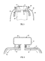
Fig. 3 is a fragmentary cross-section sketch showing how the parachute structure and balloon wall are to be attached to the illumination device; -
Fig. 4 is a similar view toFig. 3 , but of enlarged scale, showing the same component parts when the connection is completed; -
Fig. 5 is a sketch showing the balloon with the parachute structure after it has been inflated and has exploded; and -
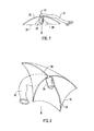
Fig. 6 is a sketch showing a modified embodiment of a balloon in accordance with the invention in un-inflated condition; -
Fig. 7 shows the balloon offigure 6 after inflation and rupture; and -
Fig. 8 shows a slightly different view and to a larger scale of the balloon offigure 6 after inflation and rupture. - One particular practical embodiment of the balloon of the invention is a
balloon 10 formed of latex which is inherently transparent or translucent when it is stretched when the balloon is inflated. Anillumination device 20 is mounted onto the wall of the balloon, inside the balloon, at a location generally opposite to the inlet portion through which the balloon is inflated in use. - The precise form of the
illumination device 20 is not important to the present invention but it will typically include an LED or other light source and at least one battery power source to which the light source is connected in use, for example by removal of a strip of insulating material, an end of which is initially interposed between contacts for the light source and battery. The LED and battery or batteries are mounted in a frame or housing which provides aprojection 12 enabling attachment of the illumination device. The projection is typically formed with aneck portion 14 and an enlargedhead 16. An enlargedhead 16 in the form of a flat circular disc, namely a short cylindrical form, is particularly suitable and is the form shown in the accompanyingFigs. 3 and 4 . However, other configurations are possible. An elastic band (rubber band) 18 engages over theprojection 12 from outside the balloon wall, seating into theneck portion 14 to reliably hold theillumination device 20. As shown inFigs. 3 and 4 theband 18 is typically twisted several times as it is applied in order to make a tight connection between theballoon material 10 and theneck 14 of theillumination device 20. - Two sheets of
polyethylene figure 2 , are attached to theillumination device 20 to serve as a parachute for thedevice 20 in the event of bursting of the inflated balloon. By way of example, and as shown inFigs. 1 and 2 , the sheets are square sheets of low density polyethylene of a size 85mm x 85mm. This size is chosen as about the maximum permissible to avoid being considered as a choking or suffocation hazard in respect of a balloon which has burst and may be picked up by children. A suitable thickness of polyethylene is from 0.03mm to 0.05mm, again around the maximum permissible for the same safety reason. The twosheets Fig. 2 , they are orientated to be offset through 90° relative to each other. - To make the connection each
sheet small hole 26 at a central location and this is passed over thehead portion 16 of theprojection 12 of theillumination device 20 before the illumination device is secured to the inside of the balloon wall. In the subsequent manufacturing step, shown inFigs. 3 and 4 , thesheets same band 18 which secures theillumination device 20. Then in the event of explosion of theballoon 10 after it has been inflated, the sheets remain 22, 24 attached to theillumination device 20, namely the aforementioned LED module, and the relevant fragment of balloon wall, and serve as a parachute, slowing the speed of the LED module and reducing the force of any impact it makes. This is illustrated schematically inFig. 5 . - When such a balloon bursts from a full inflated condition, the
LED module 20 may be hurled in any direction at a speed of about 30m sec-1 in reaction to the release of the pressurised gas. Tests have shown that with the provision of a parachute of this form the velocity of theLED module 20 may be reduced, typically by 30%, but even by as much as 70%, thereby reducing risk of any damage or injury being caused as a result of impact of the module. - The aforesaid description is illustrative, not limitative, of the invention and many variations are possible within the scope of the appended claims. As previously mentioned in other embodiments a single sheet of flexible material may provide the parachute or three or more sheets of flexible material, overlying each other to some extent, may provide the parachute.
- In a modified embodiment illustrated in
Figs. 6 to 8 , a single sheet ofpolyethylene 30 provides the parachute and this sheet is formed with reinforcingribs 28 extending from a central region towards the edge of the sheet. The reference numerals used to designate other parts are the same as in the preceding figures as these parts correspond. With a square or rectangular sheetsuch ribs 28 are suitably four in number, extending towards the respective corners. The purpose of theseribs 28 is to ensure that as thesheet 30 forms the parachute, upon bursting of the inflatedballoon 10, it opens out and remains spread outwards without tending to fold back on itself. In this respect it is generally preferred that thesheet 30 extends from the central connection to theLED module 20 at an angle between 170° to 180°. Theribs 28 facilitate this. Theribs 28 are preferably provided on the surface of thesheet 30 facing towards the balloon wall in the initial assembled un-inflated and subsequently inflated condition. Theribs 28 may introduce a certain curvature to the shape of the deployed parachute, as shown infigure 7 . - In a further development, the
ribs 28 are preferably of such height/thickness and have ends sufficiently close to thehead 16 of theprojection 12 that those ends contact the projection as the parachute spreads and inhibit opening of the sheet 30 (or multiple sheets in other embodiments) beyond a predetermined angle, such as 180°. The ribs may taper in height/thickness from adjacent the centre towards the edge of the sheet so that the ends of ribs at the centre are high enough to provide the required abutment to prevent opening beyond 180°. Such tapering may also result in helpful curvature of the deployed parachute configuration. - Many variations to the above are possible in other embodiments. For example, there may be only a single sheet forming the parachute or there may be two, three or more than three sheets. The sheet or sheets need not be square, and may be circular or any other shape found to be suitable. The exact size, thickness and composition of the sheet material may vary and will be selected to optimise performance and ease of assembly of the illuminated balloon product and minimise cost. Where ribs are provided, any suitable number may be provided. For example, in respect of a circular sheet, three equally spaced ribs may be sufficient.
- Although particularly designed in respect of illuminated latex party balloons, the invention is applicable to all types of balloon, including balloons of other material, particularly inelastic material, and balloons which are for other purposes than as toys or party decorations.
- Furthermore, the sheet or sheets providing the parachute may be connected to the illumination device in a manner different to that described above in respect of the illustrated embodiments, and the illumination device itself may be attached to the wall of the balloon in a manner different to that described above in respect of the illustrated embodiments.
Claims (15)
- A balloon (10) comprising a flexible wall defining a balloon cavity and having an inlet portion defining an opening into the balloon cavity through which gas under pressure can be directed to inflate the balloon, said wall being at least partially transparent or translucent and an illumination device (20) including a light emitting member which is mounted to the wall inside the balloon cavity; characterised in that a sheet of flexible material (22,24) is connected to the illumination device (20) inside the balloon cavity, this sheet being configured to serve as a parachute for the illumination device in the event of rupture of the wall of the balloon when in an inflated condition.
- A balloon as claimed in claim 1 wherein a second sheet (24) of flexible material is connected to the illumination device (20) inside the balloon cavity, the first and second sheets (22,24) together serving as the parachute.
- A balloon as claimed in claim 2 wherein the first and second sheets (22,24) have a common connection to the illumination device.
- A balloon as claimed in claim 2 or 3 wherein the first and second sheets (22,24) overlie each other at least for about half their respective areas.
- A balloon as claimed in claim 1 wherein at least two further sheets of flexible material are connected to the illumination device inside the balloon cavity, all the sheets together serving as the parachute.
- A balloon as claimed in claim 5 wherein the sheets have a common connection to the illumination device.
- A balloon as claimed in any preceding claim wherein the or each sheet (22,24) is connected to the illumination device at a central region of the sheet.
- A balloon as claimed in any preceding claim wherein the illumination device (20) is provided with a projection (12) and is mounted to the wall of the balloon by an attachment element (18) engaging said projection from outside the balloon.
- A balloon as claimed in claim 8 wherein the or each sheet of flexible material (22,24) serving as the parachute is connected to the illumination device (20) and to the wall by location over the projection (12) and engagement by the same attachment element (18).
- A balloon as claimed in claim 8 or 9 wherein the attachment element (18) is in the form of a clip or band.
- A balloon as claimed in claim 10 wherein the attachment element (18) is in the form of a band which is elastomeric.
- A balloon as claimed in claim 10 or 11 wherein the attachment element (18) is in the form of a band which is a closed loop.
- A balloon as claimed in any preceding claim wherein the or each sheet (22,24) is formed of polyethylene.
- A balloon as claimed in any preceding claim wherein the sheet (30) or at least one of the sheets (22,24) is provided with ribs (28) extending outwards from a central region of the sheet.
- A balloon as claimed in claim 14 wherein the sheet (30) provided with the ribs (28) is rectangular and four ribs are provided extending from the central region towards respective corners of the sheet.
Priority Applications (1)
| Application Number | Priority Date | Filing Date | Title |
|---|---|---|---|
| PL12712710T PL2686080T3 (en) | 2011-03-16 | 2012-03-15 | Illuminated balloon |
Applications Claiming Priority (2)
| Application Number | Priority Date | Filing Date | Title |
|---|---|---|---|
| GB1104442.7A GB2489025B (en) | 2011-03-16 | 2011-03-16 | Illuminated balloon |
| PCT/GB2012/050568 WO2012123747A1 (en) | 2011-03-16 | 2012-03-15 | Illuminated balloon |
Publications (3)
| Publication Number | Publication Date |
|---|---|
| EP2686080A1 EP2686080A1 (en) | 2014-01-22 |
| EP2686080B1 true EP2686080B1 (en) | 2014-12-17 |
| EP2686080B8 EP2686080B8 (en) | 2015-06-03 |
Family
ID=43981073
Family Applications (1)
| Application Number | Title | Priority Date | Filing Date |
|---|---|---|---|
| EP12712710.8A Active EP2686080B8 (en) | 2011-03-16 | 2012-03-15 | Illuminated balloon |
Country Status (15)
| Country | Link |
|---|---|
| US (1) | US9186594B2 (en) |
| EP (1) | EP2686080B8 (en) |
| JP (1) | JP6182075B2 (en) |
| CN (1) | CN202446807U (en) |
| AU (1) | AU2012228092B2 (en) |
| BR (1) | BR112013023528B1 (en) |
| CA (1) | CA2829674C (en) |
| DK (1) | DK2686080T3 (en) |
| ES (1) | ES2532718T3 (en) |
| GB (1) | GB2489025B (en) |
| MX (1) | MX349128B (en) |
| PL (1) | PL2686080T3 (en) |
| PT (1) | PT2686080E (en) |
| RU (1) | RU2587574C2 (en) |
| WO (1) | WO2012123747A1 (en) |
Families Citing this family (9)
| Publication number | Priority date | Publication date | Assignee | Title |
|---|---|---|---|---|
| GB2507508B (en) * | 2012-10-30 | 2017-09-27 | Seatriever Int Holdings Ltd | Tear resistant moulded articles |
| GB2509511B (en) * | 2013-01-04 | 2016-04-27 | Seatriever Int Holdings Ltd | Illumination device |
| GB2509719B (en) * | 2013-01-09 | 2020-06-10 | Barry Daniel | A toy balloon with illumination device |
| GB2523767A (en) * | 2014-03-04 | 2015-09-09 | Daniel Barry | A balloon with an illumination and or sound and or data device |
| GB2525394A (en) * | 2014-04-22 | 2015-10-28 | Seatriever Int Holdings Ltd | Self Inflating Balloon |
| DE102015105571B4 (en) | 2015-04-13 | 2018-11-22 | Reiko Denisz | balloon unit |
| ES1168959Y (en) | 2016-07-08 | 2017-01-25 | Del Rio José Martinez | Inflatable umbrella |
| RU168857U1 (en) * | 2016-09-12 | 2017-02-21 | Роман Сергеевич Торопов | Balloon Lighting Device |
| KR20210130236A (en) * | 2019-03-13 | 2021-10-29 | 유키오 카노마타 | Aerial balloon popping gimmick, flying vehicle for fun, balloon popping gimmick and how to play balloon popping |
Family Cites Families (25)
| Publication number | Priority date | Publication date | Assignee | Title |
|---|---|---|---|---|
| SU6369A1 (en) * | 1926-03-31 | 1928-09-29 | В.Н. Шеффер | Balloon (hot air balloon) converted to a parachute |
| US1890083A (en) * | 1929-12-12 | 1932-12-06 | Charles M Graeff | Mail-bag parachute |
| US2415818A (en) * | 1945-12-04 | 1947-02-18 | Frieder | Balloon with parachute |
| US2444642A (en) * | 1946-12-18 | 1948-07-06 | Frieder | Balloon apparatus and parachute associated therewith |
| US2680577A (en) * | 1949-07-12 | 1954-06-08 | Reconstruction Finance Corp | Regulating and control apparatus for load-supporting means |
| US2793824A (en) * | 1954-04-16 | 1957-05-28 | Ooge Charles L D | Release mechanism for dropping loads from balloons |
| US3130739A (en) * | 1961-08-18 | 1964-04-28 | Kohorn Ralph S Von | Overhead structures |
| US3614031A (en) * | 1970-04-09 | 1971-10-19 | Henry Demboski | Balloon destruct descent and recovery system |
| US5215492A (en) * | 1989-07-28 | 1993-06-01 | Kubiatowicz James F | Toy balloon with cool illumination |
| US5967459A (en) * | 1997-05-19 | 1999-10-19 | Hayashi; Masahiko | Balloon with controlled parachute |
| US5947581A (en) * | 1997-06-13 | 1999-09-07 | Chemical Light, Inc. | Illuminated balloon having a self-contained light member |
| US6276815B1 (en) * | 1999-09-28 | 2001-08-21 | Jeng-Shyong Wu | Inflatable illuminating device |
| JP3074645U (en) * | 2000-07-06 | 2001-01-19 | 気象庁長官 | Storage parachute for radiosonde |
| US20040127138A1 (en) | 2002-12-27 | 2004-07-01 | Chung-Tao Huang | Inflatable bag having light emitting device |
| US20070167107A1 (en) * | 2004-12-23 | 2007-07-19 | Light Up Balloon Stick Co., Inc. | Internal balloon illumination with self-sealing valve apparatus and method |
| US20090141491A1 (en) * | 2005-06-09 | 2009-06-04 | Chun Kit Sidney Chu | Inflatable Lighting and Display Apparatuses and Systems |
| US7261258B1 (en) * | 2005-09-23 | 2007-08-28 | Fox Jr Roy L | Cruciform parachute design |
| US20080032589A1 (en) * | 2006-07-21 | 2008-02-07 | Jie-Yi Co., Ltd. | Advertising balloon |
| RU59994U1 (en) * | 2006-08-23 | 2007-01-10 | Сергей Николаевич Порозняков | Glowing Balloon |
| US20080090487A1 (en) * | 2006-10-13 | 2008-04-17 | Alvimar Manufacturing Co., Inc. | Inflatable plastic articles with sealed internal illumination |
| GB2452236A (en) * | 2007-03-09 | 2009-03-04 | Mellowgraphic Ltd | Party balloon with illumination device |
| JP2008275280A (en) * | 2007-05-03 | 2008-11-13 | Katsuragi Enka Kk | Cracker having perfume component and its manufacturing method |
| JP2008302884A (en) * | 2007-06-11 | 2008-12-18 | Taiji Nishimura | Safety device for falling at low altitude |
| US20090191787A1 (en) * | 2008-01-26 | 2009-07-30 | Rubinstein David B | LED embedded balloon |
| CN201684419U (en) * | 2010-06-09 | 2010-12-29 | 胡枝清 | Color balloon with LED lamps |
-
2011
- 2011-03-16 GB GB1104442.7A patent/GB2489025B/en active Active
- 2011-12-09 CN CN2011205232859U patent/CN202446807U/en not_active Expired - Lifetime
-
2012
- 2012-03-15 US US14/005,003 patent/US9186594B2/en active Active
- 2012-03-15 BR BR112013023528-4A patent/BR112013023528B1/en active IP Right Grant
- 2012-03-15 RU RU2013146023/12A patent/RU2587574C2/en active
- 2012-03-15 PT PT12712710T patent/PT2686080E/en unknown
- 2012-03-15 AU AU2012228092A patent/AU2012228092B2/en active Active
- 2012-03-15 EP EP12712710.8A patent/EP2686080B8/en active Active
- 2012-03-15 ES ES12712710.8T patent/ES2532718T3/en active Active
- 2012-03-15 JP JP2013558507A patent/JP6182075B2/en active Active
- 2012-03-15 DK DK12712710T patent/DK2686080T3/en active
- 2012-03-15 WO PCT/GB2012/050568 patent/WO2012123747A1/en not_active Ceased
- 2012-03-15 PL PL12712710T patent/PL2686080T3/en unknown
- 2012-03-15 CA CA2829674A patent/CA2829674C/en active Active
- 2012-03-15 MX MX2013010560A patent/MX349128B/en active IP Right Grant
Also Published As
| Publication number | Publication date |
|---|---|
| DK2686080T3 (en) | 2015-03-23 |
| PT2686080E (en) | 2015-03-20 |
| JP2014508392A (en) | 2014-04-03 |
| AU2012228092A1 (en) | 2013-10-03 |
| RU2013146023A (en) | 2015-04-27 |
| ES2532718T3 (en) | 2015-03-31 |
| EP2686080B8 (en) | 2015-06-03 |
| GB2489025B (en) | 2015-01-14 |
| CN202446807U (en) | 2012-09-26 |
| GB2489025A (en) | 2012-09-19 |
| CA2829674A1 (en) | 2012-09-20 |
| WO2012123747A1 (en) | 2012-09-20 |
| RU2587574C2 (en) | 2016-06-20 |
| US9186594B2 (en) | 2015-11-17 |
| CA2829674C (en) | 2017-08-22 |
| US20140011420A1 (en) | 2014-01-09 |
| MX349128B (en) | 2017-07-12 |
| PL2686080T3 (en) | 2015-05-29 |
| AU2012228092B2 (en) | 2015-05-21 |
| BR112013023528B1 (en) | 2020-09-15 |
| GB201104442D0 (en) | 2011-04-27 |
| JP6182075B2 (en) | 2017-08-16 |
| EP2686080A1 (en) | 2014-01-22 |
| MX2013010560A (en) | 2013-12-02 |
Similar Documents
| Publication | Publication Date | Title |
|---|---|---|
| AU2012228092B2 (en) | Illuminated balloon | |
| CA2679777C (en) | Party balloon with illumination device | |
| US9192872B2 (en) | Apparatus for sealing and illuminating a balloon | |
| US5816537A (en) | Inflatable kite arrangement and launcher | |
| US20080311820A1 (en) | Inflatable noisemaker | |
| CN210583656U (en) | Landing rocket | |
| KR101128373B1 (en) | Lifesaving Utensil and Flying Plaything | |
| CN215043750U (en) | A crash protection device for a rotary-wing unmanned aerial vehicle | |
| CN106768830B (en) | Gas pulse generator for aircraft scale model test | |
| EP2763765B1 (en) | Kit of parts with balloon deflation patch | |
| AU2011226843B2 (en) | Party balloon with illumination device | |
| US20170028307A1 (en) | Safety devices for led balloons | |
| CN202983206U (en) | Luminous balloon | |
| GB2509511A (en) | Illumination device for a balloon | |
| CN206404329U (en) | A creative safe paper-exploding device and a new type of paper-exploding arrow | |
| CN2368577Y (en) | Kite | |
| CN113874089A (en) | Bag assembly | |
| HK1140979B (en) | Party balloon with illumination device | |
| WO2017197569A1 (en) | Safety apparatus for use in balloon and inflatable stick |
Legal Events
| Date | Code | Title | Description |
|---|---|---|---|
| PUAI | Public reference made under article 153(3) epc to a published international application that has entered the european phase |
Free format text: ORIGINAL CODE: 0009012 |
|
| 17P | Request for examination filed |
Effective date: 20130911 |
|
| AK | Designated contracting states |
Kind code of ref document: A1 Designated state(s): AL AT BE BG CH CY CZ DE DK EE ES FI FR GB GR HR HU IE IS IT LI LT LU LV MC MK MT NL NO PL PT RO RS SE SI SK SM TR |
|
| DAX | Request for extension of the european patent (deleted) | ||
| GRAP | Despatch of communication of intention to grant a patent |
Free format text: ORIGINAL CODE: EPIDOSNIGR1 |
|
| INTG | Intention to grant announced |
Effective date: 20140711 |
|
| GRAS | Grant fee paid |
Free format text: ORIGINAL CODE: EPIDOSNIGR3 |
|
| GRAA | (expected) grant |
Free format text: ORIGINAL CODE: 0009210 |
|
| AK | Designated contracting states |
Kind code of ref document: B1 Designated state(s): AL AT BE BG CH CY CZ DE DK EE ES FI FR GB GR HR HU IE IS IT LI LT LU LV MC MK MT NL NO PL PT RO RS SE SI SK SM TR |
|
| RAP1 | Party data changed (applicant data changed or rights of an application transferred) |
Owner name: SEATRIEVER INTERNATIONAL HOLDINGS LIMITED |
|
| REG | Reference to a national code |
Ref country code: GB Ref legal event code: FG4D |
|
| REG | Reference to a national code |
Ref country code: CH Ref legal event code: EP |
|
| REG | Reference to a national code |
Ref country code: IE Ref legal event code: FG4D |
|
| REG | Reference to a national code |
Ref country code: AT Ref legal event code: REF Ref document number: 701469 Country of ref document: AT Kind code of ref document: T Effective date: 20150115 |
|
| REG | Reference to a national code |
Ref country code: DE Ref legal event code: R096 Ref document number: 602012004397 Country of ref document: DE Effective date: 20150212 |
|
| REG | Reference to a national code |
Ref country code: RO Ref legal event code: EPE |
|
| REG | Reference to a national code |
Ref country code: CH Ref legal event code: NV Representative=s name: MICHELI AND CIE SA, CH |
|
| REG | Reference to a national code |
Ref country code: SE Ref legal event code: TRGR |
|
| REG | Reference to a national code |
Ref country code: PT Ref legal event code: SC4A Free format text: AVAILABILITY OF NATIONAL TRANSLATION Effective date: 20150310 |
|
| REG | Reference to a national code |
Ref country code: DK Ref legal event code: T3 Effective date: 20150319 Ref country code: FR Ref legal event code: PLFP Year of fee payment: 4 |
|
| REG | Reference to a national code |
Ref country code: NL Ref legal event code: T3 |
|
| REG | Reference to a national code |
Ref country code: ES Ref legal event code: FG2A Ref document number: 2532718 Country of ref document: ES Kind code of ref document: T3 Effective date: 20150331 |
|
| RBV | Designated contracting states (corrected) |
Designated state(s): AL AT BE BG CH CY CZ DE DK EE ES FI FR GR HR HU IE IS IT LI LT LU LV MC MK MT NL NO PL PT RO RS SE SI SK SM TR |
|
| PG25 | Lapsed in a contracting state [announced via postgrant information from national office to epo] |
Ref country code: LT Free format text: LAPSE BECAUSE OF FAILURE TO SUBMIT A TRANSLATION OF THE DESCRIPTION OR TO PAY THE FEE WITHIN THE PRESCRIBED TIME-LIMIT Effective date: 20141217 Ref country code: NO Free format text: LAPSE BECAUSE OF FAILURE TO SUBMIT A TRANSLATION OF THE DESCRIPTION OR TO PAY THE FEE WITHIN THE PRESCRIBED TIME-LIMIT Effective date: 20150317 |
|
| REG | Reference to a national code |
Ref country code: LT Ref legal event code: MG4D |
|
| REG | Reference to a national code |
Ref country code: GR Ref legal event code: EP Ref document number: 20150400566 Country of ref document: GR Effective date: 20150421 |
|
| PG25 | Lapsed in a contracting state [announced via postgrant information from national office to epo] |
Ref country code: HR Free format text: LAPSE BECAUSE OF FAILURE TO SUBMIT A TRANSLATION OF THE DESCRIPTION OR TO PAY THE FEE WITHIN THE PRESCRIBED TIME-LIMIT Effective date: 20141217 Ref country code: RS Free format text: LAPSE BECAUSE OF FAILURE TO SUBMIT A TRANSLATION OF THE DESCRIPTION OR TO PAY THE FEE WITHIN THE PRESCRIBED TIME-LIMIT Effective date: 20141217 |
|
| REG | Reference to a national code |
Ref country code: PL Ref legal event code: T3 |
|
| REG | Reference to a national code |
Ref country code: AT Ref legal event code: MK05 Ref document number: 701469 Country of ref document: AT Kind code of ref document: T Effective date: 20141217 |
|
| PG25 | Lapsed in a contracting state [announced via postgrant information from national office to epo] |
Ref country code: SK Free format text: LAPSE BECAUSE OF FAILURE TO SUBMIT A TRANSLATION OF THE DESCRIPTION OR TO PAY THE FEE WITHIN THE PRESCRIBED TIME-LIMIT Effective date: 20141217 Ref country code: EE Free format text: LAPSE BECAUSE OF FAILURE TO SUBMIT A TRANSLATION OF THE DESCRIPTION OR TO PAY THE FEE WITHIN THE PRESCRIBED TIME-LIMIT Effective date: 20141217 |
|
| PG25 | Lapsed in a contracting state [announced via postgrant information from national office to epo] |
Ref country code: AT Free format text: LAPSE BECAUSE OF FAILURE TO SUBMIT A TRANSLATION OF THE DESCRIPTION OR TO PAY THE FEE WITHIN THE PRESCRIBED TIME-LIMIT Effective date: 20141217 |
|
| REG | Reference to a national code |
Ref country code: DE Ref legal event code: R097 Ref document number: 602012004397 Country of ref document: DE |
|
| REG | Reference to a national code |
Ref country code: HU Ref legal event code: AG4A Ref document number: E024234 Country of ref document: HU |
|
| PLBE | No opposition filed within time limit |
Free format text: ORIGINAL CODE: 0009261 |
|
| STAA | Information on the status of an ep patent application or granted ep patent |
Free format text: STATUS: NO OPPOSITION FILED WITHIN TIME LIMIT |
|
| PG25 | Lapsed in a contracting state [announced via postgrant information from national office to epo] |
Ref country code: MC Free format text: LAPSE BECAUSE OF FAILURE TO SUBMIT A TRANSLATION OF THE DESCRIPTION OR TO PAY THE FEE WITHIN THE PRESCRIBED TIME-LIMIT Effective date: 20141217 Ref country code: LU Free format text: LAPSE BECAUSE OF FAILURE TO SUBMIT A TRANSLATION OF THE DESCRIPTION OR TO PAY THE FEE WITHIN THE PRESCRIBED TIME-LIMIT Effective date: 20150315 |
|
| 26N | No opposition filed |
Effective date: 20150918 |
|
| PG25 | Lapsed in a contracting state [announced via postgrant information from national office to epo] |
Ref country code: SI Free format text: LAPSE BECAUSE OF FAILURE TO SUBMIT A TRANSLATION OF THE DESCRIPTION OR TO PAY THE FEE WITHIN THE PRESCRIBED TIME-LIMIT Effective date: 20141217 |
|
| REG | Reference to a national code |
Ref country code: FR Ref legal event code: PLFP Year of fee payment: 5 |
|
| PG25 | Lapsed in a contracting state [announced via postgrant information from national office to epo] |
Ref country code: MT Free format text: LAPSE BECAUSE OF FAILURE TO SUBMIT A TRANSLATION OF THE DESCRIPTION OR TO PAY THE FEE WITHIN THE PRESCRIBED TIME-LIMIT Effective date: 20141217 |
|
| REG | Reference to a national code |
Ref country code: FR Ref legal event code: PLFP Year of fee payment: 6 |
|
| PG25 | Lapsed in a contracting state [announced via postgrant information from national office to epo] |
Ref country code: SM Free format text: LAPSE BECAUSE OF FAILURE TO SUBMIT A TRANSLATION OF THE DESCRIPTION OR TO PAY THE FEE WITHIN THE PRESCRIBED TIME-LIMIT Effective date: 20141217 Ref country code: BG Free format text: LAPSE BECAUSE OF FAILURE TO SUBMIT A TRANSLATION OF THE DESCRIPTION OR TO PAY THE FEE WITHIN THE PRESCRIBED TIME-LIMIT Effective date: 20141217 |
|
| PG25 | Lapsed in a contracting state [announced via postgrant information from national office to epo] |
Ref country code: CY Free format text: LAPSE BECAUSE OF FAILURE TO SUBMIT A TRANSLATION OF THE DESCRIPTION OR TO PAY THE FEE WITHIN THE PRESCRIBED TIME-LIMIT Effective date: 20141217 |
|
| REG | Reference to a national code |
Ref country code: FR Ref legal event code: PLFP Year of fee payment: 7 |
|
| PG25 | Lapsed in a contracting state [announced via postgrant information from national office to epo] |
Ref country code: MK Free format text: LAPSE BECAUSE OF FAILURE TO SUBMIT A TRANSLATION OF THE DESCRIPTION OR TO PAY THE FEE WITHIN THE PRESCRIBED TIME-LIMIT Effective date: 20141217 |
|
| PG25 | Lapsed in a contracting state [announced via postgrant information from national office to epo] |
Ref country code: AL Free format text: LAPSE BECAUSE OF FAILURE TO SUBMIT A TRANSLATION OF THE DESCRIPTION OR TO PAY THE FEE WITHIN THE PRESCRIBED TIME-LIMIT Effective date: 20141217 |
|
| PGFP | Annual fee paid to national office [announced via postgrant information from national office to epo] |
Ref country code: IS Payment date: 20190307 Year of fee payment: 8 |
|
| PGFP | Annual fee paid to national office [announced via postgrant information from national office to epo] |
Ref country code: HU Payment date: 20190306 Year of fee payment: 8 Ref country code: LV Payment date: 20190307 Year of fee payment: 8 |
|
| PGFP | Annual fee paid to national office [announced via postgrant information from national office to epo] |
Ref country code: FI Payment date: 20200328 Year of fee payment: 9 |
|
| PGFP | Annual fee paid to national office [announced via postgrant information from national office to epo] |
Ref country code: TR Payment date: 20200316 Year of fee payment: 9 |
|
| PGFP | Annual fee paid to national office [announced via postgrant information from national office to epo] |
Ref country code: CZ Payment date: 20200331 Year of fee payment: 9 |
|
| PG25 | Lapsed in a contracting state [announced via postgrant information from national office to epo] |
Ref country code: RO Free format text: LAPSE BECAUSE OF NON-PAYMENT OF DUE FEES Effective date: 20200315 |
|
| PG25 | Lapsed in a contracting state [announced via postgrant information from national office to epo] |
Ref country code: LV Free format text: LAPSE BECAUSE OF NON-PAYMENT OF DUE FEES Effective date: 20200315 |
|
| PG25 | Lapsed in a contracting state [announced via postgrant information from national office to epo] |
Ref country code: HU Free format text: LAPSE BECAUSE OF NON-PAYMENT OF DUE FEES Effective date: 20200316 |
|
| REG | Reference to a national code |
Ref country code: FI Ref legal event code: MAE |
|
| PG25 | Lapsed in a contracting state [announced via postgrant information from national office to epo] |
Ref country code: FI Free format text: LAPSE BECAUSE OF NON-PAYMENT OF DUE FEES Effective date: 20210315 Ref country code: CZ Free format text: LAPSE BECAUSE OF NON-PAYMENT OF DUE FEES Effective date: 20210315 |
|
| PGFP | Annual fee paid to national office [announced via postgrant information from national office to epo] |
Ref country code: SE Payment date: 20220324 Year of fee payment: 11 |
|
| PGFP | Annual fee paid to national office [announced via postgrant information from national office to epo] |
Ref country code: CH Payment date: 20220404 Year of fee payment: 11 |
|
| REG | Reference to a national code |
Ref country code: SE Ref legal event code: EUG Ref country code: CH Ref legal event code: PL |
|
| PG25 | Lapsed in a contracting state [announced via postgrant information from national office to epo] |
Ref country code: SE Free format text: LAPSE BECAUSE OF NON-PAYMENT OF DUE FEES Effective date: 20230316 Ref country code: LI Free format text: LAPSE BECAUSE OF NON-PAYMENT OF DUE FEES Effective date: 20230331 Ref country code: CH Free format text: LAPSE BECAUSE OF NON-PAYMENT OF DUE FEES Effective date: 20230331 |
|
| PGFP | Annual fee paid to national office [announced via postgrant information from national office to epo] |
Ref country code: GR Payment date: 20240311 Year of fee payment: 13 |
|
| PG25 | Lapsed in a contracting state [announced via postgrant information from national office to epo] |
Ref country code: TR Free format text: LAPSE BECAUSE OF NON-PAYMENT OF DUE FEES Effective date: 20210315 |
|
| P01 | Opt-out of the competence of the unified patent court (upc) registered |
Free format text: CASE NUMBER: UPC_APP_120047/2023 Effective date: 20230510 |
|
| PGFP | Annual fee paid to national office [announced via postgrant information from national office to epo] |
Ref country code: ES Payment date: 20250401 Year of fee payment: 14 |
|
| PG25 | Lapsed in a contracting state [announced via postgrant information from national office to epo] |
Ref country code: IS Free format text: LAPSE BECAUSE OF NON-PAYMENT OF DUE FEES Effective date: 20201007 |
|
| PG25 | Lapsed in a contracting state [announced via postgrant information from national office to epo] |
Ref country code: GR Free format text: LAPSE BECAUSE OF NON-PAYMENT OF DUE FEES Effective date: 20251003 |
|
| REG | Reference to a national code |
Ref country code: DE Ref legal event code: R082 Ref document number: 602012004397 Country of ref document: DE Representative=s name: PUSCHMANN BORCHERT KAISER KLETTNER PATENTANWAE, DE Ref country code: DE Ref legal event code: R082 Ref document number: 602012004397 Country of ref document: DE Representative=s name: PATCARE PATENTANWAELTE PARTNERSCHAFT MBB, DE |
|
| PGFP | Annual fee paid to national office [announced via postgrant information from national office to epo] |
Ref country code: DK Payment date: 20260311 Year of fee payment: 15 Ref country code: IE Payment date: 20260311 Year of fee payment: 15 Ref country code: DE Payment date: 20260312 Year of fee payment: 15 |
|
| PGFP | Annual fee paid to national office [announced via postgrant information from national office to epo] |
Ref country code: BE Payment date: 20260311 Year of fee payment: 15 Ref country code: IT Payment date: 20260310 Year of fee payment: 15 |
|
| PGFP | Annual fee paid to national office [announced via postgrant information from national office to epo] |
Ref country code: NL Payment date: 20260311 Year of fee payment: 15 |
|
| PGFP | Annual fee paid to national office [announced via postgrant information from national office to epo] |
Ref country code: FR Payment date: 20260310 Year of fee payment: 15 |
|
| PGFP | Annual fee paid to national office [announced via postgrant information from national office to epo] |
Ref country code: PT Payment date: 20260310 Year of fee payment: 15 |
|
| PGFP | Annual fee paid to national office [announced via postgrant information from national office to epo] |
Ref country code: PL Payment date: 20260310 Year of fee payment: 15 |