EP2685770A1 - Method and device for allocating uplink shared channel resource, and communication system - Google Patents
Method and device for allocating uplink shared channel resource, and communication system Download PDFInfo
- Publication number
- EP2685770A1 EP2685770A1 EP12734025.5A EP12734025A EP2685770A1 EP 2685770 A1 EP2685770 A1 EP 2685770A1 EP 12734025 A EP12734025 A EP 12734025A EP 2685770 A1 EP2685770 A1 EP 2685770A1
- Authority
- EP
- European Patent Office
- Prior art keywords
- resource profile
- resource
- channel quality
- quality indication
- uplink channel
- Prior art date
- Legal status (The legal status is an assumption and is not a legal conclusion. Google has not performed a legal analysis and makes no representation as to the accuracy of the status listed.)
- Granted
Links
Images


Classifications
-
- H—ELECTRICITY
- H04—ELECTRIC COMMUNICATION TECHNIQUE
- H04W—WIRELESS COMMUNICATION NETWORKS
- H04W72/00—Local resource management
- H04W72/04—Wireless resource allocation
-
- H—ELECTRICITY
- H04—ELECTRIC COMMUNICATION TECHNIQUE
- H04W—WIRELESS COMMUNICATION NETWORKS
- H04W72/00—Local resource management
- H04W72/50—Allocation or scheduling criteria for wireless resources
- H04W72/54—Allocation or scheduling criteria for wireless resources based on quality criteria
- H04W72/542—Allocation or scheduling criteria for wireless resources based on quality criteria using measured or perceived quality
-
- H—ELECTRICITY
- H04—ELECTRIC COMMUNICATION TECHNIQUE
- H04W—WIRELESS COMMUNICATION NETWORKS
- H04W72/00—Local resource management
- H04W72/50—Allocation or scheduling criteria for wireless resources
- H04W72/52—Allocation or scheduling criteria for wireless resources based on load
Definitions
- the present invention relates to the field of communication technology, in particular to the method and device for allocating uplink shared channel resource, and communication system.
- the uplink shared channel refers to an uplink transmission channel shareable among several UE (User Equipment).
- the uplink shared channel resource in a communication system is allocated usually by the following methods: first acquiring a channel quality indication, then looking up the mapping table of the channel quality indication and a resource number by use of the channel quality indication, to search a resource number capable of satisfying the volume of data-to-be-transmitted of user as the basis for subsequent allocation of resources.
- the shared channel resources are all allocated at base station.
- UE sends an uplink Sounding reference symbol; then the base station detects and converts this reference symbol and characterizes the uplink shared channel quality indication through MCS (Modulation Coding Scheme).
- MCS Modulation Coding Scheme
- the base station After acquiring the channel quality indication, the base station searches a resource profile capable of satisfying the volume of data-to-be-transmitted of user by looking up TB_size table and uses this resource profile as a resource allocation result.
- the TB_size table is the mapping table of the channel quality indication and the resource number, which is shown in Table 1; the resource profile is indicated by MCS level and PRB number; PRB refers to physical resource block (Physical Resource Block), used to describe the actual physical resource allocation; PRB number is the resource number mentioned above.
- Table 1 is TB_size table with LTE standard definition, which lists the tables in a system bandwidth of 1.4MHz.
- the column I T BS in Table 1 corresponds to the channel quality indication MCS, with the value ranging from 0 to 26;
- the row N PRB corresponds to the occupied PRB number, with the value ranging from 1 to 110, and ranging from 1 to 6 when the bandwidth is 1.4MHz;
- the data in the table indicate the data volume tb_size able to carry by the corresponding resource profile (MCS level, PRB number).
- MCS wideband channel quality indication
- the MCS level and the location of the allocated resource are transmitted to UE1 via a control channel; UE1 transmits uplink data in the specified resource location as per designated MCS.
- Table 1 TB_size Table [B 1.4MHz] with LTE Standard Definition I TBS N PRB 1 2 3 4 5 6 0 16 32 56 88 120 152 1 24 56 88 144 176 208 2 32 72 144 176 208 256 3 40 104 176 208 256 328 4 56 120 208 256 328 408 5 72 144 224 328 424 504 6 328 176 256 392 504 600 7 104 224 328 472 584 712 8 120 256 392 536 680 808 9 136 296 456 616 776 936 10 144 328 504 680 872 1032 11 176 376 584 776 1000 1192 12 208 440 680 904 1128 1352 13 224 488 744 1000 1256 1544 14 256 552 840 1128 1416 1736 15
- the above method for allocating uplink channel resource can satisfy the resource allocation of the volume of data-to-be-transmitted of user under normal circumstances, but in some cases, it may cause too much interference, reducing the overall performance of the system.
- the present invention puts forward the method and device for allocating uplink shared channel resource, and communication system, for solving the problem of the overall performance of the communication system being reduced in an existing allocating method.
- the present invention discloses the method for allocating uplink shared channel resource, comprising: Acquiring the volume of data-to-be-transmitted and an uplink channel quality indication; On the basis of the volume of data-to-be-transmitted acquired, determining at least one set of resource profile of the uplink channel quality indication and a resource number; Judging of whether or not the uplink channel quality indication comprised within the at least one set of resource profile is identical to the uplink channel quality indication acquired, if identical, using a corresponding set of resource profile as a final resource profile; and if different, combining an uplink transmission power with the corresponding set of resource profile to determine the final resource profile.
- combining an uplink transmission power with the corresponding set of resource profile to determine the final resource profile comprises: selecting a resource profile meeting the following requirements from the at least one set of resource profile determined; the requirements include: the uplink channel quality indication comprised within the resource profile shall be smaller than the uplink channel quality indication acquired; the uplink transmission power shall be combined with the at least one set of resource profile meeting the above requirements to determine the final resource profile.
- combining the uplink transmission power with the at least one set of resource profile meeting the above requirements to determine the final resource profile comprises: in case multiple sets of resource profiles meet the above requirements, calculating the uplink transmission power of each set of resource profile respectively, and selecting a set of profile resource of minimum uplink transmission power as a final resource profile; if only one set of resource profile meets the above requirements, using this set of resource profile as the final resource profile.
- the method further comprises: if the uplink channel quality indication comprised within the resource profile is greater than the uplink channel quality indication acquired, the resource profile failing to meet the above requirements; when no resource profile in the at least one set of resource profile determined meets the above requirements, determining a resource number corresponding to the volume of the data-to-be-transmitted and the uplink channel quality indication acquired according to the mapping relationship among the volume of data-carried, uplink channel quality indication and resource number, and combing the resource number with the uplink channel quality indication into a resource profile as the final resource profile.
- determining at least one of resource profile of the uplink channel quality indication and a resource number on the basis of the volume of data-to-be-transmitted acquired comprises: determining at least one resource profile code corresponding to the volume of data-to-be-transmitted acquired on the basis of the mapping relationship between the volume of data-carried and resource profile code, each resource profile code corresponding to a set of resource profile of the uplink channel quality indication and resource number; calculating the resource profile of the uplink channel quality indication and resource number corresponding to each resource profile code determined.
- determining at least one resource profile code corresponding to the volume of data-to-be-transmitted acquired on the basis of the mapping relationship between the volume of data-carried and the resource profile code comprises: looking up the minimum volume of data-carried equal to or greater than the volume of data-to-be-transmitted, and determining at least one resource profile code corresponding to the minimum volume of data-carried as the resource profile corresponding to the volume of data-to-be-transmitted.
- the present invention further provides the device for allocating uplink shared channel resource, comprising:
- the resource allocating module further comprises: a power joint optimization sub-module, for calculating the uplink transmission power of each set of resource profile respectively when multiple sets of resource profiles meet the above requirements, and selecting a set of resource profile of minimum uplink transmission power as a final resource profile; when only one set of resource profile meets the above requirements, using it as the final resource profile.
- a power joint optimization sub-module for calculating the uplink transmission power of each set of resource profile respectively when multiple sets of resource profiles meet the above requirements, and selecting a set of resource profile of minimum uplink transmission power as a final resource profile; when only one set of resource profile meets the above requirements, using it as the final resource profile.
- the resource allocating module further comprises: a supplementary determination sub-module, for determining a resource number corresponding to the volume of data-to-be-transmitted and the uplink channel quality indication acquired according to the mapping relationship among the volume of data-carried, uplink channel quality indication and resource number when no resource profile in the at least one set of resource profile determined meets the above requirements, and combining the resource number with the uplink channel quality indication acquired into a resource profile as the final resource profile.
- the preliminary determination module comprises: a table look-up sub-module, for determining at least one resource profile code corresponding to the volume of data-to-be-transmitted acquired on the basis of the mapping relationship between the volume of data-carried and the resource profile code, each resource profile code corresponding to a set of resource profile of the uplink channel quality indication and the resource number; a calculating sub-module, for calculating the resource profile of the uplink channel quality indication and resource number corresponding to each resource profile code determined.
- the table look-up sub-module looks up the minimum volume of data-carried equal to or greater than the volume of data-to-be-transmitted on the basis of the mapping relationship between the volume of data-carried and resource profile code, and determines at least one resource profile code corresponding to the minimum volume of data-carried as the resource profile code corresponding to the volume of data-to-be-transmitted.
- the present invention further provides the communication system, comprising a terminal and a base station; said base station comprises the above device for allocating uplink shared channel resource.
- the present invention possesses the following advantages:
- the present invention puts forward the method and device in consideration of the joint power for resource profile determination to determine the final resource allocation profile (MCS level, PRB number), allowing system performance to be further improved.
- the present invention proposes the following ideas:
- the tb_size in Table 1 of the present invention is sorted in ascending order and all of the corresponding resource profiles for each different tb_size are summarized to acquire a resource profile summary sheet in the case of 1.4 MHz system bandwidth shown in Table 2.
- the resource profile code in Table 2 indicates the resource allocation profile of the uplink channel quality indication and a resource number, one resource profile code corresponds to one resource profile. It can be seen from Table 2 that, one tb_size value may correspond to one resource profile code, or may correspond to multiple resource profile codes, that is, it may correspond to one resource profile or multiple resource profiles. There are a total of 162 tb_size values in Table 1, 122 tb_size have more than one resource profiles in Table 2 after summarization. That is, different resource profiles of the same tb_size account for 122/162 ⁇ 77%.
- the present invention puts forward the method for allocating uplink shared channel resource based on Table 2, in which the final resource allocation profile (MCS level, PRB number) can be determined by combining the system power.
- the shared channel resource is allocated at a base station; therefore, the base station executes the following steps:
- the base station acquires a channel quality indication that terminal reports by measuring the uplink Sounding reference symbol sent by the terminal.
- the embodiment also characterizes the uplink shared channel quality indication through MCS. Meanwhile, the base station can further acquire the size of the volume of data-to-be-transmitted of the terminal.
- Step 102 on the basis of the volume of data-to-be-transmitted acquired, determining at least one set of resource profile of the uplink channel quality indication and a resource number.
- the base station can determine one or more resource profile codes satisfying the volume of data-to-be-transmitted, due to the conversion relationship between the resource profile code and resource profile (MCS level, PRB number), this conversion relationship is obtainable by mathematical calculation formulas. Therefore, one or more sets of resource profiles (MCS level, PRB number) can be acquired by use of this conversion relationship.
- Step 103 judging of whether or not the uplink channel quality indication comprised within the at least one set of resource profile is identical to the uplink channel quality indication acquired, if identical, using a corresponding set of resource profile as a final resource profile; and if different, combining an uplink transmission power with the corresponding set of resource profile to determine the final resource profile.
- this set (MCS level, PRB number) is selected to allocate to the terminal. If none of the several sets of resource profiles determined in step 102 is identical to the MCS that terminal reports, then the uplink transmission power can be combined to determine the final resource profile.
- the specific method can be: for the several sets of resource profiles, calculating the uplink transmission power of each set of resource profile respectively, and then selecting a set of resource profile of minimum uplink transmission power to allocate to the terminal.
- the above method mainly refers to the handing of the situation when none of the resource profiles is identical to the MCS that terminal reports.
- the above methods allow for minimization of transmission power of each terminal, thus reducing inter-system interference, allowing system performance to be further improved.
- Step 201 acquiring the volume of data-to-be-transmitted and an uplink channel quality indication.
- the base station acquires the volume of data-to-be-transmitted from the terminal and the uplink channel quality indication indicated by MCS.
- Step 202 determining at least one resource profile code corresponding to the volume of data-to-be-transmitted acquired according to the mapping relationship between the volume of data-carried and resource profile code, each resource profile code corresponding to one set of resource profile of the uplink channel quality indication and a resource number.
- Table 2 is the mapping relationship table between the volume of data-carried tb_size and resource profile code. In order to maximize the efficient use of system resources, preferably, it is necessary to look up Table 2 according to the volume of data-to-be-transmitted of the user to search the minimum tb_size value capable of satisfying the volume of data-to-be-transmitted of the user first.
- the table look-up method comprises the following specific steps:
- Step 203 calculating the resource profile of the uplink channel quality indication and the resource number corresponding to each resource profile code determined.
- the resource profile code As mentioned, there is a conversion relationship between the resource profile code and resource profile (MCS level, PRB number); therefore, the resource profile (MCS level, PRB number) can be acquired by the calculation as per this conversion formula.
- Resource profile code uplink channel quality indication ⁇ weight factor 1 + resource number ⁇ weight factor 2.
- N PRB_NUM Resource profile code % ⁇ _factor % refers to taking remainder after division.
- Step 204 judging of whether or not the uplink channel quality indication comprised within the at least one set of resource profile is identical to the uplink channel quality indication acquired;
- Step 205 selecting a resource profile meeting the following requirements from the at least one set of resource profile determined.
- the requirements include: the uplink channel quality indication comprised within the resource profile shall be smaller than the uplink channel quality indication acquired.
- the uplink channel quality indication acquired is the channel quality indication that terminal reports.
- the decoding performance can be guaranteed by the above selection.
- the higher MCS level requires the higher decoding performance.
- Step 206 combining an uplink transmission power with the at least one set of resource profile meeting the above requirements to determine the final resource profile.
- the resource profile with MCS level smaller than the channel quality indication reported shall be further selected in combination with power factors.
- One or more sets of resource profiles may be selected by step 205, if multiple sets of resource profiles meet the above requirements, calculate the uplink transmission power of each set of resource profile respectively and select a set of resource profile of minimum uplink transmission power as a final resource profile; if only one set of resource profile meets the above requirements, use this set of resource profile as the final resource profile.
- the transmission power can be calculated by any one of existing calculation methods, which is not limited in the embodiment of the present invention.
- Step 207 combining Table 1 to determine the final resource profile if no resource profile meets the above requirements.
- the resource profile fails to meet the above requirements.
- Table 1 mapping relationship
- Look up Table 2 to find that the minimum tb_size capable of satisfying the volume of data-to-be-transmitted of the user is equal to 144 bits. Then, look up Table 2 to find that there are a total of 4 resource profile codes, being 14, 23, 52 and 101 respectively, when the tb_size is equal to 144 bits.
- Look up Table 2 to find the minimum tb_size capable of satisfying the volume of data-to-be-transmitted of the user is equal to 120 bits. Then look up Table to find that there are a total of 3 resource profile codes, being 5, 42 and 81 respectively, when the tb_size is equal to 120 bits.
- Look up Table 2 to find that the minimum tb_size capable of satisfying the volume of data-to-be-transmitted of the user is equal to 392 bits.
- look up Table 2 to find that there are a total of 2 resource profile codes, being 64 and 83 respectively, when the tb_size is equal to 392 bits.
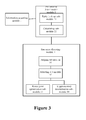
- FIG.3 the structure diagram of the device for allocating uplink shared channel resource described in the embodiments of the present invention.
- the device can be set at a base station and include an information acquiring module 1, a preliminary determination module 2 and a resource allocating module 3, wherein:
- the resource allocating module 3 can further comprise a judging sub-module 31 and a selecting sub-module 32, wherein:
- the selecting sub-module 32 is used for selecting a resource profile meeting the below requirements from the at least one set of resource profile determined when the uplink channel quality indication comprised within the at least one set of resource profile is different from the uplink channel quality indication acquired, the requirements include: the uplink channel quality indication comprised within the resource profile shall be smaller than the uplink channel quality indication acquired; and the uplink transmission power shall be combined with the at least one set of resource profile meeting the above requirements to determine the final resource profile.
- the resource allocating module 3 further can comprise a power joint optimization sub-module 33, for calculating the uplink transmission power of each set of resource profile respectively when there are multiple sets of resource profiles meeting the above requirements and selecting a set of resource profile of minimum uplink transmission power as a final resource profile; and selecting this set of resource profile as the final resource profile when only one set of resource profile meets the above requirements.
- the resource allocating module 3 further can comprise a supplementary determination sub-module 34, for determining a resource number corresponding to the volume of data-to-be-transmitted and the uplink channel quality indication acquired according to the mapping relationship among the volume of data-carried, uplink channel quality indication and resource number when no resource profile in the at least one set of resource profile determined meets the above requirements, and combing the resource number with the uplink channel quality indication acquired into a resource profile as the final resource profile.
- the uplink channel quality indication comprised within the resource profile is greater than the uplink channel quality indication acquired, the resource profile fails to meet the above requirements.
- the preliminary determination module 2 further can comprise a table look-up sub-module 21 and a calculating sub-module 22, wherein:
- the table look-up sub-module 21 can look up the minimum volume of data-carried equal to or greater than the volume of data-to-be-transmitted on the basis of the mapping relationship between the volume of data-carried and resource profile code, and determining at least one resource profile code corresponding to the minimum volume of data-carried as the resource profile code corresponding to the volume of data-to-be-transmitted.
- the embodiment of the present invention further provides a communication system which comprises a terminal and a base station.
- the terminal is used for sending an uplink reference signal to the base station
- the base station can acquire the volume of data-to-be-transmitted and uplink channel quality indication upon the detection and conversion of the reference signal, and then allocate channel resource.
- the base station comprises the device for allocating uplink shared channel resource described in the above embodiments, please refer to the description of the embodiment shown in Fig.3 , which is not described here.
Landscapes
- Engineering & Computer Science (AREA)
- Quality & Reliability (AREA)
- Computer Networks & Wireless Communication (AREA)
- Signal Processing (AREA)
- Mobile Radio Communication Systems (AREA)
Abstract
Description
- This application requires the priority to Chinese patent application, which should be submitted to the Chinese Patent Office on January 14, 2011, the application No.
201110008171.5 - The present invention relates to the field of communication technology, in particular to the method and device for allocating uplink shared channel resource, and communication system.
- In TD-SCDMA (Time Division-Synchronous Code Division Multiple Access), LTE (Long Term Evolution) and other communication systems, the uplink shared channel refers to an uplink transmission channel shareable among several UE (User Equipment).
- The uplink shared channel resource in a communication system is allocated usually by the following methods: first acquiring a channel quality indication, then looking up the mapping table of the channel quality indication and a resource number by use of the channel quality indication, to search a resource number capable of satisfying the volume of data-to-be-transmitted of user as the basis for subsequent allocation of resources.
- Take LTE system as an example. The shared channel resources are all allocated at base station. UE sends an uplink Sounding reference symbol; then the base station detects and converts this reference symbol and characterizes the uplink shared channel quality indication through MCS (Modulation Coding Scheme). After acquiring the channel quality indication, the base station searches a resource profile capable of satisfying the volume of data-to-be-transmitted of user by looking up TB_size table and uses this resource profile as a resource allocation result. Wherein, the TB_size table is the mapping table of the channel quality indication and the resource number, which is shown in Table 1; the resource profile is indicated by MCS level and PRB number; PRB refers to physical resource block (Physical Resource Block), used to describe the actual physical resource allocation; PRB number is the resource number mentioned above.
- For example, Table 1 is TB_size table with LTE standard definition, which lists the tables in a system bandwidth of 1.4MHz. The column ITBS in Table 1 corresponds to the channel quality indication MCS, with the value ranging from 0 to 26; the row NPRB corresponds to the occupied PRB number, with the value ranging from 1 to 110, and ranging from 1 to 6 when the bandwidth is 1.4MHz; the data in the table indicate the data volume tb_size able to carry by the corresponding resource profile (MCS level, PRB number). When the bandwidth is 1.4MHz, for an uplink shared channel, the base station acquires the wideband channel quality indication MCSwideband = 3 by measuring the uplink Sounding reference symbol sent the UE1 and the volume of data-to-be-transmitted of UE1 UE1 data = 200bits. By looking up the fourth row (MCS=3 row) of Table 1, we can know the data volume able to carry by the resource profile (MCS=3, PRB_NUM=4) is 208 bits upon NPRB =4, which is greater than the volume of data-to-be-transmitted of the UE1(200bits), therefore, the resource profile (MCS=3, PRB_NUM=4) can be used as a basis for resource allocation and the specific location of the allocated resource shall be further determined. Finally, the MCS level and the location of the allocated resource are transmitted to UE1 via a control channel; UE1 transmits uplink data in the specified resource location as per designated MCS.
Table 1 TB_size Table [B=1.4MHz] with LTE Standard Definition I TBS N PRB1 2 3 4 5 6 0 16 32 56 88 120 152 1 24 56 88 144 176 208 2 32 72 144 176 208 256 3 40 104 176 208 256 328 4 56 120 208 256 328 408 5 72 144 224 328 424 504 6 328 176 256 392 504 600 7 104 224 328 472 584 712 8 120 256 392 536 680 808 9 136 296 456 616 776 936 10 144 328 504 680 872 1032 11 176 376 584 776 1000 1192 12 208 440 680 904 1128 1352 13 224 488 744 1000 1256 1544 14 256 552 840 1128 1416 1736 15 280 600 904 1224 1544 1800 16 328 632 968 1288 1608 1928 17 336 696 1064 1416 1800 2152 18 376 776 1160 1544 1992 2344 19 408 840 1288 1736 2152 2600 20 440 904 1384 1864 2344 2792 21 488 1000 1480 1992 2472 2984 22 520 1064 1608 2152 2664 3240 23 552 1128 1736 2280 2856 3496 24 584 1192 1800 2408 2984 3624 25 616 1256 1864 2536 3112 3752 26 712 1480 2216 2984 3752 4392 - The above method for allocating uplink channel resource can satisfy the resource allocation of the volume of data-to-be-transmitted of user under normal circumstances, but in some cases, it may cause too much interference, reducing the overall performance of the system.
- The present invention puts forward the method and device for allocating uplink shared channel resource, and communication system, for solving the problem of the overall performance of the communication system being reduced in an existing allocating method.
- For solving the above problem, the present invention discloses the method for allocating uplink shared channel resource, comprising: Acquiring the volume of data-to-be-transmitted and an uplink channel quality indication;
On the basis of the volume of data-to-be-transmitted acquired, determining at least one set of resource profile of the uplink channel quality indication and a resource number;
Judging of whether or not the uplink channel quality indication comprised within the at least one set of resource profile is identical to the uplink channel quality indication acquired, if identical, using a corresponding set of resource profile as a final resource profile; and if different, combining an uplink transmission power with the corresponding set of resource profile to determine the final resource profile. - Preferably, combining an uplink transmission power with the corresponding set of resource profile to determine the final resource profile comprises: selecting a resource profile meeting the following requirements from the at least one set of resource profile determined; the requirements include: the uplink channel quality indication comprised within the resource profile shall be smaller than the uplink channel quality indication acquired; the uplink transmission power shall be combined with the at least one set of resource profile meeting the above requirements to determine the final resource profile.
- Preferably, combining the uplink transmission power with the at least one set of resource profile meeting the above requirements to determine the final resource profile comprises: in case multiple sets of resource profiles meet the above requirements, calculating the uplink transmission power of each set of resource profile respectively, and selecting a set of profile resource of minimum uplink transmission power as a final resource profile; if only one set of resource profile meets the above requirements, using this set of resource profile as the final resource profile.
- Preferably, the method further comprises: if the uplink channel quality indication comprised within the resource profile is greater than the uplink channel quality indication acquired, the resource profile failing to meet the above requirements; when no resource profile in the at least one set of resource profile determined meets the above requirements, determining a resource number corresponding to the volume of the data-to-be-transmitted and the uplink channel quality indication acquired according to the mapping relationship among the volume of data-carried, uplink channel quality indication and resource number, and combing the resource number with the uplink channel quality indication into a resource profile as the final resource profile. Preferably, determining at least one of resource profile of the uplink channel quality indication and a resource number on the basis of the volume of data-to-be-transmitted acquired comprises: determining at least one resource profile code corresponding to the volume of data-to-be-transmitted acquired on the basis of the mapping relationship between the volume of data-carried and resource profile code, each resource profile code corresponding to a set of resource profile of the uplink channel quality indication and resource number; calculating the resource profile of the uplink channel quality indication and resource number corresponding to each resource profile code determined. Preferably, determining at least one resource profile code corresponding to the volume of data-to-be-transmitted acquired on the basis of the mapping relationship between the volume of data-carried and the resource profile code comprises: looking up the minimum volume of data-carried equal to or greater than the volume of data-to-be-transmitted, and determining at least one resource profile code corresponding to the minimum volume of data-carried as the resource profile corresponding to the volume of data-to-be-transmitted. Preferably, calculating the resource profile of the uplink channel quality indication and resource number corresponding to each resource profile code determined comprises: calculating as per the conversion formula of the resource profile code and the resource profile; said conversion formula is: resource profile code=uplink channel quality indication
X weight factor 1 + resource numberX weight factor 2. - The present invention further provides the device for allocating uplink shared channel resource, comprising:
- An information acquiring module, for acquiring the volume of data-to-be-transmitted and an uplink channel quality indication;
- A preliminary determination module, for determining at least one set of resource profile of the uplink channel quality indication and a resource number on the basis of the volume of data-to-be-transmitted acquired;
- A resource allocating module, for judging of whether or not the uplink channel quality indication comprised within the at least one set of resource profile is identical to the uplink channel quality indication acquired, if identical, using a corresponding set of resource profile as a final resource profile; and if different, combining an uplink transmission power with the corresponding set of resource profile to determine the final resource profile. Preferably, the resource allocating module comprises: a judging sub-module, for judging of whether or not the uplink channel quality indication comprised within the at least one set of resource profile determined is identical to the uplink channel quality indication acquired, if identical, using a corresponding set of resource profile as a final resource profile; and if different, triggering a selecting sub-module; a selecting sub-module, for selecting a resource profile meeting the following requirements from the at least one set of resource profile determined when the uplink channel quality indication comprised within the at least one set of resource profile determined is different from the uplink channel quality indication acquired; the requirements include: the uplink channel quality indication comprised within the resource profile shall be smaller than the uplink channel quality indication acquired; the uplink transmission power shall be combined with the at least one set of resource profile meeting the above requirements to determine the final resource profile.
- Preferably, the resource allocating module further comprises: a power joint optimization sub-module, for calculating the uplink transmission power of each set of resource profile respectively when multiple sets of resource profiles meet the above requirements, and selecting a set of resource profile of minimum uplink transmission power as a final resource profile; when only one set of resource profile meets the above requirements, using it as the final resource profile.
- Preferably, if the uplink channel quality indication comprised within the resource profile is greater than the uplink channel quality indication acquired, the resource profile fails to meet the above requirements; and the resource allocating module further comprises: a supplementary determination sub-module, for determining a resource number corresponding to the volume of data-to-be-transmitted and the uplink channel quality indication acquired according to the mapping relationship among the volume of data-carried, uplink channel quality indication and resource number when no resource profile in the at least one set of resource profile determined meets the above requirements, and combining the resource number with the uplink channel quality indication acquired into a resource profile as the final resource profile. Preferably, the preliminary determination module comprises: a table look-up sub-module, for determining at least one resource profile code corresponding to the volume of data-to-be-transmitted acquired on the basis of the mapping relationship between the volume of data-carried and the resource profile code, each resource profile code corresponding to a set of resource profile of the uplink channel quality indication and the resource number; a calculating sub-module, for calculating the resource profile of the uplink channel quality indication and resource number corresponding to each resource profile code determined. Preferably, the table look-up sub-module looks up the minimum volume of data-carried equal to or greater than the volume of data-to-be-transmitted on the basis of the mapping relationship between the volume of data-carried and resource profile code, and determines at least one resource profile code corresponding to the minimum volume of data-carried as the resource profile code corresponding to the volume of data-to-be-transmitted.
- Preferably, the calculating sub-module calculates as per the conversion formula of the resource profile code and the resource profile, the conversion formula is: resource profile code=uplink channel quality indication
X weight factor 1 + resource numberX weight factor 2. - The present invention further provides the communication system, comprising a terminal and a base station; said base station comprises the above device for allocating uplink shared channel resource. Compared with the prior art, the present invention possesses the following advantages:
- In the determination of the resource profile satisfying the volume of data-to-be-transmitted, the present invention not only bases on the channel quality indication that a terminal reports, but also takes into consideration the overall power resource of the system, to combine the uplink transmission power to determine the final resource profile. Under the premise of ensuring QoS (Quality of Service), the present invention allows for minimization of transmission power of each terminal, thus reducing inter-system interference, allowing system performance to be further improved.
-
-
Fig.1 is the flow diagram of the method for allocating uplink shared channel resource described in the embodiments of the present invention; -
Fig.2 is the flow diagram of the method for allocating uplink shared channel resource described in another embodiment of the present invention; -
Fig.3 is the structure diagram of the device for allocating uplink shared channel resource described in the embodiments of the present invention. - To make the above purpose, characteristics and advantages of the present invention clearer and catchier, the technical solution of the present invention is explained in a detailed way with reference to the drawings and specific embodiments.
- On the basis capable of satisfying the volume of data-to-be-transmitted of a user, the present invention puts forward the method and device in consideration of the joint power for resource profile determination to determine the final resource allocation profile (MCS level, PRB number), allowing system performance to be further improved.
- The present invention proposes the following ideas:
- According to the study, there are equal-sized volumes of data-carried tb_size in the TB_size tables shown in Table 1, but the corresponding resource profiles (MCS level, PRB number) are different. In detail, one tb_size value in Table 1 may correspond to multiple sets of different resource profiles (MCS level, PRB number). In other words, in the case of multiple sets of different resource profiles, the volume of the data able to carry tb_size is identical.
- On the basis of the above phenomenon discovered, the tb_size in Table 1 of the present invention is sorted in ascending order and all of the corresponding resource profiles for each different tb_size are summarized to acquire a resource profile summary sheet in the case of 1.4 MHz system bandwidth shown in Table 2.
Table 2 Resource Profile Summary Sheet of Different tb_size tb_size Resource profile code 16 1 24 11 32 2, 21 40 31 56 3, 12, 41 72 22, 51 88 4, 13 104 32, 71 120 5, 42, 81 136 91 144 14, 23, 52, 101 152 6 176 15, 24, 33, 62, 111 208 16, 25, 34, 43, 121 224 53, 72, 131 256 26, 35, 44, 63, 82, 141 280 151 296 92 328 36, 45, 54, 61, 73, 102, 161 336 171 376 112, 181 392 64, 83 408 46, 191 424 55 440 122, 201 456 93 472 74 488 132, 211 504 56, 65, 103 520 221 536 84 552 142, 231 584 75, 113, 241 600 66, 152 616 94, 251 632 162 680 85, 104, 123 696 172 712 76, 261 744 133 776 95, 114, 182 808 86 840 143, 192 872 105 904 124, 153, 202 936 96 968 163 1000 115, 134, 212 1032 106 1064 173, 222 1128 125, 144, 232 1160 183 1192 116, 242 1224 154 1256 135, 252 1288 164, 193 1352 126 1384 203 1416 145, 174 1480 213, 262 1544 136, 155, 184 1608 165, 223 1736 146, 194, 233 1800 156, 175, 243 1864 204, 253 1928 166 1992 185, 214 2152 176, 195, 224 2216 263 2280 234 2344 186, 205 2408 244 2472 215 2536 254 2600 196 2664 225 2792 206 2856 235 2984 216, 245, 264 3112 255 3240 226 3496 236 3624 246 3752 256, 265 4392 266 - The resource profile code in Table 2 indicates the resource allocation profile of the uplink channel quality indication and a resource number, one resource profile code corresponds to one resource profile. It can be seen from Table 2 that, one tb_size value may correspond to one resource profile code, or may correspond to multiple resource profile codes, that is, it may correspond to one resource profile or multiple resource profiles. There are a total of 162 tb_size values in Table 1, 122 tb_size have more than one resource profiles in Table 2 after summarization. That is, different resource profiles of the same tb_size account for 122/162≈77%.
- The present invention puts forward the method for allocating uplink shared channel resource based on Table 2, in which the final resource allocation profile (MCS level, PRB number) can be determined by combining the system power.
- See
Fig.1 , the flow diagram of the method for allocating uplink shared channel resource described in the embodiments of the present invention. - The shared channel resource is allocated at a base station; therefore, the base station executes the following steps:
-
Step 101, acquiring the volume of data-to-be-transmitted and an uplink channel quality indication. - The base station acquires a channel quality indication that terminal reports by measuring the uplink Sounding reference symbol sent by the terminal. The embodiment also characterizes the uplink shared channel quality indication through MCS. Meanwhile, the base station can further acquire the size of the volume of data-to-be-transmitted of the terminal.
-
Step 102, on the basis of the volume of data-to-be-transmitted acquired, determining at least one set of resource profile of the uplink channel quality indication and a resource number. - By looking up Table 2, the base station can determine one or more resource profile codes satisfying the volume of data-to-be-transmitted, due to the conversion relationship between the resource profile code and resource profile (MCS level, PRB number), this conversion relationship is obtainable by mathematical calculation formulas. Therefore, one or more sets of resource profiles (MCS level, PRB number) can be acquired by use of this conversion relationship.
-
Step 103, judging of whether or not the uplink channel quality indication comprised within the at least one set of resource profile is identical to the uplink channel quality indication acquired, if identical, using a corresponding set of resource profile as a final resource profile; and if different, combining an uplink transmission power with the corresponding set of resource profile to determine the final resource profile. - If the MCS in the resource profile determined is identical to the MCS that terminal reports, just meeting the volume of data-to-be-transmitted of the terminal and channel quality requirements, this set (MCS level, PRB number) is selected to allocate to the terminal. If none of the several sets of resource profiles determined in
step 102 is identical to the MCS that terminal reports, then the uplink transmission power can be combined to determine the final resource profile. The specific method can be: for the several sets of resource profiles, calculating the uplink transmission power of each set of resource profile respectively, and then selecting a set of resource profile of minimum uplink transmission power to allocate to the terminal. - The above method mainly refers to the handing of the situation when none of the resource profiles is identical to the MCS that terminal reports. Under the premise of satisfying the volume of data-to-be-transmitted of the terminal and ensuring Qos, as the overall power resource of the system is considered and the resource profile of minimum transmission power is selected to allocate to the terminal, the above methods allow for minimization of transmission power of each terminal, thus reducing inter-system interference, allowing system performance to be further improved.
- Based on the above contents, more detailed descriptions are made by another embodiment shown in
Fig.2 . - See
Fig.2 , the flow diagram of the method for allocating uplink shared channel resource. -
Step 201, acquiring the volume of data-to-be-transmitted and an uplink channel quality indication. - That is, the base station acquires the volume of data-to-be-transmitted from the terminal and the uplink channel quality indication indicated by MCS.
- How to determine at least one set of resource profile of the uplink channel quality indication and a resource number on the basis of the volume of data-to-be-transmitted acquired is described by the following
steps -
Step 202, determining at least one resource profile code corresponding to the volume of data-to-be-transmitted acquired according to the mapping relationship between the volume of data-carried and resource profile code, each resource profile code corresponding to one set of resource profile of the uplink channel quality indication and a resource number. - Table 2 is the mapping relationship table between the volume of data-carried tb_size and resource profile code. In order to maximize the efficient use of system resources, preferably, it is necessary to look up Table 2 according to the volume of data-to-be-transmitted of the user to search the minimum tb_size value capable of satisfying the volume of data-to-be-transmitted of the user first. The table look-up method comprises the following specific steps:
- Looking up the minimum volume of data-carried equal to or greater than the volume of data-to-be-transmitted on the basis of the mapping relationship between the volume of data-carried and resource profile code, and determining at least one resource profile code corresponding to the minimum volume of data-carried as the resource profile code corresponding to the volume of data-to-be-transmitted.
-
Step 203, calculating the resource profile of the uplink channel quality indication and the resource number corresponding to each resource profile code determined. - As mentioned, there is a conversion relationship between the resource profile code and resource profile (MCS level, PRB number); therefore, the resource profile (MCS level, PRB number) can be acquired by the calculation as per this conversion formula.
- The conversion formula is:

- When the
weight factor 2 is equal to 1, the conversion formula is:
- When the system bandwidth B is equal to 1.4MHz, discriminating factorβ_factor=10, the value of the discriminating factor in the case of different system bandwidths is shown in Table 3:
System bandwidth(MHz) Number of resource block Discriminating factor 1.4 6 10 3 15 20 5 25 30 10 50 50 15 75 80 20 100 100 - Table 3 Value Table of Discriminating Factor in Different Bandwidth Based on
formula 1, the formula of calculating MCS level and PRB number is as follows:
- Wherein, └x┘ refers to rounding down;

- Furthermore, if the
weight factor 1 is equal to 1, the above conversion formula is:
- The method of calculating MCS level and PRB number based on formula 4 is similar to that of
formula 2 andformula 3, which is not described here. -
Step 204, judging of whether or not the uplink channel quality indication comprised within the at least one set of resource profile is identical to the uplink channel quality indication acquired; - If identical, using a corresponding set of resource profile as a final resource profile; and if different, continuing the following procedures and combining an uplink transmission power with the corresponding set of resource profile to determine the final resource profile, specifically comprising
steps 205 to 207. -
Step 205, selecting a resource profile meeting the following requirements from the at least one set of resource profile determined. The requirements include: the uplink channel quality indication comprised within the resource profile shall be smaller than the uplink channel quality indication acquired. The uplink channel quality indication acquired is the channel quality indication that terminal reports. - The decoding performance can be guaranteed by the above selection. The higher MCS level requires the higher decoding performance. In case of higher MCS selected, there may be incorrect decoding. Hence, under the premise of ensuring the volume of data-to-be-transmitted, we should try to select a resource profile with MCS level smaller than the channel quality indication that terminal reports.
-
Step 206, combining an uplink transmission power with the at least one set of resource profile meeting the above requirements to determine the final resource profile. - The resource profile with MCS level smaller than the channel quality indication reported shall be further selected in combination with power factors. One or more sets of resource profiles may be selected by
step 205, if multiple sets of resource profiles meet the above requirements, calculate the uplink transmission power of each set of resource profile respectively and select a set of resource profile of minimum uplink transmission power as a final resource profile; if only one set of resource profile meets the above requirements, use this set of resource profile as the final resource profile. - Wherein, the transmission power can be calculated by any one of existing calculation methods, which is not limited in the embodiment of the present invention.
-
Step 207, combining Table 1 to determine the final resource profile if no resource profile meets the above requirements. - If the uplink channel quality indication comprised within the resource profile is greater than the uplink channel quality indication acquired, the resource profile fails to meet the above requirements. When no resource profile in the at least one set of resource profile determined meets the above requirements, determine a resource number corresponding to the volume of data-to-be-transmitted and the uplink channel quality indication acquired by the rules of satisfying the volume of data-to-be-transmitted of the terminal according to the mapping relationship (Table 1) among the volume of data-carried tb_size, uplink channel quality indication MCS and resource number PRB, and combine the resource number with the uplink channel quality indication acquired into a resource profile as the final resource profile. In the following parts, the procedures shown in
Fig.2 are described by three embodiments. - For an uplink shared channel, a base station acquires the wideband channel quality indication MCSwideband =7 by measuring the uplink Sounding reference symbol sent by the UE1 and the volume of data-to-be-transmitted of UE1 UE1 data =140bits. Look up Table 2 to find that the minimum tb_size capable of satisfying the volume of data-to-be-transmitted of the user is equal to 144 bits. Then, look up Table 2 to find that there are a total of 4 resource profile codes, being 14, 23, 52 and 101 respectively, when the tb_size is equal to 144 bits. Calculate the corresponding resource profile through
formula 2 andformula 3 respectively, being (MCS=1, PRB_NUM=4), (MCS=2, PRB_NUM=3), (MCS=5, PRB_NUM=2) and (MCS=10, PRB_NUM=1). First judge of whether or not there is profile with the channel quality indication in the corresponding resource profile identical to the channel quality indication reported. The MCS level of the above resource profile is 1, 2, 5 and 10 respectively, there is no profile identical to the channel quality indication MCS=7 reported, then process secondary selection to pick up the profile with the channel quality indication smaller than the channel quality indication reported in the resource profiles, including (MCS=1, PRB_NUM=4), (MCS=2, PRB_NUM=3) and (MCS=5, PRB_NUM=2). Finally, calculate the uplink transmission power of the above three kinds of resource profiles respectively, the transmission power can be calculated by reference to corresponding LTE physical layer protocol, with the resource profile of minimum transmission power selected as the final resource profile for output. - For an uplink shared channel, a base station acquires the wideband channel quality indication MCSwideband = 8 by measuring the uplink Sounding reference symbol sent by the UE1, and the volume of data-to-be-transmitted of the UE1 UE1data =110bits. Look up Table 2 to find the minimum tb_size capable of satisfying the volume of data-to-be-transmitted of the user is equal to 120 bits. Then look up Table to find that there are a total of 3 resource profile codes, being 5, 42 and 81 respectively, when the tb_size is equal to 120 bits. Calculate corresponding resource profiles by use of
formula 2 andformula 3 respectively, being (MCS=0, PRB_NUM=5), (MCS=4, PRB_NUM=2) and (MCS=8, PRB_NUM=1). First judge of whether or not there is profile with the channel quality indication identical to the channel quality indication reported in the corresponding resource profile. MCS level of the above resource profile is respectively 0, 4 and 8, there is profile (MCS=8, PRB_NUM=1) identical to the channel quality indication MCS=8 reported, output the resource profile as the final resource profile. - For an uplink shared channel, a base station acquires the wideband channel quality indication MCSwideband =4 by measuring the uplink Sounding reference symbol sent by the UE1, and the volume of data-to-be-transmitted of the UE1 UE1 data =390bits. Look up Table 2 to find that the minimum tb_size capable of satisfying the volume of data-to-be-transmitted of the user is equal to 392 bits. Then, look up Table 2 to find that there are a total of 2 resource profile codes, being 64 and 83 respectively, when the tb_size is equal to 392 bits. Calculate the corresponding resource profile by use of
formula 2 andformula 3 respectively, being (MCS=6, PRB_NUM=4) and (MCS=8, PRB_NUM=3). First judge of whether or not there is profile with the channel quality indication identical to the channel quality indication reported in the corresponding resource profile. The MCS level of the above resource profile is 6 and 8 respectively, there is no resource profile identical to the channel quality indication MCS=4 reported. The second step is to search the resource profile with the MCS level smaller than the channel quality indication reported from the resource profiles, exit as no resource profile meeting the requirements is found, by looking up the fifth row (MCS=4 row) in Table 1 at MCS=4, it can be known that the volume of the data able to carry by the resource profile (MCS=4, PRB_NUM=6) is 408 bits in case of NPRB = 6, which is greater than the volume of data-to-be-transmitted of the UE1. The resource profile (MCS=4, PRB_NUM=6) is output as the final resource profile. From the above, the invention is easy to realize, which only requires slightly adding storage space of a few tables on the basis of the original method, with the increase in computation complexity negligible. Based on the above embodiment methods, the present invention further provides the corresponding device and system embodiments, specifically shown as follows. - See
Fig.3 , the structure diagram of the device for allocating uplink shared channel resource described in the embodiments of the present invention. - The device can be set at a base station and include an
information acquiring module 1, apreliminary determination module 2 and aresource allocating module 3, wherein: - The
information obtaining module 1 is used for acquiring the volume of data-to-be-transmitted and an uplink channel quality indication; - The
preliminary determination module 2 is used for determining at least one set of resource profile of the uplink channel quality indication and a resource number on the basis of the volume of data-to-be-transmitted acquired; - The
resource allocating module 3 is used for judging of whether or not the uplink channel quality indication comprised within the at least one set of resource profile is identical to the uplink channel quality indication acquired, if identical, using a corresponding set of resource profile as a final resource profile; and if different, combining an uplink transmission power with the corresponding set of resource profile to determine the final resource profile. - Preferably, in order to ensure decoding performance, the
resource allocating module 3 can further comprise a judgingsub-module 31 and a selectingsub-module 32, wherein: - The judging
sub-module 31 is used for judging of whether or not the uplink channel quality indication comprised within the at least one set of resource profile is identical to the uplink channel quality indication acquired, if identical, using a corresponding set of resource profile as a final resource profile; and if different, triggering the selectingsub-module 32. - The selecting
sub-module 32 is used for selecting a resource profile meeting the below requirements from the at least one set of resource profile determined when the uplink channel quality indication comprised within the at least one set of resource profile is different from the uplink channel quality indication acquired, the requirements include: the uplink channel quality indication comprised within the resource profile shall be smaller than the uplink channel quality indication acquired; and the uplink transmission power shall be combined with the at least one set of resource profile meeting the above requirements to determine the final resource profile. - Based on the selecting
sub-module 32, theresource allocating module 3 further can comprise a powerjoint optimization sub-module 33, for calculating the uplink transmission power of each set of resource profile respectively when there are multiple sets of resource profiles meeting the above requirements and selecting a set of resource profile of minimum uplink transmission power as a final resource profile; and selecting this set of resource profile as the final resource profile when only one set of resource profile meets the above requirements. - If no resource profile meets the above requirements, the
resource allocating module 3 further can comprise a supplementary determination sub-module 34, for determining a resource number corresponding to the volume of data-to-be-transmitted and the uplink channel quality indication acquired according to the mapping relationship among the volume of data-carried, uplink channel quality indication and resource number when no resource profile in the at least one set of resource profile determined meets the above requirements, and combing the resource number with the uplink channel quality indication acquired into a resource profile as the final resource profile. Wherein, if the uplink channel quality indication comprised within the resource profile is greater than the uplink channel quality indication acquired, the resource profile fails to meet the above requirements. - To be specific, the
preliminary determination module 2 further can comprise a table look-up sub-module 21 and a calculatingsub-module 22, wherein: - The table look-up sub-module 21 is used for determining at least one resource profile code corresponding to the volume of data-to-be-transmitted acquired on the basis of the mapping relationship between the volume of data-carried and resource profile code, each resource profile code corresponding to a set of resource profile of the uplink channel quality indication and resource number;
- The calculating
sub-module 22 is used for calculating the resource profile of the uplink channel quality indication and resource number corresponding to each resource profile code determined. - The table look-up sub-module 21 can look up the minimum volume of data-carried equal to or greater than the volume of data-to-be-transmitted on the basis of the mapping relationship between the volume of data-carried and resource profile code, and determining at least one resource profile code corresponding to the minimum volume of data-carried as the resource profile code corresponding to the volume of data-to-be-transmitted.
- The calculating
sub-module 22 can conduct calculation based on the conversion formula of the resource profile code and resource profile, said conversion formula is:
- The above-mentioned device embodiment is relatively simply described as it is similar to the method embodiment, for related information, please refer to part description of method embodiment.
- The embodiment of the present invention further provides a communication system which comprises a terminal and a base station. The terminal is used for sending an uplink reference signal to the base station, the base station can acquire the volume of data-to-be-transmitted and uplink channel quality indication upon the detection and conversion of the reference signal, and then allocate channel resource. Wherein, the base station comprises the device for allocating uplink shared channel resource described in the above embodiments, please refer to the description of the embodiment shown in
Fig.3 , which is not described here. - All embodiments in the present invention are described in a progressive manner, each of embodiments focuses on the part different from other embodiments, please refer to each other for the same or similar parts among embodiments.
- In the above part, the method and device for allocating uplink shared channel resource and communication system provided in the present invention are introduced in detail. Specific cases are used to expound the principle and implementation modes of the present invention. The above embodiments are described only for facilitating the comprehension of method of the present invention as well as core idea thereof; meanwhile, for general technical personnel in this field, some changes on the specific implementation ways and scope of application can be done based on the idea of the present invention, which shall not be construed as a limit to the present invention in conclusion.
Claims (15)
- A method for allocating uplink shared channel resource, wherein, comprising:acquiring the volume of data-to-be-transmitted and an uplink channel quality indication;on the basis of the volume of data-to-be-transmitted acquired, determining at least one set of resource profile of the uplink channel quality indication and a resource number;judging of whether or not the uplink channel quality indication comprised within the at least one set of resource profile is identical to the uplink channel quality indication acquired, if identical, using a corresponding set of resource profile as a final resource profile; and if different, combining an uplink transmission power with the corresponding set of resource profile to determine the final resource profile.
- The method according to claim 1, wherein, combining an uplink transmission power with the corresponding set of resource profile to determine the final resource profile, comprises:selecting resource profiles meeting the below requirements from the at least one set of resource profile determined; said requirements include:the uplink channel quality indication comprised within the resource profile shall be smaller than the uplink channel quality indication acquired;the uplink transmission power shall be combined with the at least one set of resource profile meeting the above requirements to determine the final resource profile.
- The method according to claim 2, wherein, combining an uplink transmission power with the at least one set of resource profile meeting the above requirements to determine the final resource profile, comprises:if multiple sets of resource profiles meet the above requirements, calculating the uplink transmission power of each set of resource profile respectively, and selecting a set of resource profile of minimum uplink transmission power as a final resource profile;if only one set of resource profile meets the above requirements, using this set of resource profile as the final resource profile.
- The method according to claim 2, wherein, combining an uplink transmission power with corresponding set of resource profile to determine the final resource profile, further comprises:if the uplink channel quality indication comprised within the resource profile is greater than the uplink channel quality indication acquired, the resource profile failing to meet the above requirements;when no resource profile in the at least one set of resource profile determined meets the above requirements, determining a resource number corresponding to the volume of data-to-be-transmitted and the uplink channel quality indication acquired according to the mapping relationship among the volume of data-carried, uplink channel quality indication and resource number, and combing the resource number with the uplink channel quality indication acquired into a resource profile as the final resource profile.
- The method according to claim 1, wherein, determining at least one set of resource profile of the uplink channel quality indication and a resource number on the basis of the volume of data-to-be-transmitted acquired, comprises:determining at least one resource profile code corresponding to the volume of data-to-be-transmitted acquired according to the mapping relationship between the volume of data-carried and resource profile code, each resource profile code corresponding to a set of resource profile of the uplink channel quality indication and the resource number;calculating the resource profile of the uplink channel quality indication andresource number corresponding to each resource profile code determined.
- The method according to claim 5, wherein, determining at least one resource profile code corresponding to the volume of data-to-be-transmitted acquired according to the mapping relationship between the volume of data-carried and resource profile code, comprises:looking up minimum volume of data-carried equal to or greater than the volume of data-to-be-transmitted on the basis of the mapping relationship between the volume of data-carried and resource profile code, anddetermining at least one resource profile code corresponding to the minimum volume of data-carried as a resource profile code corresponding to the volume of data-to-be-transmitted.
- The method according to claim 5, wherein, calculating the resource profile of uplink channel quality indication and resource number corresponding to each resource profile code determined, comprises:calculating as per the conversion formula of resource profile code andresource profile; the conversion formula is:

- A device for allocating uplink shared channel resource, wherein, comprising:an information acquiring module, is used to acquire the volume of data-to-be-transmitted and an uplink channel quality indication;a preliminary determination module, is used to determine at least one set of resource profile of the uplink channel quality indication and a resource number on the basis of the volume of data-to-be-transmitted acquired;a resource allocating module, is used to judge of whether or not the uplink channel quality indication comprised within the at least one set of resource profile is identical to the uplink channel quality indication acquired, if identical, use a corresponding set of resource profile as a final resource profile; and if different, combine an uplink transmission power with the corresponding set of resource profile to determine the final resource profile.
- The device according to claim 8, wherein, the resource allocating module comprises:a judging sub-module, is use to judge of whether or not the uplink channel quality indication comprised within the at least one set of resource profile determined is identical to the uplink channel quality indication acquired, if identical, use a corresponding set of resource profile as a final resource profile; and if different, trigger a selecting sub-module;a selecting sub-module, is used to select a resource profile meeting the following requirements from the at least one set of resource profile determined when the uplink channel quality indication comprised within the at least one set of resource profile determined is different from the uplink channel quality indication acquired, the requirements include: the uplink channel quality indication comprised within the resource profile shall be smaller than the uplink channel quality indication acquired; the uplink transmission power shall be combined with the at least one set of resource profile meeting the above requirements to determine the final resource profile.
- The device according to claim 9, wherein, the resource allocating module further comprises:a power joint optimization sub-module, is used to calculate the uplink transmission power of each set of resource profile respectively when multiple sets of resource profiles meet the above requirements, andselect a set of resource profile of the minimum uplink transmission power as a final resource profile; when only one set of resource profile meets the above requirements, use it as the final resource profile.
- The device according to claim 8, wherein:if the uplink channel quality indication comprised within the resource profile is greater than the uplink channel quality indication acquired,the resource profile fails to meet the above requirements; and the resource allocating module further comprises:a supplementary determination sub-module, is used to determine a resource number corresponding to the volume of data-to-be-transmitted and the uplink channel quality indication acquired according to the mapping relationship among the volume of the data-carried, uplink channel quality indication and resource number when no resource profile in the at least one set of resource profile determined meets the above requirements, and combine the resource number with the uplink channel quality indication acquired into a resource profile as the final resource profile.
- The device according to claim 8, wherein, the preliminary determination module comprises:a table look-up sub-module, is used to determine at least one resource profile code corresponding to the volume of data-to-be-transmitted acquired on the basis of the mapping relationship between the volume of data-carried and the resource profile code, each resource profile code corresponding to a set of resource profile of the uplink channel quality indication and the resource number;a calculating sub-module, is used to calculate the resource profile of the uplink channel quality indication and resource number corresponding to each resource profile code determined.
- The device according to claim 12, wherein:the table look-up sub-module looks up the minimum volume of data-carried equal to or greater than the volume of data-to-be-transmitted on the basis of the mapping relationship between the volume of data-carried and resource profile code, and determines the at least one resource profile code corresponding to the minimum volume of data-carried as the resource profile code corresponding to the volume of data-to-be-transmitted.
- The device according to claim 12, wherein:the calculating sub-module calculates as per the conversion formula of the resource profile code and the resource profile, the conversion formula is:

- A communication system, comprising a terminal and a base station, wherein, the base station comprises the device for allocating uplink shared channel resource described in any one of claims 8 to 14.
Applications Claiming Priority (2)
| Application Number | Priority Date | Filing Date | Title |
|---|---|---|---|
| CN2011100081715A CN102056306B (en) | 2011-01-14 | 2011-01-14 | Method and device for allocating uplink shared channel resources and communication system |
| PCT/CN2012/070238 WO2012095004A1 (en) | 2011-01-14 | 2012-01-11 | Method and device for allocating uplink shared channel resource, and communication system |
Publications (3)
| Publication Number | Publication Date |
|---|---|
| EP2685770A1 true EP2685770A1 (en) | 2014-01-15 |
| EP2685770A4 EP2685770A4 (en) | 2014-10-01 |
| EP2685770B1 EP2685770B1 (en) | 2016-08-31 |
Family
ID=43960082
Family Applications (1)
| Application Number | Title | Priority Date | Filing Date |
|---|---|---|---|
| EP12734025.5A Active EP2685770B1 (en) | 2011-01-14 | 2012-01-11 | Method and device for allocating uplink shared channel resource, and communication system |
Country Status (4)
| Country | Link |
|---|---|
| US (1) | US9980249B2 (en) |
| EP (1) | EP2685770B1 (en) |
| CN (1) | CN102056306B (en) |
| WO (1) | WO2012095004A1 (en) |
Families Citing this family (9)
| Publication number | Priority date | Publication date | Assignee | Title |
|---|---|---|---|---|
| CN102056306B (en) * | 2011-01-14 | 2013-10-16 | 大唐移动通信设备有限公司 | Method and device for allocating uplink shared channel resources and communication system |
| MX359492B (en) * | 2013-10-31 | 2018-09-07 | Huawei Tech Co Ltd | Method and device for information announcement and reporting and data reception. |
| CN109039569A (en) * | 2013-10-31 | 2018-12-18 | 华为技术有限公司 | Information notice reports and data receiver method, equipment |
| US20160088639A1 (en) * | 2014-09-22 | 2016-03-24 | Qualcomm Incorporated | Link adaptation for coordinated scheduling |
| CN110267311B (en) | 2016-01-27 | 2020-06-19 | 华为技术有限公司 | Communication method, network side equipment and terminal |
| CN108633011A (en) * | 2017-03-21 | 2018-10-09 | 大唐移动通信设备有限公司 | A kind of method, base station and the terminal of pre-scheduling terminal |
| CN111294151B (en) * | 2019-07-05 | 2023-07-25 | 展讯通信(上海)有限公司 | Channel quality reporting method, base station, user equipment, and readable storage medium |
| US11336392B2 (en) * | 2019-07-12 | 2022-05-17 | At&T Intellectual Property I, L.P. | Enhancing the robustness of uplink transmission |
| CN113835900B (en) * | 2021-11-26 | 2022-02-22 | 山东产研鲲云人工智能研究院有限公司 | Neural network computing method, device, equipment and computer readable storage medium |
Family Cites Families (37)
| Publication number | Priority date | Publication date | Assignee | Title |
|---|---|---|---|---|
| CN1852073B (en) * | 2005-11-21 | 2010-05-05 | 华为技术有限公司 | A method for allocating resources in downlink packet data transmission |
| JP4589250B2 (en) * | 2006-02-21 | 2010-12-01 | 富士通株式会社 | Power control apparatus in wireless communication system |
| US10020858B2 (en) * | 2006-03-03 | 2018-07-10 | Nec Corporation | Multi-input multi-output communication system, transmitter, and method of assigning resources therein |
| WO2007129941A1 (en) * | 2006-05-04 | 2007-11-15 | Telefonaktiebolaget Lm Ericsson (Publ) | Method, apparatus and computer readable medium for obtaining efficient downlink power transmission |
| JP4601596B2 (en) * | 2006-10-03 | 2010-12-22 | 株式会社エヌ・ティ・ティ・ドコモ | Base station apparatus and method |
| CN101179837A (en) * | 2006-11-08 | 2008-05-14 | 中兴通讯股份有限公司 | Decoding device for enhanced uplink physical channel in time division synchronous code division multiple access system |
| CN101675698B (en) * | 2007-03-01 | 2013-06-05 | 株式会社Ntt都科摩 | Base station device and communication control method |
| KR20090118074A (en) * | 2007-03-01 | 2009-11-17 | 가부시키가이샤 엔티티 도코모 | Base station equipment and communication control method |
| CN103974399B (en) * | 2007-03-07 | 2019-01-29 | 交互数字技术公司 | Method and WTRU for controlling transmit power of a WTRU |
| US8229451B2 (en) * | 2007-05-02 | 2012-07-24 | Telefonaktiebolaget Lm Ericsson (Publ) | Method and arrangement for managing inter-cell interference in a communications network |
| KR101405974B1 (en) * | 2007-08-16 | 2014-06-27 | 엘지전자 주식회사 | Methods for transmitting codewords in multiple input multiple output system |
| KR100932555B1 (en) * | 2007-12-03 | 2009-12-17 | 한국전자통신연구원 | Resource Allocation Method of Mobile Communication System |
| EP2242303B1 (en) * | 2008-02-03 | 2013-01-09 | LG Electronics Inc. | Method for transmitting cqi in wireless communication system |
| CN101978630B (en) * | 2008-03-31 | 2013-06-12 | 富士通株式会社 | Receiving apparatus, transmitting apparatus, reception method, and transmission method |
| KR101228052B1 (en) * | 2008-06-20 | 2013-01-31 | 닛본 덴끼 가부시끼가이샤 | Resource allocation method, identification method, radio communication system, base station, mobile station, and recording medium |
| US8830926B2 (en) * | 2008-10-27 | 2014-09-09 | Nokia Siemens Networks Oy | Method for network co-ordination in a mobile communications system and apparatus thereof |
| US8750883B2 (en) * | 2008-11-12 | 2014-06-10 | Industrial Technology Research Institute | Communication network method and apparatus including macro base station and femto base station |
| US8582513B2 (en) * | 2008-12-12 | 2013-11-12 | Electronics And Telecommunications Research Institute | Apparatus and method for controlling inter-cell interference |
| JP5556820B2 (en) * | 2008-12-22 | 2014-07-23 | 日本電気株式会社 | Communication system, terminal, base station, transmission power determination method, and program |
| WO2010074216A1 (en) * | 2008-12-25 | 2010-07-01 | 日本電気株式会社 | Wireless base station, method of control of wireless communication, and program |
| US8439842B2 (en) * | 2009-01-29 | 2013-05-14 | General Electric Company | Method and device for controlling transmission power of an active transducer |
| US8284732B2 (en) * | 2009-02-03 | 2012-10-09 | Motorola Mobility Llc | Method and apparatus for transport block signaling in a wireless communication system |
| US8660071B2 (en) * | 2009-03-19 | 2014-02-25 | Qualcomm Incorporated | Adaptive resource partitioning in a wireless communication network |
| US8537750B2 (en) * | 2009-06-02 | 2013-09-17 | Futurewei Technologies, Inc. | System and method for transport block size design for multiple-input, multiple-output (MIMO) in a wireless communications system |
| WO2011010863A2 (en) * | 2009-07-21 | 2011-01-27 | Lg Electronics Inc. | Apparatus and method for transmitting channel state information in a wireless communication system |
| US8599715B2 (en) * | 2009-07-30 | 2013-12-03 | Lg Electronics Inc. | Apparatus and method for transmitting channel state information in a mobile communication system |
| EP2282575A1 (en) * | 2009-08-04 | 2011-02-09 | Panasonic Corporation | Channel quality reporting in a mobile communications system |
| US9055576B2 (en) * | 2009-10-08 | 2015-06-09 | Qualcomm Incorporated | Uplink resource allocation for LTE advanced |
| CN102687568B (en) * | 2009-12-29 | 2015-04-01 | 意大利电信股份公司 | Adaptive scheduling data transmission based on the transmission power and the number of physical resource blocks |
| WO2011084020A2 (en) * | 2010-01-08 | 2011-07-14 | 엘지전자 주식회사 | Method and apparatus for transmitting uplink control information in wireless communication system for supporting multi-carriers |
| US20120282889A1 (en) * | 2010-01-12 | 2012-11-08 | Sumitomo Electric Industries, Ltd | Base station device |
| CN104618077B (en) * | 2010-03-29 | 2018-04-17 | Lg电子株式会社 | Control information is transmitted to support the effective ways of uplink multi-antenna transmission and device |
| KR101867820B1 (en) * | 2010-09-16 | 2018-06-18 | 엘지전자 주식회사 | Method and device for transmitting control information in wireless communication system |
| US8913515B2 (en) * | 2010-12-15 | 2014-12-16 | Mediatek Singapore Pte. Ltd. | Measuring and improving multiuser downlink reception quality in wireless local area networks |
| CN102056306B (en) * | 2011-01-14 | 2013-10-16 | 大唐移动通信设备有限公司 | Method and device for allocating uplink shared channel resources and communication system |
| US8861494B2 (en) * | 2011-06-03 | 2014-10-14 | Alcatel Lucent | Self-organizing communication networks |
| US8805986B2 (en) * | 2011-10-31 | 2014-08-12 | Sap Ag | Application scope adjustment based on resource consumption |
-
2011
- 2011-01-14 CN CN2011100081715A patent/CN102056306B/en active Active
-
2012
- 2012-01-11 EP EP12734025.5A patent/EP2685770B1/en active Active
- 2012-01-11 WO PCT/CN2012/070238 patent/WO2012095004A1/en not_active Ceased
- 2012-01-11 US US13/979,446 patent/US9980249B2/en active Active
Also Published As
| Publication number | Publication date |
|---|---|
| US9980249B2 (en) | 2018-05-22 |
| US20130294280A1 (en) | 2013-11-07 |
| CN102056306A (en) | 2011-05-11 |
| EP2685770B1 (en) | 2016-08-31 |
| CN102056306B (en) | 2013-10-16 |
| EP2685770A4 (en) | 2014-10-01 |
| WO2012095004A1 (en) | 2012-07-19 |
Similar Documents
| Publication | Publication Date | Title |
|---|---|---|
| EP2685770B1 (en) | Method and device for allocating uplink shared channel resource, and communication system | |
| US11032814B2 (en) | Decoding control information received over a control channel | |
| EP2217031B1 (en) | Efficient signaling over access channel | |
| RU2599729C1 (en) | Method of allocating the number of candidates for channel control and the number of times of blind detection, base station and user equipment | |
| US8724575B2 (en) | Method and device for allocating control channel element resources | |
| EP2941076B1 (en) | Method and device for obtaining corresponding relationship between random access parameter and resource | |
| EP2337414A1 (en) | Method and apparatus for resource distribution between multiple users | |
| EP3142445B1 (en) | Data transmission method, device and system | |
| US12363681B2 (en) | Data transmission method, data transmission device, non-transitory computer readable medium, and chip | |
| CN109586888B (en) | Method and device for allocating control channel candidates | |
| EP2819337A1 (en) | Method and device for hybrid automatic repeat request of adaptive frame structure | |
| WO2017167014A1 (en) | Data transmission method and device, and storage medium | |
| EP3383095B1 (en) | Multi-user access method and device | |
| EP3306997B1 (en) | Data packet transmission method and device | |
| JP2023501623A (en) | Data transmission method, data transmission device, non-transitory computer readable medium and chip | |
| EP3758430A1 (en) | Transmission method and device, computer readable storage medium | |
| KR20120025103A (en) | Method and apparatus for scheduling in wireless communication system using dual cell | |
| EP2723131B1 (en) | Information transmission method, information transmission apparatus, and base station | |
| EP4447357A1 (en) | Data transmission method and apparatus | |
| EP3606207B1 (en) | Resource allocation method and apparatus | |
| EP4093113B1 (en) | Communication method and communication device | |
| EP2676383B1 (en) | Method and apparatus for performing initial ranging for machine to machine communication service in a mobile communication system | |
| CN107801245B (en) | Method and system for sending downlink data feedback information | |
| RU2372749C2 (en) | Access channel effective indication | |
| EP4451714A1 (en) | Information sending method and communication apparatus |
Legal Events
| Date | Code | Title | Description |
|---|---|---|---|
| PUAI | Public reference made under article 153(3) epc to a published international application that has entered the european phase |
Free format text: ORIGINAL CODE: 0009012 |
|
| 17P | Request for examination filed |
Effective date: 20131120 |
|
| AK | Designated contracting states |
Kind code of ref document: A1 Designated state(s): AL AT BE BG CH CY CZ DE DK EE ES FI FR GB GR HR HU IE IS IT LI LT LU LV MC MK MT NL NO PL PT RO RS SE SI SK SM TR |
|
| DAX | Request for extension of the european patent (deleted) | ||
| A4 | Supplementary search report drawn up and despatched |
Effective date: 20140829 |
|
| RIC1 | Information provided on ipc code assigned before grant |
Ipc: H04W 72/04 20090101AFI20140825BHEP |
|
| 17Q | First examination report despatched |
Effective date: 20150728 |
|
| GRAP | Despatch of communication of intention to grant a patent |
Free format text: ORIGINAL CODE: EPIDOSNIGR1 |
|
| INTG | Intention to grant announced |
Effective date: 20160330 |
|
| GRAS | Grant fee paid |
Free format text: ORIGINAL CODE: EPIDOSNIGR3 |
|
| GRAA | (expected) grant |
Free format text: ORIGINAL CODE: 0009210 |
|
| AK | Designated contracting states |
Kind code of ref document: B1 Designated state(s): AL AT BE BG CH CY CZ DE DK EE ES FI FR GB GR HR HU IE IS IT LI LT LU LV MC MK MT NL NO PL PT RO RS SE SI SK SM TR |
|
| REG | Reference to a national code |
Ref country code: CH Ref legal event code: EP Ref country code: GB Ref legal event code: FG4D |
|
| REG | Reference to a national code |
Ref country code: IE Ref legal event code: FG4D |
|
| REG | Reference to a national code |
Ref country code: DE Ref legal event code: R096 Ref document number: 602012022408 Country of ref document: DE |
|
| REG | Reference to a national code |
Ref country code: AT Ref legal event code: REF Ref document number: 825922 Country of ref document: AT Kind code of ref document: T Effective date: 20161015 |
|
| REG | Reference to a national code |
Ref country code: LT Ref legal event code: MG4D |
|
| REG | Reference to a national code |
Ref country code: NL Ref legal event code: MP Effective date: 20160831 |
|
| REG | Reference to a national code |
Ref country code: AT Ref legal event code: MK05 Ref document number: 825922 Country of ref document: AT Kind code of ref document: T Effective date: 20160831 |
|
| REG | Reference to a national code |
Ref country code: FR Ref legal event code: PLFP Year of fee payment: 6 |
|
| PG25 | Lapsed in a contracting state [announced via postgrant information from national office to epo] |
Ref country code: NO Free format text: LAPSE BECAUSE OF FAILURE TO SUBMIT A TRANSLATION OF THE DESCRIPTION OR TO PAY THE FEE WITHIN THE PRESCRIBED TIME-LIMIT Effective date: 20161130 Ref country code: RS Free format text: LAPSE BECAUSE OF FAILURE TO SUBMIT A TRANSLATION OF THE DESCRIPTION OR TO PAY THE FEE WITHIN THE PRESCRIBED TIME-LIMIT Effective date: 20160831 Ref country code: FI Free format text: LAPSE BECAUSE OF FAILURE TO SUBMIT A TRANSLATION OF THE DESCRIPTION OR TO PAY THE FEE WITHIN THE PRESCRIBED TIME-LIMIT Effective date: 20160831 Ref country code: LT Free format text: LAPSE BECAUSE OF FAILURE TO SUBMIT A TRANSLATION OF THE DESCRIPTION OR TO PAY THE FEE WITHIN THE PRESCRIBED TIME-LIMIT Effective date: 20160831 Ref country code: HR Free format text: LAPSE BECAUSE OF FAILURE TO SUBMIT A TRANSLATION OF THE DESCRIPTION OR TO PAY THE FEE WITHIN THE PRESCRIBED TIME-LIMIT Effective date: 20160831 |
|
| PG25 | Lapsed in a contracting state [announced via postgrant information from national office to epo] |
Ref country code: NL Free format text: LAPSE BECAUSE OF FAILURE TO SUBMIT A TRANSLATION OF THE DESCRIPTION OR TO PAY THE FEE WITHIN THE PRESCRIBED TIME-LIMIT Effective date: 20160831 Ref country code: AT Free format text: LAPSE BECAUSE OF FAILURE TO SUBMIT A TRANSLATION OF THE DESCRIPTION OR TO PAY THE FEE WITHIN THE PRESCRIBED TIME-LIMIT Effective date: 20160831 Ref country code: GR Free format text: LAPSE BECAUSE OF FAILURE TO SUBMIT A TRANSLATION OF THE DESCRIPTION OR TO PAY THE FEE WITHIN THE PRESCRIBED TIME-LIMIT Effective date: 20161201 Ref country code: SE Free format text: LAPSE BECAUSE OF FAILURE TO SUBMIT A TRANSLATION OF THE DESCRIPTION OR TO PAY THE FEE WITHIN THE PRESCRIBED TIME-LIMIT Effective date: 20160831 Ref country code: LV Free format text: LAPSE BECAUSE OF FAILURE TO SUBMIT A TRANSLATION OF THE DESCRIPTION OR TO PAY THE FEE WITHIN THE PRESCRIBED TIME-LIMIT Effective date: 20160831 Ref country code: ES Free format text: LAPSE BECAUSE OF FAILURE TO SUBMIT A TRANSLATION OF THE DESCRIPTION OR TO PAY THE FEE WITHIN THE PRESCRIBED TIME-LIMIT Effective date: 20160831 |
|
| PG25 | Lapsed in a contracting state [announced via postgrant information from national office to epo] |
Ref country code: EE Free format text: LAPSE BECAUSE OF FAILURE TO SUBMIT A TRANSLATION OF THE DESCRIPTION OR TO PAY THE FEE WITHIN THE PRESCRIBED TIME-LIMIT Effective date: 20160831 Ref country code: RO Free format text: LAPSE BECAUSE OF FAILURE TO SUBMIT A TRANSLATION OF THE DESCRIPTION OR TO PAY THE FEE WITHIN THE PRESCRIBED TIME-LIMIT Effective date: 20160831 |
|
| PG25 | Lapsed in a contracting state [announced via postgrant information from national office to epo] |
Ref country code: SK Free format text: LAPSE BECAUSE OF FAILURE TO SUBMIT A TRANSLATION OF THE DESCRIPTION OR TO PAY THE FEE WITHIN THE PRESCRIBED TIME-LIMIT Effective date: 20160831 Ref country code: CZ Free format text: LAPSE BECAUSE OF FAILURE TO SUBMIT A TRANSLATION OF THE DESCRIPTION OR TO PAY THE FEE WITHIN THE PRESCRIBED TIME-LIMIT Effective date: 20160831 Ref country code: BE Free format text: LAPSE BECAUSE OF FAILURE TO SUBMIT A TRANSLATION OF THE DESCRIPTION OR TO PAY THE FEE WITHIN THE PRESCRIBED TIME-LIMIT Effective date: 20160831 Ref country code: SM Free format text: LAPSE BECAUSE OF FAILURE TO SUBMIT A TRANSLATION OF THE DESCRIPTION OR TO PAY THE FEE WITHIN THE PRESCRIBED TIME-LIMIT Effective date: 20160831 Ref country code: DK Free format text: LAPSE BECAUSE OF FAILURE TO SUBMIT A TRANSLATION OF THE DESCRIPTION OR TO PAY THE FEE WITHIN THE PRESCRIBED TIME-LIMIT Effective date: 20160831 Ref country code: PT Free format text: LAPSE BECAUSE OF FAILURE TO SUBMIT A TRANSLATION OF THE DESCRIPTION OR TO PAY THE FEE WITHIN THE PRESCRIBED TIME-LIMIT Effective date: 20170102 Ref country code: BG Free format text: LAPSE BECAUSE OF FAILURE TO SUBMIT A TRANSLATION OF THE DESCRIPTION OR TO PAY THE FEE WITHIN THE PRESCRIBED TIME-LIMIT Effective date: 20161130 Ref country code: PL Free format text: LAPSE BECAUSE OF FAILURE TO SUBMIT A TRANSLATION OF THE DESCRIPTION OR TO PAY THE FEE WITHIN THE PRESCRIBED TIME-LIMIT Effective date: 20160831 |
|
| REG | Reference to a national code |
Ref country code: DE Ref legal event code: R097 Ref document number: 602012022408 Country of ref document: DE |
|
| PG25 | Lapsed in a contracting state [announced via postgrant information from national office to epo] |
Ref country code: IT Free format text: LAPSE BECAUSE OF FAILURE TO SUBMIT A TRANSLATION OF THE DESCRIPTION OR TO PAY THE FEE WITHIN THE PRESCRIBED TIME-LIMIT Effective date: 20160831 |
|
| PLBE | No opposition filed within time limit |
Free format text: ORIGINAL CODE: 0009261 |
|
| STAA | Information on the status of an ep patent application or granted ep patent |
Free format text: STATUS: NO OPPOSITION FILED WITHIN TIME LIMIT |
|
| 26N | No opposition filed |
Effective date: 20170601 |
|
| PG25 | Lapsed in a contracting state [announced via postgrant information from national office to epo] |
Ref country code: SI Free format text: LAPSE BECAUSE OF FAILURE TO SUBMIT A TRANSLATION OF THE DESCRIPTION OR TO PAY THE FEE WITHIN THE PRESCRIBED TIME-LIMIT Effective date: 20160831 |
|
| REG | Reference to a national code |
Ref country code: CH Ref legal event code: PL |
|
| PG25 | Lapsed in a contracting state [announced via postgrant information from national office to epo] |
Ref country code: MC Free format text: LAPSE BECAUSE OF FAILURE TO SUBMIT A TRANSLATION OF THE DESCRIPTION OR TO PAY THE FEE WITHIN THE PRESCRIBED TIME-LIMIT Effective date: 20160831 |
|
| PG25 | Lapsed in a contracting state [announced via postgrant information from national office to epo] |
Ref country code: LI Free format text: LAPSE BECAUSE OF NON-PAYMENT OF DUE FEES Effective date: 20170131 Ref country code: CH Free format text: LAPSE BECAUSE OF NON-PAYMENT OF DUE FEES Effective date: 20170131 |
|
| REG | Reference to a national code |
Ref country code: IE Ref legal event code: MM4A |
|
| PG25 | Lapsed in a contracting state [announced via postgrant information from national office to epo] |
Ref country code: LU Free format text: LAPSE BECAUSE OF NON-PAYMENT OF DUE FEES Effective date: 20170111 |
|
| REG | Reference to a national code |
Ref country code: FR Ref legal event code: PLFP Year of fee payment: 7 |
|
| PG25 | Lapsed in a contracting state [announced via postgrant information from national office to epo] |
Ref country code: IE Free format text: LAPSE BECAUSE OF NON-PAYMENT OF DUE FEES Effective date: 20170111 |
|
| PG25 | Lapsed in a contracting state [announced via postgrant information from national office to epo] |
Ref country code: MT Free format text: LAPSE BECAUSE OF NON-PAYMENT OF DUE FEES Effective date: 20170111 |
|
| PG25 | Lapsed in a contracting state [announced via postgrant information from national office to epo] |
Ref country code: AL Free format text: LAPSE BECAUSE OF FAILURE TO SUBMIT A TRANSLATION OF THE DESCRIPTION OR TO PAY THE FEE WITHIN THE PRESCRIBED TIME-LIMIT Effective date: 20160831 |
|
| PG25 | Lapsed in a contracting state [announced via postgrant information from national office to epo] |
Ref country code: HU Free format text: LAPSE BECAUSE OF FAILURE TO SUBMIT A TRANSLATION OF THE DESCRIPTION OR TO PAY THE FEE WITHIN THE PRESCRIBED TIME-LIMIT; INVALID AB INITIO Effective date: 20120111 |
|
| PG25 | Lapsed in a contracting state [announced via postgrant information from national office to epo] |
Ref country code: CY Free format text: LAPSE BECAUSE OF NON-PAYMENT OF DUE FEES Effective date: 20160831 |
|
| PG25 | Lapsed in a contracting state [announced via postgrant information from national office to epo] |
Ref country code: MK Free format text: LAPSE BECAUSE OF FAILURE TO SUBMIT A TRANSLATION OF THE DESCRIPTION OR TO PAY THE FEE WITHIN THE PRESCRIBED TIME-LIMIT Effective date: 20160831 |
|
| PG25 | Lapsed in a contracting state [announced via postgrant information from national office to epo] |
Ref country code: TR Free format text: LAPSE BECAUSE OF FAILURE TO SUBMIT A TRANSLATION OF THE DESCRIPTION OR TO PAY THE FEE WITHIN THE PRESCRIBED TIME-LIMIT Effective date: 20160831 |
|
| PG25 | Lapsed in a contracting state [announced via postgrant information from national office to epo] |
Ref country code: IS Free format text: LAPSE BECAUSE OF FAILURE TO SUBMIT A TRANSLATION OF THE DESCRIPTION OR TO PAY THE FEE WITHIN THE PRESCRIBED TIME-LIMIT Effective date: 20161231 |
|
| PGFP | Annual fee paid to national office [announced via postgrant information from national office to epo] |
Ref country code: DE Payment date: 20250121 Year of fee payment: 14 |
|
| PGFP | Annual fee paid to national office [announced via postgrant information from national office to epo] |
Ref country code: FR Payment date: 20250127 Year of fee payment: 14 |
|
| PGFP | Annual fee paid to national office [announced via postgrant information from national office to epo] |
Ref country code: GB Payment date: 20250128 Year of fee payment: 14 |